united states patent (lo) patent us 7,904,396 b2 · (12) united states patent hinchey et al. (54)...
TRANSCRIPT
(12) United States PatentHinchey et al.
(54) SYSTEMS, METHODS AND APPARATUS FORQUIESENCE OF AUTONOMIC SAFETYDEVICES WITH SELF ACTION
(75) Inventors: Michael G. Hinchey, Bowie, MD (US);Roy Sterritt, Newtownabbey (GB)
(73) Assignee: The United States of America asrepresented by the Administrator ofthe National Aeronautics and SpaceAdministration, Washington, DC (US)
(*) Notice: Subject to any disclaimer, the term of thispatent is extended or adjusted under 35U.S.C. 154(b) by 117 days.
(21) Appl. No.: 11/533,895
(22) Filed: Sep. 21, 2006
(65) Prior Publication Data
US 2007/0260570 Al Nov. 8, 2007
Related U.S. Application Data
(60) Provisional application No. 60/789,629, filed on Mar.28, 2006.
(51) Int. Cl.G06F 17/00 (2006.01)G06F 17120 (2006.01)
(52) U.S. Cl . ........................................................ 706/11(58) Field of Classification Search .................... 706/11
See application file for complete search history.
(56) References Cited
U.S. PATENT DOCUMENTS
4,225,860 A * 9/1980 Conforti ..................... 340/629
7,113,091 B2 * 9/2006 Script et al .................. 340/5462004/0104807 Al* 6/2004 Ko ............................ 340/5.83
(lo) Patent No.: US 7,904,396 B2(45) Date of Patent: Mar. 8, 2011
2006/0103540 Al * 5/2006 Rutter et al . ................ 340/628
OTHER PUBLICATIONS
Sterritt, R. and Hinchey, M. "Apoptosis and Self-Destruct: A Contri-bution to Autonomic Agents?", Formal Approaches to Agent-BasedSystems, Springer Berlin/Heidelberg, Jan. 2005, pp. 262-270.*Sterritt, R. "Autonomic computing", J. Innovations in Systems andSoftware Engineering, Mar. 2005, pp. 79-88.*Chakraborty, G. Murakami, M. Shiratori, N. and Noguchi, S. "Agrowing network that optimizes between undertraining andovertrain-ing", IEEE ICNN, 1995, pp. 1116-1120.*Saffre et al. "Reliable sensor networks using decentralised channelselection", Computer Networks, 45 (2004), 651-663.*Hsin et al. "Self-monitoring of wireless sensor networks", ComputerCommunications 29 (2006) 462-476.*
* cited by examiner
Primary Examiner Michael B. HolmesAssistant Examiner Li-Wu Chang(74) Attorney, Agent, or Firm Heather Goo
(57) ABSTRACT
Systems, methods and apparatus are provided through whichin some embodiments an autonomic environmental safetydevice may be quiesced. In at least one embodiment, amethod for managing an autonomic safety device, such as asmoke detector, based on functioning state and operatingstatus of the autonomic safety device includes processingreceived signals from the autonomic safety device to obtainan analysis of the condition of the autonomic safety device,generating one or more stay-awake signals based on the func-tioning status and the operating state of the autonomic safetydevice, transmitting the stay-awake signal, transmitting selfhealth/urgency data, and transmitting environment health/urgency data. A quiesce component of an autonomic safetydevice can render the autonomic safety device inactive for aspecific amount of time or until a challenging situation haspassed.
36 Claims, 41 Drawing Sheets
https://ntrs.nasa.gov/search.jsp?R=20110008793 2018-08-30T00:30:40+00:00Z

U.S. Patent Mar. 8, 2011 Sheet 1 of 41 US 7,904,396 B2
100 / FIG. 1
U.S. Patent Mar. 8, 2011 Sheet 2 of 41 US 7,904,396 B2
INSTANTIATEEMBRYONIC ENI
202
204EVOLVE
EMBRYONIC ENI
FIG. 2 200

U.S. Patent Mar. 8, 2011 Sheet 3 of 41 US 7,904,396 B2
302RECEIVE
HBM & PBMSIGNALS
304
ANALYZE
306
ALARM YESCONDITIO
NO 310308--,
GENERATE YESSTAY ALIVE RECOVERABLE
SIGNAL ? /
NO312 ^
WITHDRAWSTAY ALIVE
SIGNAL
300 ')
FIG. 3
U.S. Patent Mar. 8, 2011
Sheet 4 of 41 US 7,904,396 B2
400402
CORREC YES
PERATIO
NO404 ---,
MERGEN YESBEHAVIOR
NO406
EFFECT YESN MISSIO
NO408
EVALUATION
410
STAYALIVE
YES
308
FIG. 4
NO 312
U.S. Patent Mar. 8, 2011 Sheet 5 of 41 US 7,904,396 B2
302RECEIVE
HBM & PBMSIGNALS
304
ANALYZE
306
ALARMCONDITIO
NO502 GENERATE
STAY-AWAKE/STAY-ALIVE
SIGNAL
510
YES
508 504
NO YES
-- QUIESCE ? RECOVERABLE
YES NO
WITHDRAW WITHDRAW
STAY-ALIVE STAY-ALIVESIGNAL SIGNAL
500 —)
506
FIG. 5

U.S. Patent Mar. 8, 2011
Sheet 6 of 41 US 7,904,396 B2
600402
CORREC YES
PERATIO
NO404
MERGEN YESBEHAVIOR
NO406
EFFECT YESN MISSIO
NO408
EVALUATION
602
STAYAWAKE
^YE
508
FIG. 6
NO y06
U.S. Patent Mar. 8, 2011 Sheet 7 of 41 US 7,904,396 B2
702
704
706
708
700
FIG. 7

U.S. Patent Mar. 8, 2011 Sheet 8 of 41 US 7,904,396 B2
802
TRANSMITSELF DATA
804TRANSMIT
ENVIRONMENTDATA
FIG. 8
800

U.S. Patent Mar. 8, 2011 Sheet 9 of 41 US 7,904,396 B2
802
804
902
900
FIG. 9

U.S. Patent Mar. 8, 2011 Sheet 10 of 41 US 7,904,396 B2
1002RECEIVE SELF DATA
FROM SELF CONTROLLOOP
1004RECEIVE ENVIRONMENT
DATA FROM ENVIRONMENTCONTROL LOOP
802
TRANSMIT SELF DATA
804TRANSMIT
ENVIRONMENT DATA
1000
FIG. 10

U.S. Patent Mar. 8, 2011 Sheet 11 of 41 US 7,904,396 B2
1102TRANSMIT
UNCOMPRESSEDSELF DATA
1104TRANSMIT
UNCOMPRESSEDENVIRONMENT DATA
1100
FIG. 11

1208GENERATESTAY ALIVESIGNAL FOR
AESD
YES
RECOVERABLEAESD
NO
1200 J
1212 WITHDRAWSTAY ALIVESIGNAL FOR
AESD
U.S. Patent Mar. 8, 2011 Sheet 12 of 41
US 7,904,396 B2
1202 RECEIVEHBM & PBM
SIGNALS FROMAESD
1204
ANALYZE HBM& PBM
1206
^M CONDITION
YES
AT AESD?
NO
1210
FIG. 12
U.S. Patent Mar. 8, 2011 Sheet 13 of 41 US 7,904,396 B2
1300
1302
LOW YESBATTERY
ESD ?
NO1304
PERABL YESAESD
NO I ^- 12101306
EVALUATIONOF AESD
1308
STAY NO 1212ALIVE
YES
1208
FIG. 13
U.S. Patent Mar. 8, 2011 Sheet 14 of 41 US 7,904,396 B2
1202 RECEIVEHBM & PBM
SIGNALS FROMAESD
1204-\
ANALYZE
1206
ALAR YESCONDITIONFS
1408
NOQUIESCE ?
T YES
WITHDRAWSTAY-AWAKE
SIGNAL
1404 i
YESf RECOVERABLE
NO
WITHDRAW-STAY-ALIVE
SIGNAL
NO1402
STAY-AWAKE/STAY-ALIVE
SIGNAL
1410
1406
FIG. 14
1400
U.S. Patent Mar. 8, 2011 Sheet 15 of 41 US 7,904,396 B2
1500
1302
OBATTERY YESOF AESD
NO1304
PERABL YESAESD
?
NO1306
1404
EVALUATION
1502
STAY NO 1406AWAKE
YES
1
FIG. 15

U.S. Patent Mar. 8, 2011 Sheet 16 of 41 US 7,904,396 B2
1602 ^( SEND^ ALICE
SIGNAL TOAESD
1604MONITOR
RESPONSE OFAESD
1606POTENTIAL
FOR CAUSINGHARM
1608
CONTROL
1600
FIG. 16

U.S. Patent Mar. 8, 2011 Sheet 17 of 41 US 7,904,396 B2
1702TRANSMIT
SELF DATA OFAN AESD
1704ENVIRONMENT
DATA OF ANAESD
1700
FIG. 17

U.S. Patent Mar. 8, 2011 Sheet 18 of 41 US 7,904,396 B2
1702TRANSMIT
SELF DATA OFAN AESD
1704 TRANSMITENVIRONMENTDATA OF THE
AESD
1802TRANSMIT
EVENT DATAOF THE AESD
1800
FIG. 18

U.S. Patent Mar. 8, 2011 Sheet 19 of 41 US 7,904,396 B2
1902RECEIVE SELF DATA
FROM SELF CONTROLLOOP OF THE AESD
1904RECEIVE ENVIRONMENT
DATA FROM ENVIRONMENTCONTROL LOOP
1702TRANSMIT SELF DATA OF
THE ASED
1704TRANSMIT
ENVIRONMENT DATA OFTHE AES D
1900
FIG. 19

U.S. Patent Mar. 8, 2011
Sheet 20 of 41 US 7,904,396 B2
2002
TRANSMITUNCOMPRESSED
SELF DATA OF THEAESD
2004
TRANSMITUNCOMPRESSED
ENVIRONMENT DATAOF THE AESD
2000
FIG. 20

U.S. Patent Mar. 8, 2011 Sheet 21 of 41 US 7,904,396 B2
FIG. 21 2100
1%4AA
2102
NN
r.nW
OONN
ONNN
ONNN
OWZ UZ Wa^
0
OmwY
00N
W
U.S. Patent Mar. 8, 2011 Sheet 22 of 41 US 7,904,396 B2
coNNNW w
O^w a-cr-Z>
M ONNUZ
0QZ MCN
ZN J N
ofwY
aco
OWw
QYWam
NNN
ga0r
N NN ON NN N
(V OU N NZ r N
w
OIL
0.:01 11 ^g
It to co0 0 0N N lNy
NNN
wCl) U
OOC 2 O U
_o c^
N NN N
rNN

(ONNN
NNN
NNN
N NN ON coN Nd'NN
U.S. Patent Mar. 8, 2011 Sheet 23 of 41 US 7,904,396 B2

coNNN
00NNN
'ITNNN
N NN ON cr)N N N
N
U.S. Patent Mar. 8, 2011 Sheet 24 of 41 US 7,904,396 B2
U.S. Patent Mar. 8, 2011 Sheet 25 of 41 US 7,904,396 B2
----------------------------------------------------------------
2502
NBF
2510
2506
INTER-ENI
2510
2504
NBF
------------------------------------------'
2508 —)FIG. 25 \^ 2500
2604
2602
2606
U.S. Patent
Mar. 8, 2011 Sheet 26 of 41 US 7,904,396 B2
FIG. 26
^^ 2600

U.S. Patent
Mar. 8, 2011
Sheet 27 of 41
US 7,904,396 B2
2604—)
HNS
FUZZYNEURALNET LOGIC
2702 J 2704 J
FIG. 27 1^1'— 2700
U.S. Patent Mar. 8, 2011 Sheet 28 of 41 US 7,904,396 B2
ANS
NON-LINEARDYNAMICS
2802
2606
FIG. 28 2800
U.S. Patent Mar. 8, 2011 Sheet 29 of 41
US 7,904,396 B2
2910
GENETIC CORE HEURISTICALGORITHM GENETIC CODE
SELFASSESSMENT
LOOP 26042902 J
SENSORYINPUT
2914 2902-)2702 zV704
SELF O w
ASSESSMENT p: :3
LOOP Q OLu
2602
2906
904--)
GENETICALGORITHM
HIGH LEVELACTIONS
\— 2918
GENETICALGO ITHM
2904 J
HNS
NEURAL NET FUZZYLOGIC
FIG. 29 INTRA-ENI 2900
2902—) 904
SELF p wASSESSMENT P D GENETIC
LOOP2606 ¢ w ALGORITHM
2916 + I 2920ANS
SENSORY LOW LEVELINPUT NON-LINEAR ACTIONS
DYNAMICS2902--) I
SELF 2802—)
ASSESSMENT GENETICLOOP ALGORITHM
2904-)GENETIC CORE AUTONOMOUS
ALGORITHM GENETIC CODE
2912 2908

U.S. Patent Mar. 8, 2011 Sheet 30 of 41 US 7,904,396 B2
I
I
I
I
I
^I
N00co
---------------- I
I
I
I
I
1I
u-
m
I
1Z 'I
WJ^ ^ 1
1I ,I ,1 ,1 ,I ,I ,I ,I ,
0
OI ^ II V II M ,I ,I
' ZW I
^ I1II
I
I II II II
' I' II ,I II
OI
co^ I
^ II It I
' Iu-m I
^ I^ Z Ii II III ^I ,I ,1 ,I ,I ,' I' II ,I ,I
I ^ I
CDmI ,
I
co u
co
r I II m Iz 1I
I I1
I
Nr ^ I
co
NI ^ I
M' I I' I I _ I'
*cca)",Z
W
N Lu
MLL mZ
O I 1 IM w I
W^ I I J
Z DW
1 I 1^ I I I^ I I I
I ' '
I I III I I I^ I I I
I I 1 ^ II I I l"' 1^ I I Q I
(Y)I I I ,
I I 1
I Ir I I 1O I '
i cl I I------------LL
Im 1
Z 1I
II II I
R\\\\
I I
1
I I
I II IIII II 1
O N
O N
O pf7
I ^ I

U.S. Patent Mar. 8, 2011 Sheet 31 of 41 US 7,904,396 B2
3102 3110
3104 3112PROCESS
PROCESS
3106 LINK3115 IENV^mANALYSIS MENTAL
SENSOR
3108BEHAVIORSTORAGE
AUTONOMIC ENTITY
3118
3116DATABASE
AUTONOMIC ENTITY
3120
3100 --`^
SELF AWARE
ENVIRONMENTAWARE
AUTONOMICENVIRONMENTALSAFETY DEVICE
FIG. 31
SELF AWARE
ENVIRONMENTAWARE
AUTONOMICENVIRONMENTALSAFETY DEVICE

U.S. Patent Mar. 8, 2011 Sheet 32 of 41 US 7,904,396 B2
3202
AUTONOMICENVIRONMENTAL
SENSOR
3206 3204
320
3210 ^^NKAUTONOMIC
AUTONOMIC ENVIRONMENTAL
ENVIRONMENTAL SENSOR
SENSOR
3212AUTONOMIC
ENVIRONMENTALSENSOR
3200
FIG. 32
U.S. Patent Mar. 8, 2011 Sheet 33 of 41 US 7,904,396 B2
nnnn inr^rwr-rte
FIG. 33
3300

U.S. Patent Mar. 8, 2011 Sheet 34 of 41 US 7,904,396 B2
3402 INSTRUMENTSUBSYSTEM
3408 RULER SUBSYSTEM
3404 SIC INTERCOMMUNICATION SUBSYSTEM
FIG. 34 3400

U.S. Patent Mar. 8, 2011 Sheet 35 of 41 US 7,904,396 B2
3502 3506
AUTONOMOUSENTITY SYSTEM
3504
FIG. 35

U.S. Patent Mar. 8, 2011 Sheet 36 of 41
US 7,904,396 B2
3602 3610
3604 3612—\'PROCESS PROCESS
LINK3606 3615
)ANALYSIS AGENT
3608 3616BEHAVIORSTORAGE DATABASE
v̂ f
3618--.- 3620
SELF AWARE SELF AWARE
ENVIRONMENTAWARE
ENVIRONMENTAWARE
FIG. 363600
__,)

U.S. Patent Mar. 8, 2011 Sheet 37 of 41 US 7,904,396 B2
3702ANONYMOUSAUTONOMICAGENT
3706
3704
3708 ^ \
3710 00' AUTONOMIC
AUTONOMIC AGENT
AGENT
3712
AUTONOMICAGENT
3700
FIG. 37

U.S. Patent Mar. 8, 2011 Sheet 38 of 41 US 7,904,396 B2
co
^t coMch CO CO Ch
co N CO
00 (hd, co
rCO w
CD
M Ix?
z OZ CNp Q Z C? 0j Z F- co w z zFn b
Z w of W o- 0) fvg Z D wO w o- of 0 aU 2 O a« ¢ O 2 Q 0w_I J J J J J J J J Jw w W W W W w z w w w(n (A (n (n (q(A (A w co co (n
^ a ~
Wm lz
M O ¢ 00co
zH
aOU
_U
OzOFIG. 38
3800 Q

U.S. Patent Mar. 8, 2011 Sheet 39 of 41 US 7,904,396 B2
3918 ^ 3920
SENSORS
EFFECTORS3912
3914
ANALYZE PLAN
NITOR KNOWLEDGE
EC3916
3910
SENSORS I I EFFECTORSELEMENT --- ) '^'- 3906
3902
FIG. 393900 ")

U.S. Patent Mar. 8, 2011 Sheet 40 of 41 US 7,904,396 B2
4006 --\ 4008
4010
REFLECTION
SENSORY[ I ROUTINE MOTOR
REACTION
4004--/ 4002
FIG. 404000 -..,)
00vl-IT
HZW
WJWU_
OzODa
U.S. Patent Mar. 8, 2011
Sheet 41 of 41 US 7,904,396 B2
OD0r-
0N cor-d' I ct
I
qt
I I
XIJ
WIQd i LLIC7
N0LLITU3b
w Zix I zw<
I 2 wZ cc
Q I 0 Qw I ^w >Qco I z
I W
N C%4 COC) C%4 .-
O co
FIG. 41

US 7,904,396 B21
SYSTEMS, METHODS AND APPARATUS FORQUIESENCE OF AUTONOMIC SAFETY
DEVICES WITH SELF ACTION
RELATED APPLICATIONS
This application claims the benefit of U.S. ProvisionalApplication Ser. No. 60/789,629 filed Mar. 8, 2006 under 35U.S.C. 119(e). This application also claims, under 35 U.S.C.120, the benefit of, and is a continuation-in-part to, co-pend-ing U.S. Original application Ser. No. 11/533,855 filed Sep.21, 2006, entitled "SYSTEMS, METHODS AND APPARA-TUS FOR QUIESCENCE OF AUTONOMIC SYSTEMS,"which claims the benefit of U.S. Provisional Application Ser.No. 60/811,149 filed May 15, 2006 under 35 U.S.C. 119(e),which claims, under 35 U.S.C. 120, the benefit of, and is acontinuation-in-part to co-pending U.S. Original applicationSer. No. 11/426,853, filed Jun. 27, 2006, entitled "SYS-TEMS, METHODS AND APPARATUS OF SELF-PROP-ERTIES FOR AN AUTONOMOUS AND AUTOMATICCOMPUTER ENVIRONMENT" which claims the benefit ofU.S. Provisional Application Ser. No. 60/662,990 filed Jun.27, 2005 under 35 U.S.C. 119(e), which claims, under 35U.S.C. 120, the benefit of, and is a continuation-in-part toco-pending U.S. Original application Ser. No. 11/251,538,filed Sep. 29, 2005, entitled "SYSTEMAND METHOD FORMANAGING AUTONOMOUS ENTITIES THROUGHAPOPTOSIS," which claims the benefit of U.S. ProvisionalApplication Ser. No. 60/634,459 filed Dec. 7, 2004 under 35U.S.C. 119(e).
ORIGIN OF THE INVENTION
The invention described herein was made by an employeeof the United States Government and may be manufacturedand used by or for the Government of the United States ofAmerica for governmental purposes without the payment ofany royalties thereon or therefor.
FIELD OF THE INVENTION
This invention relates generally to artificial intelligenceand, more particularly, to architecture for collective interac-tions between autonomous entities.
BACKGROUND OF THE INVENTION
Conventional smoke detectors are helpful in alertingpeople to fire danger and thus saving lives and property.Smoke detectors are generally categorized or described asdevices that improve safety for subjects such as humans,animals and equipment by detecting hazardous conditionsthat are unsafe to the subject and that also improve safety byproviding an alert of the condition.
One function of conventional smoke detectors is detectinga weak battery source, or other weak power source. Com-monly, smoke detectors emit an intermittent high-pitchedbeep to alert humans to the unreliability of the smoke detectorand the need to replace the batteries. Alerting humans to thelow battery may provide only the most primitive of statusreporting and indication. Most unfortunately, the beeping canbe performed only while sufficient power remains in thebattery. At some point in time, as the battery power continuesto weaken, without refreshed batteries, or connection to anA/C power source, the smoke detector will not receive suffi-cient power from the batteries
2In some instances, the operation of a particular smoke
detector can be either detrimental to the smoke detector itselfor to the facility in which the smoke detector is located. Forexample, a smoke detector itself might cause a fire in the
5 facility when the electronics in the smoke detector malfunc-tion. However, conventional systems are largely ineffective atpreventing such a problem.
For the reasons stated above, and for other reasons statedio below which will become apparent to those skilled in the art
upon reading and understanding the present specification,there is a need in the art to discover and report fault(s) orfailure of the smoke detectors when most needed. There isalso a need in the art to reduce the possibility that smoke
15 detectors will damage the system of which the smoke detectoris apart. There i s also a need in the art for smoke detectors thatcan be functionally extracted from an environment upon theoccurrence of a predetermined condition.
20
BRIEF DESCRIPTION OF THE INVENTION
The above-mentioned shortcomings, disadvantages and
25 problems are addressed herein, which will be understood byreading and studying the following specification.
In at least one embodiment, a method for managing asystem of autonomic environmental safety devices based onfunctioning state and operating status of the system of auto-
30 nomic environmental safety devices may include processingreceived signals from the system of autonomic environmentalsafety devices indicative of the functioning state and theoperating status to obtain an analysis of the condition of the
35 system of autonomic environmental safety devices, generat-ing one or more stay awake signals based on the functioningstatus and the operating state of the system of autonomicenvironmental safety device, transmitting the stay-awake sig-nal, transmitting self health/urgency data, and transmitting
40 environment health/urgency data of the autonomic environ-mental safety devices. In some embodiments, an autonomicenvironmental safety device may be a smoke detector.
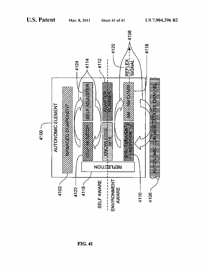
In other embodiments, an autonomic environmental safety45 device may include a self-monitor that is operable to receive
information from sensors and operable to monitor and ana-lyze the sensor information and access a knowledge reposi-tory; a self adjuster operably coupled to the self-monitor in aself control loop, the self adjuster operable to access the
5o knowledge repository, the self adjuster operable to transmitdata to effectors, and the self adjuster operable to plan andexecute; an environment monitor that is operable to receiveinformation from sensors and operable to monitor and ana-lyze the sensor information and access the knowledge reposi-
55 tory; an autonomic manager communications componentoperably coupled to the environment monitor in an environ-ment control loop, the autonomic manager communicationscomponent operable to access the knowledge repository, the
60 autonomic manager communications operable to produceand transmit a pulse monitor signal, the pulse monitor signalincluding a heart beat monitor signal and a reflex signal, thereflex signal including self health/urgency data and environ-ment health/urgency data.
65 Systems, clients, servers, methods, and computer-readablemedia of varying scope are described herein. In addition to theaspects and advantages described in this summary, further

US 7,904,396 B23
aspects and advantages will become apparent by reference tothe drawings and by reading the detailed description thatfollows.
BRIEF DESCRIPTION OF THE DRAWINGS
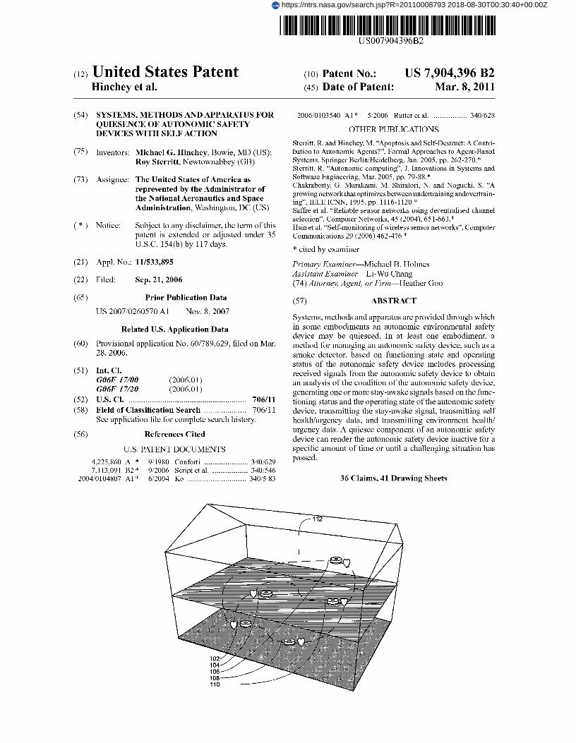
FIG. 1 is a block diagram of an overview of a system ofautonomic environmental safety devices, according to anembodiment;
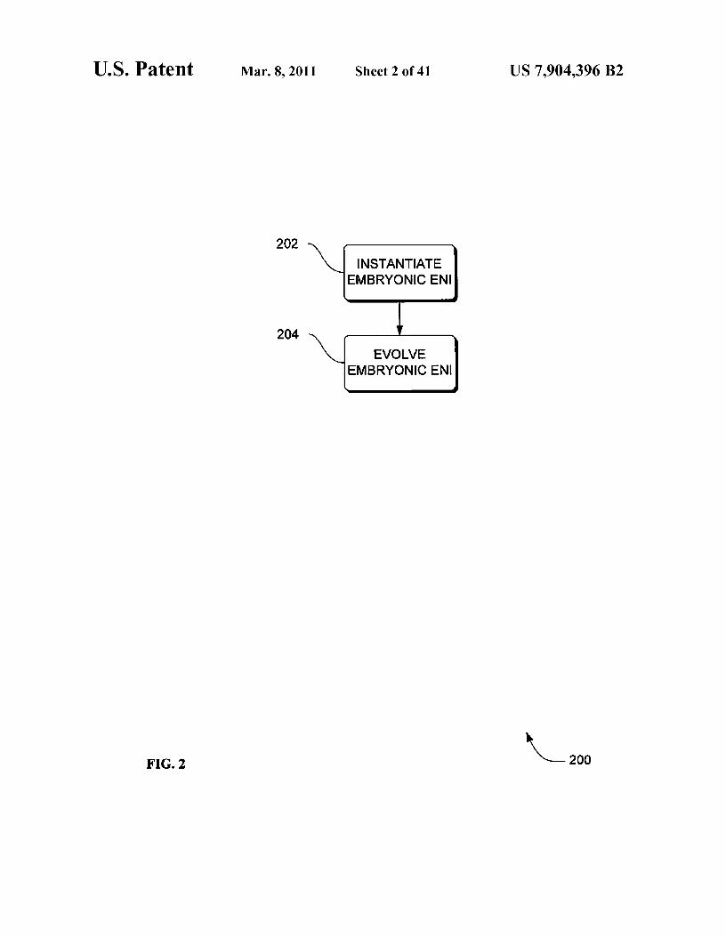
FIG. 2 is a flowchart of a method to construct an environ-ment to satisfy increasingly demanding external require-ments, according to an embodiment;
FIG. 3 is a flowchart of a method to construct an environ-ment to satisfy increasingly demanding external require-ments, according to an embodiment, where a ruler entitydecides to withdraw or generate a stay alive signal;
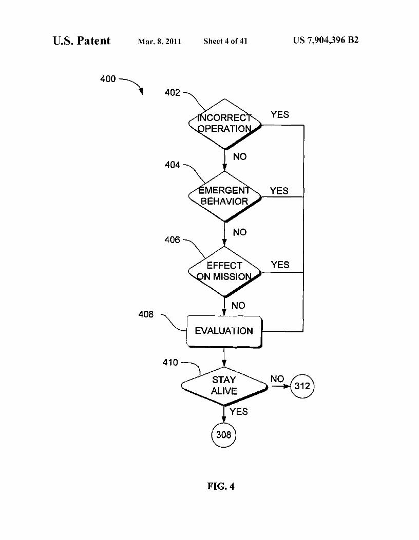
FIG. 4 is a flowchart for generating a stay alive signal whena warning condition occurs, according to an embodiment;
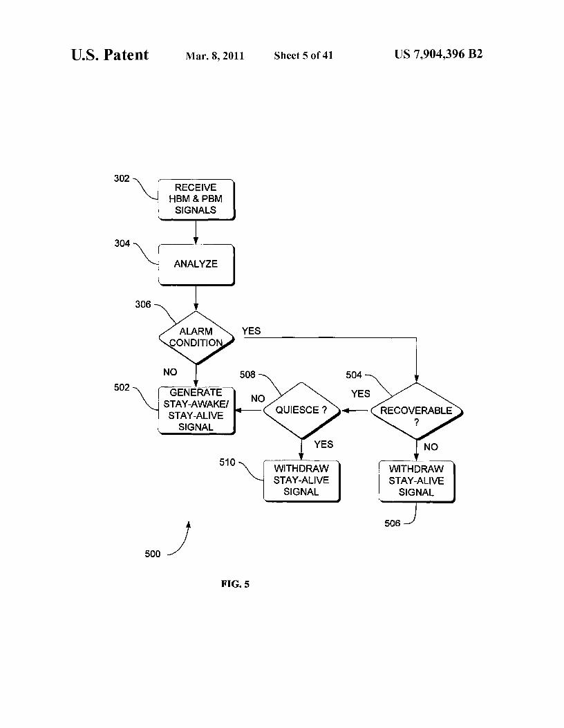
FIG. 5 is a flowchart of a method to construct an environ-ment to satisfy increasingly demanding external require-ments, according to an embodiment, where a ruler entitydecides to withdraw or generate a stay awake signal;
FIG. 6 is a flowchart for generating a stay awake signalwhen a warning condition occurs, according to an embodi-ment;
FIG. 7 is a flowchart for interrogating an anonymous auto-nomic agent, according to an embodiment;
FIG. 8 is a flowchart of a method of autonomic communi-cation by an autonomic element, according to an embodi-ment;
FIG. 9 is a flowchart of a method of autonomic communi-cation by an autonomic element, according to an embodi-ment;
FIG. 10 is a flowchart of a method of autonomic commu-nication by an autonomic element, according to an embodi-ment;
FIG. 11 is a flowchart of a method of autonomic commu-nication by an autonomic element, according to an embodi-ment.
FIG. 12 is a flowchart of a method in which a ruler entitycontrols a stay alive signal in an autonomic environmentalsafety device, according to an embodiment;
FIG. 13 is a flowchart of a method to determine the recov-erability of an alarm or other fault condition in an autonomicenvironmental safety device, according to an embodiment;
FIG. 14 is a flowchart of a method of a ruling autonomicdevice controlling a stay-awake signal of an autonomic envi-ronmental safety device, according to an embodiment;
FIG. 15 is a flowchart of a method for determining therecoverability of an alarm condition of an autonomic envi-ronmental safety device, according to an embodiment;
FIG. 16 is a flowchart of a method of a ruling autonomicdevice controlling a stay-awake signal of an autonomic envi-ronmental safety device, according to an embodiment;
FIG. 17 is a flowchart of a method of autonomic commu-nication by an autonomic environmental safety device,according to an embodiment;
FIG. 18 is a flowchart of a method of autonomic commu-nication by an autonomic environmental safety device,according to an embodiment;
FIG. 19 is a flowchart of a method of autonomic commu-nication by an autonomic environmental safety device,according to an embodiment;
FIG. 20 is a flowchart of a method of autonomic commu-nication by an autonomic environmental safety device,according to an embodiment;
4FIG. 21 is a block diagram of a conventional computer
cluster environment in which different embodiments can bepracticed;
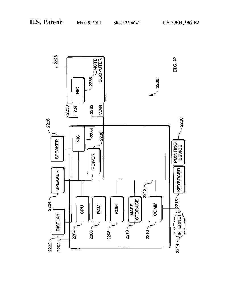
FIG. 22 is a block diagram of a conventional hardware and5 operating environment in which different embodiments can
be practiced;FIG. 23 is a block diagram of a conventional multiproces-
sor hardware and operating environment in which differentembodiments can be practiced;
10 FIG. 24 is a block diagram of a hardware and operatingenvironment which may include a quiesce component,according to an embodiment;
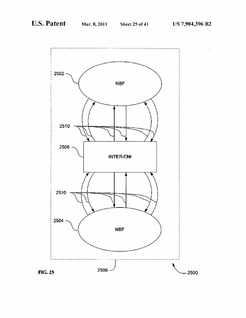
FIG. 25 is a block diagram of an apparatus of an evolvablesynthetic neural system to manage collective interactions
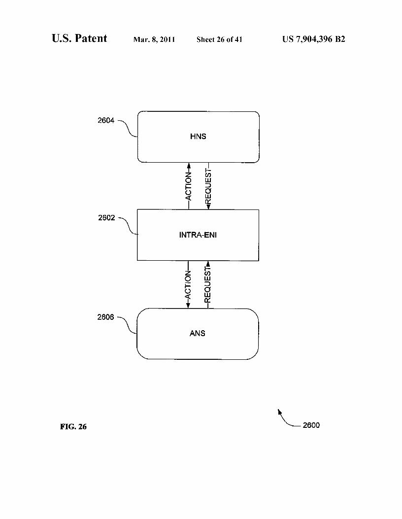
15 between autonomous entities, according to an embodiment;FIG. 26 is a block diagram of a neural basis function of a
worker, according to an embodiment;FIG. 27 is a block diagram of a heuristic neural system,
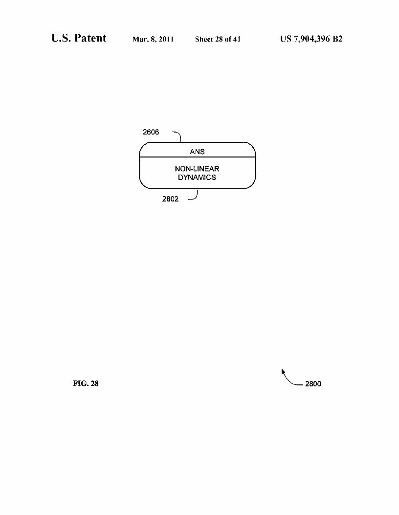
according to an embodiment;20 FIG. 28 is a block diagram of an autonomous neural sys-
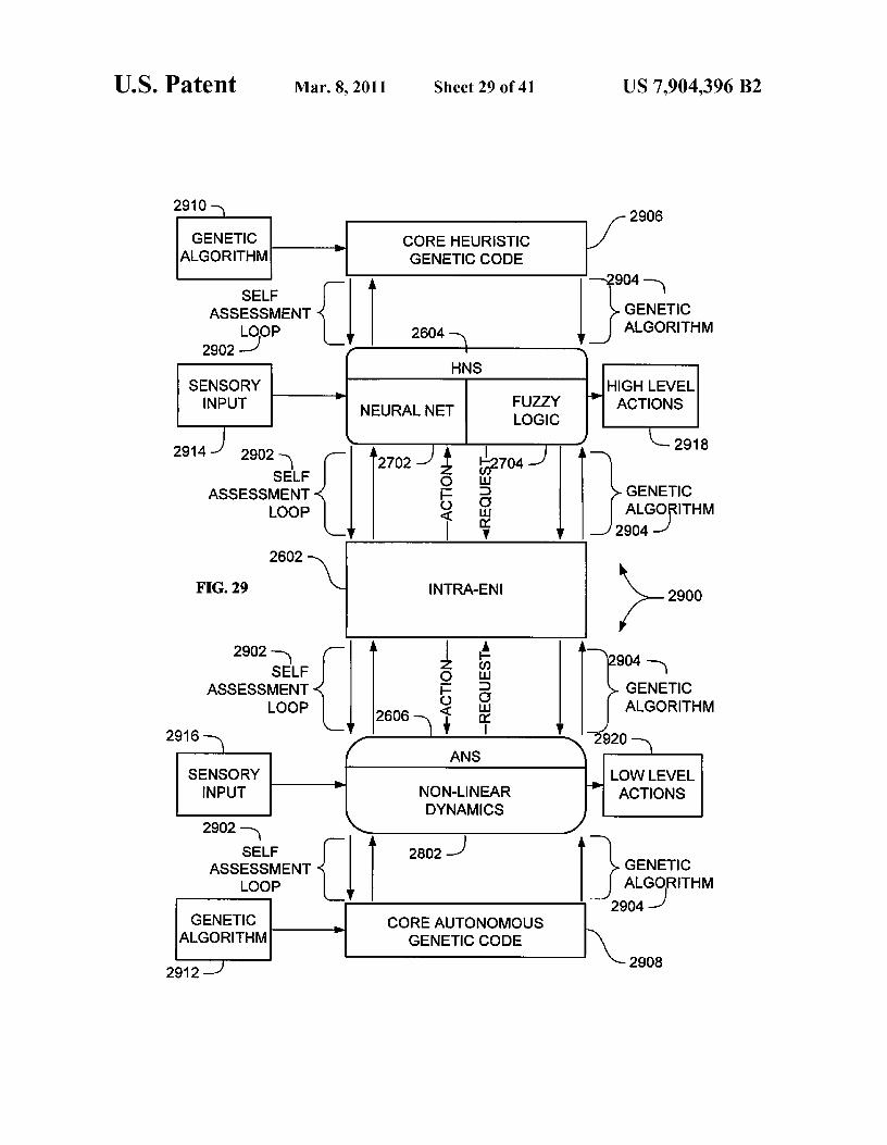
tem, according to an embodiment;FIG. 29 is a block diagram of a neural basis function of a
worker, according to an embodiment;FIG. 30 is a block diagram of a multiple level hierarchical
25 evolvable synthetic neural system, according to an embodi-ment;
FIG. 31 is a block diagram of a plurality of autonomicentities including autonomic environmental safety devicesassembled to perform a task, according to an embodiment;
30 FIG. 32 is a block diagram of an autonomous entity man-agement system, according to an embodiment;
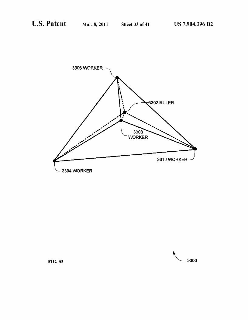
FIG. 33 is a diagram of a three dimensional hierarchicalevolvable synthetic neural system, according to an embodi-ment;
35 FIG. 34 is a diagram of a heuristic neural system, accordingto an embodiment, for a single instrument spacecraft to pros-pect asteroid belts;
FIG. 35 is a diagram of an autonomous entity managing asystem, according to an embodiment;
40 FIG. 36 is a diagram of autonomous entities interaction,according to an embodiment;
FIG. 37 is a block diagram of an autonomous entity man-agement system, according to an embodiment;
FIG. 38 is a hierarchical chart of an autonomous entity45 management system, according to an embodiment;
FIG. 39 is a block diagram of an autonomic element,according to an embodiment;
FIG. 40 is a block diagram of autonomy and autonomicityat a high system level, according to an embodiment; and
50 FIG. 41 is a block diagram of an architecture of an auto-nomic element (AE), according to an embodiment that mayinclude reflection and reflex layers.
DETAILED DESCRIPTION OF THE INVENTION55
In the following detailed description, reference is made tothe accompanying drawings that form a part hereof, and inwhich is shown by way of illustration specific embodimentsthat may be practiced. These embodiments are described in
60 sufficient detail to enable those skilled in the art to practice theembodiments, and it is to be understood that other embodi-ments may be utilized and that logical, mechanical, electricaland other changes may be made without departing from thescope of the embodiments. The following detailed descrip-
65 tion is, therefore, not to be taken in a limiting sense.The detailed description is divided into five sections. In the
first section, a system level overview is described. In the

US 7,904,396 B25
6second section, embodiments of methods are described. In
be operable to trip an alarm on the autonomic smoke detector
the third section, hardware and the operating environments in that detected an environmental condition.conjunction with which embodiments may be practiced are
In some embodiments, the autonomic smoke detectors
described. In the fourth section, particular implementations 102, 104, 106, 108 and 110 may also be operable to transmit
of apparatus are described. Finally, in the fifth section, a s a signal indicating failure of the autonomic smoke detectorsconclusion of the detailed description is provided. 102, 104, 106, 108 and 110. In other embodiments, all of the
autonomic smoke detectors 102, 104, 106, 108 and 110 maySystem Level Overview be operable to signal the failure of one of the other autonomic
smoke detectors 102, 104, 106, 108 and 110.FIG.1 is a block diagram of an overview of a system 100 of 10 In a situation where all but one of the autonomic smoke
autonomic environmental safety devices, according to an detectors 102, 104, 106, 108 and 110 in a building may beembodiment. System 100 may solve the need in the art to operating correctly (i.e., if one autonomic smoke detector isdiscover and report fault(s) or failure of the smoke detectors faulty, or to lose power, such as battery failure, etc.) the faultand may solve the need in the art to reduce the possibility that of that one autonomic smoke detector would be detected bysmoke detectors will jeopardize the mission of the system of 15 the failure of other autonomic smoke detectors 102, 104, 106,which the smoke detector is a part. 108 and 110 to receive a first "heartbeat' (the "lub") within a
The autonomic smoke detectors 102, 104, 106, 108 and specified period of time, and the second beat (the "dub") to110 (or other autonomic environmental safety devices), can carry operational data. The heartbeat (the "lub") can also betransmit status data such as environment health/urgency data known as a heart beat monitor (HBM) signal and second beatof the autonomic smoke detectors over a network 112. The 20 can also be known as a pulse monitor (PBM) signal. In somestatus data may be available for analysis by all of the auto- embodiments, if an alarm signal is to be sounded by one of thenomic smoke detectors 102, 104, 106, 108 and 110 and by autonomic smoke detectors, the second beat (the PBM) mayother entities that access the network 112. The status infor- convey the alarm information to the other autonomic smokemation can be analyzed to identify existing or potential faults detectors in the building so that the other autonomic smokeof the smoke detectors. Thus, system 100 may provide a 25 detectors can activate their own alarm.mechanism to determine if any of the autonomic environmen- In some embodiments, the autonomic smoke detectorstal safety devices may be faulty. 102, 104, 106, 108 and 110 may be operable to link devices
The autonomic smoke detectors 102, 104, 106, 108 and within a building together through wireless connections.110 and the network 112 may be organized in a heuristic System 100 may have applications and embodiments in aneural system (FINS) architecture. Each smoke detector can 30 large number of areas beyond a smoke detector. Beyondbe a member of a swarm of autonomous environmental safety smoke detectors, other types of autonomic environmentaldevices and may provide coordination and interaction safety devices may include burglar alarm systems, sprinklerbetween each FINS that yields performance of the aggregate systems, satellites, and any "sensor network" or monitoringof the swarm that exceeds the performance of a group of system where a number of simple sensors may be usedgeneralist autonomic environmental safety devices. ss together in a way that collects information regarding the
In some embodiments of system 100, each of a number of status of various devices. In some of these applications, theAESDs may be an autonomic smoke detector. Each auto- first beat of the lub-dub is used to carry health informationnomic smoke detector in a swarm may have a specialized
(i.e., that the device is functioning correctly and forwarding
mission, much like ants in an ant colony have a specialized
data readings in a timely fashion) and the second to carrymission. Yet, a heuristic neural system (FINS) architecture of 40 instructions or signals, either trigged by a particular eventeach autonomic smoke detector may provide coordination (e.g., detection of smoke) or to perform various operationaland interaction between each FINS that yields performance of
functions.
the aggregate of the AESDs that exceeds the performance of
The autonomic smoke detectors 102, 104, 106, 108 anda group of generalist AESDs. 110 may be a particular embodiment of autonomic environ-
A synthetic neural system may be defined as an informa- 45 mental safety devices that illustrate the principles of howtion processing paradigm that is inspired by biological ner- autonomic environmental safety devices in general operate.vous systems that process information, such as the brain. System 100 may provide a way for all smoke detectors in theBiological systems inspire system design inmany otherways, house/building to indicate environmental hazards. Wirelesssuch as reflex reaction and health signs, nature inspired sys- embodiments of the network 112 can provide for easy instal-tems, hive and swarm behavior, and fire flies, for example. so lation of the autonomic smoke detectors 102, 104, 106, 108These synthetic systems can provide an autonomic comput- and 110.ing entity that can be arranged to manage complexity, con- System 100 is not limited by the number of autonomictinuous self adjustment, adjustment to unpredictable condi- environmental safety devices. Some embodiments of systemtions, and prevention and recovery from failures. 100 may include one autonomic environmental safety device,
In some embodiments, a key element of synthetic neural ss some embodiments may include a plurality of autonomicsystems may be the general architecture of the synthetic neu- environmental safety devices.ral system. A synthetic neural system may be composed of alarge number of highly interconnected processing autonomic
Method Embodiments
elements that may be analogous to neurons in a brain workingin parallel to solve specific problems. Unlike general purpose 60 In the previous section, an overview of some systembrains, a synthetic neural system may be typically configured embodiments is described. In this section, embodiments offor a specific application and sometimes for a limited dura- particular methods of such embodiments are described bytion. reference to a series of flowcharts. Describing the methods by
In some embodiments of system 100, the autonomic smoke reference to a flowchart enables one skilled in the art todetectors 102, 104, 106, 108 and 110 may be operable to 65 develop such programs, firmware, or hardware, includingsignal a network alarm, and in some embodiments, the auto- such instructions to carry out the methods on suitable com-nomic smoke detectors 102, 104, 106, 108 and 110 may also puters, executing the instructions from computer-readable

US 7,904,396 B27
8media. Similarly, the methods performed by the server com- neering data summarization can be a set of abstractionsputer programs, firmware, or hardware may also be com- regarding sensor that may comprise rise and fall of data by aposed of computer-executable instructions. In some embodi- certain amount, external causes for parameter deviations,ments, method 200 may be performed by a program actual numerical value of the parameters being summarized,executing on, or performed by firmware or hardware that is a 5 warning conditions, alarm conditions, and any other summa-part of a computer, such as computer 2202 in FIG. 22. rization that would convey the general health of the system.
FIG. 2 is a flowchart of a method 200 to construct an
Once the HBM and PBM signals have been received, controlenvironment to satisfy increasingly demanding external
can be forwarded to action 304 for further processing.
requirements, according to an embodiment. In action 304, an analysis ofthe HBM and PBM signal mayMethod 200 may include instantiating 202 an embryonic io be performed to determine trends and possible areas of con-
evolvable neural interface (ENI). In some embodiments, the cern. Some purposes of the analysis may be to determineembryonic ENI lacks a complete specification of the opera- exceedance from a predetermined condition, make projectiontional characteristics of the ESNS or an ENI. The embryonic through simulation and data modeling areas of parametersENI can be a neural thread possessing only the most primitive that can lead to the failure of the worker entity or that mightand minimal connectivity. 15 jeopardize the assigned mission, and ascertain the quality of
Method 200 can further include evolving 204 the embry- performance of the system. The analysis can be performed byonic ENI towards complex complete connectivity. Specifica- using regression techniques, neural network techniques, sta-tions of the inter-ENI 106 can be developed from the initial
tistical techniques, or any other technique that can convey
embryonic form. Thus, a very complex problem that, in some
information about the state of a system or emergent behaviorembodiments, may be represented by a complete specifica- 20 of the system. Once the analysis has been performed, controltion can be replaced by a simpler specification of the embry- can pass to action 306 for further processing.onic ENI that is evolved to meet increasingly demanding
In action 306, an alarmed condition may be determined. In
requirements. Progression from an embryonic state to a more action 306, the analysis of action 304 may be consulted tocomplex state can avoid the necessity of specifying the com- determine if there is one or more alarm condition that canplex complete connectivity initially, but rather can reduce the 25 trigger the withdrawal of a stay alive signal. If it is determinedproblem to one of developing methods to drive the evolution that there are no alarm conditions, control may be passed toof simple limited connectivity to complex complete connec- action 308 so as to generate a stay alive signal. In the eventtivity. that an alarm condition is present, control may be passed to
An adaptive or evolutionary nature of an artificial intelli- action 310 for further processing.gence construct in method 200 can be predicated on an active 30 In action 310, a determination may be made to ascertainrevision of the embryonic ENI to meet external action whether the identified alarmed condition of action 306 isrequirements for a sensory input. In particular, the ENI can recoverable by the managed entity. When an alarmed condi-evolve due to changing conditions that are either driven by tion is determined to be recoverable, control maybe pas sed totraining requirements or operational requirements. action 308 to generate a stay alive signal. When an alarmed
In some embodiments, method 200 may be implemented as 35 condition is determined not to be recoverable, control may bea computer data signal embodied in a carrier wave that rep- passed to action 312 to withdraw the stay alive signal. Methodresents a sequence of instructions, which, when executed by
400 below can be one embodiment of determining 310 if thea processor, such as processor 2204 in FIG. 22, causes the
identified alarmed condition is recoverable.
processor to perform the respective method. In other embodi- FIG. 4 is a flowchart of a method 400 for ascertaining thements, method 200 may be implemented as a computer-ac- 4o recoverability of an alarmed condition determined at actioncessible medium having executable instructions capable of
306, according to an embodiment. Method 400 may solve the
directing a processor, such as processor 2204 in FIG. 22, to need in the art for management of autonomous entities thatperform the respective method. In varying embodiments, the can be functionally extracted from an environment upon themedium can be a magnetic medium, an electronic medium, or occurrence of a predetermined condition. Method 400 may bean optical medium. 45 one possible embodiment of the action in FIG. 3 above of
FIG. 3 is a flowchart of a method 300 to construct an
determining 310 if the identified alarmed condition is recov-environment to satisfy increasingly demanding external
erable.
requirements, according to an embodiment, where a ruler
Method 400 may begin with action 402 when receiving oneentity decides to withdraw or generate a stay alive signal. or more alarmed condition. In action 402, there may be aMethod 300 may solve the need in the art for management of 5o determination if an incorrect operation from the managedautonomous entities that can be functionally extracted from system has been identified in action 304 of FIG. 3. An incor-an environment upon the occurrence of a predetermined con- rect operation can range from not initializing sensors to fail-dition. Method 300 can begin with action 3 02 when receiving
ing to self-heal when internal decision logic recommends
a signal from a managed entity. such as an appropriate cause of action. In action 402, inAction 302 can receive a heart beat monitor (HBM) signal 55 addition to determining if an incorrect operation has been
and pulse monitor (PBM) signal from a managed entity such
identified, it may also be possible to ascertain the number ofas worker entities 3118 or 3120. The HBM signal can be an
devices or processes within the entity that registered an incor-
indication that the managed entity (worker entity) is operat- rect operation. If at least one incorrect operation is deter-ing. The HBM can be an "ON/OFF" state signal, an indication mined, the action may transfer the identity of the unit tothat a process is being performed, or any other signal that can 60 evaluation block 408 for further processing.convey information that the worker entity is alive or active. In action 404, there may be a determination whether emer-The PBM signal may extend the HBM signal to incorporate gent behavior from the managed system has been identified inreflex/urgency/health indicators from the autonomic manager action 304 of FIG. 3. An emergent behavior or emergentrepresenting its view of the current self-management state. property can appear when a number of entities (agents) oper-The PBM signal can thus convey the performance and char- 65 ate in an environment forming behaviors that are more com-acteristics of the entity in the form of engineering data sum- plex as a collective. The property itself can often be unpre-marization to add context to the received HBM signal. Engi- dictable and unprecedented and can represent a new level of
US 7,904,396 B29
the system's evolution. This complex behavior in the contextof control system may be known as non-linearity, chaos, orcapacity limits. The complex behavior or properties may notbe properties of any single such entity, nor can they easily bepredicted or deduced from behavior in the lower-level enti-ties. One reason why emergent behavior occurs may be thatthe number of interactions between autonomic componentsof a system increases combinatorially with the number ofautonomic components, thus potentially allowing for manynew and subtle types of behavior to emerge. Nothing maydirectly command the system to form a pattern, but the inter-actions of each part (entities) to its immediate surroundingsmay cause a complex process that leads to order. Emergentbehavior can be identified based on parameters that give riseto the complex behavior in a system such as demands onresources. Once an emergent behavior condition has beenidentified, the information may be forwarded to evaluationblock 408 for further processing.
In action 406, a determination may be made of alarmconditions that can have an impact on the success of themission or task by which all entities are striving to accom-plish. The impact could be the ability to accomplish indi-vidual tasks or the potential for failure of the overall missionby permitting an entity to stay alive. This impact can bedetermined through Bayesian belief networks, statisticalinference engines, or by any other presently developed orfuture developed inference engine that can ascertain theimpact on a particular task if one or more agent is showingincorrect operation or harmful emergent behavior. Once theimpact has been determined the information may be pas sed toevaluation block 408 for further processing.
Evaluation block 408 may marshal the incorrect operationidentified in action 402, the emergent behavior in action 404,or the effect on mission in action 406 to suggest a course ofaction that the managed entities should adopt, which in theillustrated embodiment is based on a stay alive signal. Thedetermination of withdrawing or affirming the stay alive sig-nal can be based on the occurrence of one or more of theidentified alarmed conditions, or a combination of two ormore of the identified alarmed conditions. For example, thestay alive signal could be withdrawn if there is emergentbehavior and there would be an effect on the mission. In thealternative, the stay alive signal could be affirmed if there wasonly emergent behavior, or incorrect operation. Once theevaluation is determined, control may be passed to decisionblock 410 for further processing in accordance to the decisionmade in evaluation block 408.
In action 410, if the desired control instruction is to main-tain the stay alive signal, control can be passed to action 308for further processing. In the alternative, a withdrawal of thestay alive signal can be sent to action 312 for further process-ing. It should be noted that generating a stay alive signal maybe equivalent to generating a stay alive signal, affirming a stayalive signal, not withdrawing a stay alive signal, or any othercondition that can determine if an entity is to perish or toextinguish unless allowed to continue by another entity. Theother entity might be a managing entity since it can determinethe outcome (life or death) of an entity.
FIG. 5 is a flowchart of a method 500 to construct anenvironment to satisfy increasingly demanding externalrequirements according to an embodiment where a rulerentity decides to withdraw or generate a stay-awake signal.Method 500 may solve the need in the art to reduce thepossibility that an autonomic element will jeopardize themission of the autonomic element.
Method 500 may begin with action 302 when receiving asignal from a managed entity. Action 302 can receive a heart
10beat monitor (HBM) signal and pulse monitor (PBM) signalfrom a managed entity such as worker entities 1418 or 1420.In some embodiments, the HBM signal is an indication thatthe managed entity (worker entity) is operating. The HBM
5 can be an "ON/OFF" state signal, an indication that a processis being performed, or any other signal that can convey infor-mation that the worker entity is awake or active. The PBMsignal may extend the HBM signal to incorporate reflex/urgency/health indicators from the autonomic manager rep-
ro resenting its view of the current self-management state. ThePBM signal may thus convey the performance and character-istics of the entity in the form of engineering data summari-zation to add context to the received HBM signal. Engineer-ing data summarization could be a set of abstractions
15 regarding sensors that, in some embodiments, could compriserise and fall of data by a certain amount, external causes forparameter deviations, actual numerical value of the param-eters being summarized, warning conditions, alarm condi-tions, and any other summarization that would convey the
20 general health of the system. Oncethe HBMandPBM signalshave been received, control can be forwarded to action 304 forfurther processing.
In action 304, an analysis ofthe HBM and PBM signal may25 be performed to determine trends and possible areas of con-
cern. The purpose of the analysis could be to determine that apredetermined condition has been exceeded, generate a pro-jection through simulation and data modeling areas of param-eters that can lead to the failure of the worker entity or that
so mightjeopardizethe assigned mission, andascertainthe qual-ity of performance of the system. The analysis can be per-formed by using regression techniques, neural network tech-niques, statistical techniques, or any other technique that canconvey information about the state of a system or emergent
35 behavior of the system. Once the analysis has been per-formed, control can be passed to action 306 for further pro-cessing.
In action 306, an alarmed condition can be determined. Inaction 306, the analysis of action 304 may be consulted to
40 determine if there is one or more alarm condition that cantrigger the withdrawal of a stay-awake signal. If it is deter-mined that there are no alarm conditions, control may bepassed to action 502 so as to generate a stay-alive signal. Inthe event that an alarm condition is present, control may be
45 passed to action 504 for further processing.In action 504, a determination can be made to ascertain if
the identified alarmed condition of action 306 is recoverableby the managed entity such as worker entities 1418 and 1420of FIG. 14. When an alarmed condition is determined not to
5o be recoverable, control may be passed to action 312 to with-draw the stay-alive signal. Method 600 below could be oneembodiment of determining 504 if the identified alarmedcondition is recoverable. When an alarmed condition is deter-mined to be recoverable, control may be passed to action 508
55 in which a determination canbe made to ascertain if quiescingthe managed entity and/or subsequent recovery is possible.When quiescence of the managed entity and/or need for laterrecovery is determined as not possible, control can pass toaction 502 to generate a stay-awake/stay-alive-signal. When
6o quiescence of the managed entity is determined as possibleand/or needed in action 508, control can pass to action 510, towithdraw the stay-awake signal. Thus, quiescing the man-aged entity may solve the need in the art to functionallyextract the managed entity from an environment upon the
65 occurrence of an alarmed condition. Quiescence maybe a lessencompassing alternative to withdrawing the stay-awake sig-nal of apoptosis. Method 500 can allow an agent or craft that

US 7,904,396 B211
is in danger or endangering the mission to be put into aself-sleep mode, then later reactivated or self-destructed.
FIG. 6 is a flowchart of a method 600 for ascertaining therecoverability of an alarmed condition determined at action504. Method 600 may solve the need in the art for manage- 5
ment of autonomous entities that can be functionallyextracted from an environment upon the occurrence of apredetermined condition. Method 600 may begin with action402 when receiving one or more alarmed condition.
In action 402, there may be a determination if an incorrect iooperation from the managed system has been identified inaction 304 of FIG. 3. An incorrect operation can range fromnot initializing sensors to failing to self-heal when internaldecision logic recommends such as an appropriate cause ofaction. In action 402, in addition to determining if an incorrect 15
operation has been identified, it may also be possible to ascer-tain the number of devices or processes within the entity thatregistered an incorrect operation. If at least one incorrectoperation is determined, the action can transfer the identity ofthe unit to evaluation block 408 for further processing. 20
In action 404, there may be a determination of emergentbehavior from the managed system that has been identified inaction 304 of FIG. 3. An emergent behavior or emergentproperty can appear when a number of entities (agents) oper-ate in an environment forming behaviors that are more com- 25
plex as a collective. The property itself may often be unpre-dictable and unprecedented and can represent a new level ofthe system's evolution. This complex behavior in the contextof control system can be known as non-linearity, chaos, orcapacity limits. The complex behavior or properties may not 30
be properties of any single such entity, nor can they easily bepredicted or deduced from behavior in the lower-level enti-ties. One reason why emergent behavior occurs could be thatthe number of interactions between autonomic componentsof a system increases combinatorially with the number of 35
autonomic components, thus potentially allowing for manynew and subtle types of behavior to emerge. Nothing maydirectly command the system to form a pattern, but instead theinteractions of each part (entities) to its immediate surround-ings can cause a complex process that leads to order. Emer- 40
gent behavior can be identified based on parameters that giverise to the complex behavior in a system such as demands onresources. Once an emergent behavior condition has beenidentified, the information may be forwarded to evaluationblock 408 for further processing. 45
In action 406, a determination can be made of alarm con-ditions that can have an impact on the success of the missionor task which all entities are striving to accomplish. Theimpact could be the ability to accomplish individual tasks orthe potential for failure of the overall mission by permitting 50
an entity to stay awake. This impact can be determinedthrough Bayesian belief networks, statistical inferenceengines, or by any other presently developed or future devel-oped inference engine that can ascertain the impact on aparticular task if one or more agent is showing incorrect 55
operation or harmful emergent behavior. Once the impact hasbeen determined, the information may be passed to evaluationblock 408 for further processing.
Evaluation block 408 can marshal the incorrect operationidentified in action 402, the emergent behavior in action 404, 60
and the effect on mission in action 406 to suggest a course ofaction that the managed entities should adopt, which in theillustrated embodiment is based on a stay-awake signal. Thedetermination of withdrawing or affirming the stay-awakesignal can be based on the occurrence of one or more of the 65
identified alarmed conditions, or a combination of two ormore of the identified alarmed conditions. For example, the
12stay-awake signal could be withdrawn if there is emergentbehavior and there would be an effect on the mission. In thealternative, the stay-awake signal could be affirmed if therewas only emergent behavior, or incorrect operation. Once theevaluation is determined, control can pass to decision block602 for further processing in accordance with the decisionmade in evaluation block 408.
In action 602, if the desired control instruction is to main-tain the stay-awake signal, control can be passed to action 508for further processing. In the alternative, a withdrawal of thestay-awake signal can be sent to action 506 for further pro-cessing. It shouldbe noted that generating a stay-awake signalis equivalent to affirming a stay awake signal, not withdraw-ing a stay awake signal, or any other condition that can deter-mine if an entity is to perish or to extinguish unless allowed tocontinue by another entity. The other entity could be a man-aging entity since it can determine the outcome (life or death)of an entity.
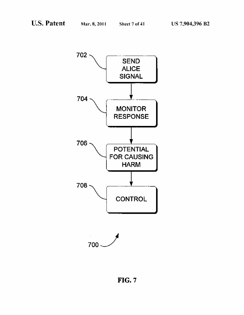
FIG. 7 is a flowchart of a method 700 for providing securityrequirements, according to an embodiment, where a rulerentity decides to withdraw or generate a stay alive signal froman anonymous agent. Method 700 may solve the need in theart for management of autonomous entities that can be func-tionally extracted from an environment upon the occurrenceof a predetermined condition. Method 700 may begin withaction 702 where an Alice signal is sent to an anonymousagent to ascertain the agent's potential forharm to a system asshown in FIG. 4. After the Alice signal has been sent to theagent, control may be passed to action 704 for further pro-cessing.
In action 704 the response from the agent may be moni-tored. Monitored as used herein refers to maintaining regularsurveillance, or close observation, over an anonymous agentand can include the absence of a signal. For example, notresponding with a timeout period is considered, as usedherein, as monitor response. After action 704 is completed,control may be passed to action 706 for further processing.
In action 706, the monitored response from action 704 maybe analyzed to determine if it is in an appropriate format,within a certain timeout period, and with a valid and justifiedreason for being within the locus of interest or domain of theautonomous system. Once the potential for causing harm hasbeen ascertained, control may be passed to action 708 forfurther processing.
In action 708, the system may control the future of theanonymous agent based on the potential for harm to theautonomous system. This mimics the mechanism of celldeath in the human (and animal) body, and hence makes useof autonomic and other biologically inspired metaphors. Thetechnique would send self-destruct signals to agents that canbe compromised, or which cannot be identified as friendly oras having a right to access certain resources. The concept oftheALice signal is to challenge a mobile agent to determine ifit is friendly and has permission to access certain resources. Ifit fails to identify itself appropriately following an Aliceinterrogation, it may be blocked from the system and giveneither a self-destruct signal, or its stay alive reprieve is with-drawn. As an alternative to the ALice signal, a quiesce signal,command or instruction can be sent. The quiesce signal isdiscussed in more detail in conjunction with FIGS. 5, 6 and10.
FIG. 8 is a flowchart of a method 800 of autonomic com-municationby an autonomic element. Method 800 can offer aholistic vision for the development and evolution of com-puter-based systems that brings new levels of automation anddependability to systems, while simultaneously hiding theircomplexity and reducing their total cost of ownership.

US 7,904,396 B213
Method 800 may include transmitting self health/urgencydata 802. Examples of the self health/urgency data mayinclude information describing low battery power and/orfailed sensors. Method 800 may also include transmitting 804environment health/urgency data. Examples of the environ- 5
ment health/urgency data may include information describ-ing inaccessible devices, unauthorized access, and/or an uni-dentified mobile agent sending communication signals.
Transmitting 802 and 804 can be performed in any order 10
relative to each other. For example, in one embodiment thetransmitting 802 self health/urgency data may be performedbefore transmitting 804 environment health/urgency data. Inanother embodiment, transmitting 804 environment health/urgency data may be performed before transmitting 802 self 15
health/urgency data. In yet another embodiment, the selfhealth/urgency data may be transmitted simultaneously withthe environment health/urgency data. For example, the envi-ronment health/urgency data and the self health/urgency datamay be transmitted together. One example of transmitting the 20
environment health/urgency data and the self health/urgencydata may include encapsulating the environment health/ur-gency data and the self health/urgency data in a X.25 packet,although one skilled in the art will readily recognize that anynumber of alternative packet types may be used that fall
25within the scope of this invention. The environment health/urgency data and the self health/urgency data can be thoughtof together as the "lub-dub" of a heartbeat in which the two"beats" or two pieces of data are transmitted simultaneously.The X.25 standard is published by the ITU Telecommunica- 30tion Standardization Sector at Place des Nations, CH-1211Geneva 20, Switzerland.
An autonomic environment may require that autonomicelements and, in particular, autonomic managers communi-cate with one another concerning self-* activities, in order to 35
ensure the robustness of the environment. A reflex signal4120 of FIG. 41 below can be facilitated through the pulsemonitor (PBM). A PBM can be an extension of the embeddedsystem's heart-beat monitor, or HBM, which safeguards vitalprocesses through the emission of a regular "I am alive" 40signal to another process with the capability to encode selfhealth/urgency data and environment health/urgency data as asingle pulse. HBM is described in greater detail in FIG. 35, 36below and FIG. 3 above. Together with the standard eventmessages on an autonomic communications channel, this 45
may provide dynamics within autonomic responses and mul-tiple loops of control, such as reflex reactions among theautonomic managers. Some embodiments of the autonomicmanager communications (AM/AM) component 4118 mayproduce a reflex signal 4120 that includes the self health/ 50urgency data and the environment health/urgency data inaddition to the HBM. More concisely, the reflex signal cancarry a PBM. A reflex signal that carries a PBM can be usedto safe-guard the autonomic element by communicatinghealth of the autonomic element to another autonomic unit. 55For instance, in the situation where each PC in a LAN isequipped with an autonomic manager, rather than each of theindividual PCs monitoring the same environment, a few PCs(likely the least busy machines) can take on this role and alertthe others through a change in pulse to indicate changing 60
circumstances.In some embodiments, an aspect of the reflex reaction and
the pulse monitor may be the minimization of data sentessentially only a "signal" may be transmitted. Strictly speak-ing, this may not be mandatory; more information canbe sent, 65
yet the additional information should not compromise thereflex reaction.
14Just as the beat of the heart has a double beat (lub-dub), the
autonomic element's pulse monitor can have a double beatencoded as described above, a self health/urgency measureand an environment health/urgency measure. These matchdirectly with the two control loops within the AE, and theself-awareness and environment awareness properties.
FIG. 9 is a flowchart of a method 900 of autonomic com-munication by an autonomic element. Method 900 mayinclude transmitting 902 event message data in addition to theself and environment health/urgency data. Event messagedata can include data describing a change in condition, or adeviation from a normal operation. Event message data isdescribed in more detail below in connection with FIG. 36.
In some embodiments, the self health/urgency data andenvironment health/urgency data encoded with the standardevent messages on an autonomic communications channelmay provide dynamics within autonomic responses and mul-tiple loops of control, such as reflex reactions among anautonomic manager.
FIG. 10 is a flowchart of a method 1000 of autonomiccommunication by an autonomic element. Method 1000 mayinclude receiving 1002 the self health/urgency data from aself control loop component of the autonomic element. Oneexample of the self control loop component of the autonomicelement may be the self awareness control loop 4114 of theautonomic element 4100 of FIG. 41 below.
Method 1000 may also include receiving 1004 the envi-ronment health/urgency data from an environment controlloop component of the autonomic element. One example ofthe environment control loop component of the autonomicelement may be the environment awareness control loop 4108of the autonomic element 4100 of FIG. 41 below.
FIG. 11 is a flowchart of a method 1100 of autonomiccommunication by an autonomic element. Method 1100 mayoffer a holistic vision for the development and evolution ofcomputer-based systems that brings new levels of automationand dependability to systems, while simultaneously hidingtheir complexity and reducing processing delays by systemsthat receive data from the autonomic element.
Method 1100 may include transmitting uncompressed selfhealth/urgency data 1102. Method 1100 may also includetransmitting 1104 uncompressed environment health/ur-gency data. In the absence of bandwidth concerns, the uncom-pressed data can be acted upon quickly and not incur process-ing delays. One important aspect may be that the data,whether uncompressed or sent in some other form, should bein a form that can be acted upon immediately and not involveprocessing delays (such as is the case of event correlation).Transmitting 1102 and 1104 can be performed in any orderrelative to each other.
FIG. 12 is a flowchart of a method 1200 in which a rulerentity controls a stay alive signal in an autonomic environ-mental safety device, according to an embodiment. Method1200 may solve the need in the art for management of autono-mous entities that can be functionally extracted from an envi-ronment upon the occurrence of a predetermined condition.
Method 1200 may include the ruler entity receiving 1202 aheart beat monitor (HBM) signal and pulse monitor (PBM)signal from the autonomic environmental safety device(AESD) or other managed entity. The HBM signal may be anindication that the autonomic environmental safety devicemay be operating. The HBM can be an "ON/OFF" statesignal, an indication that a process may be being performed,or any other signal that can convey information that the auto-nomic environmental safety device is alive or active. ThePBM signal may extend the HBM signal to incorporatereflex/urgency/health indicators from the autonomic manager

US 7,904,396 B215
16representing its view of the current self-management state. future developed inference engine that can ascertain theThe PBM signal thus can convey the performance and char- impact on a particular task if one or more AESDs is showingacteristics of the entity in the form of engineering data sum- incorrect operation or alarm conditions.marization to add context to the received HBM signal. Engi- Evaluation block 1306 may reference the battery levelneering data summarization may be a set of abstractions 5 determined in action 1302 and the operability of the AESDregarding sensors that may comprise rise and fall of data by a
determined in action 1304 to suggest a course of action that
certain amount, external causes for parameter deviations, the managed entities should adopt, which in method 1300 isactual numerical value of the parameters being summarized, illustrated as being based on a stay alive signal. The determi-warning conditions, fault conditions, and any other summa- nation of withdrawing or affirming the stay alive signal can berization that would convey the general health of the system. io based on the occurrence of one or more of the identified faultAfter the HBM and PBM signals have been received, control
conditions, or a combination of two or more of the identified
may be forwarded to action 1204 for further processing. fault conditions. For example, the stay alive signal could beIn action 1204, an analysis of the HBM and PBM signal
withdrawn if there is emergent behavior and there would be
may be performed to determine trends and possible areas of
an effect on the mission. In the alternative, the stay aliveconcern. The purpose of the analysis may be to determine that 15 signal could be affirmed if there was only emergent behavior,• predetermined condition may have been exceeded, generate or incorrect operation. After the evaluation is determined,• projection through simulation and data modeling areas of
control can pass to decision block 1308 for further processing
parameters that can lead to the failure of the autonomic envi- in accordance to the decision made in evaluation block 1306.ronmental safety device or that might jeopardize the assigned
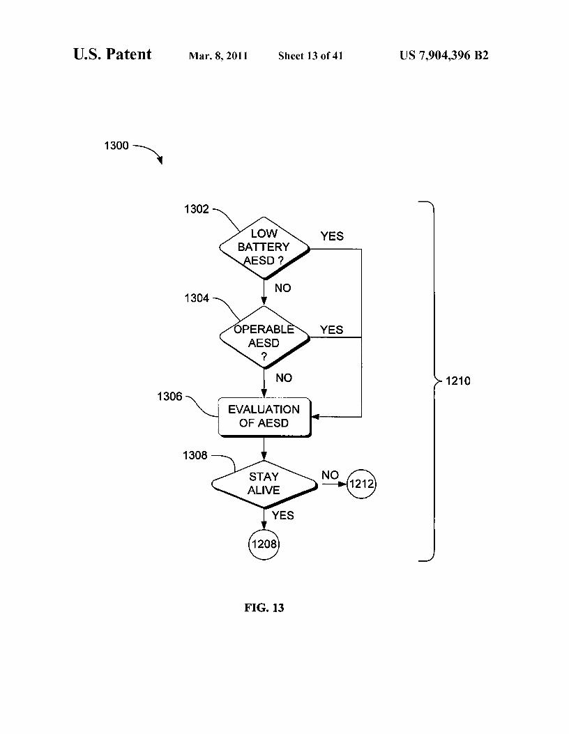
In action 1308, if the desired control instruction is to main-
mission, and ascertain the quality of performance of the sys- 20 tain the stay alive signal, control can be passed to action 1208tem. The analysis can be performed by using regression tech- for further processing. In the alternative, a withdrawal of theniques, neural network techniques, statistical techniques, or stay alive signal may be sent to action 1212 for further pro-any other technique that can convey information about the cessing. It should be noted that generating a stay alive signalstate of a system or emergent behavior of the system. can be equivalent to generating a stay alive signal, affirming a
In action 1206, the existence of an alarm condition may be 25 stay alive signal, not withdrawing a stay alive signal, or anydetermined. In action 1206, the analysis of action 1204 can be other condition that can determine if an entity is to perish orreferenced to determine existence of one or more alarms or to extinguish unless allowed to continue by another entity.other fault conditions that can trigger the withdrawal of a stay
The other entity may be a managing entity since it can deter-
alive signal. If no fault conditions may be determined to exist, mine the outcome (life or death) of an entity.control may be passed to action 1208 so as to generate a stay so FIG. 14 is a flowchart of a method 1400 of a ruling auto-alive signal. nomic device controlling a stay-awake signal, according to an
Inaction 1210, a determination maybe made to ascertain if
embodiment. Method 1400 may solve the need in the art tothe identified alarm or fault condition of action 1206 is recov- reduce the possibility that an autonomic environmental safetyerable by the autonomic environmental safety device. When
device will j eopardize the facility or mi ssion of the autonomic
an alarm or fault condition is determined to be recoverable, 35 environmental safety device.control may be passed to action 1208 to generate a stay alive
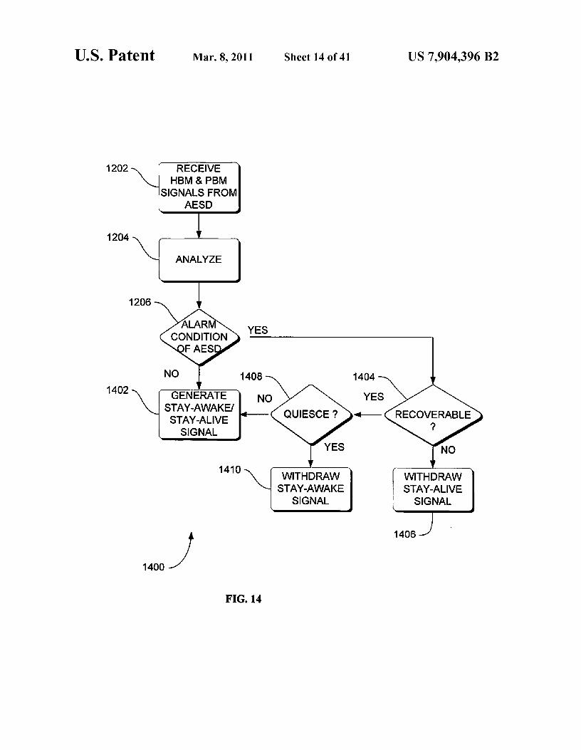
Method 1400 may include receiving 1202 a signal from an
signal. When an alarm or fault condition is determined not to autonomic environmental safety device (AESD) or somebe recoverable, control may be passed to action 1212 to other managed entity. Action 1202 may receive a heart beatwithdraw the stay alive signal. Method 1300 below is one monitor (HBM) signal and pulse monitor (PBM) signal fromembodiment of determining 1210 if the identified fault con- 40 the autonomic environmental safety device. The HBM signaldition is recoverable. may be an indication that the autonomic environmental safety
FIG. 13 is a flowchart of a method 1300 to determine the
device is operating. The HBM signal can be an "ON/OFF"recoverability of an alarm or other fault condition in an auto- state signal, an indication that a process is being performed, ornomic environmental safety device, according to an embodi- any other signal that can convey information that the auto-ment. Method 1300 may solve the need in the art for man- 45 nomic environmental safety device is awake or active. Theagement of autonomic environmental safety devices that can
PBM signal may extend the HBM signal to incorporate
be functionally extracted from an environment upon the reflex/urgency/health indicators from the autonomic manageroccurrence of a predetermined condition. Method 1300 is one representing its view of the current self-management state.embodiment of the action in FIG. 12 above of determining
The PBM signal thus can convey the performance and char-
1210 if the identified fault condition is recoverable. 5o acteristics of the entity in the form of engineering data sum-Method 1300 may begin with determining 1302 if a battery marization to add context to the received HBM signal. Engi-
of the autonomic environmental safety device (AESD) is neering data summarization can be a set of abstractionsemitting low amounts ofpower. If the battery is determined to regarding sensors that may comprise rise and fall of data by abe emitting low power, control can pass to evaluation block
certain amount, external causes for parameter deviations,
1306 for further processing. 55 actual numerical value of the parameters being summarized,If the battery is determined to be not emitting low power, warning conditions, fault conditions, and any other summa-
control canpass to determining 1304 if the AESD is operable. rization that would convey the general health of the system.After determining if theAESD is operable, control can pass to
After the HBM and PBM signals have been received, control
evaluation block 1306 for further processing. can be forwarded to action 1204 for further processing.In action 1306, a determination may be made of fault 60 In action 1204, an analysis of the HBM and PBM signal
conditions that can have an impact on the success of the may be performed to determine trends and possible areas ofmi ssion or taskby which all entities maybe striving to accom- concern. The purpose of the analysis may be to determine thatplish. The impact could be the ability to accomplish indi- • predetermined condition may have been exceeded, generatevidual tasks or the potential for failure of the overall mission • projection through simulation and data modeling areas ofby permitting an entity to stay alive. The impact can be 65 parameters that can lead to the failure of the autonomic envi-determined through Bayesian belief networks, statistical
ronmental safety device or that might jeopardize the assigned
inference engines, or by any other presently developed or mission, and ascertain the quality of performance of the sys-

US 7,904,396 B217
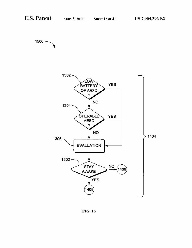
18tem. The analysis can be performed by using regression tech- Evaluation block 1306 may reference the battery levelniques, neural network techniques, statistical techniques, or
determined in action 1302 and the operability of the AESD
any other technique that can convey information about the
determined in action 1304 to suggest a course of action thatstate of a system or emergent behavior of the system. After the theAESDs should adopt, which in method 1500 is illustratedanalysis has been performed, control can pass to action 1206 5 as being based on a stay awake signal. The determination offor further processing. withdrawing or affirming the stay awake signal can be based
In action 1206, existence or non-existence of an alarm on the occurrence of one or more of the identified fault con-condition in theAESD may be determined. In action 1206, the
ditions, or a combination of two or more of the identified fault
analysis of action 1204 may be referenced to determine if one conditions. For example, the stay awake signal could be with-or more alarm conditions exist that can trigger the withdrawal io drawn if there is low power at the AESD that could affect theof a stay-awake signal. If it is determined that no alarm safety of occupants of the building. In the alternative, the stayconditions exist in theAESD, control can be passed to action awake signal could be affirmed if there was only fault condi-1402 to generate a stay-alive signal and a stay-awake signal. tion, or incorrect operation. After the evaluation is deter-In the event that an alarm condition of the AESD is present, mined, control can pass to decision block 1502 for furthercontrol can pass to action 1404 for further processing. 15 processing in accordance with the decision made in evalua-
In action 1404, a determination may be made as to whether tion block 1306.or not the identified AESD alarm condition of action 1206 is
In action 1502, if the desired control instruction is to main-
recoverable by the autonomic environmental safety device. tain the stay awake signal, control can be passed to actionWhen an alarm condition of theAESD is determined not to be
1408 for further processing. In the alternative, a withdrawal ofrecoverable, control can be passed to action 1406 to withdraw 20 the stay awake signal may be sent to action 1410 for furthera stay-alive signal. Method 1500 below is one embodiment of
processing. It should be noted that generating a stay awake
determining 1404 if the identified alarm condition is recov- signal may be equivalent to generating a stay awake signal,erable. When the alarm condition is determined to be recov- affirming a stay awake signal, not withdrawing a stay awakeerable, control can be passed to action 1408 in which a deter- signal, or any other condition that can determine if an entity ismination may be made as to whether or not quiescing the 25 to perish or to extinguish unless allowed to continue byautonomic environmental safety device is possible and/or and
another entity. The other entity may be a managing entity
whether or not subsequent recovery is needed. When quies- since a managing entity can determine the outcome (life orcence of theAESD is determined as notpossible and recovery
death) of an entity.
is not needed later, control canpass to action 1402 to generate
FIG. 16 is a flowchart of a method 1600 of a ruling auto-a stay-awake/stay-alive-signal. When quiescence of the auto- 3o nomic device controlling a stay-awake signal of an autonomicnomic environmental safety device is determined as possible environmental safety device, according to an embodiment.and/or needed in action 1408, control can pass to action 1410
Method 1600 may solve the need in the art for management of
to withdraw the stay-awake signal. Thus, quiescing the auto- smoke detectors that can be functionally extracted from annomic environmental safety device may solve the need in the environment upon the occurrence of a predetermined condi-art to functionally extract the AESD from an environment 35 tion.upon the occurrence of an alarm condition. Quiescence may
Method 1600 may begin by sending 1602 an Alice signal
be a less encompassing alternative to withdrawing the stay- to an AESD to ascertain the AESD's potential for harm to aawake signal of apoptosis. Method 1400 may allow an AESD
system.
that is in danger or endangering the mission to be put into a
Method 1600 also may include monitoring 1604 theself-sleep mode, then later reactivated or self-destructed. 4o response from the AESD. Monitoring 1604 as used herein
FIG. 15 is a flowchart of a method 1500 for determining the may include maintaining regular surveillance, or close obser-recoverability of an alarm condition of an autonomic envi- vation, over anonymous AESDs and can include the absenceronmental safety device, according to an embodiment. of a signal. For example, not responding within a timeoutMethod 1500 may solve the need in the art for management of
period is considered, as used herein, as monitoring the
AESDs that can be functionally extracted from an environ- 45 response.ment upon the occurrence of an alarm condition. Method
Method 1600 also may include determining 1606 potential
1500 is one embodiment of determining whether or not an
for causing harm to the autonomous system by the AESD.alarm condition is recoverable action 1404 in FIG. 14 above. In action 1608, the system may control theAESD based on
Method 1500 may begin with determining 1302 if a battery the potential for harm. This mimics the mechanism of cellof the AESD is emitting low amounts of power. If the battery 5o death in the human (and animal) organisms, and hence imple-is determined to be emitting low power, control can pass to ments autonomic and other biologically inspired metaphors.evaluation block 1306 for further processing. Method 1600 can send self-destruct signals to AESDs that
If the battery is determined to be not emitting low power, can be compromised, or which cannot be identified ascontrol can pass to determine 1304 if the AESD is operable. friendly or as having a right to access certain resources. TheAfter determining 1304 if the AESD is operable, control can 55 Alice signal can challenge an AESD to determine if thepass to evaluation block 1306 for further processing. AESD is friendly and may have permission to access certain
In action 1306, a determination can be made of fault con- resources. If an AESD fails to identify itself appropriatelyditions determined in action 1302 and 1304 that can have an
following an Alice interrogation, the AESD may be blocked
impact on the success of the mission or task which all entities
from the system and given either a self-destruct signal, or itsmay be striving to accomplish. The impact could be the ability 60 stay alive reprieve is withdrawn. As an alternative to theto accomplish individual tasks or the potential for failure of
Alice signal, a quiesce signal, command or instruction can be
the overall mission by permitting an entity to stay awake. The sent. The quiesce signal is discussed in more detail in con-impact can be determined through Bayesian belief networks, junction with FIGS. 14 and 15 above.statistical inference engines, or by any other presently devel- FIG. 17 is a flowchart of a method 1700 of autonomicoped or future developed inference engine that can ascertain 65 communication by an autonomic environmental safetythe impact on a particular task if one or more AESD is show- device, according to an embodiment. Method 1700 may offering incorrect operation or low power. a holistic vision for the development and evolution of AESDs

US 7,904,396 B219
20that brings new levels of automation and dependability to
device, according to an embodiment. Method 2000 may offer
AESDs, while simultaneously hiding their complexity and
a holistic vision for the development and evolution of com-reducing their total cost of ownership. puter-based systems that brings new levels of automation and
Method 1700 may include transmitting self health/urgency
dependability to systems, while simultaneously system com-data 1702 of an AESD. Examples of the self health/urgency 5 plexity and reducing processing delays by systems thatdata may include information describing low battery power receive data from the autonomic environmental safety device.and/or failed sensors. Method 1700 also may include trans- Method 2000 may include transmitting 2002 uncom-mitting 1704 environment health/urgency data of the AESD. pressed self health/urgency data of the AESD. Method 2000Examples of the environment health/urgency data may also may include transmitting 2004 uncompressed environ-include information describing inaccessible devices, unau- io ment health/urgency data of the AESD. In the absence ofthorized access, and/or an unidentified AESD sending com- bandwidth concerns, the uncompressed data can be actedmunication signals. upon quickly and will not incur processing delays. In some
Transmitting 1702 and 1704 can be performed in any order embodiments, the data, whether uncompressed or sent inrelative to each other. For example, in one embodiment the some other form, may be in a form that can be acted upontransmitting 1702 self health/urgency data may be performed 15 immediately by the receiver and not involve processingbefore transmitting 1704 environment health/urgency data. In
delays (such as is the case of event correlation). Transmitting
another embodiment, transmitting 1704 environment health/
2002 and 2004 can be performed in any order relative to eachurgency data may be performed before transmitting 1702 self
other.
health/urgency data. In yet another embodiment, the self
In some embodiments, methods 200-2000 may be imple-health/urgency data may be transmitted simultaneously with 20 mented as a computer data signal embodied in a carrier wavethe environment health/urgency data. For example, the envi- that represents a sequence of instructions which, whenronment health/urgency data and the self health/urgency data executed by a processor, such as processor 2204 in FIG. 22,can be transmitted together. One example of transmitting the cause the processorto perform the respective method. In otherenvironment health/urgency data and the self health/urgency embodiments, methods 200-2000 may be implemented as adata may be encapsulating the environment health/urgency 25 computer-accessible medium having executable instructionsdata and the self health/urgency data in a X.25 packet. The capable of directing a processor, such as processor 2204 inenvironment health/urgency data and the self health/urgency
FIG. 22, to perform the respective method. In varying
data can be thought of together as the "lub-dub" of a heartbeat embodiments, the medium can be a magnetic medium, anin which the two "beats" or two pieces of data may be trans- electronic medium, or an optical medium.mitted simultaneously. The X.25 standard is published by the 30
ITU Telecommunication Standardization Sector at Place des Hardware and Operating Environment
Nations, CH-1211 Geneva 20, Switzerland. One of skill in theart will know that a variety of other types of packets fall with
FIGS. 21, 22, 23 and 24 are diagrams of hardware and
the bounds of the invention. operating environments in which different embodiments canFIG. 18 is a flowchart of a method 1800 of autonomic 35 be practiced. The description of FIGS. 21, 22, 23 and 24
communication by an autonomic environmental safety provide an overview of computer hardware and suitable auto-device. Method 1800 may include transmitting 1802 event
nomic computing environments in conjunction with whichmessage data of the AESD in addition to the self and envi- some embodiments can be implemented. Embodiments areronment health/urgency data. Event message data can include
described in terms of a computer executing computer-execut-data describing a change in condition, or a deviation from a 40 able instructions. However, some embodiments can be imple-normal operation. Event message data is described in more mented entirely in computer hardware in which the computer-detail below in FIG. 31. executable instructions are implemented in read-only
In some embodiments, the self health/urgency data and memory. Some embodiments can also be implemented in
environment health/urgency data may be encoded with the client/server autonomic computing environments wherestandard event messages on an autonomic communications 45 remote devices that perform tasks are linked through a com-channel, which may provide dynamics within autonomic munications network. Program modules may be located inresponses and multiple loops of control, such as reflex reac- both local and remote memory storage devices in a distributedtions among an autonomic manager. autonomic computing environment. Those skilled in the art
FIG. 19 is a flowchart of a method 1900 of autonomic will know that these are only a few of the possible computingcommunication by an autonomic environmental safety 50 environments in which the invention may be practiced anddevice, according to an embodiment. Method 1900 may
therefore these examples are given by way of illustrationinclude receiving 1902 the self health/urgency data from a rather than limitation.self control loop component of the AESD. Method 1900 also
FIG. 21 is a block diagram of a computer cluster environ-may include receiving 1904 the environment health/urgency ment 2100 in which different embodiments can be practiced.data from an environment control loop component of the 55 Apparatus 2500, as well as apparatus 2600, 2700, 2800, 2900,AESD. and 3000, and ESNS 3300 and 3400 can be implemented on
Method 1900 may further include transmitting self health/ computer cluster environment 2100.
urgency data 1702 of an AESD. Examples of the self health/
Computer cluster environment 2100 may include a net-urgency data may include information describing low battery work2102, such as an EtherFast 10/100 backbone, that can bepower and/or failed sensors. Method 1900 also may include 60 operably coupled to a cluster server 2104 and a plurality oftransmitting 1704 environment health/urgency data of the computers 2106, 2108, 2110 and 2112. One possible embodi-AESD. Examples of the environment health/urgency data ment of the computers may be computer 2202 describedmay include information describing inaccessible devices, below with reference to FIG. 22. The plurality of computersunauthorized access, and/or an unidentified AESD sending can include any number of computers, but some implemen-communication signals. 65 tations may include 8, 16, 32 and as many as 512 computers.
FIG. 20 is a flowchart of a method 2000 of autonomic
The ESNSs and NBFs described above can be distributed oncommunication by an autonomic environmental safety the plurality of computers.

US 7,904,396 B221
One example of the computer cluster environment 2100may be a Beowolf computer cluster. The computer clusterenvironment 2100 may provide an environment in which aplurality of ESNSs and NBFs can be hosted in an environ-ment that facilitates cooperation and communication between 5
the ESNSs and the NBFs.FIG. 22 is a block diagram of a hardware and operating
environment 2200 in which different embodiments can bepracticed. Computer 2202 may include a processor 2204,
10which maybe a microprocessor, commercially available fromIntel, Motorola, Cyrix and others. Computer 2202 may alsoinclude random-access memory (RAM) 2206, read-onlymemory (ROM) 2208, and one or more mass storage devices2210, and a system bus 2212, that operatively couples various 15
system components to the processing unit 2204. The memory2206, 2208, and mass storage devices, 2210, are illustrated astypes of computer-accessible media. Mass storage devices2210 may be more specifically types of nonvolatile computer-accessible media and can include one or more hard disk 20
drives, floppy disk drives, optical disk drives, and tape car-tridge drives. The processor 2204 can execute computer pro-grams stored on the computer-accessible media.
Computer 2202 may be communicatively connected to theInternet 2214 via a communication device 2216. Internet 25
2214 connectivity is well known within the art. In oneembodiment, a communication device 2216 may be a modemthat responds to communication drivers to connect to theInternet via what is known in the art as a "dial-up connection."In another embodiment, a communication device 2216 may sobe an Ethernet® or similar hardware network card connectedto a local-area network (LAN) that itself is connected to theInternet via what is known in the art as a "direct connection"(e.g., Ti line, etc.).
ssA user may enter commands and information into the com-
puter 2202 through input devices such as a keyboard 2218 ora pointing device 2220. The keyboard 2218 may permit entryof textual information into computer 2202, as known withinthe art, and embodiments are not limited to any particular type 40of keyboard. Pointing device 2220 may permit the control ofthe screen pointer provided by a graphical user interface(GUI) of operating systems such as versions of MicrosoftWindows®. Embodiments are not limited to any particularpointing device 2220. Such pointing devices may include 45
mice, touch pads, trackballs, remote controls and point sticks.Other input devices (not shown) could include a microphone,joystick, game pad, satellite dish, scanner, or the like.
In some embodiments, computer 2202 may be operativelycoupledto a display device 2222. Display device 2222 may be 50connected to the system bus 2212. Display device 2222 canpermit the display of information, including computer, videoand other information, for viewing by a user of the computer.Embodiments are not limited to any particular display device2222. Such display devices may include cathode ray tube 55(CRT) displays (monitors), as well as flat panel displays suchas liquid crystal displays (LCDs). In addition to a monitor,computers may typically include other peripheral input/out-put devices such as printers (not shown). Speakers 2224 and2226 provide audio output of signals. Speakers 2224 and 60
2226 may also be connected to the system bus 2212.Computer 2202 may also include an operating system (not
shown) that could be stored on the computer-accessiblemedia RAM 2206, ROM 2208, and mas s storage device 2210,and may be executed by the processor 2204. Examples of 65
operating systems may include Microsoft Windows®, AppleMacOS®, Linux®, UNIX®. Examples are not limited to any
22particular operating system, however, and the constructionand use of such operating systems are well known within theart.
Embodiments of computer 2202 are not limited to any typeof computer 2202. In varying embodiments, computer 2202may comprise a PC-compatible computer, a MacOSO-com-patible computer, a Linux®-compatible computer, or aUNIX®-compatible computer. The construction and opera-tion of such computers are well known within the art.
Computer 2202 may be operated using at least one operat-ing system to provide a graphical user interface (GUI) includ-ing a user-controllable pointer. Computer 2202 may have atleast one web browser application program executing withinat least one operating system, to permit users of computer2202 to access an intranet, extranet or Internet world-wide-web pages as addressed by Universal Resource Locator(URL) addresses. Examples of browser application programscan include Netscape Navigator® and Microsoft InternetExplore®.
The computer 2202 may operate in a networked environ-ment using logical connections to one or more remote com-puters, such as remote computer 2228. These logical connec-tions may be achieved by a communication device coupled to,or a part of, the computer 2202. Embodiments are not limitedto a particular type of communications device. The remotecomputer 2228 could be another computer, a server, a router,a network PC, a client, a peer device or other common net-work node. The logical connections depicted in FIG. 22 caninclude a local-area network (LAN) 2230 and a wide-areanetwork (WAN) 2232. Such networking environments arecommonplace in offices, enterprise-wide computer networks,intranets, extranets and the Internet.
When used in a LAN-networking environment, the com-puter 2202 and remote computer 2228 may be connected tothe local network 2230 through network interfaces or adapt-ers 2234, which is one type of communications device 2216.Remote computer 2228 may also include a network device2236. When used in a conventional WAN-networking envi-ronment, the computer 2202 and remote computer 2228 maycommunicate with a WAN 2232 through modems (notshown). The modem, which can be internal or external, isconnected to the system bus 2212. In a networked environ-ment, program modules depicted relative to the computer2202, or portions thereof, can be stored in the remote com-puter 2228.
Computer2202 may also include power supply 2238. Eachpower supply can be a battery.
FIG. 23 is a block diagram of a multiprocessor hardwareand operating environment 2300 in which different embodi-ments can be practiced. Computer 2302 may include a plu-rality of CPUs or microprocessors, such as microprocessor2204, 2304, 2306, and 2308. The four microprocessors ofcomputer 2302 may be one example of a multi-processorhardware and operating environment; other numbers ofmicroprocessors may be used in other embodiments.
Similar to the computer cluster environment 2100 in FIG.21 above, the computer 2302 may provide an environment inwhich a plurality of ESNSs and NBFs can be hosted in anenvironment that facilitates cooperation and communicationbetween the ESNSs and the NBFs.
FIG. 24 is a block diagram of a hardware and operatingenvironment 2400 which may include a quiesce component,according to an embodiment. The hardware and operatingenvironment 2400 may solve the need in the art to reduce thepossibility that an autonomic element will jeopardize themission of the autonomic unit.

US 7,904,396 B223
A quiesce component 2402 of an autonomic unit can ren-der the autonomic unit inactive for a specific amount of timeor until a challenging situation has passed. The quiesce com-ponent 2402 may be invoked when either an external super-visory entity or the autonomic unit itself determines that theautonomic unit could best serve the needs of the swarm byquiescing. Quiescing can render the autonomic unit tempo-rarily inactive or disabled. Thus, the quiesce component 2402may reduce the possibility that an autonomic element willjeopardize the mission of the autonomic element by deacti-vating or inactivating the autonomic element.
Quiesce time may be defined as the length of time taken toquiesce a system (to render it inactive), or the length of timebetween periods of activity (i.e. the length of time of inactiv-ity). The quiescing may be somewhat analogous to the celllifecycle, were cells may stop dividing and go into a quiescentstate.
Components of system 100 and apparatus 2500, 2600,2700, 2800, 2900, 3000, 3100, 3200, 3300, 3400, 3500, 3600,3700, 3800, 3900, 4000 and 4100, and methods 200, 300,400, 500, 600, 700, 800, 900, 1000, 1100, 1200, 1300, 1400,1500, 1600, 1700, 1800, 1900 and 2000 can be embodied ascomputer hardware circuitry or as a computer-readable pro-gram, or a combination of both.
More specifically, in the computer-readable programembodiment, the programs can be structured in an object-orientation using an object-oriented language such as Java,Smalltalk or C++, and the programs can be structured in aprocedural-orientation using a procedural language such asCOBOL or C. The software components communicate in anyof a number of ways that are well-known to those skilled inthe art, such as application program interfaces (API) or inter-process communication techniques such as remote procedurecall (RPC), common object request broker architecture(CORBA), Component Object Model (COM), DistributedComponent Object Model (DCOM), Distributed SystemObject Model (DSOM) and Remote Method Invocation(RMI). The components can execute on as few as one com-puter as in computer 2202 in FIG. 22, or on at least as manycomputers as there are components.
More specifically, in the computer-readable programembodiment, the programs can be structured in an object-orientation using an object-oriented language such as Java,Smalltalk or C++, and the programs can be structured in aprocedural-orientation using a procedural language such asCOBOL or C. The software components can communicate inany of a number of ways that are well-known to those skilledin the art, such as application program interfaces (API) orinterprocess communication techniques such as remote pro-cedure call (RPC), common object request broker architec-ture (CORBA), Component Object Model (COM), Distrib-uted Component Object Model (DCOM), Distributed SystemObject Model (DSOM) and Remote Method Invocation(RMI). The components may execute on as few as one com-puter as in computer 2202 in FIG. 22, or on at least as manycomputers as there are components.
Apparatus Embodiments
In the previous section, some embodiments of operatingenvironments are described. In this section, particular appa-ratus of such embodiments are described by reference to aseries of block diagrams. Describing the apparatus by refer-ence to block diagrams enables one skilled in the art todevelop programs, firmware, or hardware, including such
24instructions to implement the apparatus on suitable comput-ers, executing the instructions from computer-readablemedia.
FIG. 25 is a block diagram that provides an overview of an5 evolvable synthetic neural system to manage collective inter-
actions between autonomous entities, according to anembodiment. Apparatus 2500 may include a first plurality ofneural basis functions (NBFs) 2502 and 2504. NBFs are thefundamental building block of apparatus 2500. In some
io embodiments of apparatus 2500, the plurality of NBFs mayinclude more than the two NBFs 2502 and 2504 shown inFIG. 25. In some embodiments, apparatus 2500 may includeonly one NBF. One embodiment of a NBF is described belowwith reference to FIG. 26.
15 Apparatus 2500 may also include a first inter-evolvableneural interface (ENI) 2506 that is operably coupled to eachof the of neural basis functions 2502 and 2504. The NBFs2502 and 2504 may be highly integrated, and couplingbetween the NBFs through the ENI 2506 may provide a three
20 dimensional complexity. Thus, for example, when apparatus2500 is implemented on microprocessors, such as micropro-cessor 2204 described above with reference to FIG. 22, appa-ratus 2500 may provide a synthetic neural system that recon-ciles the two dimensional nature of microprocessor
25 technologies to the three dimensional nature of biologicalneural systems.
This embodiment of the inter-ENI 2506 may be known asan inter-NBF ENI because the inter-ENI 2506 is illustrated asbeing between or among the NBFs 2502 and 2504 at the same
so level within a hierarchy. Apparatus 2500 shows only one level2508 of a hierarchy, although one skilled in the art will rec-ognize that multiple hierarchies may be used within the scopeof this invention.
Apparatus 2500 may also operate autonomously. A system35 operates autonomously when it exhibits the properties of
being self managing and self governing, often termed asautonomic, pervasive, sustainable, ubiquitous, biologicallyinspired, organic or with similar such terms. ENI 2506 mayadapt apparatus 2500 by instantiating new NBFs and ENIs
4o and establishing operable communication paths 2510 to thenew NBFs and the ENIs to apparatus 2500. ENI 2506 mayalso adapt apparatus 2500 by removing or disabling the oper-able communication paths 2510 to the new NBFs and ENIs.The adapting, establishing, removing and disabling of the
45 communication paths 2510 may be performed autonomously.Thus, apparatus 2500 may satisfy the need for a syntheticneural system that performs significant tasks with completeautonomy.
Apparatus 2500 may be capable of establishing and remov-50 ing links to other similarly configured systems (not shown).
Thus, the apparatus 2500 may be described as self-similar.While the apparatus 2500 is not limited to any particular
NBF or ENI, for sake of clarity simplified NBFs and a sim-plified ENI are described.
55 FIG. 26 is a block diagram of a neural basis function (NBF)2600 of a worker according to an embodiment. NBF 2600 isillustrated as a bi-level neural system because both high-levelfunctions and low-level functions are performed by NBF2600.
60 NBF 2600 may include an intra-evolvable neural interface(intra-ENI) 2602. The ENI 2602 may be operably coupled toa heuristic neural system (FINS) 2604 and operably coupledto an autonomous neural system (ANS) 2606. The FINS 2604may perform high-level functions and the ANS 2606 per-
65 forms low-level functions that are often described as "motorfunctions" such as "motor" 4010 in FIG. 40 below. In NBF2600, the FINS 2604 and the ANS 2606 in aggregate may

US 7,904,396 B225
provide a function of a biological neural system. The intra-ENI 2602 shown in FIG. 26 is an ENI that is wholly containedwithin an NBF, and is therefore prefixed with "intra."
The intra-ENI 2602 may send action messages to andreceive request messages from the FINS 2604 and the ANS 5
2606 during learning and task execution cycles, as well asduring interfacing operations between the intra-ENI and theFINS 2604 and the ANS 2606 when the FINS 2604 and theANS 2606 need to be modified as a result of other systemfailures or modification of objectives. NBF 2600 is illustrated 10
as a worker NBF because this NBF performs functions, butdoes not provide instructions commands to other NBFs.
FIG. 27 is a block diagram of a heuristic neural system2700, according to an embodiment.
The heuristic neural system (FINS) 2700 may be composed 15
of a neural net 2702 for pattern recognition and a fuzzy logicpackage 2704 to perform decisions based on recognitions.Taken together the neural net 2702 and the fuzzy logic pack-age 2704 may form a basis for a higher level heuristic intel- 20
ligence.FIG. 28 is a block diagram of an autonomous neural system
2800 according to an embodiment.The autonomous neural system (ANS) 2800 may include a
non-linear dynamics simulation 2802 that represents smart 25servo system behavior.
FIG. 29 is a block diagram of a neural basis function (NBF)2900 of a worker, according to an embodiment. NBF 2900 isshown as a bi-level neural system.
In some embodiments, NBF 2900 may include a self 30
assessment loop (SAL) 2902 at each interface between auto-nomic components. Each SAL 2902 may continuously gaugeefficiency of operations of the combined FINS 2604 andANS2606. The standards and criteria of the efficiency may be setor defined by objectives of the NBF 2900. 35
In some embodiments, NBF 2900 may also include geneticalgorithms (GA) 2904 at each interface between autonomiccomponents. The GAS 2904 may modify the intra-ENI 2602to satisfy requirements of the SALs 2902 during learning,task execution or impairment of other subsystems. 40
Similarly, the FINS 2604 may have a SAL 2902 interfaceand a GA 2904 interface to a core heuristic genetic code(CHGC) 2906, and the ANS 2606 may have a SAL 2902interface and a GA 2904 interface to a core autonomic genetic 45
code (CAGC) 2908. The CHGC 2906 and CAGC 2908 mayallow modifications to a worker functionality in response tonew objectives or injury. The CHGC 2906 and the CAGC2908 autonomic elements may not be part of an operationalneural system, but rather may store architectural constraints
50on the operating neural system for both parts of the bi-levelsystem. The CHGC 2906 and the CAGC 2908 may both bemodifiable depending on variations in sensory inputs via GAS2904.
In some embodiments, the CHGC 2906 and the CAGC 552908 in conjunction with SALs 2902 and GAS 2904 may begeneralized within this self similar neural system to reconfig-ure the relationship between NBFs as well as to permit theinstantiation of new NBFs to increase the overall fitness of theneural system. Thus, NBF 2900 may provide a form of evo- 60
lution possible only over generations of NBF workers.In some embodiments, NBF 2900 may also include genetic
algorithms 2910 and 2912 that provide process information tothe CHGC 2906 and the CAGC 2908, respectively. FINS 2604and ANS 2606 may receive sensory input 2914 and 2916, 65
respectively, process the sensory input and generate highlevel actions 2918 and low level actions 2920, respectively.
26FIG. 30 is a block diagram of a multiple level hierarchical
evolvable synthetic neural system (ESNS) 3000, according toan embodiment.
The multiple level hierarchical ESNS 3000 may include afirst level of hierarchy 3002 that includes a NBF 3004 andinter-ENI 3006 and a ruler NBF 3008. A ruler NBF, such asruler NBF 3008 may perform functions and also provideinstructions commands to other subordinate NBFs.
The ruler NBF 3008 of the first hierarchical level 3002 isillustrated as being operably coupled to a ruler NBF 3010 ina second hierarchical level 3012. Ruler NBF 3010 may per-form functions, receive instructions and commands fromother ruler NBFs that are higher in the hierarchy of the ESNS3000 and also provide instructions commands to other sub-ordinate NBFs.
The second hierarchical level 3012 may also include aninter-ENI 3014. The second hierarchical level 3012 of FIG.30 shows the embodiment of an ESNS 3000 having one NBFoperably coupled to an ENI. The ruler NBF 3010 of thesecond hierarchical level 3012 may be operably coupled to aruler NBF 3016 in a third hierarchical level 3018.
The third hierarchical level 3016 may also include an inter-ENI 3020. The third hierarchical level 3016 of FIG. 30 showsthe embodiment of an ESNS 3000 having more than twoNBFs (e.g. 3016, 3022 and 3024) operably coupledto an ENI.
In some embodiments, the NBFs 3004, 3008, 3010, 3016,3022 and 3024 may include the aspects of NBFs 2502 and2504 in FIG. 25 above, and/or NBF 2600 in FIG. 26 above.One skilled in the art will appreciate that many combinationsexist that fall within the purview of this invention.
FIG. 31 is a block diagram of a plurality of autonomicentities including autonomic environmental safety devicesassembled to perform a task, according to an embodiment. Asa general rule these entities may be self-configuring: adaptautomatically to the dynamically changing environments;self-optimizing: monitor and tune resources automatically;self-protecting: anticipate, detect, identify, and protectagainst attacks from anywhere; and, self-healing: discover,diagnose, and react to disruptions. As shown with reference toautonomic environmental safety devices 3118 and 3120,autonomic computing may have a self-aware layer and anenvironment aware layer. The self-aware layer of the auto-nomic entity (agent or other) may be comprised of a managedcomponent and autonomic manager, which can be an agent,termed a self-managing cell (SMC). Control loops with sen-sors (self-monitor) and effectors (self-adjuster) together withsystem knowledge and planning/adapting policies may allowthe autonomic entities to be self aware and to self manage. Asimilar scheme may facilitate environment awareness—al-lowing self management if necessary, but without the imme-diate control to change the environment; control may beaffected through communication with other autonomic man-agers that have the relevant influence, through reflex or eventmessages.
The autonomic entities may be arranged or assigned dis-tinctive roles such as worker entities (e.g. autonomic environ-mental safety device), coordinating or managing entities, andmessage entities. Based on the task a ruler entity could beassigned a set of worker entities to manage inclusive of deter-mining if a stay alive signal ought to be withdrawn. Further-more, the communication between the ruler and the workermay be facilitated through the message entity. The messageentity may have the additional task of communicating with aremote system. In the case of space exploration, the remotesystem could be mission control on earth, mission control onan orbital platform, or any other arrangement that can facili-tate that is external to the collection of autonomic environ-

US 7,904,396 B227
28mental safety devices. It is foreseeable that the remote system
3102 or messenger entity 3110. In some embodiments, a copy
could be an autonomic entity acting like the project manager of the rules in database 3116 may contain the most up-to-datefor the facility or building. Communication with a ruler entity
information. If the objective changes or a solution to a prob-
may be limited to the download of science data and status
lem requires an updated version not found within the auto-information. An example of such a grouping is shown in FIG. 5 nomic entity, the entities attempts to contact message entity31 where autonomic entity 3102 is shown as a ruler entity, 3110 to see if more recent or up-to-date information is avail-autonomic entity 3110 is a message entity, and autonomic able. If updates are available, these updates may be sent to theenvironmental safety devices 3118 and 3120 are examples of
requesting entity for processing.
worker entities. In terms of hardware, these entities can be all
The information in behavior storage 3108 and databases inidentical, with the discernable difference being programming io messenger and worker entity can include an array of valuesto accomplish assigned tasks. An added benefit to having that are expected when selected process or operations areidentical hardware can be replacing failed entities, which can
implemented in the respective entity. Examples processes
be accomplished by activating software code found in the may be initializing software, timing requirements, synchro-autonomic entity. If hardware differences exist, the differ- nization of software modules, and other metrics that canences can be based on specialized equipment suitable for a 15 provide information concerning the running of a processparticular task. However, in some embodiments, certain func- within the respective entity. Examples operations maybe datations or roles, such as ruler and messenger, may be expected
gathering, processing of information, controlling machinery,
to be within the skill set of all the autonomic entities. In some or any other operation where data processing systems may beembodiments, autonomic entity 3110 may be an AESD. employed. These expected values may be compared to deter-
As shown in FIG. 31, ruler autonomic entity 3102 may 20 mine if an error condition may have occurred in the operationcomprise a program or process executing in ruler entity 3102. of the entity. An error condition may be analyzed to determineRuler entity 3102 can be implemented using a data processing
its causes and possible correction. In the case of a worker
system, or in the form of an autonomous agent compiled by a entity, the error may be internally analyzed to select thedata processing system. In the alternative, the ruler entity appropriate self-healing procedure and the error can be sent tocould be an autonomous nano-technology swarm that is 25 the ruler entity to be analyzed by analysis agent 3106 usinglaunched from a stationary factory ship for exploring planets, the rules in behavior storage 3108. Based on the analysis, theasteroids, or comets. Further, analysis module 3106 or agent, ruler entity can elect to either withdrawal the stay alive signalas executed by ruler entity 3102, can be used to monitor to the malfunctioning worker entity or wait a selected periodprocess 3104 and to receive pulse monitor and heart beat
to generate one or more stay alive signal, withdrawal of a stay
monitor signals from worker entities through the messenger 3o alive signal, or a self-destruct signal. If the stay alive signal isentity. When analysis module 3106 is used to monitor process withdrawn, the malfunctioning entity can be disconnected3104, it may be to detect errors orproblems with the operation
from the operation and the task be assigned to another entity
of process 3104. In some embodiments, ruler autonomic or partially performed by the remaining entity to insure itsentity 3102 may be an AESD. completion.
As shown in FIG. 31, analysis environmental sensor 3106 35 FIG. 32 is a block diagram of an autonomous entity man-can include an evaluator or other monitoring engine used to agement system 3200, according to an embodiment. Themonitor the operation of process 3104. Analysis environmen- system 3200 may be a generalized system because the systemtal sensor 3106 may be executed in response to some event. can represent a myriad of devices, processes, or device andThis event can be a periodic event, such as the passage of
process that perform a task in accordance to its programming
some period of time, or data received from one or more of the 40 or design. The system can represent a situation in which anworker entities. Further, the event can be the initialization of
autonomous system 3204 encounters an anonymous auto-
internal procedures in process 3104 or the starting or restart- nomic environmental sensor 3202. An anonymous autono-ing of ruler entity 3102. Depending on the particular imple- mous agent may be a visiting agent, a mobile agent that canmentation, analysis environmental sensor 3106 can continu- enter the sphere of influence of the autonomous system 3204,ously run in the background monitoring process 3104 and 45 or any device for which the autonomous system 3204 mayanalyzing the worker entity signals. See method 1200 in FIG. have no established relationship. Example encounters may be12 above for actions taken by analysis agent module 3106 in wireless device (agent) and communication tower (system), aformulating a strategy for the worker entities. Further, analy- client and server, a video subscriber and video provider, asis agent 3104 may be subject to any self-healing routines process and an operating system, and so forth. System 3200found in ruler entity 3102. 50 may solve the need in the art for management of autonomous
This monitoring by analysis agent 3106 may be based on entities that can be functionally extracted from an environ-rules stored in behavior storage 3108, which can be used to ment upon the occurrence of a predetermined condition suchcompare the actual behavior of the received data to an as a potential security breach.expected behavior as defined in behavior storage 3108. In the
The autonomous system 3204 may comprise one or more
some embodiments, behavior storage 3108 (ruler entity 3102) 55 autonomic environmental safety devices 3208, 3210, andcan be a collection of rules that can be updated by a remote
3212, all performing assigned functions and roles. As noted
computer through the messenger entity that reflects most earlier, roles can be a combination of ruler, messenger, andcurrent fixes (self-healing) or repair procedures and
worker. Functions may include data gathering, communica-
responses to worker entities upon the occurrence of an event, tion functions, scheduling, controlling, security, and so forth.change in condition, or deviation from a normal operation. 60 Upon detecting the presence of the anonymous autonomicBehavior storage 3108 can be narrowly tailored based on the environmental sensor 3202, the assigned autonomous agentuse and purpose of the autonomic entity, such as messenger
for performing security functions for autonomous system
entity 3110 and have only those procedures needed to per- 3204 may interrogate the anonymous autonomic environ-form its programming. mental sensor 3202, requesting production of valid creden-
When messenger entity connects to a remote computer at a 65 tials. It should be noted at this point that detection can occurcommand and control station, database 3116 can be updated
by employing various schemes such as when the anonymous
with information that can later be used to program ruler entity autonomic environmental sensor 3202 requests resources

US 7,904,396 B229
from the system 3204 or from any autonomic entity that formspart of the system, response to polling signals from theautonomous system 3204, or through a friend or foe signalthat indicates the presence of an anonymous entity 3202 inproximity to the autonomous system 3204.
To the autonomous system 3204 security may be importantbecause of compromises by the accidental misuse of hosts byagents, as well as the accidental or intentional misuse ofagents by hosts and agents by other agents. The result can be,by way of example, damage, denial-of-service, breach-of-privacy, harassment, social engineering, event-triggeredattacks, and compound attacks. To prevent security breachesit may be important to ensure that visiting agents have validand justified reasons for being there, as well as providingsecurity to the visiting agent with interaction with otheragents and host. Upon detection, an asynchronous Alicesignal (Autonomic license) 3206 may be sent to the visitingenvironmental sensor 3202 requiring valid credentials fromthe environmental sensor 3202. The anonymous environmen-tal sensor 3202 may need to work within the autonomicsystem 3204 to facilitate self-management, and as such theanonymous environmental sensor 3202 and its host may needto be able to identify each other's credentials through such asan Alice signal. The autonomic system 3204 can establishcertain response characteristics for the returned signal fromthe environmental sensor 3202. For example, the autonomicsystem 3204 can require a response in an appropriate format,within a certain timeout period, and with a valid and justifiedreason for being within the locus of interest or domain of theautonomous system 3204. For protection the autonomic sys-tem 3204 can make an assessment of the quality of theresponse from the anonymous environmental sensor 3202 toascertain the potential of the agent for causing harm to theautonomous system 3204. Based on this determination, theautonomous system 3204 can control the type of interactionwith the environmental sensor 3202. The agent can bedestroyed, blocked, partially blocked, stay alive signal with-drawn, or allowed to communicate with other agents withinthe autonomous system 3204. The protection can be triggeredat any level of infraction or by a combination of infractions bythe anonymous autonomous environmental sensor 3202when responding to the ALice signal. Failure to identify itselfappropriately, following an Alice interrogation, it can beblocked from the system and given either a self-destruct sig-nal, or its "stay alive" reprieve can be withdrawn. The conse-quence of an unacceptable response to an anonymous envi-ronmental sensor 3202, should it fail to respond within atimeout period, may be that the environmental sensor 3202 isdeemed to be an intruder or other invalid agent (process) andconsequently may be destroyed and/or excluded from com-municating with other autonomic environmental safetydevices 3208, 3210, 3212 in the system. As an alternative tothe Alice signal, a quiesce signal, command or instructioncan be sent. The quiesce signal is discussed in more detail inconjunction with FIGS. 14 and 15 above.
Referring to FIG. 33, a particular three-dimensional imple-mentation is described in conjunction with FIG. 25 and theapparatus described in FIG. 30.
FIG. 33 is a diagram of a three dimensional (31)) hierar-chical evolvable synthetic neural system (ESNS) 3300,according to an embodiment.
Some embodiments of the 3D hierarchical ESNS 3300may include a ruler subsystem 3302 and four worker sub-systems 3304, 3306, 3308 and 3310. Each subsystem in the3D hierarchical ESNS 3300 may include one or more ESNSssuch as system 2500 or ESNS 3000.
30The three dimensional architecture of 3D hierarchical
ESNS 3300 may provide a three dimensional complexity. Animplementation of ESNS 3000 on a microprocessor, such asmicroprocessor 2204, described above with reference to FIG.
5 22, may provide a synthetic neural system that reconciles thetwo dimensional nature of microprocessor technologies to thethree dimensional nature of biological neural systems.
Referring to FIG. 34, a particular three-dimensional imple-mentation for asteroid prospecting is described in conjunc-
io tion with the system overview in FIG. 25 and the apparatusdescribed in FIG. 30.
FIG. 34 is a diagram of a heuristic neural system (FINS)3400, according to an embodiment, for a single instrumentspacecraft to prospect asteroid belts.
15 Each spacecraft may be controlled by a subset of NBFs(SNBF) which in aggregate may provide the behavior of asubsystem of the mission. For example, a solar sailing SNBF3402 may control sail deployment and subsequent configu-ration activity much as terrestrial sailors perform navigation
20 and manage propulsion. A spacecraft inter communicationsubsystem SNBF 3404 may control communication withother workers and rulers. Also, a housekeeping SNBF 3406may control the spacecraft housekeeping. FINS 3400 mayalso include a ruler subsystem 3408 to coordinate all activi-
25 ties. Similarly, a spacecraft navigation and propulsion sub-system 3410 may control the navigation and propulsion,matching the navigation and propulsion to the current objec-tives.
In at least one embodiment, each spacecraft could be a30 worker in a totally autonomous space mission. The space
mission may be configured as an autonomous nanotechnol-ogy swarm (ANTS). Each spacecraft in an ANTS may beassigned a specialized mission, much like ants in an antcolony have a specialized mission. Yet, the FINS architecture
35 of each worker in an ANTS may provide coordination andinteraction between each FINS that yields performance of theaggregate of the ANTS that exceeds the performance of agroup of generalist workers.
More specifically, the SNBFs within FINS 3400 may have4o a hierarchical interaction among themselves much as the
workers do in the entire ANTS collective. Hence, althoughmany activities of the spacecraft could be controlled by indi-vidual SNBFs, a ruler SNBF may coordinate all ofthe SNBFsto assure that spacecraft objectives are met. Additionally, to
45 have redundancy for the mission, inactive workers and rulersmay only participate if a member of their type is lost. Inaddition, a hierarchical worker node can collapse to a non-hierarchical one, if all of the available sub-rulers for that nodeare lost.
50 In one particular application of an ANTS, a prospectingasteroid mission (PAM) may survey a large population orsurface area targets, such as main-belt asteroids. The primaryobjective of a PAM could be exploration of the asteroid belt insearch of resources and material with astrobiologically rel-
55 evant origins and signatures. The PAM may include a swarmof approximately 1000 spacecraft that includes approxi-mately 10 types of specialist workers (e.g. FINS 3400) with acommon spacecraft bus that is organized into 10 subswarmsof approximately 100 spacecraft each, having approximately
60 10 specialist HNSs.In some embodiments, each individual spacecraft in a PAM
may weigh 1 kilogram or less with a one meter diameter bodyand 100 meter sails when fully deployed. Each spacecraftmay be packaged into a 10 cm 2 sided cube. A swarm of 1000
65 of these spacecraft may fit into 1 meter weighing 1000 kilo-grams in deployment. Each spacecraft may also include asolar sail propulsion system that requires no expendable sup-

US 7,904,396 B231
32plies and a small nuclear battery that provides sufficient cal stay alive signals. In the present arrangement, self-power to each worker. Thus, the prospecting asteroid mission
destruction is usable in preventing race conditions and
may be self-directed and can possibly be self-sustaining for undesirable emergent behavior that have been shown to influ-tens of years. ence system performance and thus mission objectives. While
FIG. 35 is a block diagram of an autonomic entity manage- 5 self-destruction can be viewed as a last resort situation toment system 3500, according to an embodiment. The system prevent further damage, in other situations, such as security of3504 may be a generic system because it can represent a the agent or system 3504, self-destruction can be used as anmyriad of devices, processes, or device and process that per- intrinsic part of the process, such as blocking the autonomicform a task in accordance to its programming or design. The entity from communicating or using the resources of thesystem 3504 could be software for updating or for synchro- 10 system.nizing a file, could be a worker craft containing unique instru- FIG. 36 is a diagram representation of a plurality of auto-ments for data gathering in an autonomous nano-technology nomic entities that have been assembled to perform a task.swarm, or the system 3504 could be an application for man- These entities may be Self-configuring: adapt automaticallyaging resources in networks or general purpose computers. to the dynamically changing environments; Self-optimizing:The system 3504 can have multiple applications and capa- 15 monitor and tune resources automatically; Self-protecting:bilities such as self healing and self monitoring, and in some anticipate, detect, identify, and protect against attacks fromembodiments, the system 3504 may be required to have a way anywhere; and, Self-healing: discover, diagnose, and react tofor communicating a functional status and operating state
disruptions. As shown with reference to autonomic entities
signal to the managing autonomous entity manager 3502. The 3618 and 3620, autonomic computing may have a self-aware
system 3504 may exhibit the properties of being self manag- 20 layer and an environment aware layer. The self-aware layer ofing and self governing, often termed autonomic, pervasive, the autonomic entity (agent or other) may be comprised of asustainable, ubiquitous, biologically inspired, organic or with
managed component and autonomic manager, which can be
similar such terms. an agent, termed a self-managing cell (SMC). Control loopsWhile the autonomic entity management system 3500 is with sensors (self-monitor) and effectors (self-adjuster)
shown as discrete autonomic components it should be under- 25 together with system knowledge and planning/adapting poli-stood that autonomic computing is dependent on many dis- cies may allow the autonomic entities to be self aware and tociplines for its success; not least of these is research in agent self manage. A similar scheme may facilitate environmenttechnologies. The autonomic manager 3502 or system 3504
awareness allowing self managing if necessary, but, with-
can be agents themselves containing functionality for mea- out the immediate control to change the environment, thissurement and event correlation and support for policy based 30 could be affected through communication with other auto-control. nomic managers that have the relevant influence, through
The functional status may be represented by a heart beat reflex or event messages. The autonomic entities may bemonitor (HBM) signal that indicates that the system 3504 is arranged or assigned distinctive roles such as worker entities,still functioning as designed. The HBM signal is fundamen- coordinating or managing entities, and message entities.tally an "I am alive" signal to the autonomic manager, such as 35 Based on the task, a ruler entity could be assigned a set ofautonomic entity 3502, indicating that the system is function- worker entities to manage, inclusive of determining if a staying. These signals can be communicated from system 3504
alive signal ought to be withdrawn. Further, the communica-
through an appropriate bi-directional communication link
tion between the ruler and the worker may be facilitated3506. The response from the autonomous manager 3502 can through the message entity. The message entity could haveuse the same link to influence system 3504. The communica- 40 the additional task of communicating with a remote system.tion link can be one or more radio link, data bus, a call
In the case of space exploration, the remote system could be
procedure when implemented as software, or any other link
mission control on earth, mission control on an orbital plat-presently existing or to be developed for facilitating commu- form, or any other arrangement that can facilitate that isnication between autonomic elements. external to the collection of autonomic elements. It is fore-
The operating state signal may be represented by a pulse 45 seeable that the remote system could be an autonomic entitymonitor (PBM) signal. The PBM signal can be used by the acting like the project manager for the mission. Communica-autonomic entity 3502 or autonomic manager to infer poten- tion with mission control may be limited to the download oftial warning conditions so preparations can be made to handle science data and status information. An example of such achanging processing loads, impact on mission objectives, grouping is shown in FIG. 36 where autonomic entity 3602 isplanning for correction, and possible substitute or reassign- 50 shown as a ruler entity, autonomic entity 3610 as a messagement of role or functionality to perform the desired objectives entity, and autonomic entities 3618 and 3620 are examples ofof system 3504. Autonomous manager 3502 has the addi- worker entities. In terms of hardware, these entities can be alltional option of generating a stay alive signal that can be used
identical with the discernable difference being programming
to safeguard resources, safeguard the completion of the to accomplish assigned tasks. An added advantage to havingobjectives, and safeguard the system 3504 by removing the 55 identical hardware may be replacing failed entities, which canoffending agent or the sub-component of system 3504. The
be accomplished by activating software code found in the
stay alive signal borrows from the process of apoptosis in autonomic entity. If hardware differences exist they can bebiological systems for cell self-destruction to maintain
based on specialized equipment suitable for a particular task.
growth and protect the biological system from catastrophe. In
However, at a minimum, certain functions or roles, such asbiological systems, self-destruct is an intrinsic property that is 6o ruler and messenger, may be expected to be within the skill setdelayed due to the continuous receipt of biochemical
of all the autonomic entities.
reprieves. The process is referred to as apoptosis, meaning
As shown in FIG. 36, ruler autonomic entity 3602 maydrop out due to the origin of the word derived from dropping comprise a program or process 3604 executing in ruler entityof leaves from trees; i.e., loss of cells that ought to die in the
3602. Ruler entity 3602 can be implemented using a data
midst of the living structure. This process has also been nick- 65 processing system, such as data processing system 2302 innamed death by default, where cells are prevented from put- FIG. 23, or in the form of an autonomous agent compiled byting an end to themselves due to constant receipt ofbiochemi- a data processing system. In the alternative, the ruler entity
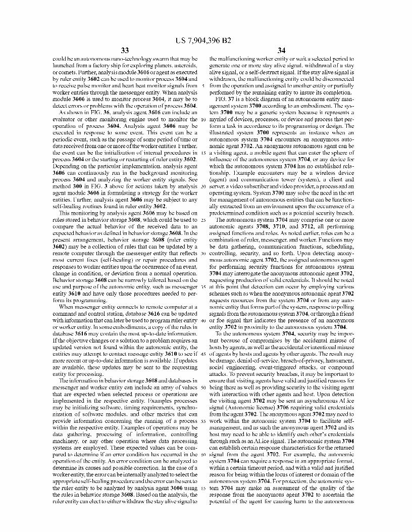
US 7,904,396 B233
34could be an autonomous nano-technology swarm that may be the malfunctioning worker entity or wait a selected period tolaunched from a factory ship for exploring planets, asteroids, generate one or more stay alive signal, withdrawal of a stayor comets. Further, analysis module 3606 or agent as executed
alive signal, or a self-destruct signal. If the stay alive signal is
by ruler entity 3602 can be used to monitor process 3604 and
withdrawn, the malfunctioning entity could be disconnectedto receive pulse monitor and heart beat monitor signals from 5 from the operation and assigned to another entity or partiallyworker entities through the messenger entity. When analysis performed by the remaining entity to insure its completion.module 3606 is used to monitor process 3604, it may be to
FIG. 37 is a block diagram of an autonomous entity man-
detect errors or problems with the operation of process 3604. agement system 3700 according to an embodiment. The sys-As shown in FIG. 36, analysis agent 3606 can include an tem 3700 may be a generic system because it represents a
evaluator or other monitoring engine used to monitor the io myriad of devices, processes, or device and process that per-operation of process 3604. Analysis agent 3606 may be
form a task in accordance to its programming or design. The
executed in response to some event. This event can be a
illustrated system 3700 represents an instance when anperiodic event, such as the passage of some period of time or autonomous system 3704 encounters an anonymous auto-data received from one or more of the worker entities. Further, nomic agent 3702. An anonymous autonomous agent can bethe event can be the initialization of internal procedures in 15 a visiting agent, a mobile agent that can enter the sphere ofprocess 3604 or the starting or restarting of ruler entity 3602. influence of the autonomous system 3704, or any device forDepending on the particular implementation, analysis agent which the autonomous system 3704 has no established rela-3606 can continuously run in the background monitoring tionship. Example encounters may be a wireless deviceprocess 3604 and analyzing the worker entity signals. See
(agent) and communication tower (system), a client and
method 300 in FIG. 3 above for actions taken by analysis 20 server, a video subscriber andvideo provider, aprocess and anagent module 3606 in formulating a strategy for the worker operating system. System 3700 may solve the need in the artentities. Further, analysis agent 3606 may be subject to any
for management of autonomous entities that can be function-
self-healing routines found in ruler entity 3602. ally extracted from an environment upon the occurrence of aThis monitoring by analysis agent 3606 may be based on predetermined condition such as a potential security breach.
rules stored in behavior storage 3608, which could be used to 25 The autonomous system 3704 may comprise one or morecompare the actual behavior of the received data to an autonomic agents 3708, 3710, and 3712, all performingexpected behavior as defined in behavior storage 3608. In the assigned functions and roles. As noted earlier, roles can be apresent arrangement, behavior storage 3608 (ruler entity combination of ruler, messenger, and worker. Functions may3602) may be a collection of rules that can be updated by a
be data gathering, communication functions, scheduling,
remote computer through the messenger entity that reflects 30 controlling, security, and so forth. Upon detecting anony-most current fixes (self-healing) or repair procedures and
mous autonomic agent 3702, the assigned autonomous agent
responses to worker entities upon the occurrence of an event, for performing security functions for autonomous systemchange in condition, or deviation from a normal operation. 3704 may interrogate the anonymous autonomic agent 3702,Behavior storage 3608 can be narrowly tailored based on the requesting production of valid credentials. It should be noteduse and purpose of the autonomic entity, such as messenger 35 at this point that detection can occur by employing variousentity 3610 and have only those procedures needed to per- schemes such as when the anonymous autonomic agent 3702form its programming. requests resources from the system 3704 or from any auto-
When messenger entity connects to remote computer at a nomic entity that forms part of the system, response to pollingcommand and control station, database 3616 can be updated
signals from the autonomous system 3704, or through a friend
with information that can later be used to program ruler entity 40 or foe signal that indicates the presence of an anonymousor worker entity. In some embodiments, a copy of the rules in entity 3702 in proximity to the autonomous system 3704.database 3616 may contain the most up-to-date information. To the autonomous system 3704, security may be impor-If the objective changes or a solution to a problem requires an tant because of compromises by the accidental misuse ofupdated version not found within the autonomic entity, the
hosts by agents, as well as the accidental or intentional misuse
entities may attempt to contact message entity 3610 to see if 45 of agents by hosts and agents by other agents. The result maymore recent or up-to-date information is available. If updates
be damage, denial-of-service, breach-of-privacy, harassment,
are available, these updates may be sent to the requesting social engineering, event-triggered attacks, or compoundentity for processing. attacks. To prevent security breaches, it may be important to
The information in behavior storage 3608 and databases in ensure that visiting agents have valid and justified reasons formessenger and worker entity can include an array of values 5o being there as well as providing security to the visiting agentthat are expected when selected process or operations are with interaction with other agents and host. Upon detectionimplemented in the respective entity. Examples processes the visiting agent 3702 may be sent an asynchronous Alicemay be initializing software, timing requirements, synchro- signal (Autonomic license) 3706 requiring valid credentialsnization of software modules, and other metrics that can
from the agent 3702. The anonymous agent 3702 may need to
provide information concerning the running of a process 55 work within the autonomic system 3704 to facilitate self-within the respective entity. Examples of operations may be management, and as such the anonymous agent 3702 and itsdata gathering, processing of information, controlling
host may need to be able to identify each other's credentials
machinery, or any other operation where data processing through such as an Alice signal. The autonomic system 3704systems are employed. These expected values can be com- can establish certain response characteristics for the returnedpared to determine if an error condition has occurred in the 60 signal from the agent 3702. For example, the autonomicoperation of the entity. An error condition can be analyzed to system 3704 can require a response in an appropriate format,determine its causes and possible correction. In the case of a within a certain timeout period, and with a valid and justifiedworker entity, the error canbe internally analyzed to select the reason for being within the locus of interest or domain of theappropriate self-healing procedure and the error can be sent to autonomous system 3704. For protection, the autonomic sys-the ruler entity to be analyzed by analysis agent 3606 using 65 tern 3704 may make an assessment of the quality of thethe rules in behavior storage 3608. Based on the analysis, the response from the anonymous agent 3702 to ascertain theruler entity can elect to either withdraw the stay alive signal to potential of the agent for causing harm to the autonomous

US 7,904,396 B235
system 3704. Based on this determination the autonomoussystem 3704 can control the type of interaction with the agent3702. The agent can be destroyed, blocked, partially blocked,stay alive signal withdrawn, or allowed to communicate withother agents within the autonomous system 3704. The pro-tection can be triggered at any level of infraction or by acombination of infractions by the anonymous autonomousagent 3702 when responding to the Alice signal. If the agent3702 fails to identify itself appropriately following an Aliceinterrogation, the agent 3702 may be blocked from the systemand given either a self-destruct signal, or its "stay alive"reprieve is withdrawn. The consequence of an unacceptableresponse by an anonymous agent 3702, should it fail to do sowithin a timeout period, may be that the agent 3702 may bedetermined to be an intruder or other invalid agent (process)and consequently it is destroyed and/or excluded from com-municating with other agents 3708, 3710, 3712 in the system.As an alternative to the Alice signal, a quiesce signal, com-mand or instruction can be sent. The quiesce signal is dis-cussed in more detail in conjunction with FIGS. 5, 6 and 24.
FIG. 38 is a hierarchical chart of an autonomous entitymanagement system 3800, according to an embodiment.Properties that a system may possess in order to constitute anautonomic system are depicted in the autonomous entitymanagement system 3800.
General properties of an autonomic (self-managing) sys-tem may include four objectives defined by InternationalBusiness Machines 3802: self-configuring 3804, self-healing3806, self-optimizing 3808 and self-protecting 3810, andfour attributes 3812: self-awareness 3814, environment-awareness 3816, self-monitoring 3818 and self-adjusting3820. One skilled in the art will recognize that other proper-ties also exist, such as self-quiescing 3825. Essentially, theobjectives 3802 could represent broad system requirements,while the attributes 3812 identify basic implementationmechanisms.
Self-configuring 3804 may represent an ability of the sys-tem 3800 to re-adjust itself automatically; this can simply bein support of changing circumstances, or to assist in self-healing 3806, self-optimization 3808 or self-protection 3810.Self-healing 3806, in reactive mode, is a mechanism con-cerned with ensuring effective recovery when a fault occurs,identifying the fault, and then, where possible, repairing it. Inproactive mode, the self-healing 3806 objective may monitorvital signs in an attempt to predict and avoid "health" prob-lems (i.e. reaching undesirable situations).
Self-optimization 3808 may mean that the system 3800 isaware of ideal performance of the system 3800, can measurecurrent performance of the system 3800 against that ideal,and has defined policies for attempting improvements. Thesystem 3800 can also react to policy changes within thesystem as indicated by the users. A self-protecting 3810 sys-tem 3800 can defend the system 3800 from accidental ormalicious external attack, which necessitates awareness ofpotential threats and a way of handling those threats.
Self-managing objectives 3802 may require awareness ofan internal state of the system 3800 (i.e. self-aware 3814) andcurrent external operating conditions (i.e. environment-aware3816). Changing circumstances can be detected through self-monitoring and adaptations are made accordingly (i.e. self-adjusting 3820). Thus, system 3800 may have knowledge ofavailable resources, components, performance characteris-tics and current status of the system, and the status of inter-connections with other systems, along with rules and policiesof therein can be adjusted. Such ability to operate in a hetero-
36geneous environment may require the use of open standardsto enable global understanding and communication withother systems.
These mechanisms may not be independent entities. For5 instance, if an attack is successful, this may include self-
healing actions, and a mix of self-configuration and self-optimisation, in the first instance to ensure dependability andcontinued operation of the system, and later to increase the
10 self-protection against similar future attacks. Finally, theseself-mechanisms could ensure there is minimal disruption tousers, avoiding significant delays in processing.
Other self * properties have emerged or have been revisitedin the context of autonomicity. We highlight some of these
15 briefly here. Self-* 3822 may be self-managing properties, asfollows. Self-anticipating is an ability to predict likely out-comes or simulate self-* actions. Self-assembling is anassembly of models, algorithms, agents, robots, etc.; self-assembly is often influenced by nature, such as nest construc-
20 tion in social insects. Self-assembly is also referred to asself-reconfigurable systems. Self-awareness is "know thy-self' awareness of internal state; knowledge of past states andoperating abilities. Self-chop is the initial four self-properties(Self-Configuration 3804, Self-Healing 3806, Self-Optimisa-
25 tion 3808 and Self-Protection 3810). Self-configuring is anability to configure and re-configure in order to meet policies/goals. Self-critical is an ability to consider if policies arebeing met or goals are being achieved (alternatively, self-reflect). Self-defining is a reference to autonomic event mes-
so sages between Autonomic Managers: contains data and defi-nition of that data-metadata (for instance using XML). Inreference to goals/policies: defining these (from self-reflec-tion, etc.). Self-governing is autonomous: responsibility forachieving goals/tasks. Self-healing is reactive (self-repair of
ss faults) and Proactive (predicting and preventing faults). Self-installing is a specialized form of self-configuration install-ing patches, new components, etc or re-installation of anoperating system after a major crash. Self-managing isautonomous, along with responsibility for wider self-* man-
4o agement issues. Self-optimizing is optimization of tasks andnodes. Self-organized is organization of effort/nodes; par-ticularly used in networks/communications. Self-protectingis an ability of a system to protect itself. Self-reflecting is anability to consider if routine and reflex operations of self-*
45 operations are as expected and can involve self-simulation totest scenarios. Self-similar is self-managing components cre-ated from similar components that adapt to a specific task, forinstance a self-managing agent. Self-simulation is an abilityto generate and test scenarios, without affecting the live sys-
So tem. Self-aware is self-managing software, firmware andhardware.
FIG. 39 is a block diagram of an autonomic element 3900,according to an embodiment. Autonomic element 3900 may
55 include an element 3902 that is operably coupled to sensorsand 3904 and effectors 3906.
Autonomic element 3900 may also include componentsthat monitor 3908, execute 3910, analyze 3912 and plan3914; those components may access knowledge 3916. Those
60 components can interact with sensors 3918 and effectors3920.
FIG. 40 is a block diagram of autonomy and autonomicity4000 at a high system level, according to an embodiment. Ahigh level perspective for an intelligent machine design is
65 depicted in FIG. 40. This diagram of autonomy and autono-micity 4000 includes intelligent machine design and systemlevel autonomy and autonomicity.

US 7,904,396 B237
38FIG. 40 describes three levels for the design of intelligent managed, and the autonomic element 4100 may further
systems:
include an autonomic manager (AM), not shown. The AM1) Reaction 4002 the lowest level, where no learning may be responsible for the MC 4102 within theAE 4100. The
occurs but there is immediate response to state information
AM can be designed as part of the component or providedcoming from sensory systems 4004. 5 externally to the component, as an agent, for instance. Inter-
2) Routine 4006 middle level, where largely routine action of the autonomic element 4100 can occur with remoteevaluation and planning behaviors take place. Input is
(external) autonomic managers (cf. the autonomic communi-
received from sensory system 4004 as well as from the reac- cations channel 4106) through virtual, peer-to-peer, client-tion level and reflection level. This level of assessment results server or grid configurations.in three dimensions of affect and emotion values: positive 10 An important aspect of the architecture of many autonomicaffect, negative affect, and (energetic) arousal. systems can be sensors and effectors, such as shown in FIG.
3) Reflection 4008 top level, receives no sensory 4004
39. A control loop 4108 can be created by monitoring 4110input or has no motor 4010 output; input is received from
behavior through sensors, comparing this with expectations
below. Reflection is a meta-process, whereby the mind delib- (knowledge 3916, as in historical and current data, rules anderates about itself. Essentially, operations at this level look at 15 beliefs), planning 4112 what action is necessary (if any), andthe system's representations of its experiences, its current
then executing that action through effectors. The closed loop
behavior, its current environment, and so forth. of feedback control 4108 can provide a basic backbone struc-As illustrated, input from, and output to, the environment
ture for each system component. FIG. 41 describes at least
may only take place within the reaction 4002 and routine two control loops in the autonomic element 4100, one for4006 layers. One can consider that reaction 4002 level essen- 20 self-awareness 4114 and another 4108 for environmentaltially sits within the "hard" engineering domain, monitoring awareness.the current state of both the machine and its environment, In some embodiments, the self-monitor/self-adjuster con-with rapid reaction to changing circumstances; and, that the trol loop 4114 can be substantially similar to the monitor,reflection 4002 level can reside within an artificial domain analyze, plan and execute (MAPS) control loop described inutilizing its techniques to consider the behavior of the system 25 FIG. 39. The monitor-and-analyze parts of the structure canand learn new strategies. The routine 4006 level can be a perform a function of processing information from the sen-cooperative mixture of both. The high-level intelligent sors to provide both self-awareness 4114 and an awarenessmachine design may be appropriate for autonomic systems as
4108 of the external environment. The plan-and-execute partsdepicted here in FIG. 40, in consideration of the dynamics of
can decide on the necessary self-management behavior that
responses including reaction 4002 and also for reflection 30 will be executed through the effectors. The MAPE compo-4008 of self-managing behavior. nents can use the correlations, rules, beliefs, expectations,
As depicted autonomic computing can reside within the
histories, and other information known to the autonomic ele-domain of the reaction 4002 layer as a result of a metaphoric ment, or available to it through the knowledge repositorylink with the autonomic biological nervous system, where no
3916 within the AM 4104.
conscious or cognitive activity takes place. Other biologi- 35 A reflection component 4116 may perform analysis com-cally-inspired computing (also referred to as nature-inspired
putation on the AE 4100 (cf. the reflection component 4116
computing, organic computing, etc.) may provide such higher within the autonomic manager). In terms of an autonomiclevel cognitive approaches for instance as in swarm intelli- system, reflection can be particularly helpful in order to allowgence. Within the autonomic computing research community, the system to consider the self-managing policies, and toautonomicity may not normally be considered to imply this 40 ensure that the policies are being performed as expected. Thi snarrower view. Essentially, the autonomic self-managing may be important since autonomicity involves self-adapta-metaphor can be considered to aim for a user/manager to be tion to the changing circumstances in the environment. Anable to set high-level policies, while the system achieves the autonomic manager communications (AM/AM) componentgoals. Similar overarching views exist in other related initia- 4118 can also produce a reflex signal 4120. A self adjustertives and, increasingly, they are influencing each other. 45 4122 can be operably coupled to a self-monitor 4124 in the
In terms of autonomy and autonomicity, autonomy can be self control loop 4114.considered as being self-governing while autonomicity canbe considered being self-managing. At the element level, an
CONCLUSIONelement may have some autonomy and autonomic properties,since to self-manage implies some autonomy, while to pro- 50 The systems, methods and apparatus disclosed herein pro-vide a dependable autonomous element requires such auto- vide autonomic environmental safety devices, such as smokenomic properties as self-healing along with the element's
detectors, that may be associated in a heuristic neural systemself-directed task. From this perspective, it would appear that
(FINS) architecture in which a heart beat monitor signal and a
the separation of autonomy and autonomicity as characteris- reflex signal may be exchanged between devices in the FINStics will decrease in the future and eventually will become 55 so that stay-alive signals and stay-awake signals to thenegligible. On the other hand, at the system level if one
devices can be controlled in ways that provide more reliableconsiders again the three tiers of the intelligent machine alerts of environmental danger.design (reaction 4002, routine 4006, and reflection 4008) and
Although specific embodiments have been illustrated and
accepts the narrower view of autonomicity, there is a potential
described herein, it will be appreciated by those of ordinarycorrelation between the levels. That is, the reaction 4002 level 60 skill in the art that any arrangement which is calculated tocorrelates with autonomicity, and the reflection 4008 level
achieve the same purpose may be substituted for the specific
correlates with autonomy; autonomy as in self-governing of
embodiments shown. This application is intended to coverthe self-managing policies within the system. any adaptations or variations. For example, although
FIG. 41 is a block diagram of an architecture of an auto- described in procedural terms, one of ordinary skill in the artnomic element (AE) 4100 according to an embodiment that 65 will appreciate that implementations can be made in anincludes reflection and reflex layers. The autonomic element object-oriented design environment or any other design envi-4100 may include a managed component (MC) 4102 that is ronment that may provide the required relationships.

US 7,904,396 B239
In particular, one of skill in the art will readily appreciatethat the names of the methods and apparatus may be notintended to limit embodiments. Furthermore, additionalmethods and apparatus can be added to the components,functions can be rearranged among the components, and newcomponents to correspond to future enhancements and physi-cal devices used in embodiments can be introduced withoutdeparting from the scope of embodiments. One of skill in theart will readily recognize that embodiments are applicable tofuture communication devices, different file systems, andnew environmental safety devices.
The terminology used in this application is meant toinclude all environments and alternate technologies whichprovide the same functionality as described herein.
We claim:1. A computer-accessible medium in a first autonomic
environmental safety device, the computer-accessiblemedium having executable instructions of autonomic com-munication, the executable instructions capable of directing aprocessor of the first autonomic environmental safety deviceto perform:
receiving a quiesce instruction from a second autonomicenvironmental safety device; and
invoking a function of a quiesce component of the firstautonomic environmental safety device, wherein thefunction of the quiesce component comprises deactivat-ing the first autonomic environmental safety device, andthen, if the first autonomic environmental safety devicedoes not receive a stay-alive reprieve signal after a pre-determined period of time, the first autonomic environ-mental safety device self-destructs.
2. The computer-accessible medium of claim 1, whereinthe autonomic environmental safety device comprises asmoke detector.
3. The computer-accessible medium of claim 1, whereintransmitting environment health/urgency data is performedbefore transmitting self health/urgency data.
4. The computer-accessible medium of claim 1, whereintransmitting environment health/urgency data is performedsimultaneously with transmitting self health/urgency data.
5. The computer-accessible medium of claim 1, whereinthe executable instructions further comprise transmitting theenvironment health/urgency data and the self health/urgencydata together.
6. The computer-accessible medium of claim 5, whereinthe executable instructions further comprise encapsulatingthe environment health/urgency data and the self health/ur-gency data in a packet.
7. The computer-accessible medium of claim 1, themedium further comprising executable instructions capableof directing the processor to perform transmitting event mes-sages.
8. The computer-accessible medium of claim 1, themedium further comprising executable instructions capableof directing the processor to perform:
receiving self health/urgency data from a self control loopcomponent of the autonomic environmental safetydevice.
9. The computer-accessible medium of claim 1, themedium further comprising executable instructions capableof directing the processor to perform:
receiving environment health/urgency data from an envi-ronment control loop component of the autonomic envi-ronmental safety device.
10. An autonomic environmental safety device, the auto-nomic environmental safety device comprising:
40a self-monitor that is operable to receive information from
sensors and operable to monitor and analyze the sensorinformation and access a knowledge repository;
a self-adjuster operably coupled to the self-monitor in a5 self control loop, the self adjuster operable to access the
knowledge repository, the self adjuster operable to trans-mit data to effectors, and self adjuster operable to planand execute;
an environment-monitor that is operable to receive infor-10 mation from the sensors and operable to monitor and
analyze the sensor information and access the knowl-edge repository;
an autonomic manager communications component oper-ably coupled to the environment-monitor in an environ-
15 ment control loop, the autonomic manager communica-tions component being operable to access theknowledge repository, and to produce and transmit apulse monitor signal, the pulse monitor signal includinga heart beat monitor signal and a reflex signal, the reflex
20 signal including self health/urgency data and environ-ment health/urgency data; and
a quiescing component operably coupled to the self-moni-tor, the quiescing component receiving a quiescenceinstruction from another autonomic environmental
25 safety device, the quiescing component withdrawing astay-awake signal, if the first autonomic environmentalsafety device does not receive a stay-alive reprieve sig-nal after a predetermined period of time, the first auto-nomic environmental safety device self-destructs.
30 11. The autonomic environmental safety device of claim10, wherein the autonomic environmental safety device fur-ther comprises a smoke detector.
12. The autonomic environmental safety device of claim10, wherein the self health/urgency data further comprises
35 uncompressed self health/urgency data, andwhereinthe envi-ronment health/urgency data further comprises uncom-pressed environment health/urgency data.
13. The autonomic environmental safety device of claim10, wherein the autonomic manager communications com-
40 ponent is further operable to transmit the environment health/urgency data and the self health/urgency data together.
14. The autonomic environmental safety device of claim13, wherein the autonomic manager communications com-ponent is further operable to encapsulate the environment
45 health/urgency data and the self health/urgency data in apacket.
15. The autonomic environmental safety device of claim10, wherein the pulse monitor signal further comprises at
50 least one of an urgency signal, environmental condition, andan event condition.
16.A method for managing a first smoke detector based ona functioning state and an operating status of the smokedetector, the method comprising:
55 receiving a quiesce instruction from a second smoke detec-tor;
invoking a function of a quiesce component of the firstsmoke detector, wherein the function of the quiescecomponent comprises deactivating the first smoke
60 detector, and then, if the first smoke detector does notreceive a stay-alive reprieve signal after a predeterminedperiod of time, the first smoke detector self-destructs;
generating one or more stay-awake signal based on thefunctioning state and operating status of the first smoke
65 detector.17. The method of claim 16, wherein the generating one or
more stay-awake signal is based on processing received sig-

US 7,904,396 B241
nals from the smoke detector indicative of functioning stateand operating status to obtain an analysis of the condition ofthe smoke detector.
18. The method of claim 16, wherein the functioning stateof the smoke detector comprises one or more on signal, off 5
signal, active signal, and inactive signal.19. The method of claim 16, wherein the operating status of
the smoke detector comprises one or more urgency signal,reflex signal, environmental condition, and event condition.
20. The method of claim 19, wherein an event condition 10
further comprises one or more incorrect operation, emergentbehavior, failure to perform self healing, and likelihood ofjeopardizing primary objectives.
21. An autonomic system, the autonomic system compris- 15
ing:a plurality of autonomic environmental safety devices per-
forming one or more programmed tasks;a coordinating autonomic environmental safety device for
assigning programmed tasks and for issuing instructions 20
to the plurality of autonomic environmental safetydevices;
a messenger autonomic environmental safety device forfacilitating communication among the coordinatingautonomic environmental safety device, plurality of 25
autonomic environmental safety devices, and a remotesystem;
wherein one or more programmed tasks performed by theplurality of autonomic environmental safety device isgenerating signals indicative of functional state and 30
operating status;wherein the coordinating autonomic environmental safety
device based on the generated signals emits a stay-awake signal to one or more of the plurality of auto-nomic environmental safety devices, and then, if the at 35
least one autonomic environmental safety device doesnot receive the stay-awake signal after a predeterminedperiod of time, the at least one autonomic environmentalsafety device self-destructs, and
wherein the coordinating autonomic environmental safety 40
device based on the generated signals emits a quiescesignal to one or more of the plurality of autonomicenvironmental safety devices.
22. The autonomic system of claim 21, wherein the plural- 45
ity of autonomic environmental safety devices further com-prises a plurality of smoke detectors.
23. The autonomic system of claim 21, where in the func-tioning state of the system comprises one or more on signal,off signal, active signal, and inactive signal. 50
24. The autonomic system of claim 23, wherein the oper-ating status of the system comprises one or more urgencysignal, reflex signal, environmental condition, and event con-dition.
25. The autonomic system of claim 24, wherein an event 55
condition further comprises one or more incorrect operation,emergent behavior, failure to perform self healing, and like-lihood of jeopardizing primary objectives.
26. An autonomous system, the autonomous system com-prising: 60
a first autonomic environmental safety device composed ofself-similar autonomic components;
a second autonomic environmental safety device com-posed of self-similar autonomic components; 65
a third autonomic environmental safety device composedof self-similar autonomic components;
42wherein the third autonomic environmental safety device
facilitates communication between the first autonomicenvironmental safety device and the second autonomicenvironmental safety device;
wherein the first autonomic environmental safety devicegenerates a heart beat monitor signal and pulse monitorsignal;
wherein the second autonomic environmental safetydevice generates a stay- awake signal based on the gen-erated heartbeat monitor signal and pulse monitor signalfrom the first autonomic environmental safety device,and then, if the first autonomic environmental safetydevice does not receive a stay-awake signal after a pre-determined period of time, the first autonomic environ-mental safety device self-destructs, and
wherein the second autonomic environmental safetydevice generates a quiesce signal based on the generatedheart beat monitor signal and pulse monitor signal fromthe first autonomic environmental safety device.
27. The autonomous system of claim 26, wherein eachautonomic environmental safety device comprises a first plu-rality of neural basis functions and a first evolvable neuralinterface operably coupled to each of the first plurality ofneural basis functions.
28. The autonomous system of claim 26, wherein each ofthe autonomic environmental safety devices comprises asmoke detector.
29. A computer-accessible medium having executableinstructions to construct an environment of an autonomicenvironmental safety device to satisfy increasingly demand-ing external requirements, the executable instructionscapable of directing a processor to perform:
instantiating a first embryonic evolvable neural interface;evolving the first embryonic evolvable neural interface
towards complex complete connectivity;wherein the evolvable neural interface receives one or
more heart beat monitor signal, pulse monitor signal,and quiesce signal,
wherein the evolvable neural interface generates one ormore heart beat monitor signal, pulse monitor signal,and quiesce signal,
wherein the quiesce signal comprises a stay-awake signal,wherein the first embryonic evolvable neural interface
receives the quiesce signal from a second embryonicevolvable neural interface to withdraw a stay-awake sig-nal, and then, if the first embryonic evolvable neuralinterface does not receive a stay-alive reprieve signalafter a predetermined period of time, the first embryonicevolvable neural interface self-destructs.
30. The computer-accessible medium of claim 29, whereinthe autonomic environmental safety device further comprisesa smoke detector.
31. The computer-accessible medium of claim 29, whereinthe embryonic evolvable neural interface further comprises aneural thread possessing only minimal connectivity.
32. A computer-accessible medium having executableinstructions to protect an autonomic system, the executableinstructions capable of directing a processor of the autonomicsystem to perform:
sending a quiesce signal to a first autonomic environmentalsafety device from a second autonomic environmentalsafety device;
monitoring the response of the autonomic environmentalsafety device to the quiesce signal;
determining the autonomic environmental safety devicepotential for causing harm to the autonomic system, and

US 7,904,396 B243
controlling the autonomic system based on the autonomicenvironmental safety device potential for causing harmto the autonomic system,
wherein controlling the autonomic system further com-prises blocking the autonomic environmental safetydevice from accessing certain resources, and generatinga signal to the autonomic environmental safety device totransmit the autonomic environmental safety devicestay-awake, and
wherein a quiesce signal is a request for the autonomicenvironmental safety device to deactivate the autonomicenvironmental safety device, if the first autonomic envi-ronmental safety device does not receive a stay-alivereprieve signal, the first autonomic environmental safetydevice self-destructs.
33. The computer-accessible medium of claim 32, whereinthe autonomic environmental safety device comprises asmoke detector.
34. The computer-accessible medium of claim 32, whereincontrolling the autonomic system further comprises:
generating a signal to the autonomic environmental safetydevice to withdraw the autonomic environmental safetydevice stay-awake.
35. A computer system for protecting an autonomic sys-tem, the computer system comprising:
a processor;a storage device coupled to the processor; and
44software operative on the processor for:
(i) sending a quiesce signal to an autonomic environ-mental safety device from a second autonomic envi-ronmental safety device;
5 (ii) monitoring the response of the autonomic environ-mental safety device to the quiesce signal;
(iii) determining the autonomic environmental safetydevice potential for causing harm to the autonomicsystem, and
10 (iv) controlling the autonomic system in reference topotential of the autonomic system to cause harm to theautonomic system, wherein controlling the auto-nomic system further comprises withdrawing theautonomic environmental safety device stay-awake,
15 wherein controlling the autonomic system is blockingthe autonomic environmental safety device fromaccessing certain resources, and
wherein the quiesce signal is a request for the autonomicenvironmental safety device to deactivate itself, and
20 then, if the first autonomic environmental safetydevice does not receive a stay-alive reprieve signal,the first autonomic environmental safety device self-destructs.
36. The computer system of claim 35, wherein the auto-25 nomic environmental safety device further comprises a
smoke detector.