united states patent and trademark …€™s chemical research and development section. ......
TRANSCRIPT

UNITED STATES PATENT AND TRADEMARK OFFICE
________________________________
BEFORE THE PATENT TRIAL AND APPEAL BOARD
________________________________
HALLIBURTON ENERGY SERVICES, INC.,PETITIONER,
v.
SCHLUMBERGER TECHNOLOGY CORPORATION,
PATENT OWNER.
________________________________
CASE IPR2017-01568PATENT 8,167,043
________________________________
DECLARATION OF BRADLEY LEON TODD UNDER 37C.F.R. § 1.68 IN SUPPORT OF PETITION FOR INTER
PARTES REVIEW OF U.S. PATENT NO. 8,167,043
Page 1 of 65 Halliburton Energy Services, Inc.Exhibit 1002

TABLE OF CONTENTS
I. Introduction......................................................................................................2
II. Background Qualifications ..............................................................................5
III. Understanding of Patent Law ........................................................................11
IV. Level of Ordinary Skill in the Pertinent Art..................................................13
V. The ‘043 Patent..............................................................................................15
VI. Background on State of Technology in the Field of the Invention ...............16
VII. Background on the Prior Art References.......................................................28
VIII. Broadest Reasonable Interpretation...............................................................32
IX. The Challenged Claims are Unpatentable .....................................................33
X. Conclusion .....................................................................................................64
Page 2 of 65 Halliburton Energy Services, Inc.Exhibit 1002
I. Introduction
I, Bradley Leon Todd, declare as follows:
1. I have been retained on behalf of Halliburton Energy Services, Inc.
(“Petitioner” or “Halliburton”) to provide expert opinions in connection with
an inter partes review (“IPR”) of U.S. Patent No. 8,167,043 (“the ‘043
patent”).
2. I am over 18 years of age. I have personal knowledge of the facts and opinions
stated in this Declaration and could testify competently to them if asked to do
so.
3. I am being compensated for my time in connection with this IPR at my
standard consulting rate of $300 per hour. My compensation is not dependent
upon the opinions that I am providing in this declaration. While I own some
stock in Petitioner’s parent company, Halliburton Corporation, that stock does
not represent a substantial portion of my net worth, nor do I expect the
outcome of this proceeding to have any impact on my finances.
4. I have been asked to provide my opinions regarding whether claims 1-4, 6, 7,
13, 15, and 25-27 of the ‘043 patent (“the Challenged Claims”) are invalid as
anticipated or obvious to a person having ordinary skill in the art at the time of
the alleged invention. As indicated below, it is my opinion that a person
Page 3 of 65 Halliburton Energy Services, Inc.Exhibit 1002

having ordinary skill in the art at the time of the alleged invention would find
all of these claims to be anticipated or rendered obvious.
5. The ‘043 patent was filed on August 8, 2008 as U.S. Application No.
12/126,501 and indicates that it is a division of U.S. Application No.
11/294,983, which was filed December 5, 2005.
6. For the purposes of this Declaration, I have been asked to assume that the date
of the alleged invention recited in the ‘043 patent is December 5, 2005, which
is the date U.S. Application No. 11/294,983 was filed. However, my opinions
that one of skill in the art would find claims 1-4, 6, 7, 13, 15, and 25-27 to be
rendered obvious would remain the same even if the date of the alleged
invention were later, including up to August 8, 2008, which is the date the
‘043 patent was filed.
7. The face of the ‘043 patent names Dean Willberg, Marina Bulova,
Christopher Fredd, Alexey Vostrukhov, Curtis Boney, John Lassek, Ann
Hoefer, and Philip Sullivan as the inventors for the ‘043 patent, and identifies
Schlumberger Technology Corporation as the named assignee.
8. In preparing this Declaration, my opinion is based, at least in part, on
reviewing the following documents, which I understand will be given the
exhibit numbers referenced below in this Proceeding:
Page 4 of 65 Halliburton Energy Services, Inc.Exhibit 1002

Reference Exhibit # Name
U.S. Patent No. 7,775,278 1001 “ ‘278 patent”
Partial Prosecution File History of ‘278
patent1007 “ ‘278 File History”
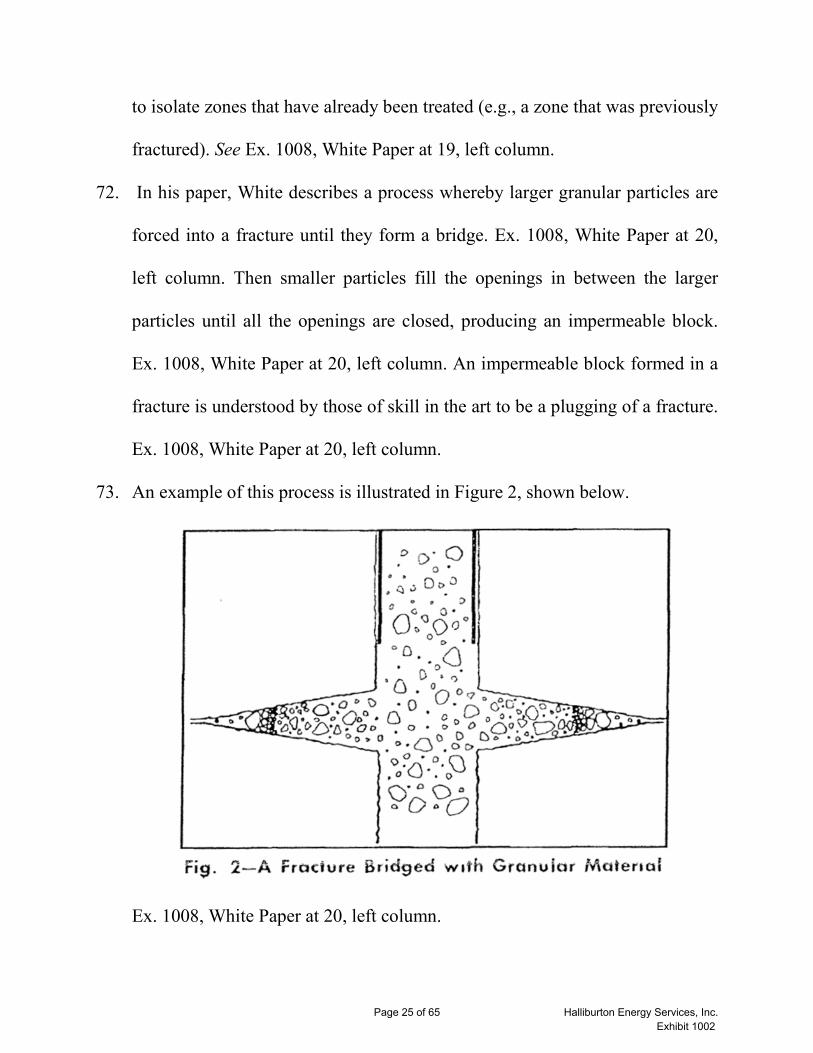
U.S. Patent No. 4,716,964 to Erbstoesser 1004 “Erbstoesser”
U.S. Patent No. 3,353,604 to Gibson 1006 Gibson
White, Garland, “The Use of Temporary
Blocking Agents in Fracturing and
Acidizing Operations,” BJ Services
Spring Meeting of the Pacific Coast
District, Division of Production, Los
Angeles, CA, May 1958
1008 White
Harrison, N.W., “Diverting Agents –
History and Application,” Society of
Petroleum Engineers (SPE) Paper #
3653, May, 1972
1009 “Harrison”
“New ‘beads’ help acidizing, fracturing,”
The Oil and Gas Journal, August 30,
1965
1012 “Unibeads Article”
Gruesbeck, C., et al., “Particle Transport
Through Perforations,” Society of
Petroleum Engineers Journal, December
1982
1013 “Gruesbeck”
U.S. Application Pub. No. 2004/0152601
to Still.
1015“Still”
Page 5 of 65 Halliburton Energy Services, Inc.Exhibit 1002

J. Frederic Walker, Formaldehyde, 2nd
Ed., Reinhold Publishing Corporation.
1016“Walker”
II. Background Qualifications
9. I am a mechanical engineer with over 35 years of experience in the oil and gas
industry. I received a BS in mechanical engineering from Oklahoma State
University in 1981. Attached to this declaration is a copy of my CV. See Ex.
1003.
10. From 1981 to 1986, I worked in the Instrumentation and Controls group and
in the Heavy Equipment group at Halliburton’s Duncan Technology Center
(DTC), in the Mechanical Research and Development (MRD) Section. At the
time, there were two main sections at DTC, Chemical Research and
Development (CRD) and MRD. MRD was made up of three groups, the
Instrumentation and Control Group, the Heavy Equipment Group, and the
Pump Group.
11. The Instrumentation and Controls Group dealt with sensors for pressure,
temperature, liquid flow rate, mass flow rate, viscosity, density, pH, proppant
concentration, as well as liquid and powder additive systems, engine and
pump controls, data recording and transmission, display screens and devices,
digital-to-analog conversion (and vice versa), proportional-integral-derivative
(PID) controllers, and the like.
Page 6 of 65 Halliburton Energy Services, Inc.Exhibit 1002
12. The Heavy Equipment group worked on the design of pump trucks and skids,
blenders, manifolding, power trains, hydraulics, and bulk handling equipment.
13. The Pump Group worked on the design of high pressure fracturing and
cementing pumps as well as the low pressure transfer pumps (centrifugal
pumps).
14. Depending on the project, it was very common to work on product
development efforts that straddled one or more groups, or one or more
sections. For example, an engineer in the Instrumentation and Control Group
may be working on an additive pump for cementing that was timed off of the
pump input shaft. A project like this would require interfacing with CRD
regarding the liquid additive to be metered, such as viscosity, vapor pressure,
corrosiveness, etc. As well, it would likely be necessary to interface with the
Pump Group about input shaft rpm, pump displacement, suction manifold
pressure, etc.
15. During my period in the Instrumentation and Control Group, I worked on a
variety of projects. These included pressure sensors, densometers, flow
meters, metering skids, data recording, pump and engine controls, dry-
additive feeders, mass flow measurement, and data recording vans. These
projects involved applying engineering principles to slurry calculations, slurry
transport, hydraulic horsepower, friction calculation, orifice and nozzle flow,
Page 7 of 65 Halliburton Energy Services, Inc.Exhibit 1002

fluid rheology, material science, stress calculations, electronic signaling and
transfer, and mathematical modeling.
16. During my time in the Heavy Equipment group, opportunities arose to work
on projects involving pump and blender skids/trailers, bulk storage equipment,
manifolding equipment, marine equipment, hydraulic power packs, lifting
equipment and cement handling equipment. These projects allowed the
application of stress calculations, hydraulic flow calculations, pneumatic
conveyance, pipe flow, and introduction into marine architecture calculations
(center of buoyancy, righting moment, etc.).
17. In late 1986, I became involved in a large project with Halliburton to deploy a
spread of equipment to Nigeria, where I obtained substantial experience
working in the field. My field engineering assignments included cementing,
acidizing, sand control, well testing, nitrogen/coil tubing, brine filtration, and
tool services, in addition to the lab responsibilities.
18. As a field engineer I was required to overcome many real world obstacles
through my knowledge of applied chemistry including viscosifying agents,
acid types and reactions, corrosion inhibitors, scale inhibitors, solvents for
wax, brines, surfactants, pH buffers, ion exchange, and all of the chemical
aspects of the formation rock and formation fluids.
Page 8 of 65 Halliburton Energy Services, Inc.Exhibit 1002

19. During the next decade, the majority of my work was spent on international
assignments involving field work. This work required me to continue to
expand my knowledge of chemistry through practical experience, additional
education, and engaging with chemists at Halliburton on issues that arose. I
ultimately established a small chemistry lab at Halliburton’s Port Harcourt
base in Nigeria to assist in my field work.
20. In the 1990s, I worked with Halliburton’s sister company, Otis Engineering
as Regional Technology Advisor for their newly consolidated sand control
services. I was based in Singapore and had responsibility for the Asia/Pacific
and Middle East regions. During this period, I oversaw the deployment of
sand control technology involving gravel packing of vertical or horizontal
wells, as well as services like acid prepacking and hydraulic fracturing.
21. In 1997, I took a position in Duncan, Oklahoma as a Technical Advisor in
Halliburton’s Chemical Research and Development section. During this time,
my work included sand control, acidizing, cementing, water control, drilling
fluids, fracturing, and material issues related to completion tools.
22. Around 2000, I began working on degradable materials, first for sand control
issues, and then on applying them as diverters in fracturing and acidizing
operations. Using degradable materials for sand control and fracturing relies
on the same basic principle of bridging an opening using appropriately sized
Page 9 of 65 Halliburton Energy Services, Inc.Exhibit 1002

particles. From 2000-2010, a substantial portion of my work involved the
research and development of diverter products, including degradable diverting
agents.
23. I left Halliburton in 2012 when the Technology Center moved from Duncan,
Oklahoma to Houston, Texas. At this time, I started Completion Science LLC
to provide material science solutions for well completion applications. At
Completion Science, I oversee a team of engineers and chemists. Our work
focuses on any material science needs for well completion, including
degradable diverting agents and degradable tools.
24. In addition to my practical experience, I have authored or co-authored
numerous oil and gas papers and have been listed as an inventor on many
patents involving the oil and gas field. A selection of these papers and patents
are presented below. A more complete listing can be found in my CV. See Ex.
1003.
Papers
• SPE 39593, “Current Materials and Devices for Control of Fluid Loss,”
published in 1998.
• SPE 86494, “An Innovative System for Complete Cleanup of a Drill-In Fluid
Filter Cake,” published in 2004.
Page 10 of 65 Halliburton Energy Services, Inc.Exhibit 1002
• SPE 102606, “Design and Field Testing of a Truly Novel Diverting Agent,”
published in 2006.
• SPE 149221, “Restim of Wells using Biodegradable Particulates as
Temporary Diverting Agents,” published in 2011.
• SPE 143147, “Fracture-Width Estimation for an Arbitrary Pressure
Distribution in Porous Media,” published 2011.
Patents
• U.S. Patent No. 6,209,646, “Controlling the release of chemical additives in
well treating fluids,” filed April 21, 1999.
• U.S. Patent No. 6,896,058, “Methods of introducing treating fluids into
subterranean producing zones,” filed October 22, 2002.
• U.S. Patent No. 6,971,448, “Methods and compositions for sealing
subterranean zones,” filed February 26, 2003.
• U.S. Patent No. 7,267,170, “Self-degrading fibers and associated methods of
use and manufacture,” filed on January 31, 2005.
• U.S. Patent No. 8,074,715, “Methods of setting particulate plugs in horizontal
well bores using low-rate slurries,” filed on January 15, 2009.
• U.S. Patent No. 8,67,612, “Increasing fracture complexity in ultra-low
permeable subterranean formation using degradable particulate,” filed on
January 15, 2011.
Page 11 of 65 Halliburton Energy Services, Inc.Exhibit 1002

25. Other details concerning my background, professional service, and more, are
set forth in my curriculum vitae. See Ex. 1003.
26. In forming my opinion expressed in this report, I relied on my knowledge,
skill, training, education, and over thirty years of professional experience in
the oil and gas industry.
III. Understanding of Patent Law
27. I am not an attorney, though I have been provided with an understanding of
patent law sufficient to conduct the analysis given in this report. The
following represents my understanding of these issues.
28. A patent or printed publication with a filing date that predates December 5,
2005 is considered to be prior art.
29. A claim of a patent is invalid or unpatentable if that claim is either anticipated
or obvious in view of prior art.
30. I understand that in order to show anticipation of a claim, every element of a
claim must be disclosed expressly or inherently in a single prior art reference,
and arranged in the prior art reference as arranged in the claim. I understand
that, in order to show obviousness of a claim, the claim must be obvious from
the perspective of a person having ordinary skill in the relevant art at the time
the alleged invention was made. I understand that a claim may be obvious in
Page 12 of 65 Halliburton Energy Services, Inc.Exhibit 1002

view of a single reference, or may be obvious from a combination of two or
more prior art references.
31. Obviousness, as I understand, can be established by (for example): combining
prior art elements according to known methods to yield predictable results;
simple substitution of one known element for another to obtain predictable
results; use of known techniques to improve similar devices in the same way;
applying a known technique to a known device ready for improvement to
yield predictable results; choosing from a limited number of identifiable,
predictable solutions with a reasonable expectation of success; known work in
one field of endeavor prompting variations of it for use in either the same field
or a different one based on design incentives or other market forces if the
variations are predictable to one of ordinary skill; or some teaching,
suggestion or motivation in the prior art that would have led one of ordinary
skill to modify the prior art reference or to combine prior art reference
teachings to arrive at the claimed invention.
32. I understand that the obviousness analysis need not seek out precise teachings
directed to the specific subject matter of the challenged claims, but can take
into account ordinary innovation and experimentation, and that one of skill in
the art is a person of ordinary creativity and is not an automaton.
Page 13 of 65 Halliburton Energy Services, Inc.Exhibit 1002
33. Additionally, I understand that analysis of obviousness should not be done in
hindsight, but must be done using the perspective of one of ordinary skill in
the art at the time of the invention.
34. I also understand than an invention that might otherwise be considered
obvious may be considered non-obvious if one or more of the prior art
references provides a clear indication that it discourages or leads away from a
particular combination or modification.
35. Finally, I understand that the burden of proof applied in this proceeding is the
“preponderance of evidence” standard. I understand that this means that
obviousness must be proven to be “more likely than not” in view of the
evidence.
36. I have applied these standards as I understand them to my evaluation of
whether the claims of the ‘043 patent would have been obvious over the prior
art.
IV. Level of Ordinary Skill in the Pertinent Art
37. I understand that a “person of ordinary skill in the art” is a hypothetical person
who is presumed to have known the relevant art at the time of the invention. I
further understand that the relevant timeframe for assessing the ‘043 patent for
purposes of this declaration is prior to December 5, 2005. If I refer to the time
of the invention in this declaration, I am referring to this timeframe.
Page 14 of 65 Halliburton Energy Services, Inc.Exhibit 1002

38. I have been advised that there are multiple factors relevant to determining the
level of ordinary skill in the pertinent art, including the educational level of
active workers in the field at the time of the alleged invention, the
sophistication of the technology, the type of problems encountered in the art,
and the prior art solutions to those problems.
39. The Challenged Claims pertain to a method of treating a well using a
degradable material as a temporary plugging agent.
40. It is my opinion that a person of ordinary skill in the art at the time of the
invention was typically a person who had at least a bachelor’s degree in
petroleum, mechanical, or chemical engineering, or three or more years of
experience using degradable materials with well treatments. I am directly
familiar with the capabilities of such persons of ordinary skill in the art
because I supervised and worked with such persons at the time of the
invention. At the time of the invention, I had at least this level of skill in the
art, having a B.S. in mechanical engineering and over 20 years of experience.
41. In forming the opinions expressed in this Declaration, I relied upon my
education and experience in the relevant field of the art, and have considered
the viewpoint of a person having ordinary skill in the relevant art, as of the
time of the invention.
Page 15 of 65 Halliburton Energy Services, Inc.Exhibit 1002
V. The ‘043 Patent
A. The Prosecution History
42. From the face of the ‘043 patent, it was filed on August 8, 2008 as U.S.
Application No. 12/126,501 (“the ‘501 application”). Ex. 1001, ‘043 Patent.
43. I have reviewed the prosecution history of the ‘501 application, and I am of
the understanding that claims 38-40, 42, 43, 50, 52, 62-65 of the ‘517
application matured into Challenged Claims 1-4, 6, 7, 13, 15, and 25-27 of the
‘043 patent. See Ex. 1007, Prosecution History at 324-326 [12-12-11 claim
amendments].
44. Prior to the allowance of any of the Challenged Claims, however, I understand
that U.S. Patent Publication No. 2003/0060374 to Cooke in view of U.S.
Patent Application 2005/0230107 to McDaniel, among other tertiary
references was presented by the Examiner as having rendered obvious all of
the Challenged Claims. Ex. 1007, Prosecution History at 122-127 [March 25,
2010 Non-final Office action at 8-13].
45. I also understand the Applicant unsuccessfully attempted to argue that Cooke
did not disclose a slurry to form a plug, but rather “introducing a slurry of
polymer particles and tailoring the flow rate into the well to slow to zero or
near zero so that the slurry particles may settle and accumulate in the
wellbore.” Ex. 1007, Prosecution History at 212 [October 26, 2010, Response
Page 16 of 65 Halliburton Energy Services, Inc.Exhibit 1002

at 5]. Further, the Applicant argued that McDaniel described drilling
operations and thus one would not look to such reference for the modification
of Cooke. Ex. 1007, Prosecution History at 212 [October 26, 2010, Response
at 5]; Ex. 1007, Prosecution History at 151 [July 26, 2010, Response at 12].
46. I understand the claims were only allowed after the Applicant amended the
independent claims to include the recitation “and an additive for accelerating
degradation of the degradable material.” Ex. 1007, Prosecution History at
324-326 [December 12, 2011, Response at 2-4], 311-316 [September 12, 2011
Non-final Office action at 2-7], 333-337 [January 24, 2012 Notice of
Allowance].
47. As discussed in detail below, it is my opinion that Erbstoesser in view of Still,
Gibson in view of Walker, and Gibson in view of Erbstoesser and Still teach
all of the limitations of the Challenged Claims, including “an additive for
accelerating degradation of the degradable material.”
VI. Background on State of Technology in the Field of the Invention
A. Fracturing
48. At the time of the alleged invention, and still today, one of the most common
stimulation treatments of a well was hydraulic fracturing, where a fluid is
injected into a well at high pressure until a portion of the formation in contact
with the wellbore fractures under the high pressure. The fracturing fluid would
Page 17 of 65 Halliburton Energy Services, Inc.Exhibit 1002

then be injected into the formation due to the high pressure in the wellbore,
which further extends the fracture.
49. After the fracture is open, proppant is added to the fracturing fluid forming a
slurry, so that the proppant will be injected into the formation as part of the
slurry. The proppant is intended to be distributed throughout the fracture so
that it can keep the fracture propped open once the well bore pressure is
reduced.
50. At some point, the pressure in the wellbore is no longer sufficient to further
extend the fracture or the operator of the well does not desire to extend the
fracture beyond a certain point, so the operator will reduce the pressure in the
wellbore and allow the fracture to partially close.
51. The fracture does not completely close when pressure is reduced because of
the proppants located within the fracture. In the industry, the creating and
propping open of fractures is sometimes referred to as increasing the
permeability of the formation. This increase in permeability through fracturing
allows hydrocarbons to more easily reach the well bore resulting in increased
production of hydrocarbons from a well.
52. To increase production even further, those of skill in the art at the time of the
invention would have known to create more than one fracture. However, a
significant hurdle in doing so is that the fracturing fluid will simply flow into
Page 18 of 65 Halliburton Energy Services, Inc.Exhibit 1002

the existing fracture as it is the path of least resistance. This makes it a
challenge to create enough pressure in the wellbore to induce a second
fracture, let alone additional fractures.
53. By the time of the alleged invention, a well-known solution to this problem
was to block the fracturing fluid from entering existing fractures by using a
physical barrier or plug.
B. Creating a Plug, Bridge, Seal, or Block
54. Some in the art use the terms bridging, sealing, blocking, and plugging
interchangeably depending on the context. When I use these terms in this
declaration I understand them to mean substantially the same in the context
provided by the prior art.
55. At the time of the invention, it was known that a plug could block the entire
wellbore, which would prevent any fluid from entering a fracture beyond the
plug. While effective, this solution is generally too time consuming to
implement for every single fracture, which limits its usefulness.
56. Another solution known at the time of the invention was to plug individual
fracture or perforations in a well casing. This solution takes advantage of the
fact that since fracturing fluid will naturally flow into the most permeable
locations first, the fracturing fluid can be used to carry plugging material
directly to the fractures or perforations that need to be plugged. This solution
Page 19 of 65 Halliburton Energy Services, Inc.Exhibit 1002

was also faster than plugging the entire wellbore since the plugging material
could simply be added to the fracturing fluid as needed.
57. At the time of the invention, applications of using solid particles to bridge
openings and form plugs had been well studied and thus solid particles were
often used to plug fractures and perforations in wells.
58. The basic concept is to choose a particle size such that when one, two or more
of the particles enter the opening at the same time they will get stuck in the
opening. Other particles then build up around these stuck particles until the
opening is completely blocked or plugged. This process is often referred to as
bridging in the art.
59. The physics of particle bridging is extremely well understood by a person of
skill in the art. The reason for this is that using particulates to bridge (and
plug) openings has wide applicability in the Oil & Gas industry. Particle
bridging (and plugging) is fundamental to drilling, fracturing, sand control and
acidizing -- among other applications.
60. The phenomenon of bridging (and plugging) is essentially governed by
geometric principles and relationships. A bridge created by a set of particles
having a given size will block much of an opening but often have small gaps
between particles through which some fluid might be able to flow depending
on the fluid characteristics (flow rate, viscosity, etc.). These gaps can then be
Page 20 of 65 Halliburton Energy Services, Inc.Exhibit 1002

themselves bridged by smaller particles to improve the sealing of the bridge.
Further bridging of still smaller particles can occur to fill in the smallest
possible gaps between particles.
61. Because this particle bridging process is so fundamental to processes like
fracturing it has been the subject of a great deal of experimental study well
before the patent at issue. These experimental results confirmed that the two
most relevant factors affecting if a bridge will form are the ratio of hole size to
particle size and the concentration of the particles in the fluid. See e.g., Ex.
1013, Gruesbeck at 859 (describing the particle size and concentrations
needed to bridge a perforation).
Page 21 of 65 Halliburton Energy Services, Inc.Exhibit 1002

62. It was also known that the most effective plugs would be formed by particles
having varying sizes so that spaces between larger particles can be bridged or
filled by smaller particles. This could be repeated with even smaller particles
to help the sealing effect of the plug. For this reasons, those of skill in the art
would generally use a range of differently sized particles when trying to create
a plug.
63. Thus, it was well-known at the time of the invention that in order to
effectively plug a fracture or a perforation, one of skill in the art at the time of
the invention would select particle sizes and concentrations depending on the
size of the fracture or perforation that needed to be plugged. The size of
fractures would be estimated based on properties of the formation and the size
of a perforation would be estimated based on the device use to create the
perforations.
C. Plug Degradation
64. Just as important as plugging existing fractures to permit the creation of
additional fractures is the removal of the plugs. Without removing the plugs,
the hydrocarbons in the fracture would not be able to enter the wellbore from
the formation for production.
65. At the time of the invention, it was known to be advantageous in terms of
time and cost to have a plug degrade, based on the conditions found in the
Page 22 of 65 Halliburton Energy Services, Inc.Exhibit 1002
wellbore (fluid, temperature, pressure, etc.), rather than to require some
additional action, for example injecting a new fluid or additive, such as a
solvent or acid, to breakdown, dissolve, or otherwise degrade the plug.
66. However, it was also important for the plug to last long enough to complete
any desired downhole operations, such as subsequent fracturing. For example,
if an operator wanted to fracture a well in five different locations such a
process at the time of the invention could have reasonably taken eight hours.
Thus, the plug should not breakdown or disappear until after those eight
hours. Otherwise, the plug may cease to function as desired before all the
fractures are completed and prevent the operator from completing the job (as
without the plug the necessary pressure to initiate new fractures may not be
able to be obtained) or without the need to take costly further steps.
67. Much of the research into temporary plugging agents prior to the time of the
invention was in discovering new materials and testing how long it took those
materials to degrade under downhole conditions. There are numerous
publications available to those of skill in the art that give guidance as to what
materials are available and how those materials degrade. I discuss some of
these publications below.
68. Armed with the knowledge of how materials degrade, one of skill in the art at
the time of the invention could determine an approximate duration for how
Page 23 of 65 Halliburton Energy Services, Inc.Exhibit 1002
long a plug formed of that material would last under a given set of well
conditions. One of skill in the art at the time of the invention would then select
a material that would form a plug that would not disappear until desired.
69. If a material was not available that could maintain a plug for longer than the
operation, then one of skill in the art at the time of the invention could have
modified the operation so that it would conclude before the plug disappeared
(e.g., by reducing the number of fractures to be performed during the
operation).
70. My understanding of what one of ordinary skill in the art would have known
about this technology is corroborated through extensive documentation
published by reputable trade organizations that those of skill in the art would
have been aware of and relied upon. A discussion of a selected set of such
sources is presented in the following section.
D. Documents Supporting Knowledge of One of Skill in the Art atthe Time of the Invention
1958 – “The Use of Temporary Blocking Agents in Fracturing andAcidizing Operations” (Ex. 1008, White Paper)
71. The concept of using degradable materials to plug perforations, fractures, or
the wellbore goes back to at least the 1950’s. In 1958, Garland White
published “The Use of Temporary Blocking Agents in Fracturing and
Acidizing Operations” which describes the use of temporary blocking agents
Page 24 of 65 Halliburton Energy Services, Inc.Exhibit 1002
to isolate zones that have already been treated (e.g., a zone that was previously
fractured). See Ex. 1008, White Paper at 19, left column.
72. In his paper, White describes a process whereby larger granular particles are
forced into a fracture until they form a bridge. Ex. 1008, White Paper at 20,
left column. Then smaller particles fill the openings in between the larger
particles until all the openings are closed, producing an impermeable block.
Ex. 1008, White Paper at 20, left column. An impermeable block formed in a
fracture is understood by those of skill in the art to be a plugging of a fracture.
Ex. 1008, White Paper at 20, left column.
73. An example of this process is illustrated in Figure 2, shown below.
Ex. 1008, White Paper at 20, left column.
Page 25 of 65 Halliburton Energy Services, Inc.Exhibit 1002

74. The paper then goes on to note that this granular material is mixed with the
treating or carrier fluid to form a slurry, which is pumped in ahead of a
treatment or pumped in between treatments. Ex. 1008, White Paper at 20,
right column.
75. Next, the White Paper details that the most used granular temporary diverting
materials in use in 1958 include naphthalene, walnut shell resin mixture,
ammonium-chloride pellets, and rock salt. Naphthalene and the walnut shell
resin mixture would degrade in oil while the ammonium- chloride pellets and
rock salt would degrade in water. Ex. 1008, White Paper at 20, right column
to 21, left column.
76. Finally, the White Paper details the factors to take into consideration when
choosing a temporary blocking agent, including type of formation, type of
opening to be blocked (e.g., the size of the fractures to be blocked),
temperature and pressure, local experience and type of completion (open hole
or perforated). Ex. 1008, White Paper at 24. Of particular note is that the
carrier fluid and temperature can have a great effect on the solubility of a
material, which would alter the degradation rate of that material. Ex. 1008,
White Paper at 24.
77. Thus, the White Paper explained, in 1958, a method of using degradable
materials to form a plug in a fracture wherein the size of the granules of the
Page 26 of 65 Halliburton Energy Services, Inc.Exhibit 1002

degradable material should be selected based on the size of fractures to be
blocked and the duration after which the material degrades depends on the
presence of soluble fluids down hole as well as temperature.
1965 – “New ‘beads’ help acidizing, fracturing” (Ex. 1012,Unibeads Article)
78. In the 1960’s, the Union Oil Company introduced a commercial product
called “Unibeads.” Ex. 1012, Unibeads Article at 52. “The beads function as a
temporary sealing agent, plugging any opening in the well bore through which
fluid will pass.” Ex. 1012, Unibeads Article at 52.
79. Plugging a fracture with Unibeads allowed the well operator to fracture
multiple times during the same operation. Ex. 1012, Unibeads Article at 52.
The beads then dissolve within hours after the fracturing operation is complete
to reopen all of the passages which have been plugged. Ex. 1012, Unibeads
Article at 52.
80. One could select a type of Unibead “for specific conditions to assure
dissolution within 8 to 48 hours.” Ex. 1012, Unibeads Article at 52. One could
also select a size of the Unibeads, including a large particle-size distribution,
which would aid in effective plugging. Ex. 1012, Unibeads Article at 54.
81. Thus, the Unibeads Article further illustrates that those of skill in the art were
well aware of the method and benefits of plugging fractures using dispersed
Page 27 of 65 Halliburton Energy Services, Inc.Exhibit 1002

particles and allowing the plug to dissolve soon after the fracturing operation
is completed.
1972 – “Diverting Agents – History and Application” (Ex. 1009,Harrison Paper)
82. In 1972, the methodology and materials to plug holes and divert subsequent
treatment had become so ubiquitous that a paper was written detailing
diversion’s long history (a history which only became longer in the 30
additional years before the alleged date of invention of the ‘278 patent). Ex.
1009, Harrison Paper at 593.
83. As Harrison explains, the earliest documented diverting agents were patented
by Halliburton in 1936. Ex. 1009, Harrison Paper at 593. Then in the
subsequent decades new materials were used as diverting agents: emulsions in
the 1940’s; Dowell’s “Fixafrac” in 1951; naphthalenes in 1954; synthetic
polymers in 1962; Union Oil’s “Unibeads” in 1965; paraformaldehyde in the
late 1960’s; and Benzoic acid flakes in 1969. Ex. 1009, Harrison Paper at 595-
97.
84. Like the Unibeads Article, the Harrison Paper also noted the benefit of having
a blocking material that lasts long enough to divert fluid during the treatment
and then for the plug to become ineffective. Ex. 1009, Harrison Paper at 597.
85. Thus, the Harrison Paper documents the various options known for diverting
materials and some of the advantages of each.
Page 28 of 65 Halliburton Energy Services, Inc.Exhibit 1002

VII. Background on the Prior Art References
86. Before providing a detailed analysis of how the prior art invalidates the
challenged claims, I will provide a brief summary of the asserted prior art.
A. Background of Erbstoesser
87. U.S. Patent No. 4,716,964 to Erbstoesser et al. (Ex. 1004, Erbstoesser) entitled
“Use of Degradable Ball Sealers to Seal Casing Perforations in Well
Treatment Fluid Diversion” was filed on December 10, 1986 with a claim of
priority and lists Steven Erbstoesser, Claude Cooke Jr., Richard Sinclair, and
Michael Esptein as inventors (hereinafter “Erbstoesser”). Erbstoesser was
issued on January 5, 1988. Ex. 1004, Erbstoesser.
88. Erbstoesser described the problem that during fracturing treatments certain
types of known degradable diversion materials could cause damage to the
production capabilities of the well after their use. Ex. 1004, Erbstoesser at
1:47-2:29 (describing problems in prior art). Erbstoesser further recognized
that rubber ball sealers, then in use, also would remain in the well after the
treatment operation. Ex. 1004, Erbstoesser at 2:30-47. Accordingly,
Erbstoesser attempted to improve the prior art by using different types of
degradable polymers that would cause less damage to the formation,
preferably poly(D,L-lactide) (also known as poly-lactic acid or PLA), as solid
particulate materials and/or ball sealers. Ex. 1004, Erbstoesser at 2:57-3:20.
Page 29 of 65 Halliburton Energy Services, Inc.Exhibit 1002

89. Erbstoesser taught that after wellbore fluid with the degradable polymer
particulates is injected into the formation, the polymer plugs the formation and
diverts treating fluid (i.e., subsequent fracturing), until the polymer degrades,
usually in 1 to 7 days. Ex. 1004 Erbstoesser at 7:11-22. As to the time needed
to degrade the polymer, Erbstoesser notes that “selection of an appropriate
preferred polymer” depends in part on the conditions which exist in the
wellbore such as “[t]he rate of degradation of the preferred polymer of the
present invention depends, amongst other things, upon the temperature, the
solubility of the water in the surrounding fluid, the polymer particle size, [etc.
. . . ]”). Ex. 1004, Erbstoesser at 5:4-40.
B. Background of Still
90. U.S. Patent Pub. No. 2004/0152601 to Still et al. (Ex. 1015, Still) entitled
“Generating Acid Downhole in Acid Fracturing” was filed on October 27,
2003, and lists John Still, Keith Dismuke, and Wayne Frenier as inventors
(hereinafter “Still”). Still was published on August 5, 2004.
91. Still describes a method of acid fracturing using a solid acid precursor for
providing a controlled release of acid by hydrolysis. Ex. 1006, Still at ¶9. The
solid acid precursor is, among other things, PLA (lactide, glycolide, polylactic
acid, polyglycolic acid, a copolymer of polylactic acid and polyglycolic acid,
a copolymer of glycolic acid with other hydroxy-, carboxylic acid-, or
Page 30 of 65 Halliburton Energy Services, Inc.Exhibit 1002
hydroxycarboxylic acid-containing moieties, a copolymer of lactic acid with
other hydroxy-, carboxylic acid or hydroxycarboxylic acid-containing
moieties). Ex. 1006, Still at ¶¶9, 12-13, 15.
92. The degradation of the solid acid-precursor (e.g., PLA) may be accelerated by
an additive. Ex. 1006, Still at ¶¶9, 16-18. This additive may be a solid or
soluble liquid. Ex. 1006, Still at ¶¶9, 16-18. For instance, the solid accelerant
may be magnesium hydroxide, magnesium carbonate, dolomite (magnesium
calcium carbonate), calcium carbonate, aluminum hydroxide, calcium oxalate,
calcium phosphate, aluminum metaphosphate, sodium zinc potassium
polyphosphate glass, and sodium calcium magnesium polyphosphate glass for
the purpose of increasing the rate of dissolution and hydrolysis of the solid
acid-precursor. Ex. 1006, Still at ¶17. The soluble liquid additives may be
acids, bases, or sources of acids or bases. Ex. 1006, Still at ¶18.
C. Background of Gibson
93. U.S. Patent No. 3,353,604 to Gibson et al. (Ex. 1006, Gibson) entitled
“Treatment of Subsurface Earthen Formations” was filed on October 13, 1965
and lists Daniel Gibson and Louis Eilers as inventors (hereinafter “Gibson”).
Gibson was issued on November 21, 1967.
94. Gibson identified the need for a new diverting agent that could divert well
treatment fluid to those portions of the formation that are less permeable,
Page 31 of 65 Halliburton Energy Services, Inc.Exhibit 1002

rather than extending existing fractures or channels in the formation. Ex.
1006, Gibson at 2:12-37. Gibson discovered the use of solid particles of an
aldehyde polymer that should be dispersed as 0.1% to 6% by weight in the
aqueous treatment fluid. Ex. 1006, Gibson at 2:38-55. The particles of the
aldehyde polymer were preferably a mix of flakes and powder. Ex. 1006,
Gibson at 3:29-33. Gibson described injecting the aqueous fluid containing
the aldehyde polymer diverting agent down the well to temporarily plug the
first fractures created, thereby diverting subsequent fracturing elsewhere in the
formation. Ex. 1006, Gibson at 3:8-10 and 3:46-53. The aldehyde polymer
then would degrade with contact by water, either from the formation itself or
upon injection into the well. Ex. 1006, Gibson at 3:15-24. Gibson provides an
example of using his composition during a fracturing treatment for a well. Ex.
1006, Gibson at 3:69-4:45.
D. Background of Walker
95. J. Frederic Walker, Formaldehyde, 2nd Ed., American Chemical Society,
Monograph Series No. 120, was published in 1953 by Reinhold Publishing
Corporation.
96. Walker discusses formaldehyde polymers, including paraformaldehyde. Ex.
1016, Walker at 114-115, 119. In particular, Walker describes the hydrolytic
depolymerization of formaldehyde polymers. Ex. 1016, Walker at 124. In
Page 32 of 65 Halliburton Energy Services, Inc.Exhibit 1002

particular, Walker discusses accelerators for degradation of formaldehyde
polymers. Ex. 1016, Walker at 124. These accelerants include acids or bases.
See Ex. 1016, Walker at 124 As discussed in Walker, under alkaline
conditions, the hydroxyl end groups are attached and degradation proceeds in
a step-wise fashion with successive splitting of the formaldehyde units from
the ends of the linear molecules. Ex. 1016, Walker at 124. Under acidic
conditions, the oxygen linkages within the chains may be attacked, with the
splitting of the large molecules into smaller fragments. Ex. 1016, Walker at
124.
VIII. Broadest Reasonable Interpretation
97. I understand that in an inter partes review proceeding, claims are given their
broadest reasonable interpretation consistent with the specification.
98. I have been provided with a construction of the term “form a plug in one or
more than one of a perforation, a fracture, and a wellbore” as meaning “form a
plug in a perforation, form a plug in a fracture, form a plug in a wellbore, or
form a plug in more than one of these locations.” I agree with this
construction and believe it to be consistent with one of ordinary skill in the
art’s understanding of the ‘043 patent, which describes embodiments where
any one of a perforation, fracture, or wellbore are individually plugged. Ex.
1001, ‘043 Patent at 6:8-24 and 13:8-11.
Page 33 of 65 Halliburton Energy Services, Inc.Exhibit 1002

IX. The Challenged Claims are Unpatentable
A. Claims 1-4, 6, 7, 13, 15, and 25-27 are rendered obvious byErbstoesser in view of Still
1. Claim 1
A method of well treatment, comprising;
99. Examples of well treatments that could be used with Erbstoesser’s invention
are fracturing, acidizing, perforating or gravel packing, which were all
commonly used treatment operations. Ex. 1004, Erbstoesser at 1:18-20 and
6:46-53.
a) injecting a slurry comprising a degradable material selectedfrom the group consisting of powder, beads and chips, and anadditive for accelerating degradation of the degradable material;
100. Erbstoesser describes using his invention with a wide array of polymers made
of glycolide and lactide, but expresses a preference for “poly(D, L-lactide),
crosslinked poly(D,L-lactide) and the copolymers of glycolide and D,L-
lactide.” Ex. 1004, Erbstoesser at 4:67-5:7 and 5:40-58. “Poly(D, L-lactide)”
is commonly known as polylactic acid or PLA for short. These polymers are
provided in the form of solid particles at ambient temperature that degrade in
the presence of water at an elevated temperature. Ex. 1004, Erbstoesser at 4:6-
60; 3:10-13.
101. In Erbstoesser, the wellbore fluid is also called a treating fluid as it is the fluid
that will be used during the treatments. Ex. 1004, Erbstoesser at 6:32-33. The
Page 34 of 65 Halliburton Energy Services, Inc.Exhibit 1002

bulk of the liquid in the wellbore fluid can be any of a number of common
liquids used in well treatment operations including water, oil, or brines. Ex.
1004, Erbstoesser at 6:54-63. The wellbore fluid can contain other materials
including dispersed degradable polymer and other additives. Ex. 1004,
Erbstoesser 3:34-41, 6:27-30, and 6:64-68.
102. One of skill in the art would understand the 0.1 to 100 micron range particles
would be a powder while the larger ranges of 850 to 1500 microns and 0.5 to
1 inch are beads. Ex. 1004, Erbstoesser at 4:46-56, 8:39-43 (“small spheres
(approximately 1/2-inch diameter) of poly(D,L-lactide)(PLA)”); see also Ex.
1006, Gibson at 3:29-32 (describing 200 mesh particles, which equates to 75
micron particles, as a “powder”).
103. Those of skill in the art understand that a slurry is a broad term that would
encompass at least a fluid that contains solid particulates. In Erbstoesser, his
wellbore fluid would be considered a slurry when it contains solid particles,
such as solid particles of the degradable polymer. Ex. 1004, Erbstoesser at
4:44-60 and 3:10-13.
104. The slurry of wellbore fluid and dispersed polymer particles would be
injected into the wellbore and consequently the formation by applying
pressure at the wellhead. Ex. 1004, Erbstoesser at 6:32-34.
Page 35 of 65 Halliburton Energy Services, Inc.Exhibit 1002

105. Erbstoeser also describes that the rate of degradation of his polymer depends
on the wellbore conditions as well as polymer particle size, polymer molecular
weight, degree of crystallinity of the polymer, solubility and diffusibility of
water in the polymer, and the reactivity of the ester bonds comprising the
polymer. Ex. 1004, Erbstoesser at 5:4-17.
106. Still describes increasing the rate of degradation and hydrolysis of polyesters
of the type used in Erbstoesser, including PLA, by the inclusion of solid
additives. Ex. 1015, Still at ¶16. A list of solid additives that would accelerate
the degradation of these polymers include magnesium hydroxide, magnesium
carbonate, dolomite (magnesium calcium carbonate), calcium carbonate,
aluminum hydroxide, calcium oxalate, calcium phosphate, aluminum
metaphosphate, sodium zinc potassium polyphosphate glass, and sodium
calcium magnesium polyphosphate glass. Ex. 1015, Still at ¶17.
107. Similarly, Still describes using liquid additives that would likewise accelerate
the degradation of the polymers used in Erbstoesser including acids, bases, or
sources of acids and bases. Ex. 1015, Still at ¶18.
108. A person of skill in the art would apply the teachings of Still’s accelerating
additive to accelerate the rate of degradation of the polymers taught by
Erbstoesser. One of skill in the art would have reason to use an additive for
accelerating degradation if wellbore conditions were not conducive to
Page 36 of 65 Halliburton Energy Services, Inc.Exhibit 1002

degrading the polymer in a reasonable time (such as low temperature). See
Ex. 1004, Erbstoesser at 5:14-16. Erbstoesser also states his treatment fluid
can include additives known in the art, which would encompass the additives
in Still. Ex. 1004, Erbstoesser at 6:64-66. Erbstoesser also states the additives
added to the treatment fluid should not react with the polymer, but this
statement when read in the context of the specification indicates to one of skill
in the art to avoid using additives included for other purposes, such as
increasing the viscosity of the treatment fluid, that would react with the
polymer. Ex. 1004, 6:66-68 and 7:1-6 (discussing how viscosity of treatment
fluid affects amount of polymer needed). One of skill in the art at the time of
the invention would have read Erbstoesser’s discussion on how degradation
rates of his polymers can be modified and understood that one way to do so
within Erbstoesser’s teachings is to use known additives chosen specifically
for the purpose of modifying degradation rates of the polymers.
109. One of skill in the art would also have reason to use an additive for
accelerating degradation if the plug would delay the production of a well after
the treatment was completed. By the time of the invention, the benefits of
having a plug which would degrade soon after the treatment was completed
was well-known. See Ex. 1009, Harrison Paper at 597 (“The perfect blocking
material is one that lasts long enough to divert fluid during a treatment and
Page 37 of 65 Halliburton Energy Services, Inc.Exhibit 1002

then becomes ineffective”); see also Ex. 1012, Unibeads Article at 52 (“The
beads then dissolve within hours after the fracturing operation is complete to
reopen all of the passages which have been plugged.”).
110. In light of these disclosures, one of skill in the art would understand
Erbstoesser in view of Still renders obvious “injecting a slurry comprising a
degradable material selected from the group consisting of powder, beads and
chips, and an additive for accelerating degradation of the degradable
material.”
b) allowing the degradable material to form a plug in one or morethan one of a perforation, a fracture, and a wellbore in a wellpenetrating a formation;
111. Erbstoesser discloses three different particle size ranges for his polymer. Ex.
1004, Erbstoesser at 4:44-60. Any of the particle sizes could be used to plug
perforations, fractures, or the wellbore depending on the size and shape of the
opening to be plugged.
112. Erbstoesser provides an experiment where a PLA ball sealer can be used to
“plug the perforation” in a casing. Ex. 1004, Erbstoesser at 11:35-64. One of
skill in the art at the time of the invention understands this experiment
demonstrates that the PLA ball sealer would plug casing perforations during
well treatment operations, such as fracturing or acidizing. Ex. 1004 at 1:16-20.
Page 38 of 65 Halliburton Energy Services, Inc.Exhibit 1002

113. Erbstoesser also discloses injecting the polymer into the formation to divert
subsequent fluid flow, which one of skill in the art at the time of the invention
understands would mean plugging a fracture. Ex. 1004, Erbstoesser at 7:11-
13; see also 6:34-43.
114. At the time of the invention, one of skill in the art knew that the ratio of the
size of the particles to the size of the opening was one of the most important
considerations to take into account when trying to seal an opening. See Ex.
1008, White Paper at 24 and Ex. 1013, Gruesbeck at 859.
115. Depending on the size of the opening encountered, one of skill in the art at the
time of the invention would have plugged the opening, such as a perforation
or fracture, by selecting an appropriate particle size, including any of
Erbstoesser’s particle sizes or other comparable sizes. Ex. 1004, Erbstoesser at
4:44-60. In addition, one of skill in the art at the time of the invention knew
that using a range of different sizes would create the best seal, such as
including particles in more than one of the size ranges taught by Erbstoesser.
Ex. 1004, Erbstoesser at 7:11-13; see also 6:34-43. Plugging an opening in
this manner would have been a predictable application of using Erbstoesser’s
solid polymers according to known particle bridging techniques. See Ex.
1008, White Paper at 24 and Ex. 1013, Gruesbeck at 859.
Page 39 of 65 Halliburton Energy Services, Inc.Exhibit 1002

116. One of skill in the art at the time of the invention would know that the 850 to
1500 micron and ½ inch to 1 inch particles would form a plug rather than a
filter cake. Even when considering the most porous rock formations known in
the world today, the maximum particle size to form filter cake on such a
porous formation would be around 200 microns. Forming a filter cake on
formations of more typically porosities would require particles sized less than
200 microns.
117. Erbstoesser also discloses plugging the wellbore when describing “a high
concentration slug of wellbore fluid may be placed at the appropriate location
of the wellbore” during perforating or gravel packing operations. Ex. 1004 at
6:50-53. One of skill in the art at the time of the invention understands the
slug in this description to be a portion of the wellbore fluid where particles are
relatively close together but dispersed in enough fluid to still be pumped down
the wellbore. When the slug reaches an existing perforation or gravel pack, the
wellbore fluid will leak off into the perforation or gravel pack and leave
behind a mass of solid particles plugging the wellbore at the site of the
perforation or gravel pack.
118. In light of these disclosures, one of skill in the art at the time of the invention
would understand Erbstoesser anticipates or renders obvious “allowing the
Page 40 of 65 Halliburton Energy Services, Inc.Exhibit 1002

degradable material to form a plug in one or more than one of a perforation, a
fracture, and a wellbore in a well penetrating a formation.”
c) performing a downhole operation; and
119. Erstoesser describes performing a number of downhole operations including
fracturing, acidizing, perforation or gravel packing while using his polymer
particles. Ex. 1004, Erbstoesser at 1:18-20 and 6:46-53.
120. In light of these disclosures, one of skill in the art at the time of the invention
would understand Erbstoesser anticipates or renders obvious “performing a
downhole operation.”
d) allowing the degradable material to at least partially degradeafter a selected duration such that the plug disappears.
121. As previously discussed, Erbstoesser uses a wide array of polymers made of
glycolide and lactide, but expresses a preference for “poly(D, L-lactide),
crosslinked poly(D,L-lactide) and the copolymers of glycolide and D,L-
lactide.” Ex. 1004, Erbstoesser at 4:67-5:7. “Poly(D, L-lactide)” is commonly
known as polylactic acid or PLA for short. These polymers degrade in the
presence of water, including water that is present in the formation fluids. Ex.
1004, Erbstoesser at 4:6-24.
122. In the presence of water at elevated temperatures the polymers will
substantially degrade within 1 to 7 days. Ex. 1004, Erbstoesser at 4:6-9 and
7:17-21. The elevated temperature range, including 45° C to 200° C, reflects
Page 41 of 65 Halliburton Energy Services, Inc.Exhibit 1002

the reality of downhole conditions which are generally elevated compared to
surface temperatures. Ex. 1004, Erbstoesser at 4:12-15.
123. Erbstoesser also provides charts in Figures 1 and 2 which illustrate the time
for a ½ inch diameter PLA and crosslinked PLA ball sealer to degrade in a
150°-160° F brine environment. Ex. 1004, Erbstoesser at 11:35-64 and
Figures 1 and 2. One of skill in the art at the time of the invention looking at
Figures 1 and 2 would understand the ball sealer plugged the perforation
starting on day 1 of the Figures as that is the first data point indicated (the
time from day 0 to day 1 was likely to establish the initial permeability
values).
124. Erbstoesser notes that some flow was re-established in 1-2 days after sealing
the perforation with the ball sealer (which would be day 2 and 3 in the
Figures) and the plug was nearly completely degraded four days after sealing
the perforation such that effective permeability is nearly restored to the initial
level. Ex. 1004, Erbstoesser at 11:65-12:7 and Figures 1 and 2.
125. Thus, if no additive to accelerate the degradation were used, a plug made of
Erbstoesser’s polymers would disappear after a selected duration of 1 day in
the well conditions Erbstoesser intended his polymer to be used with, such as
wells having temperatures between 45° C to 200° C. Ex. 1004, Erbstoesser at
4:12-15, 11:65-12:7.
Page 42 of 65 Halliburton Energy Services, Inc.Exhibit 1002

126. Erbstoesser also teaches factors that control the degradation rate of his
polymers so that one of skill in the art at the time of the invention can select
durations other than 1 to 7 days after which the plug disappears. Ex. 1004,
Erbstoesser at 5:4-40. One of skill in the art at the time of the invention
would have used an additive to accelerate the degradation rate, such as
magnesium hydroxide as taught by Still, to put the well back into production
sooner than 1 day. Depending on what additive and what concentration is
used, one of skill in the art could accelerate the degradation of Erbstoesser’s
polymer to shorten the time until the plug made of the polymer disappears to a
matter of hours, such as 18 hours, 12 hours or 6 hours. Determining the
concentration of an additive to use in order to achieve a desired degradation
rate requires only routine experimentation and optimization.
127. In addition, it was well known by the time of the invention to choose a
material that would not degrade until after the duration of a selected treatment
operation but that would degrade shortly thereafter. See Ex. 1009, Harrison
Paper at 597 (“The perfect blocking material is one that lasts long enough to
divert fluid during a treatment and then becomes ineffective”); see also Ex.
1012, Unibeads Article at 52 (“The beads then dissolve within hours after the
fracturing operation is complete to reopen all of the passages which have been
plugged.”).
Page 43 of 65 Halliburton Energy Services, Inc.Exhibit 1002
128. In light of Erbstoesser’s teaching that it takes 1 to 7 days for his polymer to
degrade, one of skill in the art at the time of the invention would have reason
to select a duration of 6 hours for a treatment operation, such as a fracturing
operation. One of skill in the art at the time of the invention would have
reason to select such a short duration to ensure the treatment operation will be
completed before Erbstoesser’s plug disappears in light of the accelerated
degradation of Erbstoesser’s polymers by Still’s additive. Otherwise, if the
plug disappears before the treatment operation is completed, it would prevent
diversion of wellbore fluid to create new fractures and treatment fluid would
be lost to existing fractures.
129. In light of these disclosures, one of skill in the art at the time of the invention
would understand Erbstoesser anticipates or renders obvious “d) allowing the
degradable material to at least partially degrade after a selected duration such
that the plug disappears.”
Claim 2
The method of claim 1, wherein the degradable material isselected from a polymer of lactide, glycolide,polylacticacid, polyglycolic acid, amide, and mixtures thereof.
130. As previously discussed, Erbstoesser uses a wide array of polymers made of
glycolide and lactide, but expresses a preference for “poly(D, L-lactide),
crosslinked poly(D,L-lactide) and the copolymers of glycolide and D,L-
Page 44 of 65 Halliburton Energy Services, Inc.Exhibit 1002
lactide.” Ex. 1004, Erbstoesser at 4:67-5:7. “Poly(D, L-lactide)” commonly
known as polylactic acid or PLA for short.
131. In light of these disclosures, one of skill in the art at the time of the invention
would understand Erbstoesser anticipates or renders obvious “wherein the
degradable material is selected from a polymer of lactide, glycolide, polylactic
acid, polyglycolic acid, amide, and mixtures thereof.”
Claim 3
The method of claim 2, wherein the well treatmentcomprises chemical stimulation.
132. Erbstoesser states that acidizing was a known form of treatment used with
diversion materials in order to divert acid to less permeable strata in the
formation. Ex. 1004, Erbstoesser at 1:19-33. One of skill in the art would have
understood Erbstoesser to describe using his invention and degradable
diversion material for acidzing treatments, which are a chemical stimulation.
133. In light of these disclosures, one of skill in the art would understand
Erbstoesser renders obvious “wherein the well treatment comprises chemical
stimulation.”
Page 45 of 65 Halliburton Energy Services, Inc.Exhibit 1002

Claim 4
The method of claim 1, wherein the degradable material ispresent at a concentration of no less than 40 lbm/1,000 gal(4.8 g/L).
134. Erbstoesser states that the amount of polymer required “will vary widely
depending” on the characteristics of the formation and provides an exemplary
concentration of “about 1 to about 10 pounds of polymer per 100 barrels of
wellbore fluid.” Ex. 1004, Erbstoesser at 7:1-10. As acknowledged by
Erbstoesser, one of skill in the art would have varied the amount of polymer
according to the situation and would have reason to use a concentration no
less than 40 lbm/1,000 gallons depending on the number of openings to be
plugged, the size of those openings, the temperature in the well bore, etc.
135. For example, Erbstoesser gives an example of a “high concentration” slug
when trying to plug the wellbore, which is a large opening. Ex. 1004,
Erbstoesser at 6:50-53. One of skill in the art would understand a high
concentration would exceed 40 lbm/1,000 gal.
136. The selection of concentration of degradable material is a design choice
dictated primarily by the conditions of the particular well to be treated and
opening to be plugged and that a concentration of 40lbm/1,000 gal. or more
would be reasonably expected under normal conditions.
Page 46 of 65 Halliburton Energy Services, Inc.Exhibit 1002

137. In light of these disclosures, one of skill in the art would understand
Erbstoesser renders obvious “wherein the degradable material is present at a
concentration of no less than 40 lbm/1,000 gal. (4.8 g/L).”
Claim 6
The method of claim 1, wherein the slurry furthercomprises a particulate material.
138. Erbstoesser describes using both the finely divided and intermediately sizes
particles together in a slurry. Ex. 1004, Erbstoesser at 7:6-10. One of these
particle sizes could be the particulate material reited in claim 6 while the other
particle size is the degradable material recited in claim 1.
139. In light of these disclosures, one of skill in the art at the time of the invention
would understand Erbstoesser anticipates or renders obvious “wherein the
slurry further comprises a particulate material.”
Claim 7
The method of claim 6, wherein the particulate material isdegradable.
140. The polymeric material used to make Erbstoesser’s variously sized particles
are all degradable in water. Ex. 1004, Erbstoesser at 4:6-60. One of these
particle sizes could be the degradable particulate material recited in claim 7
while the other particle size is the degradable material recited in claim 1.
Page 47 of 65 Halliburton Energy Services, Inc.Exhibit 1002

141. In light of these disclosures, one of skill in the art at the time of the invention
would understand Erbstoesser anticipates or renders obvious “wherein the
particulate material is degradable.”
Claim 13
The method of claim 1, wherein the well treatmentcomprises hydraulic fracturing.
142. Hydraulic fracturing is the use of fluid to fracture a formation, generally done
by applying a high pressure to the fracturing fluid. One of skill in the art at the
time of the invention understands Erbstoesser’s usage of a “fracturing fluid”
to describing hydraulic fracturing. Ex. 1004, Erbstoesser at 6:46-50.
143. In light of these disclosures, one of skill in the art at the time of the invention
would understand Erbstoesser anticipates or renders obvious “wherein the
well treatment comprises hydraulic fracturing.”
Claim 15
The method of claim 13, wherein hydraulic fracturing isapplied to more than one layer of a multilayer formation.
144. One of skill in the art at the time of the invention understands Erbstoesser’s
description of a formation with at least two strata having different
permeabilites to be describing a formation with more than one layer as each
strata in the formation corresponds to a different layer. Ex. 1004, Erbstoesser
at 6:27-50. In addition, one of skill in the art at the time of the invention
Page 48 of 65 Halliburton Energy Services, Inc.Exhibit 1002
understands the “treament” being discussed in this context includes
“fracturing treatments.” Ex. 1004, Erbstoesser at 6:27-50.
145. In light of these disclosures, one of skill in the art at the time of the invention
would understand Erbstoesser anticipates or renders obvious “wherein
hydraulic fracturing is applied to more than one layer of a multilayer
formation.”
Claims 25 and 26
146. Claim 25 is identical to claim 1, except claim 25 recites in part b) “degradable
material selected from the group consisting of powder, beads, chips, fibers, or
any combination thereof” whereas claim 1 recites “degradable material
selected from the group consisting of powder, beads and chips.”
147. Additionally, claim 25 omits step d) from claim 1 which recites “allowing the
degradable material to at least partially degrade after a selected duration such
that the plug disappears” which is instead moved to dependent claim 26.
148. Thus my statements as to why claim 1 is rendered obvious by Erbstoesser in
view of Still are equally applicable to claims 25 and 26 which are
incorporated by reference. In particular, one of skill in the art would
understand the 0.1 to 100 micron range particles would be a powder while the
larger ranges of 850 to 1500 microns and 0.5 to 1 inch are beads. Ex. 1004,
Erbstoesser at 4:46-56, 8:39-43 (“small spheres (approximately 1/2-inch
Page 49 of 65 Halliburton Energy Services, Inc.Exhibit 1002

diameter) of poly(D,L-lactide)(PLA)”); see also Ex. 1006, Gibson at 3:29-32
(describing 200 mesh particles, which equates to 75 micron particles, as a
“powder”).
Claim 27
149. Claim 27 is identical to claim 1, except claim 27 omits step d) which in claim
1 recites “allowing the degradable material to at least partially degrade after a
selected duration such that the plug disappears.” Thus my statements as to
why claim 1 is rendered obvious by Erbstoesser in view of Still are equally
applicable to claim 27 which are incorporated by reference.
B. Claims 1-4, 6, 7, 13, 15 and 25-27 are rendered obvious by Gibsonin view of Walker
1. Claim 1
A method of well treatment, comprising;
150. Gibson describes treating a well and gives hydraulic fracturing as one
example. Ex. 1006, Gibson at 1:29-58 and 3:34-53.
a) injecting a slurry comprising a degradable material selectedfrom the group consisting of powder, beads and chips, and anadditive for accelerating degradation of the degradable material
151. Gibson describes using his invention with solid polymer of aldehyde such as
paraformaldehyde, metaldehyde, or trioxane. Ex. 1006, Gibson at 2:56-70.
These polymers degrade at least in the presence of water at 18° to 25° C. Ex.
Page 50 of 65 Halliburton Energy Services, Inc.Exhibit 1002

1006, Gibson at 2:20-37, 2:56-70; see also Ex. 1009, Harrison Paper at 597
(“Paraformaldehyde is temperature degradable and is soluble in both water
and oil.”)
152. Gibson states the solid particles of the aldehyde polymer are added to the
aqueous fluid “to make a dispersion.” Ex. 1006, Gibson at 2:20-37. This
aqueous fluid can also include other solid particulates including sand. Ex.
1006, Gibson at 4:8-13.
153. The preferred solid particles of Gibson are “a 5 to 200 mesh powder” so one
of skill in the art would understand Gibson’s polymer to at least be a powder.
Ex. 1006, Gibson 3:29-33.
154. Those of skill in the art understand a slurry is a broad term that would
encompass at least a fluid that contains solid particulates. In Gibson, his
carrier fluid would be considered a slurry when it contains solid particles of
his degradable aldehyde polymer or other particles such as sand. Ex. 1006,
Gibson at 4:8-13.
155. Gibson states that the slurry made of the aqueous fluid with solid aldehyde
and other particles is injected into the formation. Ex. 1006, Gibson at 2:20-37,
3:8-13.
156. Walker describes hydrolytic depolymerization of formaldehyde polymers,
which are the polymers used in Gibson. Walker states that providing a base or
Page 51 of 65 Halliburton Energy Services, Inc.Exhibit 1002

acid accelerates the degradation of formaldehyde polymers. See Ex. 1016,
Walker at 124.
157. As described by Walker, under alkaline conditions, the hydroxyl end groups
of the formaldehye polymers are attacked and degradation proceeds in a step-
wise fashion with successive splitting of the formaldehyde units from the ends
of the linear molecules. Ex. 1016, Walker at 124. Under acidic conditions, the
oxygen linkages within the chains may be attacked, with the splitting of the
large molecules into smaller fragments. Ex. 1016, Walker at 124.
158. A person of skill in the art would apply the teachings of Walker’s
accelerating additive to accelerate the rate of degradation of the aldehyde
polymers taught by Gibson. This possibility was acknowledged by Gibson
when directing readers to learn “[a]dditional characteristics” of his polymers
in chemistry handbooks. Ex. 1006, Gibson at 2:63-70. One of skill in the art
would have reason to use an additive for accelerating degradation if wellbore
conditions were not conducive to degrading the polymer in a reasonable time
(such as to low temperature).
159. One of skill in the art would also have reason to use an additive for
accelerating degradation if the plug would delay the production of a well after
the treatment was completed. See Ex. 1009, Harrison Paper at 597 (“The
perfect blocking material is one that lasts long enough to divert fluid during a
Page 52 of 65 Halliburton Energy Services, Inc.Exhibit 1002
treatment and then becomes ineffective”); see also Ex. 1012, Unibeads Article
at 52 (“The beads then dissolve within hours after the fracturing operation is
complete to reopen all of the passages which have been plugged.”).
160. In light of these disclosures, one of skill in the art would understand Gibson in
view of Walker renders obvious “injecting a slurry comprising a degradable
material selected from the group consisting of powder, beads and chips, and
an additive for accelerating degradation of the degradable material.”
b) allowing the degradable material to form a plug in one or morethan one of a perforation, a fracture, and a wellbore in a wellpenetrating a formation;
161. Gibson described using his polymer to temporarily plug an existing fracture
so that the fracturing fluid will then be diverted elsewhere in the formation to
create new fractures. Ex. 1006, Gibson at 3:46-53. Gibson also states how his
polymer remains lodged in the formation to divert subsequently injected fluid
to less permeable portions of the formation, which is another description for
how his polymer forms a plug. Ex. 1006, Gibson at 2:20-37.
162. In light of these disclosures, one of skill in the art at the time of the invention
would understand Gibson anticipates “allowing the degradable material to
form a plug in one or more than one of a perforation, a fracture, and a
wellbore in a well penetrating a formation.”
Page 53 of 65 Halliburton Energy Services, Inc.Exhibit 1002

c) performing a downhole operation; and
163. Gibson describes using his plug to divert subsequent fluid for either fracturing
or acidizing operations. Ex. 1006, Gibson at 2:20-37, 3:69-4:45, 4:46-5:40.
The fracturing or acidizing operations would be downhole operations.
164. In light of these disclosures, one of skill in the art at the time of the invention
would understand Gibson anticipates “performing a downhole operation.”
d) allowing the degradable material to at least partially degradeafter a selected duration such that the plug disappears.
165. As previously discussed, Gibson describes using his invention with a solid
polymer of aldehyde such as paraformaldehyde, metaldehyde, or trioxane.”
Ex. 1006, Gibson at 2:56-70. These polymers degrade at least in the presence
of water at 18° to 25° C and are used to “temporarily” plug fractures. Ex.
1006, Gibson at 2:20-37, 2:56-70, 3:15-24, and 3:50-53; see also Ex. 1009,
Harrison Paper at 597 (“Paraformaldehyde is temperature degradable and is
soluble in both water and oil.”).
166. Gibson also provides a table comparing test results of the effectiveness of his
plugs in different wells and differing paraformaldehyde volumes. Ex. 1006 at
5:4-40. In the description of these test results, Gibson states that his temporary
plug dissolved seven days after the well treatment, which is confirmed by the
Table which shows significant injection rate increases in each treated well
seven days after treatment. Ex. 1006, Gibson at 5:4-40.
Page 54 of 65 Halliburton Energy Services, Inc.Exhibit 1002
167. One of skill in the art at the time of the invention would have used an additive
to accelerate the degradation rate, such as an acid as taught by Walker, to put
the well back into production sooner than 1 day. Depending on what additive
and what concentration is used, one of skill in the art could accelerate the
degradation of Gibson’s polymer to shorten the selected duration until the
plug made of the polymer degrades to a matter of hours or days, such as 1 day,
18 hours, 12 hours or 6 hours. Determining the concentration of an additive to
use in order to achieve a desired degradation rate requires only routine
experimentation and optimization.
168. In addition, it was well known by the time of the invention to choose a
material that would not degrade until after the duration of a selected treatment
operation. See Ex. 1009, Harrison Paper at 597 (“The perfect blocking
material is one that lasts long enough to divert fluid during a treatment and
then becomes ineffective”); see also Ex. 1012, Unibeads Article at 52 (“The
beads then dissolve within hours after the fracturing operation is complete to
reopen all of the passages which have been plugged.”).
169. In light of Gibson’s teaching that it takes 7 days for his polymer to degrade
without an additive, and the knowledge that an additive could shorten that
time to 6 hours, one of skill in the art would have reason to select a duration of
6 hours for a treatment operation, such as a fracturing operation, to ensure the
Page 55 of 65 Halliburton Energy Services, Inc.Exhibit 1002

operation will be completed before Gibson’s plug made of his polymer
degrades and that the plug will degrade soon after the treatment. One of skill
in the art at the time of the invention would have reason to select such a short
duration to ensure the treatment operation will be completed before Gibson’s
plug disappears in light of the accelerated degradation of Gibson’s polymers
by Walker’s additive. Otherwise, if the plug disappears before the treatment
operation is completed, it would prevent diversion of wellbore fluid to create
new fractures and treatment fluid would be lost to existing fractures.
170. In light of these disclosures, one of skill in the art would understand Gibson in
view of Walker renders obvious “d) allowing the degradable material to at
least partially degrade after a selected duration such that the plug disappears.”
Claim 4
The method of claim 1, wherein the degradable material ispresent at a concentration of no less than 40 lbm/1,000 gal(4.8 g/L).
171. Gibson states in Example 1 of providing 49 barrels of water for 25 pounds of
formaldehyde which equates to 12.14 lbm/1000 gal. Ex. 1006, Gibson at 3:69-
4:31. Gibson indicates this concentration is 0.15%. Ex. 1006, Gibson at 3:69-
4:31. However, Gibson states more generally that his aldehyde polymer can
be provided in concentrations of 6.0% or more, which is 40 times greater than
the concentration used in Example 1. Ex. 1006, Gibson at 2:45-55. If a
Page 56 of 65 Halliburton Energy Services, Inc.Exhibit 1002

concentration of 6.0% had been used in Example 1, then it would indicate a
concentration of 496 lbm/1,000 gal. to one of skill in the art. Therefore,
Gibson teaches using concentration of no less than 40 lbm/1,000 gal. to those
of skill in the art.
172. In light of these disclosures, one of skill in the art would understand Gibson in
view of Walker renders obvious “wherein the degradable material is present at
a concentration of no less than 40 lbm/1,000 gal. (4.8 g/L).”
Claim 6
The method of claim 1, wherein the slurry furthercomprises a particulate material.
173. Gibson’s fluid can contain both particles of aldehyde polymer and particles of
sand. Ex. 1006, Gibson at 4:8-13 (“59 barrels of water containing 50 pounds
of particulated paraformaldehyde and 2,526 pounds of 20 to 40 mesh sand
dispersed therein.”). The sand would be a particulate material in Gibson’s
slurry.
174. In addition Gibson states the best results are obtained when using both flakes
and a 5 to 200 mesh powder. Ex. 1006, Gibson at 3:29-33. Both flakes and
mesh powders are types of particulate materials. One of these particle types
could be the particulate material reited in claim 6 while the other particle type
is the degradable material recited in claim 1.
Page 57 of 65 Halliburton Energy Services, Inc.Exhibit 1002

175. In light of these disclosures, one of skill in the art would understand Gibson in
view of Walker renders obvious “wherein the slurry further comprises a
particulate material.”
Claim 7
The method of claim 6, wherein the particulate material isdegradable.
176. Both flakes and mesh powders are types of particulate materials which are
degradable. Ex. 1006, Gibson at 3:29-33. One of these particle types could be
the degradable particulate material recited in claim 7 while the other particle
type is the degradable material recited in claim 1.
177. In light of these disclosures, one of skill in the art would understand Gibson in
view of Walker renders obvious “wherein the particulate material is
degradable.”
Claim 13
The method of claim 1, wherein the well treatmentcomprises hydraulic fracturing.
178. Hydraulic fracturing is the use of fluid at high pressure to fracture a formation.
One of skill in the art at the time of the invention understands Gibson’s
statements that using “fracturing fluids” and reaching “fracturing pressure”
describes hydraulic fracturing. Ex. 1006, Gibson at 1:41-58 and 3:46-53.
Page 58 of 65 Halliburton Energy Services, Inc.Exhibit 1002

Gibson also claims using his invention for “hydraulic fracturing.” Ex. 1006,
Gibson at 6:20-35.
179. Gibson also provides an example where he uses a slurry of water, particulated
paraformaldehyde, and sand as fracturing fluid. Ex. 1006, Gibson at 3:69-
4:45.
180. In light of these disclosures, one of skill in the art would understand Gibson in
view of Walker renders obvious “wherein the well treatment comprises
hydraulic fracturing.”
Claim 15
The method of claim 13, wherein hydraulic fracturing isapplied to more than one layer of a multilayer formation.
181. Gibson describes using his aldehyde polymer to plug a more accessible
portion of the formation so that subsequent fluid will be diverted to less
accessible portions of the formation. Ex. 1006, Gibson at 2:20-37, 6:20-34.
One of skill in the art at the time of the invention would understand the
differently accessible portions of the formation to be describing different
layers in the same formation because a single layer would not have differently
accessible portions.
182. One of the treatments Gibson describes in this context of diverting fluid to
less accessible portions is “hydraulic fracturing” which would be understood
Page 59 of 65 Halliburton Energy Services, Inc.Exhibit 1002

as fracturing different layers in a multilayer formation. Ex. 1006, Gibson at
6:20-35.
183. In light of these disclosures, one of skill in the art would understand Gibson in
view of Walker renders obvious “wherein hydraulic fracturing is applied to
more than one layer of a multilayer formation.”
Claims 25 and 26
184. Claim 25 is identical to claim 1, except claim 25 recites in part b) “degradable
material selected from the group consisting of powder, beads, chips, fibers, or
any combination thereof” whereas claim 1 recites “degradable material
selected from the group consisting of powder, beads and chips.” The
preferred solid particles of Gibson are “a 5 to 200 mesh powder” so one of
skill in the art would understand Gibson’s polymer to at least be a powder. Ex.
1006, Gibson 3:29-33.
185. Additionally, claim 25 omits step d) from claim 1 which recites “allowing the
degradable material to at least partially degrade after a selected duration such
that the plug disappears” which is instead moved to dependent claim 26.
186. Thus my statements as to why claim 1 is rendered obvious by Gibson in view
of Walker are equally applicable to claims 25 and 26 which are incorporated
by reference.
Page 60 of 65 Halliburton Energy Services, Inc.Exhibit 1002
Claim 27
187. Claim 27 is identical to claim 1, except claim 27 omits step d) which in claim
1 recites “allowing the degradable material to at least partially degrade after a
selected duration such that the plug disappears.” Thus my statements as to
why claim 1 is rendered obvious by Gibson in view of Walker are equally
applicable to claim 27 which are incorporated by reference.
C. Claims 2 is rendered obvious by Gibson in view of Erbstoesserand Still
Claim 2
The method of claim 1, wherein the degradable material isselected from a polymer of lactide, glycolide, polylactic acid,polyglycolic acid, amide, and mixtures thereof.
188. As previously discussed, Gibson describes using his invention with solid
polymer particles of aldehyde such as paraformaldehyde, metaldehyde, or
trioxane to form temporary plugs. Ex. 1006, Gibson at 2:56-70, 3:46-53.
These polymers degrade at least in the presence of water at 18° to 25° C. Ex.
1006, Gibson at 2:20-37, 2:56-70; see also Ex. 1009 at 597
(“Paraformaldehyde is temperature degradable and is soluble in both water
and oil.”).
189. By the time of the alleged invention, new particulate materials had been
discovered to use as temporary plugging agents including the lactide,
glycolide, and polylactic acid polymers disclosed in Erbstoesser. Ex. 1004,
Page 61 of 65 Halliburton Energy Services, Inc.Exhibit 1002

Erbstoesser at 4:67-5:2. Erbstoesser’s polymers would degrade in water at 45°
to 200° C. Ex. 1004, Erbstoesser at 4:12-15.
190. Thus, both Gibson’s and Erbstoesser’s materials degrade in water, but
Erbstoesser’s degrade at higher temperatures. Ex. 1006, Gibson at 2:20-37,
2:56-70; Ex. 1004, Erbstoesser at 4:12-15. One of skill in the art at the time of
the invention would have reason to use Erbstoesser’s degradable polymers in
the method of Gibson when trying to temporarily plug wells having downhole
temperatures in the range of 45° to 200° C, which would have become more
common by the time of the invention as wells were being drilled deeper at the
time of the invention compared to wells drilled in 1965 when Gibson was
filed. In addition, one of skill in the art would have used Erbstoesser’s
polymer to reduce formation damage compared to Gibson’s formaldehyde
polymer. Ex. 1004, Erbstoesser at 2:11-16.
191. While the rejection of claim 1 was Gibson in view of Walker, Walker was
only relied on to teach an additive that would accelerate the degradation of
Gibson’s aldehyde polymers. However, when Gibson’s polymers are
substituted with Erbstoesser’s polymers, then Walker’s teaching of an additive
to degrade Gibson’s polymers is no longer needed. Instead, one of skill in the
art at the time of the invention would look for an additive that would
accelerate degradation of Erbstoesser’s polymers. As discussed previously, a
Page 62 of 65 Halliburton Energy Services, Inc.Exhibit 1002

teaching of additives that would accelerate Erbstoesser’s polymers is found in
Still.
192. Still describes increasing the rate of degradation and hydrolysis of polyesters
of the type used in Erbstoesser, including PLA, by the inclusion of solid
additives. Ex. 1015, Still at ¶16. A list of solid additives that would accelerate
the degradation of these polymers include magnesium hydroxide, magnesium
carbonate, dolomite (magnesium calcium carbonate), calcium carbonate,
aluminum hydroxide, calcium oxalate, calcium phosphate, aluminum
metaphosphate, sodium zinc potassium polyphosphate glass, and sodium
calcium magnesium polyphosphate glass. Ex. 1015, Still at ¶17.
193. Similarly, Still describes using liquid additives that would likewise accelerate
the degradation of the polymers used in Erbstoesser including acids, bases, or
sources of acids and bases. Ex. 1015, Still at ¶18.
194. A person of skill in the art would apply the teachings of Still’s accelerating
additive to accelerate the rate of degradation of the polymers taught by
Erbstoesser. One of skill in the art would have reason to use an additive for
accelerating degradation if wellbore conditions were not conducive to
degrading the polymer in a reasonable time (such as low temperature).
195. One of skill in the art would also have reason to use an additive for
accelerating degradation if the plug would delay the production of a well after
Page 63 of 65 Halliburton Energy Services, Inc.Exhibit 1002

the treatment was completed. By the time of the invention, the benefits of
having a plug which would degrade soon after the treatment was completed
was well-known. See Ex. 1009, Harrison Paper at 597 (“The perfect blocking
material is one that lasts long enough to divert fluid during a treatment and
then becomes ineffective”); see also Ex. 1012, Unibeads Article at 52 (“The
beads then dissolve within hours after the fracturing operation is complete to
reopen all of the passages which have been plugged.”).
196. In light of these disclosures, one of skill in the art would understand Gibson in
view of Erbstoesser renders obvious “wherein the degradable material is
selected from a polymer of lactide, glycolide, polylactic acid, polyglycolic
acid, amide, and mixtures thereof.”
Claim 3
The method of claim 2, wherein the well treatmentcomprises chemical stimulation.
197. Gibson describes the use of acidization treatments including for example the
use of HCL to stimulate a well. Ex. 1006, Gibson at 3:54-61, 4:16-21.
Erbstoesser likewise discusses acidizing as a known treatment operation. Ex.
1004, Erbstoesser at 1:16-31.
198. One of skill in the art understands that acidizing treatments are chemical
stimulations used with the methods of Gibson and the degradable polymers of
Erbstoesser.
Page 64 of 65 Halliburton Energy Services, Inc.Exhibit 1002

Page 65 of 65 Halliburton Energy Services, Inc.Exhibit 1002