unit6 computer numerical control
TRANSCRIPT

J3103/6/1COMPUTER NUMERICAL CONTROL
General Objective :To understand the concept and principles of computernumerical control (CNC) system.
Specific Objectives : At the end of the unit you will be able to :
Ø Understand the main components of the CNC system,
Ø Understand the point-to-point system (positioning),
Ø Understand the contouring system (continuoussystem), and
Ø Write a simple CNC milling program..
UNIT 6
COMPUTER NUMERICAL CONTROL
OBJECTIVES
Click h
ere to
buy
ABB
YY PDF Transformer 2.0
www.ABBYY.comClic
k here
to buy
ABB
YY PDF Transformer 2.0
www.ABBYY.com

J3103/6/2COMPUTER NUMERICAL CONTROL
6.0 INTRODUCTION
Computer numerical control is a system in which a control microcomputeris an integral part of a machine or a piece of equipment (onboard computer). Thepart programmes can be prepared at a remote site by programmer, and it may
incorporate information obtained from drafting software packages and frommachining simulations, in order to ensure that the part programme is bug free.The machine operator can, however, easily and manually programme onboardcomputers. The operator can be modify the programs directly, prepareprogramme for different parts, and store the programmes.
Because of the availability of small computers having a large memory,
microprocessor(s), and programme-editing capabilities, CNC systems are widelyused today. The availability of low-cost programmable controllers also played amajor role in the successful implementation of CNC in manufacturing plants.
Numerical Control is a system where machine action is created from theinsertion of Numeric Data. The Numeric Data is, in the beginning, writtenwords in an easily understood code of letters and numbers (alphanumeric
characters) known as a programme, which in turn is converted by the machinecontrol unit (MCU) into the electrical signals used to control the machinemovements.
INPUT
Click h
ere to
buy
ABB
YY PDF Transformer 2.0
www.ABBYY.comClic
k here
to buy
ABB
YY PDF Transformer 2.0
www.ABBYY.com

J3103/6/3COMPUTER NUMERICAL CONTROL
The relationship between the words "Numerical" and "Control" is shownbelow.
NUMERICAL CONTROL
Two important points should be made about N.C. First, the actual N.C.machine tool can do nothing more than it was capable of doing before a controlunit was joined to it. There are now new metal removing principles involved.N.C. machines position and drive the cutting tools, but the same milling cutters,drills, taps, feeds, and other tools still perform the cutting operations. Cutting
speeds, feeds, and tooling principles must still be adhered to. Given thisknowledge, what is the real advantage of numerical control?
Primarily, the idle time or time to move into position for new cuts islimited only by the machine's capacity to respond. Because the machine receivescommands from the machine control unit (MCU), it responds without hesitation.The actual utilisation rate or chip making rate is therefore much higher than on
a manually operated machine.The second point is that numerical control machines can initiate nothing
on their own. The machine accepts and responds to commands from the controlunit. Even the control unit cannot think, judge, or reason. Without some inputmedium, e.g., punched tape or direct computer link, the machine and control
An instructional expression,in a language of numbers,which represents a series ofcommands for specificmachine tool movements
To control such machineactions as:
Directing AlteringCommanding TimingPrescribing CeasingSequencing GuidingInitiating
Click h
ere to
buy
ABB
YY PDF Transformer 2.0
www.ABBYY.comClic
k here
to buy
ABB
YY PDF Transformer 2.0
www.ABBYY.com

J3103/6/4COMPUTER NUMERICAL CONTROL
unit will do nothing. The N.C. Machine will perform only when the N.C. tape isprepared and loaded and cycle start is initiated.
6.1. NC OPERATION
CNC stands for Computer Numerical Control. An N.C. system in which adedicated stored program computer is used to perform basic control functions.
The functions of a CNC Controller are:1. To read and store programme information.
2. To interpret the information in a logical command sequence.3. To control the motion of the machines mechanical members.4. To monitor the status of the machine.
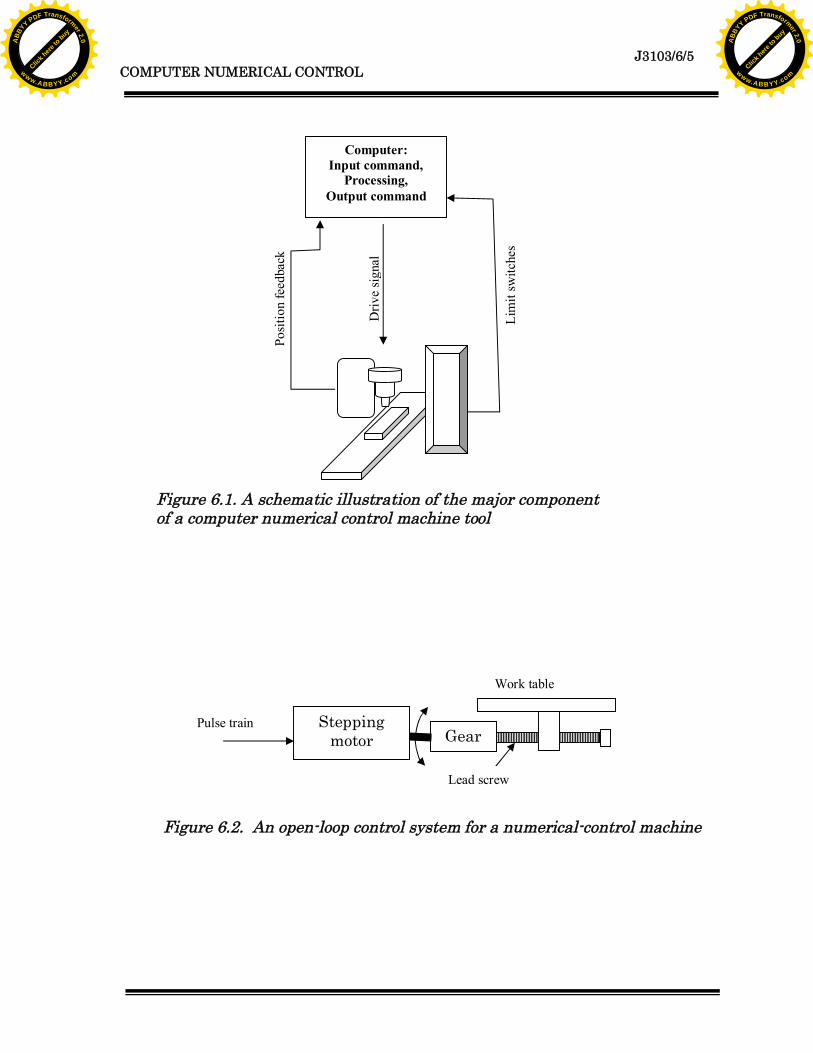
The interpretation of programme commands by a machine control unitand its conversion of those commands into machine motion is complex. Thebasic elements and operation of a typical NC machine are shown in Fig. 6.1. The
functional elements in numerical control and the components involved follow:a. Data input: The numerical information is read and stored in the
tape reader or in computer memoryb. Data processing: The programmes are read into the machine
control unit for processing.c. Data output: This is information is translated into commands
(typically pulsed commands) to the servomotor (Fig. 6.2 and 6.3).The servomotor then moves the table (on which the work piece ismounted) to specific positions, through linear or rotarymovements, by means of stepping motors, leadscrews, and othersimilar devices.
Click h
ere to
buy
ABB
YY PDF Transformer 2.0
www.ABBYY.comClic
k here
to buy
ABB
YY PDF Transformer 2.0
www.ABBYY.com
J3103/6/5COMPUTER NUMERICAL CONTROL
Computer:Input command,
Processing,Output command
Driv
e si
gnal
Posi
tion
feed
back
Lim
it sw
itche
sFigure 6.1. A schematic illustration of the major componentof a computer numerical control machine tool
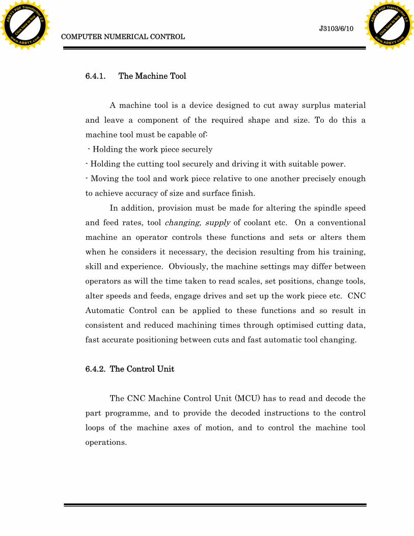
Steppingmotor Gear
Work table
Lead screw
Pulse train
Figure 6.2. An open-loop control system for a numerical-control machine
Click h
ere to
buy
ABB
YY PDF Transformer 2.0
www.ABBYY.comClic
k here
to buy
ABB
YY PDF Transformer 2.0
www.ABBYY.com

J3103/6/6COMPUTER NUMERICAL CONTROL
6.2. INDUSTRIAL APPLICATION
6.2.1. Metal MachiningLathes of all typesMilling Machines of all typesDrilling MachinesJig borers
Electric Discharge Machining (including wire cut machines)Laser cutting machinesMachining centresTurning centresAll types of grinding machinesGear cutting machines
6.2.2. Metal FormingPunching and nibblingGuillotinesFlame cut and profilingFolding
Comparator DAC
Lead screw Position sensor
Dcservomotor Gear
Work table
Feedback signal
Input
Figure 6.3. A closed-loop control system for a numerical-control machine
Click h
ere to
buy
ABB
YY PDF Transformer 2.0
www.ABBYY.comClic
k here
to buy
ABB
YY PDF Transformer 2.0
www.ABBYY.com

J3103/6/7COMPUTER NUMERICAL CONTROL
Pipe bendingMetal spinning
6.2.3. Finishing
PlatingPainting
6.2.4. Assembly Joining -Pick and place robots, spot and seam welding machines and robots,riveting, looming of wires and assembly of components into printed circuit
boards.
6.3. CNC AXIS CONVENTIONS
CNC axis classification follows the three-dimensional Cartesiancoordinate system and is established in BS 3635: 1972: Part 1. Fig. 5.3 shows the
tree primary axes and the associated rotational axes.Most machines have two or three slide ways placed at right angles to one
another. On CNC machines each slide is fitted with a control system, and isidentified with either the letter X, Y or Z.
Conventions have been adopted as to the naming of each axis. The axis ofthe main spindle, whether it is the axis of the tool spindle or the axis about
which the work piece rotates is called the Z axis.The X axis is the motion of the largest travel of the primary movement (in
case there is more than one).
Click h
ere to
buy
ABB
YY PDF Transformer 2.0
www.ABBYY.comClic
k here
to buy
ABB
YY PDF Transformer 2.0
www.ABBYY.com

J3103/6/8COMPUTER NUMERICAL CONTROL
The Y axis then makes the third motion and is the shorter primarymovement.
In addition to these primary linear axes, there is provision for Rotary
axes. They are designated A, B and C, with A rotary about the X axis, B rotaryabout the Y axis, and C rotary about the Z axis.
It is often required to command a motion parallel to X, Y or Z axes withinthe realm of a secondary motion, or a tertiary motion within special automaticcycles such as describing the amount of finish allowance on a turned part, or todescribe the distance of advancement of a drill during a drilling cycle etc. etc.
Linear Axes X Y Z
Rotary Axes A B C
Secondary Linear U V W
Interpolation I J K
Tertiary motion codes differ considerably, but the address charactersvariously used are P, Q, R, D, L, E, and H.
The z-axis is parallel to the main spindle of the machine. It will behorizontal on a lathe or horizontal machining centre and vertical on a verticalmachining centre.
The x-axis is always horizontal and at 90o to z.The y-axis is at right angles to both the x and z axes.
Table 6.1. NC axes
Click h
ere to
buy
ABB
YY PDF Transformer 2.0
www.ABBYY.comClic
k here
to buy
ABB
YY PDF Transformer 2.0
www.ABBYY.com

J3103/6/9COMPUTER NUMERICAL CONTROL
6.4. NC MACHINE SUB-UNIT
We have already seen the many and varied applications of numericalcontrol to the manufacturing and other industries, now we will look at themethods of controlling machines. There are three sub units to study:
The machine tool itself. The control unit.
The control system.
z
y
x
tablerotation
spindle
Figure 6.3. CNC axes
Click h
ere to
buy
ABB
YY PDF Transformer 2.0
www.ABBYY.comClic
k here
to buy
ABB
YY PDF Transformer 2.0
www.ABBYY.com
J3103/6/10COMPUTER NUMERICAL CONTROL
6.4.1. The Machine Tool
A machine tool is a device designed to cut away surplus material
and leave a component of the required shape and size. To do this amachine tool must be capable of: - Holding the work piece securely- Holding the cutting tool securely and driving it with suitable power.- Moving the tool and work piece relative to one another precisely enoughto achieve accuracy of size and surface finish.
In addition, provision must be made for altering the spindle speedand feed rates, tool changing, supply of coolant etc. On a conventionalmachine an operator controls these functions and sets or alters themwhen he considers it necessary, the decision resulting from his training,skill and experience. Obviously, the machine settings may differ betweenoperators as will the time taken to read scales, set positions, change tools,
alter speeds and feeds, engage drives and set up the work piece etc. CNCAutomatic Control can be applied to these functions and so result inconsistent and reduced machining times through optimised cutting data,fast accurate positioning between cuts and fast automatic tool changing.
6.4.2. The Control Unit
The CNC Machine Control Unit (MCU) has to read and decode thepart programme, and to provide the decoded instructions to the controlloops of the machine axes of motion, and to control the machine tooloperations.
Click h
ere to
buy
ABB
YY PDF Transformer 2.0
www.ABBYY.comClic
k here
to buy
ABB
YY PDF Transformer 2.0
www.ABBYY.com

J3103/6/11COMPUTER NUMERICAL CONTROL
The main grouping of parts of a control could be considered to be:The Control Panel.The Tape Reader,
The ProcessorsThe first part of the control panel is the human interface that
allows various modes of machine or control operation to be initiated, fromswitching on and homing, to programme loading and editing, to settingwork positions and tool offsets, manually controlled movements andcommencing the automatic cycling of a programme. Information about
machine status and condition is available to the operator via VDUscreens, gauges, meters, indicator lights and readouts.
The tape reader is the device used to transfer the programmeinformation contained on a programme tape into the control unit. Mosttape readers are of the photo-electric type which offers high speed readingwith reliability and accuracy providing the tape is in good condition and
the reader is kept clean and free of paper dust particles.The processors within a control are the electronic circuits that
permit conversion of part programme data into machine motions and theymay be classified into two main sections. The data processing unit andthe axis control processor. The function of the data processor is to decodethe commands of the part program, process it and provide data to the axis
control processor which then operates the slide drives and receivesfeedback signals on the actual position and velocity of each axis.
Click h
ere to
buy
ABB
YY PDF Transformer 2.0
www.ABBYY.comClic
k here
to buy
ABB
YY PDF Transformer 2.0
www.ABBYY.com
J3103/6/12COMPUTER NUMERICAL CONTROL
The Data Processing Unit includes the following functions:i. The input device, such a tape reader.ii. Reading circuits and parity checking logic.
iii. Decoding circuits for distributing data to the controlled axesiv. An interpolator to supply velocity commands to the axes, either
singly or in combination.The axis control processor consists of the following circuits:
i. Position control loops for each and all axes.ii. Velocity control loops.
iii. Deceleration and backlash take up circuits.
An MCU is adaptable to virtually any machine, the differing controlmotions and codes being a result of the way the control has beenprogrammed. This permanent resident program is known as an executiveprogramme and resides in the read only memory (ROM) of the control,
whereas the N.C. programme resides in the Random Access Memory(RAM). RAM allows external access and alteration if necessary, whileROM is programmed by the manufacturer and cannot be accessed throughthe control keyboard.
6.4.3. Control System
There are two types of control systems used on NC machines. Thepoint-to-point system and the continuous-path system. Point-to-pointsystems are not so common these days, but they operate only in straightlines, which are suitable for positioning moves on a drilling machine orlimited use on a lathe or milling machine, where at best 45% cuts are
possible with two axes running continuous path controls allow angular
Click h
ere to
buy
ABB
YY PDF Transformer 2.0
www.ABBYY.comClic
k here
to buy
ABB
YY PDF Transformer 2.0
www.ABBYY.com

J3103/6/13COMPUTER NUMERICAL CONTROL
path and radius motion because the control interpolator has the ability tomove the axis drive motors at varying velocities.
The point-to-point controls were NC controls, while the continuouspath controls could be NC or CNC controls.
NOTE: NC is a general term used for Numerical Control and is also a termused to describe controls that run directly off tape. CNC is aspecific term for Computer Numerical Control. CNC Machines areall NC machines, but NC controlled machines are not CNCmachines.
6.5. PROGRAM INPUT
Programmes can be produced and entered (loaded) by any of the followingmethods where available.
a. Punched Tape
b. Computerc. Direct Input
6.5.1. .Punched Tape
Punched tapes may be made of paper or plastic (Mylar) and have a
standard width of one inch (25.4mm) for the eight track (8 bit) formatused in numerical control.
A tape punch unit is connected to a teletype or similar keyboardand produces a punched tape during typing of the program. Alternatively,a punch unit can be connected to a personal computer (P.C.) and thecompleted programme punched. The holes punched in the tape form
Click h
ere to
buy
ABB
YY PDF Transformer 2.0
www.ABBYY.comClic
k here
to buy
ABB
YY PDF Transformer 2.0
www.ABBYY.com
J3103/6/14COMPUTER NUMERICAL CONTROL
certain patterns and the pattern represents a value when read by the tapereader on the MCU.
The pattern is a code in itself, and complies to a standard, eitherE.I.A. ( Electronics Industries Association ) which uses an odd number of
holes or I.S.O. ( International Standards Organization ) which uses aneven number of holes for each character. The I.S.O. code is mostcommonly used in Australia. The E.I.A. code is known as an odd paritysystem, and the I.S.O. code as an even parity system.
One of the tracks of each is assigned as a parity track and a hole issometimes punched there automatically to maintain the parity. The
purpose of parity is to check during tape reading for errors caused byunpunched holes, dirt or oil spots etc.
6.5.2. Computers
Personal computers can be used to type the programme in its
entirety while being visible on the screen, so mistakes can easily bespotted and corrected before the programme is loaded into the machine.
The programme can be down loaded to the machine via aconnecting link (interface cable) or via punched tape if a punch unit isconnected to a computer.
6.5.3. Direct Input
Programming at the machine may eliminate the need for tapepunching equipment and computers, but the machine is usually non-productive during this time.
Programming can be done by several methods, such as ;
Click h
ere to
buy
ABB
YY PDF Transformer 2.0
www.ABBYY.comClic
k here
to buy
ABB
YY PDF Transformer 2.0
www.ABBYY.com

J3103/6/15COMPUTER NUMERICAL CONTROL
- by typing the program directly into the memory of the M.C.U. throughthe edit function.
- programmes produced in this way can include all functions available, arestored in the machine ready for use at any time and can be output to a
punch unit or computer for external storage.
6.5.4. By Manual Data Input (M.D.I.)
M.D.I. may not allow all programming functions to operate, theprogramme can only be used once, and as it is not stored in the main
memory cannot be output to an external device. Additionally, somecontrols allow only one line (block) of programme to be entered andexecuted at a time.
6.5.5. Interactive Programming.
Some controls allow programming by a method that may besimpler and speedier than conventional N.C. program language. Thesemethods usually take up considerable memory space and so fewerprogrammes could be stored in the M.C.U. than if they were prepared byN.C. language. Most of the controls allowfor external storage of these programs providing the necessary devices are
at hand. Interactive programming can also be known as "conversational","symbolic", "blueprint","IGF" etc.
Click h
ere to
buy
ABB
YY PDF Transformer 2.0
www.ABBYY.comClic
k here
to buy
ABB
YY PDF Transformer 2.0
www.ABBYY.com

J3103/6/16COMPUTER NUMERICAL CONTROL
6.5.6. . External Devices.
A programme can be loaded directly from a P.C. as described, or from
other specialised units that have been designed as a portable device forloading, transferring or storing N.C. programs. The devices may store theinformation on floppy discs, hard discs, magnetic tape, or through solidstate circuitry. Those with discs or magnetic tape would be no larger thana briefcase or perhaps a tissue box, down to pocket calculator size for solidstate devices.
NOTE: Where punched tape was once the only practical way for mostprogrammers to transfer (or load) their programs into the controls, it ispresently being overtaken by personal computers connected directly viainterface cable. Other popular and convenient methods are simplythrough the edit mode or by interactive (conversational) programming.
Companies specialising in complex die work probably use DNC more oftennow. Inputting through M.D.I. mode is common providing the restrictionsnoted are adhered to.
6.6. NC PROGRAMMING
6.6.1. Job Planning1. Sketch the part. Add incremental or absolute dimensions.2. Ascertain fixturing. Select fixtures which have minimal projections
above the part.3. Identify a set-up point. Locate the set-up point near:
1. A corner of the part
2. A spot above the fixture
Click h
ere to
buy
ABB
YY PDF Transformer 2.0
www.ABBYY.comClic
k here
to buy
ABB
YY PDF Transformer 2.0
www.ABBYY.com

J3103/6/17COMPUTER NUMERICAL CONTROL
Consider space requirements for:1. Part loading and unloading2. Tool change.
4. Plan operation sequence Mark sequence pattern of sketch.Test program data for accuracy.
5. Record necessary data foreach movement of the tableand tool on the programsheet.
6. Record instructions for Identify, specific:the machine operator. 1. Tools needed.
2. Speed and feed data3. Tool change points4. Console switch setting
6.6.2. Incremental
The word "incremental" may be defined as a dimension or amovement with respect to the preceding point in a prescribed sequence ofpoints. Each positioning move is described quantitatively in distance andin direction from a previous point rather than from a fixed zero reference
point.
Click h
ere to
buy
ABB
YY PDF Transformer 2.0
www.ABBYY.comClic
k here
to buy
ABB
YY PDF Transformer 2.0
www.ABBYY.com
J3103/6/18COMPUTER NUMERICAL CONTROL
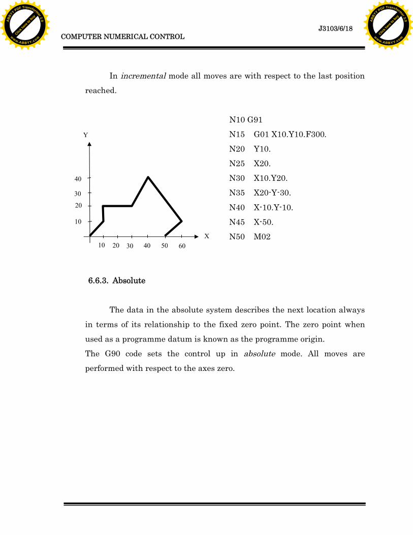
In incremental mode all moves are with respect to the last positionreached.
N10 G91N15 G01 X10.Y10.F300.N20 Y10.N25 X20.N30 X10.Y20.N35 X20-Y-30.
N40 X-10.Y-10.N45 X-50.N50 M02
6.6.3. Absolute
The data in the absolute system describes the next location alwaysin terms of its relationship to the fixed zero point. The zero point whenused as a programme datum is known as the programme origin.The G90 code sets the control up in absolute mode. All moves areperformed with respect to the axes zero.
40
30
20
10 20 30 40 50 60
10
Y
X
Click h
ere to
buy
ABB
YY PDF Transformer 2.0
www.ABBYY.comClic
k here
to buy
ABB
YY PDF Transformer 2.0
www.ABBYY.com

J3103/6/19COMPUTER NUMERICAL CONTROL
N10 G90N15 G01X10.Y10.F300.N20 Y20.N25 X30.
N30 X40.Y40.N35 X60.Y10.N40 X50.Y0.N45 X0.N50 M02
6.6.4. Linear Interpolation
Under this command the machine tool will move in a straight lineat a defined feed rate. Combined axis motions (angled moves) will be
executed at the programming feed rate as the control will reduce thevelocity of both axes accordingly.
E.g. G01 X200. F250.G01 Move in a straight lineX200. A distance of 20O.mm
F250. At a feed rate of 250.mm/min.
NOTE: If a new line with G01 is listed again somewhere below, the F250 doesnot have to be written again. This is called modal.
40
30
20
10 20 30 40 50 60
10
Y
Click h
ere to
buy
ABB
YY PDF Transformer 2.0
www.ABBYY.comClic
k here
to buy
ABB
YY PDF Transformer 2.0
www.ABBYY.com
J3103/6/20COMPUTER NUMERICAL CONTROL
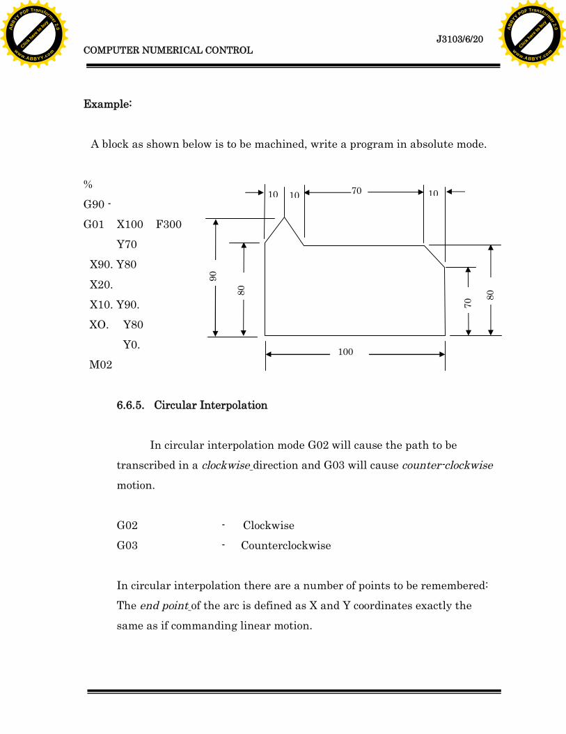
Example:
A block as shown below is to be machined, write a program in absolute mode.
%G90 -G01 X100 F300
Y70X90. Y80
X20.X10. Y90.XO. Y80
Y0.M02
6.6.5. Circular Interpolation
In circular interpolation mode G02 will cause the path to betranscribed in a clockwise direction and G03 will cause counter-clockwisemotion.
G02 - ClockwiseG03 - Counterclockwise
In circular interpolation there are a number of points to be remembered:The end point of the arc is defined as X and Y coordinates exactly thesame as if commanding linear motion.
100
70
70
80
90
101010
80
Click h
ere to
buy
ABB
YY PDF Transformer 2.0
www.ABBYY.comClic
k here
to buy
ABB
YY PDF Transformer 2.0
www.ABBYY.com

J3103/6/21COMPUTER NUMERICAL CONTROL
The centre of the arc is defined with respect to the start point in the I andJ words as an "increment" from this point.For G02 and G03 to function the feed rate "F." must be specified.
Example:
N5% N10 G90N15 G01 Y110. F200.
N20 G02 X20. I10.N25 G03 X30. Y100. I10.N30 G01 X90.N35 G02 X100. Y90. J-10.N40 G01 Y10,N45 G02 X90. Y0. I-10.
N50 G01 X0.N55 M02
6.7. PROGRAM DEFINITION
To enable the machine to operate automatically it is necessary to put into
its memory a programme or set of instructions to carry out the requiredoperation.
a) Programme.A programme is a series of instructions to the machine, set out in
sequence to -produce a complete machining operation. A programme ismade up of a series of blocks.
100
110
All radius – R10
Click h
ere to
buy
ABB
YY PDF Transformer 2.0
www.ABBYY.comClic
k here
to buy
ABB
YY PDF Transformer 2.0
www.ABBYY.com

J3103/6/22COMPUTER NUMERICAL CONTROL
b) Block.-A block or programme line is a set of instructions to the machine
that are carried out simultaneously. A block is made up of one or more
Words and is terminated by an End of Block which is the Line FeedCharacter.
c) Word.A word is a specific instruction to the machine that will affect a
particular machine function. Every word consists of a Letter Code and a
Numerical value.
Examples of Dimensional Words: X100. Y2.345 F0.25Examples of Non-Dimensional Words: N25 G90 M03 S1200
Dimension words can be written in various ways, depending on the
control. Let's take the examples X100. Y2.345 some older controls cannot acceptdecimal points, so both dimensional words would be written X100000 Y2345,with Y showing all decimal places. With these controls, if the X word was writtenas X100, it would be interpreted as one-tenth of a millimeter, not one hundredmillimeters.
If a control accepts decimal points, then ALL dimensional words should
have a decimal point. On any control, non-dimensional must NOT have adecimal point. The method of writing words beginning with a letter is known asword address format and is now almost universally used.
Click h
ere to
buy
ABB
YY PDF Transformer 2.0
www.ABBYY.comClic
k here
to buy
ABB
YY PDF Transformer 2.0
www.ABBYY.com

J3103/6/23COMPUTER NUMERICAL CONTROL
6.7.1. Program
(Start of Program)
(Material 25.mm. dia.)(Grip 120.m.m. from Front of Jaws)N01 G71G90G95N02 G50X100.Z130.N03 S2000M03
(Select Turning & Facing Tool)N05 GO1X2.F.O4N06 GOOZ120.N07 X24.N08 G01Z20.
N09 X26.N10 G00X100.Z130.T0100N11 M02
WORD ADDRESS The letter at the beginning of each word is called theaddress character.
e.g. X Y Z for Axis designating wordF for Feed ratesG for Preparatory functionsM for miscellaneous functionN for Sequence numbers
N04 G00X26.Z119.T0101 BLOCK
WORDSN10 GOOX100. Z130. T0100
Click h
ere to
buy
ABB
YY PDF Transformer 2.0
www.ABBYY.comClic
k here
to buy
ABB
YY PDF Transformer 2.0
www.ABBYY.com

J3103/6/24COMPUTER NUMERICAL CONTROL
CNC mills, drills and machining centers are all equipped with cycles toperform drilling, reaming, counter boring, boring and tapping operations. Someothers have pocketing cycles, slot cutting cycles, hole pattern cycles etc, all of
which are designed to save programming time and effort.CNC lathes usually have cycles to cover drilling, grooving/parting, screw
cutting, repetitive cut (automatic roughing) operations and others. Each cyclehas its own G code to control the sequence of motions and an accompanying setof words to define the parameters of those motions. These words have addressessuch as: R,P,Q,D,E,I,K,H,B etc.
6.7.2. Program Preparation
CNC programmes can be prepared manually, where the programmerusually roughs the programme out on paper, then produces it via a keyboarddevice of the type detailed below, or by assisted preparation in which a computer
plays a predominant role -such as when CAD/CAM packages have been installedfor design and programming.
The programmer must posses knowledge and skills in planning machiningsequences, fixturing, cutting data, cutting tools, calculations, as well as beingfamiliar with the machines he is programming. To implement these skills to besteffect a programmer should be prepared to observe critically his programs in use
and modify them as necessary in order to gain maximum machine utilization.
6.7.3. Operation of program
Before a machine can set into automatic motion a program must bechecked for errors. A simple typing mistake - an incorrect code, a minus sign
instead of a zero, the exclusion of a decimal etc, could cause and expensive
Click h
ere to
buy
ABB
YY PDF Transformer 2.0
www.ABBYY.comClic
k here
to buy
ABB
YY PDF Transformer 2.0
www.ABBYY.com

J3103/6/25COMPUTER NUMERICAL CONTROL
machine crash. Anyone who considers their programmes to be without error andnot in need of careful and conscientious trialing has an attitude problem and isplacing expensive machinery and operators safety at risk.
There may be many ways in which a programme can be checked forerrors, but a programme can only be proved 100% by running the machine andproducing a part.
Error checking can be performed in a variety of ways:Verification: Read through the print-out (NOT the handwritten
manuscript) carefully - sometimes mistakes can be seen
easily.Trialing: This involves the execution of the programme without
actually cutting the part and may be carried out in severalways depending on the type of machine, or control, or eventhe philosophy of the person in charge. Adhere to the later unlessyou can put up good reasons for alteration.
Trialing usually consists of running the machinewith the singleblock switch active, that is, each block will only be executed bypressing cycle start, in conjunction with the programmebeing displayed on the screen.Quite often the dry run mode is switched on to hastenProceedings. 'Dry Run' results in all machine motion being
executed at a preset rate, usually in the region of 50% to 80%of the rapid traverse capability of the machine. The actual axisvelocity can be overridden from 0% to 100%. Thedisadvantage of dry running a programme is that feed rates willbe masked, and attention must be paid to determining theactual programmed feed rate for each block. This may be
displayed on the screen.
Click h
ere to
buy
ABB
YY PDF Transformer 2.0
www.ABBYY.comClic
k here
to buy
ABB
YY PDF Transformer 2.0
www.ABBYY.com

J3103/6/26COMPUTER NUMERICAL CONTROL
Every movement the machine makes during programmetrialing should be expected and accountable to theprogrammer, if not, those motions should be checked for
viability, and if necessary, a more thorough understanding ofthe machine operation should be sought.
Editing: Wherever errors are found, they should be corrected andrechecked, be it on the machine or at the programmingstation. Whenever a programme is edited on the machine, a
note should be made on the print-out so the master ororiginal programme can also be corrected. A better method isto punch out a programme from the control after successfullyproducing a component.
6.8. TYPES OF CONTROL SYSTEM
There are two basic types of control systems in numerical control: point-to-point and contouring.
a. In a point-to-point system, also called positioning, each axis of themachine is driven separately by lead screws and, depending on thetype of operation, at different velocities. The machine moves initially
at maximum velocity in order to reduce non-productive time, butdecelerates as the tool approaches its numerically defined position.Thus, in an operation such as drilling (or punching a hole), thepositioning and cutting take place sequentially (Fig. 5.4).
Click h
ere to
buy
ABB
YY PDF Transformer 2.0
www.ABBYY.comClic
k here
to buy
ABB
YY PDF Transformer 2.0
www.ABBYY.com

J3103/6/27COMPUTER NUMERICAL CONTROL
After the hole is drilled or punched, the tool retracts upward andmoves rapidly to another position, and the operation is repeated. Thepath followed from one position to another is important in only onerespect. It must be chosen to minimize the time of travel, for better
efficiency. Point-to-point systems are used mainly in drilling,punching, and straight milling operations.
Position Coordinate(X)
Coordinate(Y)
C.P. -15 15
Point 1 10 -10
Point 2 55 -10
Point 3 55 -55
Point 4 10 -55
Position Coordinate(X)
Coordinate(Y)
C.P. -15 15
Point 1 25 -25
Point 2 45 0
Point 3 0 -45
Point 4 -45 0
Incremental (G90) Absolute (G91)
Figure 5.4. Point-to point system
C.P15
15
(0,0)
10
10 45
45
1 2
34
Click h
ere to
buy
ABB
YY PDF Transformer 2.0
www.ABBYY.comClic
k here
to buy
ABB
YY PDF Transformer 2.0
www.ABBYY.com
J3103/6/28COMPUTER NUMERICAL CONTROL
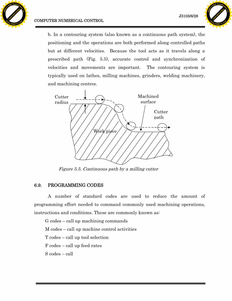
b. In a contouring system (also known as a continuous path system), thepositioning and the operations are both performed along controlled pathsbut at different velocities. Because the tool acts as it travels along aprescribed path (Fig. 5.5), accurate control and synchronization of
velocities and movements are important. The contouring system istypically used on lathes, milling machines, grinders, welding machinery,and machining centres.
6.9. PROGRAMMING CODES
A number of standard codes are used to reduce the amount ofprogramming effort needed to command commonly used machining operations,instructions and conditions. These are commonly known as:
G codes – call up machining commandsM codes – call up machine control activitiesT codes – call up tool selectionF codes – call up feed ratesS codes – call
Figure 5.5. Continuous path by a milling cutter
Cutterradius
Cutterpath
Machinedsurface
Work piece
Click h
ere to
buy
ABB
YY PDF Transformer 2.0
www.ABBYY.comClic
k here
to buy
ABB
YY PDF Transformer 2.0
www.ABBYY.com
J3103/6/29COMPUTER NUMERICAL CONTROL
- modal codes remain active after being entered, unless they are cancelledby another G code; and- non-modal codes are only active in the programme block in which they
appear.
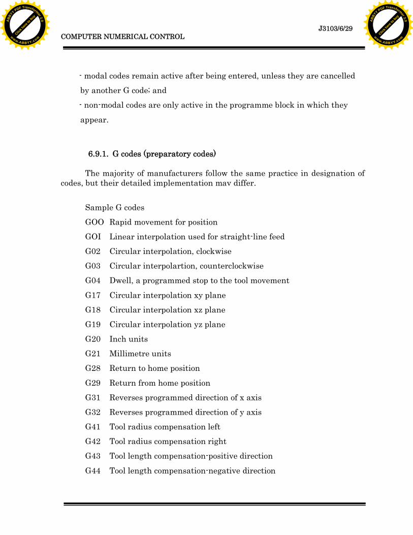
6.9.1. G codes (preparatory codes)
The majority of manufacturers follow the same practice in designation ofcodes, but their detailed implementation mav differ.
Sample G codesGOO Rapid movement for positionGOI Linear interpolation used for straight-line feedG02 Circular interpolation, clockwiseG03 Circular interpolartion, counterclockwiseG04 Dwell, a programmed stop to the tool movement
G17 Circular interpolation xy planeG18 Circular interpolation xz planeG19 Circular interpolation yz planeG20 Inch unitsG21 Millimetre unitsG28 Return to home position
G29 Return from home positionG31 Reverses programmed direction of x axisG32 Reverses programmed direction of y axisG41 Tool radius compensation leftG42 Tool radius compensation rightG43 Tool length compensation-positive direction
G44 Tool length compensation-negative direction
Click h
ere to
buy
ABB
YY PDF Transformer 2.0
www.ABBYY.comClic
k here
to buy
ABB
YY PDF Transformer 2.0
www.ABBYY.com

J3103/6/30COMPUTER NUMERICAL CONTROL
G70 Imperial unitG71 Metric unitsG80 Cancel canned cycle
G81 Drilling cycleG82 Drilling cycle with dwellG83 Deep hole drillingG84 Tapping cycleG85 89-boring cyclesG90 Absolute mode
G91 Incremental mode
6.9.2. M codes
These control the auxiliary functions of the machine.MOO Program stop
M02 End of programM03 Spindle on, clockwiseM04 Spindle on, counter clockwiseM05 Spindle offM06 Tool changeM07 Oil mist coolant on
M08 Flood coolant onM09 Coolant offM30 End of tape
Click h
ere to
buy
ABB
YY PDF Transformer 2.0
www.ABBYY.comClic
k here
to buy
ABB
YY PDF Transformer 2.0
www.ABBYY.com

J3103/6/31COMPUTER NUMERICAL CONTROL
6.10. WRITING A PROGRAM
Position Coordinate (X) Coordinate (Y)
C.P. 0 0
P. 1 45.0 -25.0
P. 2 70.0 -25.0
P. 3 60.0 -65.0
P. 4 45.0 -50.0
P. 5 60.0 -50.0
P. 6 49.393 -75.607
P. 7 38.787 -65.0
P. 8 15.0 -65.0
Figure 5.6. To cut a ‘S’-slot/groove with a point-to-pointmethod and a continuous path/contouring system
Table 5. Reference points and X and Y coordinates to cut a ‘S’-slot/groovewith a point-to-point method and a continuous path/contouring system
Click h
ere to
buy
ABB
YY PDF Transformer 2.0
www.ABBYY.comClic
k here
to buy
ABB
YY PDF Transformer 2.0
www.ABBYY.com
J3103/6/32COMPUTER NUMERICAL CONTROL
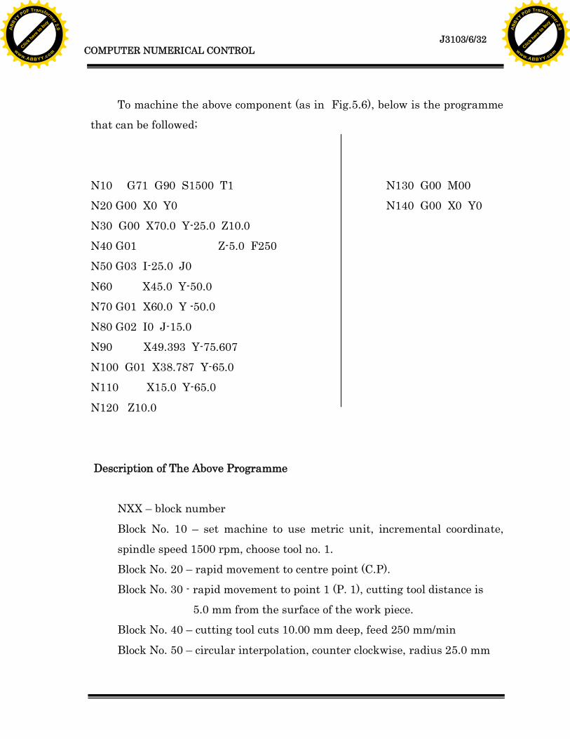
To machine the above component (as in Fig.5.6), below is the programmethat can be followed;
N10 G71 G90 S1500 T1 N130 G00 M00N20 G00 X0 Y0 N140 G00 X0 Y0N30 G00 X70.0 Y-25.0 Z10.0N40 G01 Z-5.0 F250N50 G03 I-25.0 J0
N60 X45.0 Y-50.0N70 G01 X60.0 Y -50.0N80 G02 I0 J-15.0N90 X49.393 Y-75.607N100 G01 X38.787 Y-65.0N110 X15.0 Y-65.0
N120 Z10.0
Description of The Above Programme
NXX – block number
Block No. 10 – set machine to use metric unit, incremental coordinate,spindle speed 1500 rpm, choose tool no. 1.Block No. 20 – rapid movement to centre point (C.P).Block No. 30 - rapid movement to point 1 (P. 1), cutting tool distance is
5.0 mm from the surface of the work piece.Block No. 40 – cutting tool cuts 10.00 mm deep, feed 250 mm/min
Block No. 50 – circular interpolation, counter clockwise, radius 25.0 mm
Click h
ere to
buy
ABB
YY PDF Transformer 2.0
www.ABBYY.comClic
k here
to buy
ABB
YY PDF Transformer 2.0
www.ABBYY.com

J3103/6/33COMPUTER NUMERICAL CONTROL
Block No. 60 – tool ends interpolation cutting at P. 4Block No. 70 – linear interpolation until P. 5Block No. 80 - circular interpolation, clockwise, radius 15.0 mm
Block No. 90 - tool ends interpolation cutting at P. 6Block No. 100 - linear interpolation until P. 7Block No. 110 - linear interpolation until P. 8Block No. 120 – tool rises up 10.0 mmBlock No. 130 – program stopsBlock No. 140 - rapid return to centre point (C.P).
6.11. ADVANTAGES OF COMPUTER NUMERICAL CONTROL
i. The component programming tape and the tape reader are usedonce only when the programme is copied into the computermemory, not only this practice wills same time but it will also
reduce errors.ii. The programming tape can be edited on the shop floor, when the
machine is placed/located. Editing, correction and optimising; suchas machine tool operations, spindle speeds and speeds; are usuallydone in the test run of the tape.
iii. Computer numerical control can easily changes into metric system
if the programme is in the imperial units.iv. It is widely used in industry. It is easily adaptable in a
computerised industry system.v. Increased flexibility – the machine can produce a specific part,
followed by other parts with different shapes, and at reduces cost.vi. Greater accuracy – computers have a higher sampling rate and
faster operation.
Click h
ere to
buy
ABB
YY PDF Transformer 2.0
www.ABBYY.comClic
k here
to buy
ABB
YY PDF Transformer 2.0
www.ABBYY.com

J3103/6/34COMPUTER NUMERICAL CONTROL
vii. More versatility – editing and debugging programmes,reprogramming, and plotting and printing part shape are simpler.
viii. Programmes are stored on the machine ready for use.
ix. Programmes and data can be modified on the machine.
Click h
ere to
buy
ABB
YY PDF Transformer 2.0
www.ABBYY.comClic
k here
to buy
ABB
YY PDF Transformer 2.0
www.ABBYY.com
J3103/6/35COMPUTER NUMERICAL CONTROL
6.1. Briefly state four (4) advantages of numerical control system.
6.2. You are given a drawing of a component. List down the steps you would take tooperate a NC machine in order produce the component.
6.3. Write a short paragraph on three (3) basic components of a numerical control system.
ACTIVITY 6
Click h
ere to
buy
ABB
YY PDF Transformer 2.0
www.ABBYY.comClic
k here
to buy
ABB
YY PDF Transformer 2.0
www.ABBYY.com

J3103/6/36COMPUTER NUMERICAL CONTROL
6.1. The advantages of numerical control system are:i. The component programming tape and the tape reader are used
once only when the programme is copied into the computermemory, not only this practice wills same time but it will alsoreduce errors.
ii. The programming tape can be edited on the shop floor, when themachine is placed/located. Editing, correction and optimising; suchas machine tool operations, spindle speeds and speeds; are usuallydone in the test run of the tape.
iii. Computer numerical control can easily changes into metric systemif the program is in the imperial units.
iv. It is widely used in industry. It is easily adaptable in acomputerised industry system.
v. Increased flexibility – the machine can produce a specific part,followed by other parts with different shapes, and at reduces cost.
vi. Greater accuracy – computers have a higher sampling rate andfaster operation.
vii. More versatility – editing and debugging programs,reprogramming, and plotting and printing part shape are simpler.
viii. Programs are stored on the machine ready for use.ix. Programs and data can be modified on the machine.
FEEDBACK ON ACTIVITY 6
Click h
ere to
buy
ABB
YY PDF Transformer 2.0
www.ABBYY.comClic
k here
to buy
ABB
YY PDF Transformer 2.0
www.ABBYY.com

J3103/6/37COMPUTER NUMERICAL CONTROL
6.2. Job Planning
1. Sketch the part. Add incremental or absolute dimensions.2. Ascertain fixturing. Select fixtures which have minimal projections
above the part.3. Identify a set-up point. Locate the set-up point near:
1. A corner of the part2. A spot above the fixture
Consider space requirements for:1. Part loading and unloading
2. Tool change.4. Plan operation sequence Mark sequence pattern of sketch.
Test program data for accuracy.5. Record necessary data for
each movement of the tableand tool on the program
sheet.6. Record instructions for Identify, specific:
the machine operator. 1. Tools needed.2. Speed and feed data3. Tool change points4. Console switch setting
6.3.(a) Machine Tool - a device designed to cut away surplus material and leave
a component of the required shape and size. It holds the work piece, cutting tooland moves the tool and work piece relative to one another precisely enough toachieve accuracy of size and surface finish. It can also alter the spindle speedand feed rates, tool changing, supply of coolant etc.
Click h
ere to
buy
ABB
YY PDF Transformer 2.0
www.ABBYY.comClic
k here
to buy
ABB
YY PDF Transformer 2.0
www.ABBYY.com

J3103/6/38COMPUTER NUMERICAL CONTROL
(b) The Control Unit - reads, decodes the part programme and provides the
decoded instructions to the control loops of the machine axes of motion,and to control the machine tool operations. There are three main parts of
the control unit namely, the Control Panel, the Tape Reader and theProcessors
(c) Control system - there are two types of control systems used on NC
machines - the point-to-point system and the continuous-path system.The point-to-point systems operates only in straight lines, which aresuitable for positioning moves on a drilling machine or limited use on alathe or milling machine, where at best 45% cuts are possible with two
axes running continuous path controls allow angular path and radiusmotion because the control interpolator has the ability to move the axisdrive motors at varying velocities. The point-to-point controls were NCcontrols, while the continuous path controls could be NC or CNC controls.
Click h
ere to
buy
ABB
YY PDF Transformer 2.0
www.ABBYY.comClic
k here
to buy
ABB
YY PDF Transformer 2.0
www.ABBYY.com

J3103/6/39COMPUTER NUMERICAL CONTROL
1. Numerical control machine can be done in absolute coordinate (G90) and incrementalcoordinates (G91). What is the difference between the two coordinates.
2. By using G90 and G 91 coordinates write a program to cut a component in is the .belowfigure.
SELF-ASSESSMENT 6
30
70
J20
20
60
35
Click h
ere to
buy
ABB
YY PDF Transformer 2.0
www.ABBYY.comClic
k here
to buy
ABB
YY PDF Transformer 2.0
www.ABBYY.com
J3103/6/40COMPUTER NUMERICAL CONTROL
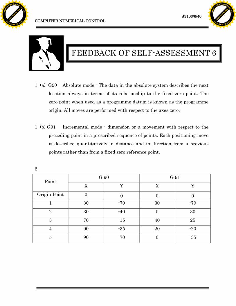
1. (a) G90 Absolute mode - The data in the absolute system describes the nextlocation always in terms of its relationship to the fixed zero point. Thezero point when used as a programme datum is known as the programmeorigin. All moves are performed with respect to the axes zero.
1. (b) G91 Incremental mode - dimension or a movement with respect to thepreceding point in a prescribed sequence of points. Each positioning moveis described quantitatively in distance and in direction from a previouspoints rather than from a fixed zero reference point.
2.
G 90 G 91Point
X Y X Y
Origin Point 0 0 0 01 30 -70 30 -70
2 30 -40 0 30
3 70 -15 40 25
4 90 -35 20 -20
5 90 -70 0 -35
FEEDBACK OF SELF-ASSESSMENT 6
Click h
ere to
buy
ABB
YY PDF Transformer 2.0
www.ABBYY.comClic
k here
to buy
ABB
YY PDF Transformer 2.0
www.ABBYY.com

Click h
ere to
buy
ABB
YY PDF Transformer 2.0
www.ABBYY.comClic
k here
to buy
ABB
YY PDF Transformer 2.0
www.ABBYY.com