unit v part programming
TRANSCRIPT

UNIT – V
PART PROGRAMMING
SPRX1008 – PRODUCTION TECHNOLOGY - II
Methods of NC Part Programming
The tape can be prepared for submission to the MCU using any of several different methods of
NC part programming. NC programming represents one of the elements in the broader procedure
called process planning. We defined process planning as a function of manufacturing
engineering in which the sequence of individual production operations for making the part are
planned. We assume here that a portion of the processing is to be done on one or more NC
machines. For those machines, the program must be prepared.
The part programming methods include a variety of procedures ranging from highly manual to
highly automated:
1. Manual part programming
2. Computer assisted part programming
3. Manual data input
4. NC programming using CAD/CAM
5. Computer automated part programming
In manual part programming, the processing instructions are documented on a form called a part
program manuscript. The manuscript is a listing of the positions of the tool relative to the work
piece that the machine must follow in order to perform the processing. The listing may also
include other commands such as speeds, feeds, tooling, and so on. A punched tape is then
prepared directly from the manuscript.
In computer-assisted part programming, much of the tedious computational work required in
manual programming is performed by the computer. For complex work part geometries or jobs
with many processing steps, use of the computer results in significant savings in the part
programmer’s time. When computer assisted part programming is used, the programmer
prepares the set of processing instructions in a high-level computer language. For complex jobs,
this computer language is much easier to use than the lower-level coding required in manual part
programming. The high-level language commands are interpreted by the computer, and the
required calculations and data processing are accomplished to prepare the NC program for the
tape reader (or other input device).
Manual data input (MDI) is a procedure in which the NC program is entered directly into the
MCU at the site of the processing machine. Consequently, the use of the punched tape is
avoided, and the programming procedure is simplified to permit machine operators rather than
part programmers to do the programming.
NC part programming using CAD/CAM is an advanced form of computer-assisted part
programming in which an interactive graphics system equipped with NC programming software
is used to facilitate the part programming task. The term CAD/CAM means computer-aided
design and computer-aided manufacturing. In this method the programmer works on a
CAD/CAM workstation to enter the machining commands. The actions indicated by the
commands are displayed on the graphics monitor, which provides visual feedback to the
programmer. Also, certain portions of the programming cycle are automated by the NC
programming software to reduce the total programming time required.
Computer-automated part programming extends the notion of automating certain portions of the.
NC part programming procedure to its logical conclusion. It automates the complete part
programming task using software that is capable of making logical and even quasi intelligent
decisions about how the part should be machined.
Manual Part Programming
In manual programming, the part programmer specifies the machining instructions on a form
called a manuscript. Manuscripts come in various forms, depending on the machine tool and tape
format to be used. For example, the manuscript form for a two-axis point-to-point drilling
machine would be different than one for a three-axis contouring machine.
As mentioned, the manuscript is a listing of the relative tool and workpiece locations. It also
includes other data, such as preparatory commands, miscellaneous instructions, and speed/feed
specifications, all of which are needed to operate the machine under tape control. The manuscript
is designed so that the NC tape can be typed directly from it on a Flexowriter or similar tape-
punch device.
We shall divide manual programming jobs into two categories : point-to-point jobs and
contouring jobs. Except for complex work parts with many holes to be drilled, manual
programming is ideally suited for point-to-point applications. On the other hand, except for the
simplest milling and turning jobs, manual programming can become quite time-consuming for
applications requiring continuous-path control of the tool. Accordingly, we shall only concern
ourselves with manual part programming for point-to-point operations in this chapter. Manual
contour programming requires such tedious and detailed calculations that the space needed for
the topic would be more than is warranted by the basic purpose of this book, which is to survey
the field of automated manufacturing systems.

COMPUTER ASSISTED PART PROGRAMMING
Computer Assisted Part Programming was relatively simple, it was a suitable application for
manual programming. Most parts machined on NC systems are considerably more complex. In
the more complicated point-to-point jobs and in contouring applications, manual part
programming becomes an extremely tedious task and subject to error. In these instances it is
much more appropriate to employ the high-speed digital computer to assist in the part
programming process. Many part programming language systems have been developed to
automatically perform most of the calculations which the programmer would otherwise be forced
to do. This saves time and results in a more accurate and more efficient part program.
The part programmer’s job
The difference in the part programmer’s job between manual programming and computer-
assisted programming is this. With manual programming, a manuscript is used which is
formatted so that the NC tape can be typed directly from it. With computer-assisted part
programming, the machining instructions are written in English-like statements of the NC
programming language, which are then processed by the computer to prepare the tape. The
computer automatically punches the tape in the proper tape format for the particular NC
machine.
When utilizing one of the NC programming languages, part programming can be summarized as
consisting basically of two tasks :
1. Defining the geometry of the work part
2. Specifying the tool path and/or operation sequence
Let us now consider these two tasks in computer-assisted part programming. Our frame of
reference will be for a contouring application, but the concepts apply for a positioning
application as well.
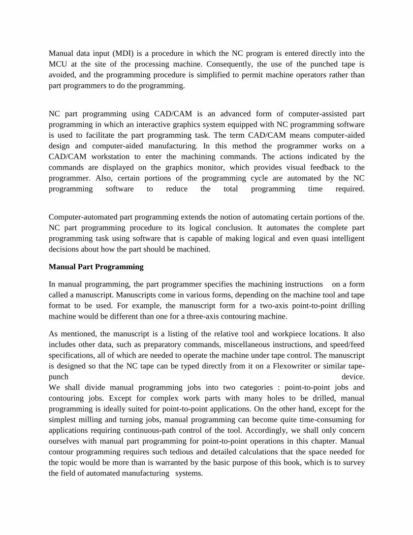
Fig: 1 Basic Geomentry Element
WORK PART GEOMETRY DEFINITION:
No matter how complicated the work part may appear, it is composed of basic geometric
elements. Using a relatively simple work part to illustrate, consider the component shown in
Figure 1. Although somewhat irregular in overall appearance, the outline of the part consists of
intersecting straight lines and a partial circle. The holes in the part can be expressed in terms of
the center location and radius of the hole. Nearly any component that can be conceived by a
designer can be described by points, straight lines, planes, circles, cylinders, and other
mathematically defined surfaces. It is the part programmer’s task to enumerate the component
elements out of which the work part is formed. Each geometric element must be identified and
the dimensions and location of the element explicitly defined. Using the APT programming
language as an example, the following statement might be used to define a point :
P1 – POINT/6.0, 1.125,0
The point is identified by the symbol P1 and is located at x = 6.0, y = 1.125, and z = 0.
Similarly, a circle in the x–y plane might be defined by the APT statement
C1 = CIRCLE/CENTER, P1 , RADIUS, 1.12
The center of circle C1 is Pi (previously defined) and the radius is 1.125.
The various geometric elements in the drawing of Figure 9.7 would be identified in a similar
fashion by the part programmer.
TOOL PATH CONSTRUCTION
After defining the work part geometry, the programmer must next construct the path that the
cutter will follow to machine the part. This tool path specification involves a detailed step-by-
step sequence of cutter moves. The moves are made along the geometry elements which have
previously been defined. To illustrate, using Figure 1 and the APT language, the following
statement could be used to command the tool to make a left turn from line L2 onto line L3 :
GOLFT/L3, PAST, L1
This assumes the tool was previously located at the intersection of lines L2 and L3 and had just
finished a cut along L2. The statement directs the tool to cut along L3 until it just passes line L1.
By using statements similar to the above, the tool can be directed to machine along the work part
surfaces, to go to point locations, to drill holes at those point locations, and so on. In addition to
geometry definition and tool path specification, the part programmer also provides other
commands to the NC system. However, let us await Section 9.5, where we will consider a wide
range of possible APT statements.

The computer’s job
The computer’s job in computer-assisted part programming consists of the following steps:
1. Input translation
2. Arithmetic calculations
3. Cutter offset computation
4. Post processor
The sequence of these steps and their relationships to the part programmer and the machine tool
are illustrated in Figure 2
Fig.2 Steps in Computer Assisted Part Programming
INPUT TRANSLATION: The part programmer enters the program using the APT or other
language. The input translation component converts the coded instructions contained in the
program into computer-usable form, preparatory to further processing.
ARITHMETIC CALCULATIONS: The arithmetic calculations unit of the system consists of
a comprehensive set of subroutines for solving the mathematics required to generate the part
surface. These subroutines are called by the various part programming language statements. The
arithmetic unit is really the fundamental element in the part programming package. This unit
frees the programmer from the time-consuming geometry and trigonometry calculations to
concentrate on the work part processing.
CUTTER OFFSET COMPUTATION: When we described the second task of the part
programmer as that of constructing the tool path, we ignored one basic factor the size of the
cutting tool. The actual tool path is different from the part outline. I is is because the tool path is
the path taken by the center of the cutter. It is at the periphery of the cutter that machining takes
place.

The purpose of the cutter offset computation is to offset the tool path from the desired part
surface by the radius of the cutter. This means that the part programmer can define the exact part
outline in his geometry statements. Thanks to the cutter offset calculation provided by the
programming system, he need not concern himself with this task. The cutter offset problem is
illustrated in Figure 3
POST PROCESSOR. As we have noted previously, NC machine tool systems are different.
They have different features and capabilities. They use different NC tape formats. Nearly all of
the part programming languages, including APT, are designed to be general-purpose languages,
not limited to one or two machine tool types. Therefore, the final task of the computer in
computer-assisted part programming is to take the general instructions and make them specific to
a particular machine tool system. The unit that performs this task is called a post processor.
The post processor is really a separate computer program that has been written to prepare the
punched tape for a specific machine tool. The input to the post processor is the output from the
other three components: a series of cutter locations and other instructions. This is referred to as
the CLFILE or CLDATA (CL stands for cutter location). The output of the post processor is the
NC tape written in the correct format for the machine on which it is to be used.
Fig.3 Cutter Offset Problem in computer-assisted part programming
Structure of Part Program
A part program is simply an NC program used to manufacture a part. Part programming for NC
maybe performed manually (manual part programming) or by the aid of a computer (Computer-
aided partprogramming).
Many programming languages have been developed for part programming. The first that used
Englishlikestatements and one of the most popular languages is called APT (for Automatically
ProgrammedTools). Many variations of APT have been developed, including ADAPT
(ADaptation of APT), EXAPT(a European flavor of APT), UNIAPT (APT controller for smaller
computer systems), etc.
NC programming for complex parts are generated using advanced computer programs
(CAD/CAMprograms), which create automatically the machine code (so called G-code) in a
graphic environment.Machine code is also largely used for manual part programming of simple
shapes and is covered inthe present section.
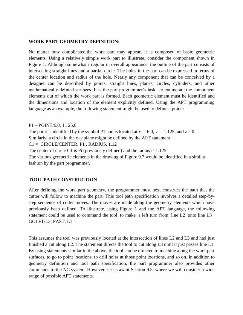
Machine code
The structure of a NC program written in machine code is standardized and for a two-axis NC
systemhas the following format:
NC program block consists of a number of program words. The NC program is executed block
by block:each next block is entered in the system and executed only after entirely completing the
current block.
Each program word is an ordered set of characteristics, letters and numbers, to specify a single
action ofthe machine tool. Program words fall into two categories,
Πmodal, which are active in the block in which they are specified and remain active in the
subsequent blocks until another program word overrides them;
• non-modal, which are only active in the block in which they are specified.
Some of the most important program words are as follows
sequence numbers (N****)
Sequence numbers are a means of identifying program blocks. In some systems they
are not required although sequence numbers are needed in most canned cycles (covered
later in this section);
preparatory functions (also G-codes) (G**)
Preparatory functions are used to set up the mode in which the rest of the operation
is to be executed.
Some of examples of G-codes are given in the table: G00 Positioning (not cutting)
G01 Linear interpolation
G02 Clockwise circular interpolation
G03 Counterclockwise circular interpolation
G20 Inch data input
G21 Metric data input
G54 Workpart coordinate preset
G80 Canned cycle cancel
G81-89 Canned cycles
G90 Absolute programming
G91 Incremental programming
Dimension words (D****.***), where D stands for X, Z, U, or WDimension words
specify the coordinate positions of the programmed path. X andZ specify the absolute
coordinates, and U and W specify the incremental coordinates(absolute and incremental
programming are explained later in this section);
Arc center coordinates (D****.***), where D stands for I, or KArc center coordinates
specify the incremental coordinate position of the arc center (I inthe direction of X-axis,
and K in the direction of Z-axis), measured from the arc startingpoint;
Feed function (F**.**)
Specifies the velocity of feed motion;
Spindle control function (S****)
Specifies spindle rotational speed in revolutions per minute, or cutting velocity in meterper
minute depending on the type of NC system and machine tool;
Tool calls (F**.**)
The tool call word is used to access the required tool. It also gives the information for theradial
compensation of tool corner wear for each new run of the program (and eachnew part);
Miscellaneous functions (M**)
The M-function performs miscellaneous machine actions such as these listed in thetable:
M00 Program stop
M02 Program end
M03 Start spindle CW
M04 Start spindle CCW
M05 Stop spindle
M06 Execute tool change
M07 Turn coolant on
M25 Open chuck
M26 Close chuck
Program points The NC system must know where the part is positioned in the work space. The procedure for defining the work coordinate system (WPC) is called work piece coordinate setting. Two important factors deal with work piece coordinate setting,
Πwhere the part datum (the origin of the WPC) is situated with respect to the work
piece; • Where the part datum is situated with respect to the machine tool. •
The WPC origin may be located at any part of the work piece, but to avoid dimensional recalculations and respectively errors, the good programmers will chose the WPC origin at the point, from where the part features are dimensioned:
•
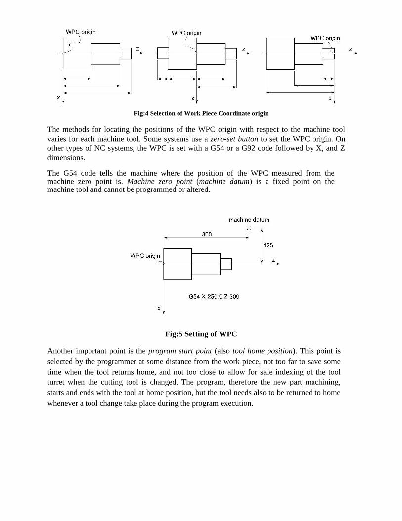
Fig:4 Selection of Work Piece Coordinate origin
The methods for locating the positions of the WPC origin with respect to the machine tool
varies for each machine tool. Some systems use a zero-set button to set the WPC origin. On
other types of NC systems, the WPC is set with a G54 or a G92 code followed by X, and Z
dimensions. The G54 code tells the machine where the position of the WPC measured from the machine zero point is. Machine zero point (machine datum) is a fixed point on the machine tool and cannot be programmed or altered.
Fig:5 Setting of WPC
Another important point is the program start point (also tool home position). This point is
selected by the programmer at some distance from the work piece, not too far to save some
time when the tool returns home, and not too close to allow for safe indexing of the tool
turret when the cutting tool is changed. The program, therefore the new part machining,
starts and ends with the tool at home position, but the tool needs also to be returned to home
whenever a tool change take place during the program execution.

Linear and circular interpolation A G01 linear interpolation code moves the tool to a position with coordinates defined with program words in a straight, including angular line at the specified with F-code feed rate. The command is modal and is active until either a G00, or G02, or G03 overrides it. NC system are capable of commanding a circular motion. Arc movement is known as circular interpola-tion and is carried out with a G02 (clockwise circular interpolation) or G03 (counter
clockwise circular interpolation) codes. The arc radius is specified either by the incremental dimensional words I and K, which defines the position of arc centerpoint with respect to the arc
start point, or directly by the radius R-code. In both methods, the program block, which starts
with a G02 or G03 codes must also include the coordinates of the arc end point. If R-code is used, arcs less than 180
o are given a positive radius and arcs more than 180
o are given a negative
radius value:
Fig:6 Linear and circular interpolation.
TOOL LENGTH COMPENSATION
Tool length compensation is instated with a G43 word. Included within the G43 command is an
H-word that specifies the offset number in which the tool length compensation value is stored.
You must also include a Z-word in the G43 command, telling the machine where you want the
tool tip to be positioned.
Cutting tools used on machining centers differ from one another. For one thing, there are a
variety of cutting tool types that are used on machining centers, including center drills, spot
drills, drills, taps, reamers, boring bars, end mills, and face mills (among many others). Each type
of tool requires a different way of gripping the actual cutting tool in its holder. Some tools (like
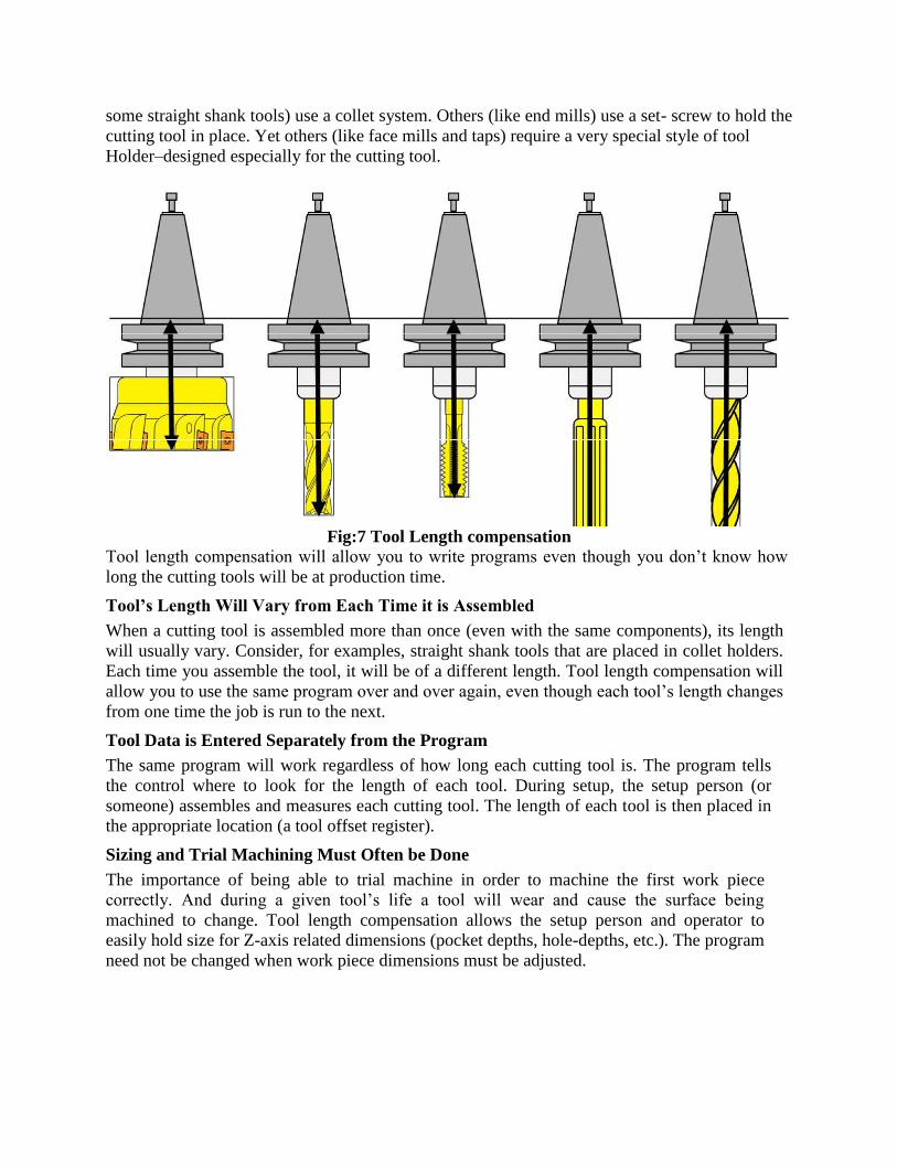
some straight shank tools) use a collet system. Others (like end mills) use a set- screw to hold the
cutting tool in place. Yet others (like face mills and taps) require a very special style of tool
Holder–designed especially for the cutting tool.
Fig:7 Tool Length compensation
Tool length compensation will allow you to write programs even though you don’t know how
long the cutting tools will be at production time. Tool’s Length Will Vary from Each Time it is Assembled When a cutting tool is assembled more than once (even with the same components), its length
will usually vary. Consider, for examples, straight shank tools that are placed in collet holders.
Each time you assemble the tool, it will be of a different length. Tool length compensation will
allow you to use the same program over and over again, even though each tool’s length changes
from one time the job is run to the next. Tool Data is Entered Separately from the Program The same program will work regardless of how long each cutting tool is. The program tells
the control where to look for the length of each tool. During setup, the setup person (or
someone) assembles and measures each cutting tool. The length of each tool is then placed in
the appropriate location (a tool offset register). Sizing and Trial Machining Must Often be Done The importance of being able to trial machine in order to machine the first work piece
correctly. And during a given tool’s life a tool will wear and cause the surface being
machined to change. Tool length compensation allows the setup person and operator to
easily hold size for Z-axis related dimensions (pocket depths, hole-depths, etc.). The program
need not be changed when work piece dimensions must be adjusted.

CUTTER RADIUS COMPENSATION
Cutter Radius Compensation also known as CRC, is a function of the CNC controller to
automatically shift the tool from the cutter center line to the cutter edge along the programmed
cutter path. If it were not for CRC the cutter path locations would have to be calculated to the
cutter center line. Cutter Radius Compensation (CRC) can be used to program continuous path
milling operations.
There are a few special rules that must be applied to the programming method when using CRC.
1) The point before the CRC approach and exit from the contour cut must be equal to or
greater than the cutter radius.
2) CRC can only be started and stopped along linear motion.
3) CRC can only be applied to 2 axis of motion at a time.
4) The use of more than one non motion block in a row is not allowed.
Three main advantages to using Cutter Radius Compensation (CRC) programming
1)The programmer can use point values that are directly along the cutter path rather than having
to calculate the tool center.
2)During production runs, cutters of different sizes can be used such as undersize tools when the
original size tool is no longer available. It is a simple radius offset value change in the machine
control to achieve this. The programming will remain the same.
3)A program section or operation can be used over and over with different tools to create
roughing passes and finish passes. This is done by changing the radius offset value and using
multiple offsets.
TOOL NOSE RADIUS COMPENSATION
During processing of the work piece contour, due to the tool radius, tip and a half Diameter of
the existence of the tool tip and work piece center or imaginary contours do
not coincide. If the digital system does not have automatic tool radius compensation
function can only be converted into contour programming tool center path, and then
processed. When the tool wear, heavy wear, tool change, to re-calculate the tool center
path, modify the program. However, when the numerical control system with automatic tool
radius compensation function, you can just press the work piece contour programming,
CNC system will automatically calculate the tool center path, deviate from the contour of
the tool with a radius value, even if the tool wear, heavy wear, tool change, also need to
modify the radius of the tool deviate from the contour value that offsets, tool radius
compensation automatically, without modifying the program.
CNC lathe programming is based on imaginary tip movement; the actual tip location is a
small circular, conical surface and in the turning arc will produce processing errors. If the use of
nose radius compensation, pre-tip to tip radius and arc parameters such as input to the tool
position within the database, according to work piece contour programming, numerical control
system automatically calculates the tool center trajectory, the control center path for cutting
knives processing, eliminating the tip of the arc caused by processing errors. You can also
modify the value to eliminate abrasion tool wear or tool failure caused by processing errors.
Similarly, in CNC milling, the tool radius offset pre-register in the specified register, the
use of the tool radius compensation commands, by adjusting the tool radius compensation value
to compensate for tool wear, in order to eliminate the tool wear caused by processing errors . At
the same time even if a replacement tool or tool re-grinding, as long as the contour is the same,
processing the same coordinate system, you can use the original program. At the same time as
the application can also adjust the tool radius compensation amount to the same profile using the
same procedures under the same conditions, rough and finish.
Cycles
The repetitive program (and machining) sequence is called a cycle. Cycles are classified into two
principlegroups,
Πcanned cycles (also fixed cycles), and user-defined cycles (sub-routines).
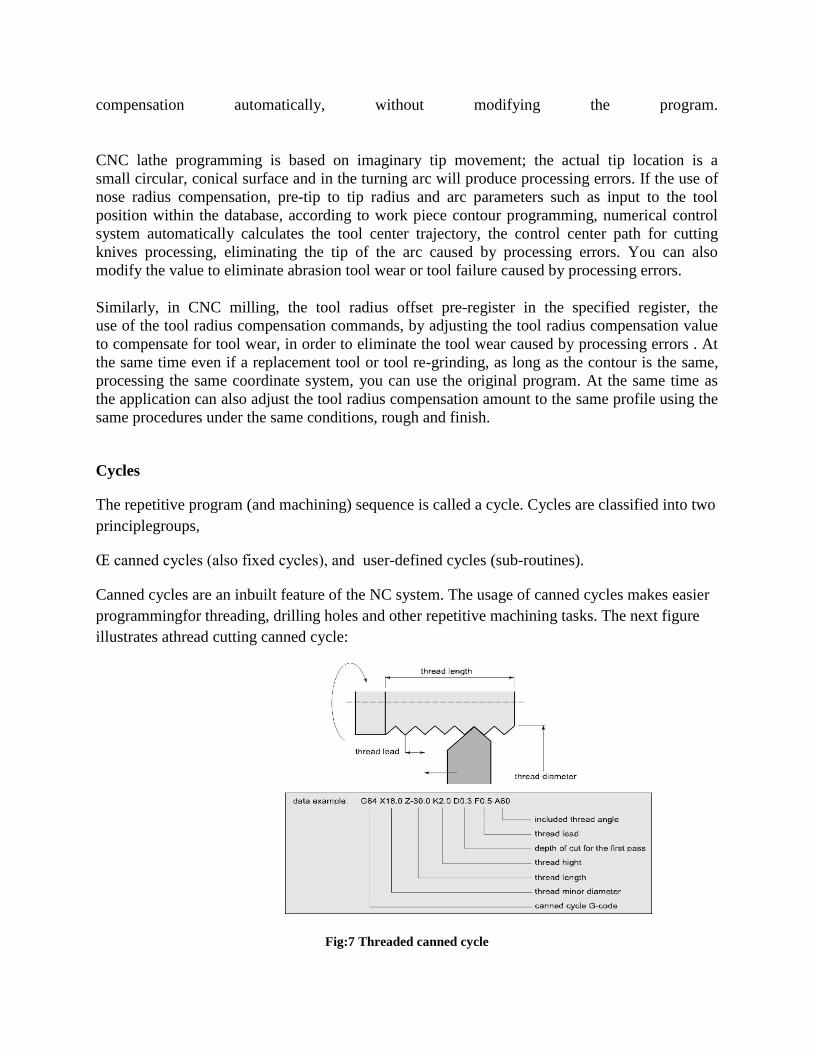
Canned cycles are an inbuilt feature of the NC system. The usage of canned cycles makes easier
programmingfor threading, drilling holes and other repetitive machining tasks. The next figure
illustrates athread cutting canned cycle:
Fig:7 Threaded canned cycle

User sub-routines are useful, when the necessary canned cycle is not available. The user sub-
routine is a NC program, which describes a sequence of operations, which is often repeated
when machining particular part. The sub-routine is called from the main NC program with a
M98 command. A special type of user-defined cycles is so-called macros, which are generic cycles with parametric variables. The macro is called from the main program with a set of numerical values for these variables. This allow to use one and the same macro to machine different in size, but similar in shape components. Programming with macros is often referred to as a parametric programming.
Mirror Image
The mirroring command is used when features of components shares symmetry about one or
more axes and are also dimensionally identical. By using this code components can be machined
using a single set of data and length of programs can be reduced.
G10 cancellation of mirroring image
G11 Mirror image on X axis
G12 Mirror image on Y axis
G13 Mirror image on Z axis
Fig. 8 Illustrative Example for mirroring

Parametric Programming
Parametric programming can be compared to any computer programming language like BASIC,
C Language, and PASCAL. However, this programming language resides right in the CNC
control and can be accessed at G code level, meaning you can combine manual programming
techniques with parametric programming techniques. Computer-related features like variables,
arithmetic, logic statements, and looping are available. Like computer programming languages,
parametric programming comes in several versions. The most popular is Custom Macro B (used
by Fanuc and Fanuc-compatible controls). Others include User Task (from Okuma), Q Routine
(from Sodick), and Advanced Programming Language [APL] (from G& L)
In addition to having many computer-related features, most versions of parametric programming
have extensive CNC-related features. Custom macro, for example, allows the CNC user to access
many things about the CNC control (tool offsets, axis position, alarms, generate G codes, and
program protection) right from within a CNC program. These things are impossible with only
normal G code programming techniques.
Applications: Many companies have excellent applications for custom macro and don't even know it. Of
course, if you don't even know you have an application for something, it's impossible to even
consider using it. While these applications are covered in much greater detail during our video
course and CD-rom course, applications for custom macro fall into five basic categories.
Example: To stress what can be done with parametric programming, we show a simple example written in
custom macro B for a machining center application. It will machine a mill a hole of any size at
any location. Notice how similar this program is to a program written in BASIC.
Program
O0001 (Program number)
#100=1. (Diameter of end mill)
#101=3.0 (X position of hole)
#102=1.5 (Y position of hole)
#103=.5 (Depth of counter bored hole)
#104=400 (Speed in RPM)
#105=3.5 (Feed rate in IPM)
#106=3. (Tool length offset number)
#107=2.0 (Diameter of counter bored hole)
G90 G54 S#104 M03 (Select abs mode, coordinate system, start spindle)
G00 X#101 Y#102 (Rapid to hole center)
G43 H#106 Z.1 (Instate tool length compensation, rapid to approach Z position)
G01 Z-#103 F[#105 / 2]
Y[#102 + #107 / 2 - #100 / 2] F#105
G02 J-[#107 / 2 - #100 / 2]
G01 Y#102
G00 Z.1
M30
Automatically Programmed Tool (APT)
The API language was the product of the MIT developmental work on NC programming
systems. Its development began in June 1956, and it was first used in production around 1959.
Today it is the most widely used language in the United States. Although first intended as a
contouring language, modern versions of APT can be used for both positioning and continuous-
path programming and continuous-path programming in up to five axes.
AUTOSPOT (AUTOMATIC SYSTEM FOR POSITIONNING TOOLS). This was developed
by IBM and first introduced in 1962 for PTP programming. Today’s version of AUTOSPOT can
be used for contouring as well.
SPLIT (SUNDSTRAND PROCESSING LANGUAGE INTERNALLY TRANSLATED). This
is a proprietary system intended for Sundstrand’s machine tools. It can handle up to five axis
positioning and possesses contouring capability as well. One of the unusual features of SPLIT is
that the post processor is built into the program. Each machine tool uses its own SPLIT package,
thus obviating the need for a special post processor.
COMPACT II. This is a package available from Manufacturing Data Systems, Inc. (MDSI), a
firm based in Ann Arbor, Michigan. The NC language is similar to SPLIT in many of its
features. MDSI leases the COMPACT II system to its users on a time-sharing basis. The part
programmer uses a remote terminal to feed the program into one of the MDSI computers, which
in tum produces the NC tape.

ADAPT (ADAPTATION OF APT). Several part programming languages are based directly on
the APT program One of these is ADAPT, which was developed by IBM under Air Force
contract. It was intended to provide many of the features of AFT but to utilize a significantly
smaller computer. ADAPT is not as powerful as APT, but can be used to program for both
positioning and contouring jobs.
EXAPT (EXENDED SUBSET OF APT). This was developed in Germany starting around
1964 and is based on the APT language. Itere are three versions: EXAPT I designed for
positioning (drilling and also straight-cut milling), EXAPT ll designed for turning, and EXAPT
III designed for limited contouring operations. One of the important features of EXAPT is that it
attempts to compute optimum feeds and speeds automatically.
PART PROGRAMMING USING CAD/CAM
A CAD/CAM system is a computer interactive graphics system equipped with software to
accomplish certain tasks in design and manufacturing functions. One of the important tasks
performed on a CAD/CAM system is NC part programming. In this method of part
programming, portions of the procedure usually done by the part programmer are instead done
by the computer. The two main tasks of a part programmer in a computer assisted programming
are (a) defining the part geometry and (b) specifying the tool path. The proposed methodology
is used to automate both of these tasks.
Part geometry definition:
The fundamental objective of CAD/CAM system is to integrate the design engineering and
manufacturing engineering functions. Certainly one of the important design functions is to
design the individual components of the product. If a CAD/CAM system is used, a computer g
raphics model of each part is developed by the designer and stored in the CAD/CAM database.
That model contains all of the geometric, dimensional and material specifications for the part.
When the same CAD/CAM system, or a CAM system that has access to the same CAD database
in which the part model resides, is used to perform NC part programming it makes little sense to
re create the geometry of the part during the programming procedure. Instead, the programmer
has the capability to retrieve the part geometry model from the storage and to use that model to
construct the appropriate cutter path. The significant advantage of using CAD/CAM in this way
is that it eliminates one of the time consuming steps in computer assisted part programming
geometry definition.
After the part geometry has been retrieved, the usual procedure is to label the geometric elements
that will be used during part programming. These labels are the variable names (symbols) given
to the lines circles and surfaces that comprise the part. Most systems have the capacity to
automatically label the geometry elements of the part and to display the labels on the dias.
If the NC programmer does not have access to the data base, then the NC Programming must be
defined. This is done by using similar interactive graphics techniques that the product designer
would use to design the part. Points are defined in a coordinate system using the computer
graphics system, lines and circles are defined from the points, surfaces are defined, and so forth,

to construct a geometric model of the part. The advantage of using the interactive graphics
system over conventional computer assisted part programming is that the programmer receives
immediate visual verification of the definitions being created. This tends to improve the speed
and accuracy of the geometry definition process.
Tool path generation using CAD/CAM:
The second task of the NC programmer in computer assisted part programming is tool path
Specification. The first step in specifying the tool path is to select the cutting tool for the
operation. Most CAD/CAM systems have tool libraries that can be called by the programmer to
identify what tools are available in the tool crib. The programmer must decide which of the
available tools is most appropriate for the operation under consideration and specify it for the
tool path. This permits the tool diameter and other dimensions to be entered automatically for
tool offset calculations. If the desired cutting tool is not available in the library, an appropriate
tool can be specified by the programmer. It then becomes part of the library for future use.
The next step is tool path definition. There are differences in capabilities of the various
CAD/CAM systems, which result in different approaches for generating the tool path. The most
basic approach involves the use of the interactive graphics system to enter the motion
Commands one by one, similar to computer assisted part programming. Individual statements in
APT or other part programming language are entered and the CAD/CAM system provides an
immediate graphic display of the action resulting from the command, thereby validating the
statement. A more advanced approach for generating tool path commands is to use one of the
automatic software modules available on the CAD/CAM system. These modules have been
developed to accomplish a number of common machining cycles for milling, drilling and
turning. They are subroutines in the NC programming package that can be called and the
Required parameters given to execute the machining cycle.
Computer Automated part programming:
In the CAD/CAM approach to NC part programming, several aspects of the procedure are
automated. In the future, it should be possible to automate the complete NC part programming
procedure. The proposed system is an automated system where the input is a geometric model of
a part that has been defined during product design and the output is a NC part program. The
system possesses sufficient logic and decision making capability to accomplish NC part
programming for the entire part without human assistance.
This can most readily be done for certain NC processes that involve well defined, relatively
medium complex part geometries. Special algorithms have been developed to process the
design data and generate the NC program.