unit price w) - optcl · 2019-05-30 · (circuit breaker shall be e2-c2-m2 class as per iec...
TRANSCRIPT

In Foreign
CurrencyCIP
(1) (2) (3) (1) x (3)
1
3150A, 50kA for 3s, Double Busbar Circuit Breaker
(Circuit breaker shall be E2-C2-M2 class as per IEC 62271-
100) arrangement.245kV OUTDOOR GIS EQUIPMENT as
per latest IEC standard & type tested equipment as per
technical specification, with open future proof & flexible
system in line with IEC 61850 & IEC 62271-203.
ODISHA POWER TRANSMISSION CORPORATION LIMITED
Unit Price2
Qu
an
tity
fo
r: C
on
str
uc
tio
n o
f 2
x1
60
MV
A
Au
to T
ran
sfo
rme
r, 2
20
/13
2 G
IS S
/S a
t
(Gu
nd
ich
ap
ad
a)
Dh
en
ka
na
l O
ut
Do
or
typ
e G
IS S
/S (
Ne
w)
Total Price2
NAME OF THE WORK:-Design, Supply and Installation of 2X160MVA Auto Transformer ,220/132 KV Out Door Type GIS Grid Sub-station at
(Gundichapada),Dhenkanal and 2 nos. 132KV Feeder bay extension at existing 132/33KV Dhenkanal grid sub-station for connectivity with
Dhenkanal GIS in Odisha State of India under PACKAGE-1 Under Japan International Cooperation Agency (JICA)’s ODA Loan.
Loan Agreement No: [ID-P245] - FB No: [CPC/JICA/ICB/01/18-19]- Reference Identification No: [OPTCL/JICA/PKG-1]
Schedule No. 1. Plant Supplied from Abroad (Sub-station )
UNITCode1SL. NO.
NAME OF THE BIDDER
SUPPLY OF FOLLOWING EQUIPMENTS
(As per Technical Specification)

1.1
245kV, 3150A, 50kA for 3 sec (Busbar, CB, Disconnector,
Grounding Switch & CT), SF6 gas insulated Transformer
Feeder Bay Module each comprising of SF6 gas insulated
Single Pole Circuit Breaker (1 Set), Single Phase Current
Transformer (6 Nos), Motorised Busbar 3 Phase Disconnector
(2 Nos), Motorised Disconnector (1 No), Motorised safety
Grounding switch (3 Nos), Local Control Cubicle, SF6 gas
monitoring system for complete bay, SF6 bus duct termination
arrangement (3 Nos), PD sensor (adequate number of UHF
sensors in the offered GIS equipment for detection of Partial
discharge (of 5 pC and above) as per IEC 60270 through
Partial Discharge (PD) monitoring system), different gas
compartment, O-ring & gaskets, Nuts, Bolts & Washers for
Outdoor use, Absorbent, Limit Switch, SF6 Gas, etc. to
complete ICT Feeder Bay Module & its earthing arrangement
with earthing strips of adequate size (as per IEEE Std 80-2013
to protect operating staff against any hazardous touch
voltages and electro-magnetic interferences) as per the
technical specification(Price of the equipment has been
converted from Japanese Yen to INR as per the selling rate
on Dt.18.12.2018)
Set 2

1.2
245kV, 3150A, 50kA for 3 sec (Busbar, CB, Disconnector,
Grounding switch, CT & PT), SF6 gas insulated Line Feeder
Bay Module each comprising of SF6 gas insulated Single Pole
Circuit Breaker (1 Set), Single Phase Current Transformer (6
Nos), Single phase Line Potential Transformer (4 winding) (3
Nos), Motorised 3 Phase Busbar Disconnector (2 Nos),
Motorised safety Grounding switch (2 Nos), Motorised 3
Phase Disconnector with high speed fault making Motorised
Grounding switch (1 No), Local Control Cubicle, SF6 gas
monitoring system for complete bay, SF6 bus duct termination
arrangement (3 Nos), PD sensor (adequate number of UHF
sensors in the offered GIS equipment for detection of Partial
discharge (of 5 pC and above) as per IEC 60270 through
Partial Discharge (PD) monitoring system), different gas
compartment, O-ring & gaskets, Nuts, Bolts & Washers for
Outdoor use, Absorbent, Limit Switch, SF6 Gas, etc. to
complete Line Feeder Bay Module & its earthing arrangement
with earthing strips of adequate size (as per IEEE Std 80-2013
to protect operating staff against any hazardous touch
voltages and electro-magnetic interferences) as per the
technical specification.
Set 4

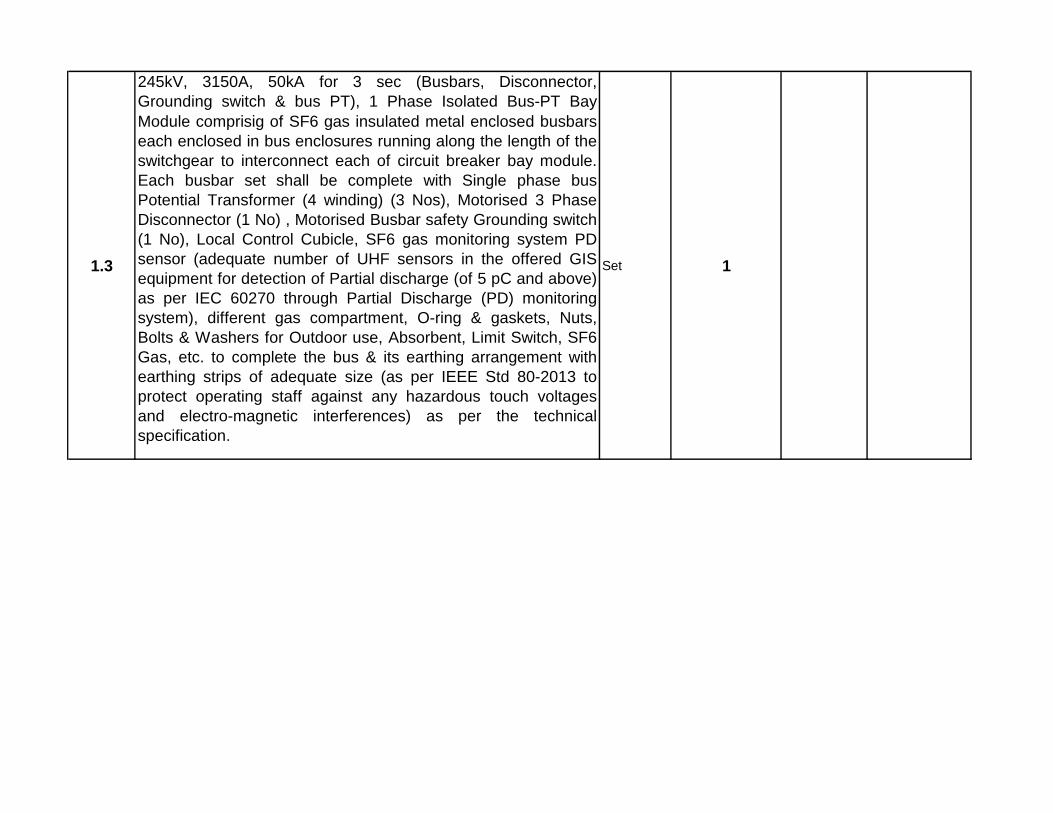
1.3
245kV, 3150A, 50kA for 3 sec (Busbars, Disconnector,
Grounding switch & bus PT), 1 Phase Isolated Bus-PT Bay
Module comprisig of SF6 gas insulated metal enclosed
busbars each enclosed in bus enclosures running along the
length of the switchgear to interconnect each of circuit breaker
bay module. Each busbar set shall be complete with Single
phase bus Potential Transformer (4 winding) (3 Nos),
Motorised 3 Phase Disconnector (1 No) , Motorised Busbar
safety Grounding switch (1 No), Local Control Cubicle, SF6
gas monitoring system PD sensor (adequate number of UHF
sensors in the offered GIS equipment for detection of Partial
discharge (of 5 pC and above) as per IEC 60270 through
Partial Discharge (PD) monitoring system), different gas
compartment, O-ring & gaskets, Nuts, Bolts & Washers for
Outdoor use, Absorbent, Limit Switch, SF6 Gas, etc. to
complete the bus & its earthing arrangement with earthing
strips of adequate size (as per IEEE Std 80-2013 to protect
operating staff against any hazardous touch voltages and
electro-magnetic interferences) as per the technical
specification.
Set 1
1.4
245kV, 3150A, 50kA for 3 sec (CB, Disconnector, Grounding
switch & CT), SF6 gas insulated Bus Coupler Bay Module
comprising of SF6 gas insulated Single Pole Circuit Breaker
(1 Set), Single Phase Current Transformer (6 Nos), Motorised
3 Phase Disconnector (2 Nos), Motorised safety Grounding
switch (2 Nos), Local Control Cubicle, SF6 gas monitoring
system, PD sensor (adequate number of UHF sensors in the
offered GIS equipment for detection of Partial discharge (of 5
pC and above) as per IEC 60270 through Partial Discharge
(PD) monitoring system), different gas compartment, O-ring &
gaskets, Nuts, Bolts & Washers for Outdoor use, Absorbent,
Limit Switch, SF6 Gas, etc. to complete Bus Coupler Bay
Module & its earthing arrangement with earthing strips of
adequate size (as per IEEE Std 80-2013 to protect operating
staff against any hazardous touch voltages and electro-
magnetic interferences) as per the technical specification.
Set 1

1.5
245kV, 3150A, 50 kA, 3 sec, single phase, SF6 gas Insulated
Bus Duct outside GIS Bay along with associated Support
structure arrangement bends, joints,accessories, & its
earthing arrangement with earthing strips of adequate size (as
per IEEE Std 80-2013 to protect operating staff against any
hazardous touch voltages and electro-magnetic interferences)
as per the technical specification.
RM 700
1.6
245kV, 3150A, 50kA SF6/Air BUSHING (Bushing shall be of
Polymer / composite insulator type and shall be seamless
sheath of a silicone rubber compound. The hollow silicone
composite insulators shall comply as per IEC 61462 and IEC
62217. The design of the composite insulators shall be tested
and verified according to IEC 61462) FOR CONNECTING
GIS TO AIS along with support structure.
No. 18
1.7
Portable Partial Discharge Monitoring System (PDM):
245kV system shall have Portable Partial Discharge
Monitoring System (PDM) & shall be capable for measuring
PD in charged GIS environment, bandwidth in order of
100MHz–2GHz & provision to select a wide range of
intermediate bandwidths and the principle of operation shall
be based on UHF principle of detection. The Detection and
measurement of PD and bouncing particles having in built
large coloured LCD for displaying and storing facility in the
instrument for further analysis to locate actual source of PD
such as free conducting particles, floating components, voids
in spacers, particle on spacer surfaces etc.
Set 1
2
2000A, 40kA for 3s, Double Busbar Circuit Breaker
(Circuit breaker shall be E2-C2-M2 class as per IEC 62271-
100) arrangement.
145kV OUTDOOR GIS EQUIPMENT as per latest IEC
standard & type tested equipment as per technical
specification, with open future proof & flexible system in
line with IEC 61850 & IEC 62271-203.

2.1
145kV, 2000A, 40kA for 3 sec (Busbar, CB, Disconnector,
Grounding Switch & CT), SF6 gas insulated Transformer
Feeder Bay Module each comprising of SF6 gas insulated
Single Pole Circuit Breaker (1 Set), Single Phase Current
Transformer (6 Nos), Motorised Busbar 3 Phase Disconnector
(2 Nos), Motorised Disconnector (1 No), Motorised safety
Grounding switch (3 Nos), Local Control Cubicle, SF6 gas
monitoring system for complete bay, SF6 bus duct termination
arrangement (3 Nos), PD sensor (adequate number of UHF
sensors in the offered GIS equipment for detection of Partial
discharge (of 5 pC and above) as per IEC 60270 through
Partial Discharge (PD) monitoring system), different gas
compartment, O-ring & gaskets, Nuts, Bolts & Washers for
Outdoor use, Absorbent, Limit Switch, SF6 Gas, etc. to
complete ICT Feeder Bay Module & its earthing arrangement
with earthing strips of adequate size (as per IEEE Std 80-2013
to protect operating staff against any hazardous touch
voltages and electro-magnetic interferences) as per the
technical specification.
Set 2

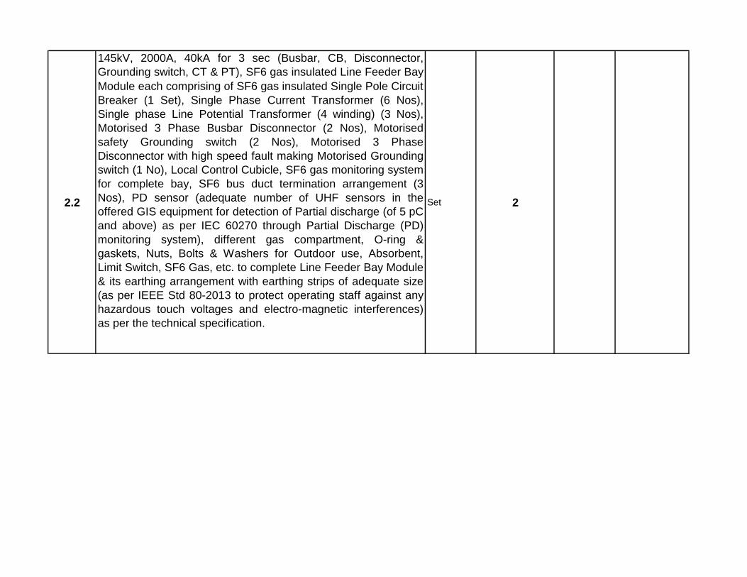
2.2
145kV, 2000A, 40kA for 3 sec (Busbar, CB, Disconnector,
Grounding switch, CT & PT), SF6 gas insulated Line Feeder
Bay Module each comprising of SF6 gas insulated Single Pole
Circuit Breaker (1 Set), Single Phase Current Transformer (6
Nos), Single phase Line Potential Transformer (4 winding) (3
Nos), Motorised 3 Phase Busbar Disconnector (2 Nos),
Motorised safety Grounding switch (2 Nos), Motorised 3
Phase Disconnector with high speed fault making Motorised
Grounding switch (1 No), Local Control Cubicle, SF6 gas
monitoring system for complete bay, SF6 bus duct termination
arrangement (3 Nos), PD sensor (adequate number of UHF
sensors in the offered GIS equipment for detection of Partial
discharge (of 5 pC and above) as per IEC 60270 through
Partial Discharge (PD) monitoring system), different gas
compartment, O-ring & gaskets, Nuts, Bolts & Washers for
Outdoor use, Absorbent, Limit Switch, SF6 Gas, etc. to
complete Line Feeder Bay Module & its earthing arrangement
with earthing strips of adequate size (as per IEEE Std 80-2013
to protect operating staff against any hazardous touch
voltages and electro-magnetic interferences) as per the
technical specification.
Set 2

2.3
145kV, 2000A, 40kA for 3 sec (Busbars, Disconnector,
Grounding switch & bus PT), 1 Phase Isolated Bus-PT Bay
Module comprisig of SF6 gas insulated metal enclosed
busbars each enclosed in bus enclosures running along the
length of the switchgear to interconnect each of circuit breaker
bay module. Each busbar set shall be complete with Single
phase bus Potential Transformer (4 winding) (3 Nos),
Motorised 3 Phase Disconnector (1 No) , Motorised Busbar
safety Grounding switch (1 No), Local Control Cubicle, SF6
gas monitoring system PD sensor (adequate number of UHF
sensors in the offered GIS equipment for detection of Partial
discharge (of 5 pC and above) as per IEC 60270 through
Partial Discharge (PD) monitoring system), different gas
compartment, O-ring & gaskets, Nuts, Bolts & Washers for
Outdoor use, Absorbent, Limit Switch, SF6 Gas, etc. to
complete the bus & its earthing arrangement with earthing
strips of adequate size (as per IEEE Std 80-2013 to protect
operating staff against any hazardous touch voltages and
electro-magnetic interferences) as per the technical
specification.
Set 1
2.4
145kV, 2000A, 40kA for 3 sec (CB, Disconnector, Grounding
switch & CT), SF6 gas insulated Bus Coupler Bay Module
comprising of SF6 gas insulated Single Pole Circuit Breaker
(1 Set), Single Phase Current Transformer (6 Nos), Motorised
3 Phase Disconnector (2 Nos), Motorised safety Grounding
switch (2 Nos), Local Control Cubicle, SF6 gas monitoring
system, PD sensor (adequate number of UHF sensors in the
offered GIS equipment for detection of Partial discharge (of 5
pC and above) as per IEC 60270 through Partial Discharge
(PD) monitoring system), different gas compartment, O-ring &
gaskets, Nuts, Bolts & Washers for Outdoor use, Absorbent,
Limit Switch, SF6 Gas, etc. to complete Bus Coupler Bay
Module & its earthing arrangement with earthing strips of
adequate size (as per IEEE Std 80-2013 to protect operating
staff against any hazardous touch voltages and electro-
magnetic interferences) as per the technical specification.
Set 1

2.5
Portable Partial Discharge Monitoring System (PDM):
145kV system shall have Portable Partial Discharge
Monitoring System (PDM) & shall be capable for measuring
PD in charged GIS environment, bandwidth in order of
100MHz–2GHz & provision to select a wide range of
intermediate bandwidths and the principle of operation shall
be based on UHF principle of detection. The Detection and
measurement of PD and bouncing particles having in built
large coloured LCD for displaying and storing facility in the
instrument for further analysis to locate actual source of PD
such as free conducting particles, floating components, voids
in spacers, particle on spacer surfaces etc.
Set 1
3 245 KV,2000A,40KA,ISOLATORS
3.1 245 KV, 2000A, 40KA, Center break ISOLATORS WITH EARTH SWITCH NOS 4
4 216 KV, METAL OXIDE SURGE ARRESTOR,10 KA, class III NOS 18
5 220 KV Bus Post Insulators NOS 6
6 145 KV,1250A,31.5KA,ISOLATORS
6.1 145 KV, 2000A, 40KA, Center break ISOLATORS WITH EARTH SWITCH NOS 2
7 120 KV METAL OXIDE SURGE ARRESTOR, 10 KA, Class III NOS 12
830 KV, METAL OXIDE SURGE ARRESTOR, 10kA, Class II (AIS) as per
technical specification.NOS 9
9 BUS BAR & CIRCUIT MATERIALS
9.1 LONG ROD ANTI FOG PORCELAIN INSULATORS
9.1.1 120 KN INSULATOR NOS 24
9.1.2 90 KN INSULATOR NOS 6
9.2 ACSR MOOSE CONDUCTOR KMS 3.2
10 HARDWARES & FITTINGS/SPACERS/CLAMP & CONNECTORS
10.1 220 KV Single Suspension(120 KN)H/W fitting for Twin Moose ACSR NOS 12
10.2 132 KV Single Suspension(90KN) H/W fitting for single Moose ACSR NOS 6
10.3 T- clamp for ACSR ZEBRA run to ACSR MOOSE drop NOS 36
10.4 T- clamp for ACSR PANTHER run to ACSR MOOSE drop NOS 18
10.5 220 KV PI clamp NOS 6
10.6 Spacer for Moose ACSR NOS 36
10.7 220 KV Isolator pad clamp NOS 12
10.8 220 KV LA Clamp NOS 18
10.9 132 KV Isolator pad clamp NOS 6
10.10 132 KV LA Clamp NOS 12
10.11 PG Clamp for ACSR Moose NOS 108

11
XLPE Power Copper conductor cable for the GIS system (for
132 KV connectivity from GIS equipment to Auto Transformer
& Gantry of Existing 132/33KV S/S)
11.1132KV XLPE Copper Cable 1000 sq. mm Single Core (from 132
KV GIS to 132KV Gantry)Mtrs 3000
11.2132KV Cable termination kits (Outdoor GIS side) suitable for 1CX
1000 sq. mm Copper CableNOS 12
11.3132 KV Cable termination kit including Cable to Air Bushing suitable for
outdoor for 132 KV Feeders & Transformers suitable for 1CX1000 Sqmm copper
cable.
NOS 12
11.4EHV cable accessories like, link box, SVL, bonding cables, earthing
cable for 132 kV system as per tech specification.LOT 1
11.533KV XLPE Copper Cable 300 sq. mm Single Core (For
connectivity to Station Transformer)Mtrs 1000
11.633 KV Cable termination kit including Cable to Air Bushing suitable for
outdoor for 33 KV suitable for 1CX300 Sqmm copper cable.NOS 12
12 EARTH WIRES & IT'S HARDWARES & FITTING
12.1Earthing Spikes of 9 mtr long each and Its Fittings in all respect. (220 kv
side)NOS 5
12.2Earthing Spikes of 7 mtr long each and Its Fittings in all respect. (132 kv
side)NOS 3
13 SUBSTATION EARTHING SYSTEMS
13.1EARTHING CONDUCTOR FOR BURRIAL : 75X10 mm GI Flat for laying
(spacing maximum 5m both way ) MT 48.000
13.2EARTHING CONDUCTOR: 50X6 mm GI Flat for Raiser from the burial
earth mat to equipment,structure etc)MT 4.000
13.3EARTHING DEVICE & ASSOCIATED ACCESSORIES (50 mm heavy
duty GI PERFORATED PIPE 3 mtrs long for treated earth pit)Nos. 50
13.4EARTHING DEVICE & ASSOCIATED ACCESSORIES 40mm MS rod 3
mtrs long for non treated earth pit)Nos. 120
14
G.I Cable Trays including support GI angle suitable for different sections
i.e. Section:1-1,2-2,3-3 & 4-4 along with its accessories as per TS.
14.1 G.I Cable Trays(size: 450x75x2500mm) MTRS 2000
14.2 G.I Cable Trays(size: 300x75x2500mm) MTRS 2500
14.3 G.I Cable Trays(size: 150x75x2500mm) MTRS 2000
14.4 Support G. I angle 50x50x6 mm for cable tray MT 4
15SUB STATION SWITCYARD BMK,AC CONSOLE & OTHER
MARSHALLING BOXES
15.1BAY MARSHALLING KIOSK (02 Nos. in 220 KV Bay,01 Nos. in 132 KV
Bay BAY )NOS 3
15.2SWITCH YARD AC CONSOLE FOR LIGHTING (01 Nos. in 220 KV bay,
01 No. in 132 kv Bay )NOS 2
15.3SWITCH YARD RECEPTACLE BOARD FOR TFR OIL FILTERATION
(01 No. near each 220/132 Auto Transformers)NOS 2
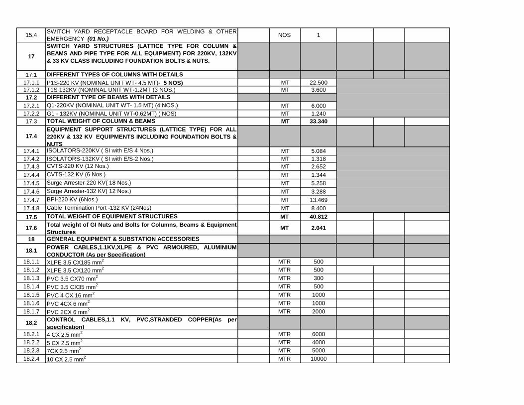
15.4SWITCH YARD RECEPTACLE BOARD FOR WELDING & OTHER
EMERGENCY (01 No.)NOS 1
17
SWITCH YARD STRUCTURES (LATTICE TYPE FOR COLUMN &
BEAMS AND PIPE TYPE FOR ALL EQUIPMENT) FOR 220KV, 132KV
& 33 KV CLASS INCLUDING FOUNDATION BOLTS & NUTS.
17.1 DIFFERENT TYPES OF COLUMNS WITH DETAILS
17.1.1 P1S-220 KV (NOMINAL UNIT WT- 4.5 MT)- 5 NOS) MT 22.500
17.1.2 T1S 132KV (NOMINAL UNIT WT-1.2MT (3 NOS.) MT 3.600
17.2 DIFFERENT TYPE OF BEAMS WITH DETAILS
17.2.1 Q1-220KV (NOMINAL UNIT WT- 1.5 MT) (4 NOS.) MT 6.000
17.2.2 G1 - 132KV (NOMINAL UNIT WT-0.62MT) ( NOS) MT 1.240
17.3 TOTAL WEIGHT OF COLUMN & BEAMS MT 33.340
17.4
EQUIPMENT SUPPORT STRUCTURES (LATTICE TYPE) FOR ALL
220KV & 132 KV EQUIPMENTS INCLUDING FOUNDATION BOLTS &
NUTS
17.4.1 ISOLATORS-220KV ( SI with E/S 4 Nos.) MT 5.084
17.4.2 ISOLATORS-132KV ( SI with E/S-2 Nos.) MT 1.318
17.4.3 CVTS-220 KV (12 Nos.) MT 2.652
17.4.4 CVTS-132 KV (6 Nos ) MT 1.344
17.4.5 Surge Arrester-220 KV( 18 Nos.) MT 5.258
17.4.6 Surge Arrester-132 KV( 12 Nos.) MT 3.288
17.4.7 BPI-220 KV (6Nos.) MT 13.469
17.4.8 Cable Termination Port -132 KV (24Nos) MT 8.400
17.5 TOTAL WEIGHT OF EQUIPMENT STRUCTURES MT 40.812
17.6Total weight of GI Nuts and Bolts for Columns, Beams & Equipment
Structures MT 2.041
18 GENERAL EQUIPMENT & SUBSTATION ACCESSORIES
18.1POWER CABLES,1.1KV,XLPE & PVC ARMOURED, ALUMINIUM
CONDUCTOR (As per Specification)
18.1.1 XLPE 3.5 CX185 mm2 MTR 500
18.1.2 XLPE 3.5 CX120 mm2 MTR 500
18.1.3 PVC 3.5 CX70 mm2 MTR 300
18.1.4 PVC 3.5 CX35 mm2 MTR 500
18.1.5 PVC 4 CX 16 mm2 MTR 1000
18.1.6 PVC 4CX 6 mm2 MTR 1000
18.1.7 PVC 2CX 6 mm2 MTR 2000
18.2CONTROL CABLES,1.1 KV, PVC,STRANDED COPPER(As per
specification)
18.2.1 4 CX 2.5 mm2 MTR 6000
18.2.2 5 CX 2.5 mm2 MTR 4000
18.2.3 7CX 2.5 mm2 MTR 5000
18.2.4 10 CX 2.5 mm2 MTR 10000

18.2.5 12 CX 2.5 mm2 MTR 5000
18.2.6 16 CX 2.5 mm2 MTR 2000
18.2.7 19 CX 2.5 mm2 MTR 2000
18.2.8 1CX 120 mm2
BAT TO BAT CHARGER & CHARGER TO DCDB MTR 300
19 ACCESSORIES FOR PLCC SYSTEM With OPGW cable
19.1 48 Fibre Optic Approach cable along with HDPE Pipes KM 0.50
19.2 Optical line Terminal Equipment(OLTE) -STM4 type SDH equipment with
integrated MUX & tributary cards for speech & data ports for interfacing
of Speech & data which should be compatible with existing OPTCL
system
No
1
19.3 Digital Teleprotection Equipment and accessories to be suitable for
interfacing with SDHMUX
No1
19.4 Supply of FODP(Fibre Optic Distribution Panel)48 F: Indoor type,rack
mounted with FCPC coupling and pig tails(DWSm Fibre)
No1
19.5 48 V, 300 AH, maintenance free VRLA Battery set. Set 1
19.6SMPS based Battery Charger of 75A suitable for 48V VRLA Battery set No 1
19.7 2.5 sq. mm muti strand 2 core control cable(power
supply,Transducer/MFT PT supply)Metre 300
19.82.5 sq. mm multi strand 4 core control cable(Transducer/MFT CT supply) Metre 300
19.9 1.5 sq. mm multi strand 10 core control cable(Digital Input) Metre 200
19.10 10 sq. mm 2 core multi strand control cable(Battery) Metre 100
19.11 48V DCDB Set 1
19.12Earth Flat, Cable Tray, Telephone cable, Foundation rail, Junction Box,. Lot 1
20 SUPPLY OF POWER TRANSFORMER,STATION TRANSFORMER &
OTHER MATERIALS FOR MEETING THE AUXILIARY SUPPLY OF
THE SUB-STATION AS PER TECHNICAL SPECIFICATION20.1 AUTO TRANSFORMER: 220/132KV,160 MVA (inclusive of all costs
towards type test charges, Mandatory spares, Spanners & Special
tools, accessories, etc as specified in the Technical specification)NOS 2
20.2 STATION TRANSFORMER 33KV/0.43 V,500 KVA (Confirming
to Energy Efficiency Level 2 -AS PER SPECIFICATION &
relevant IS)
NOS 2

20.3 One no. 4 pole structure (HDG Type) alongwith other
equipment & materials for two nos station transformers:
1.4 Pole structure (using 200X100 mm RS Joist)
2. Channel & Angle FOR BRACING OF, CHANNEL for the SA &
Isolator & HG fuse etc.
3. 90 KN Disc/composite long rod Insulators for 33 KV (48 nos./12
sets) for bus, Bus stringing using ACSR moose conductor &
tension hardwares,other clamps & connectors etc as per
requirement.
4. 2sets of 33 KV Isolator (800 AMP) for 33 KV side of station trafo.
5. 2sets of 33 KV HG FUSE.
6. 100 Sq mm AAAC conductor suitable for connection between HG
fuse & station transformer bushing.
7. 2 sets of LT OUT DOOR KIOSK MADE OUT OF 3mm CRCA
sheet Gl MARSHALLING BOX suitable for outdoor mounting. The
bus bar suitable for 1000 AMP shall be arranged in the out door
kiosk and other Facility like two sets of 400 Amps MCCB for
incoming & outgoing with required sizes of terminal studs for power
cable termination & any other accessories required.
AII materials shall be As per relevant latest IS & as per the direction
of Engg. in charge
SETS 2
21 SUBSTATION LIGHTING (AS PER SPECIFICATION AND APPROVED
DRAWINGS) (Switch yard and other street area)
21.1
SUB-STATION SWITCH YARD LIGHTING : IT INCLUDES
SUPPLY OF FIXTURES & LAMPS (LED) of reputed make
(Philips/CGL/Bajaj/other approved make of OPTCL) with switch
gear,GI Conduit etc.(Lighting fixtures are to be fixed rigidly on the
Column at a suitable height so that the required lux can be
achieved).(150 watt each). (* REMARKS : FOR SUPPLY OF ALL
THE CABLES AS INDICATED ARE COVERED IN THE CABLE
ITEMS AS INDICATED ABOVE )
SET 60

21.2
STREET LIGHTING: GI Tubular Pole: (410-SP-24: IS 2713-Part-II-
1980 or latest) Length of pole 8.5 mtrs(minimum weight 158 Kgs). &
LED light fittings etc.
(ALL THE STREET LIGHT POLE SHALL BE OF GI TUBULAR
POLE AND PROVISION OF A GI JUNCTION BOX WITH
SUITABLE COVERS AT A HEIGHT OF 1 METRE FROM THE
GROUND. THE JUNCTION BOX SHALL HAVE PROVISION OF
FUSES, BUSES, CONNECTORS FOR CABLE IN AND OUT. ( IT
INCLUDES SUPPLY OF LED LIGHTING FIXTURES WITH
LAMPS of 100 Watts of reputed make (Philips/CGL/Bajaj/other
approved make of OPTCL) & as per technical specification. (*
REMARKS : FOR SUPPLY OF ALL THE CABLES AS INDICATED
ARE COVERED IN THE CABLE ITEMS AS INDICATED ABOVE )
SET 25
21.3
OUTDOOR KIOSK (HDG type) FOR STREET LIGHTING
PURPOSE HAVING 2 NOS 200 AMP SWITCH FUSE UNITS AND
, 6 NOS.OUT LETS OF 32 AMP MCB FOR STREET LIGHTING.
(SUITABLE FOR XLPE CABLES(3.5 CORE 120 SQMM) FROM
MAIN ACDB FROM CONTROL ROOM TO THE OUT DOOR
KIOSK. XLPE CABLE OF 4C X 16 SQMM FROM OUTDOOR
KIOSK TO THE STREET LIGHT POLES AND 4CX6 SQMM FROM
POLE TO POLE AND 2CX6 SQMM FROM POLE TO LIGHTING
FIXTURES. > 1 NO. OUTDOOR KIOSK FOR COLONY SUPPLY
PURPOSE HAVING (* REMARKS : FOR SUPPLY OF ALL THE
CABLES AS INDICATED ARE COVERED IN THE CABLE ITEMS
AS INDICATED ABOVE )
SET 2
21.4
40 Mtrs heigh Monopole (HDG) Lighting cum Lightning Mast
including LED lighting fixtures (240 watts each minimum 8 Nos.)
with control gear panel etc suitable for wind zone-V , with all other
accessories like motor for hoisting/lowering the lighting platform &
other switchgear and lighting control panel including required
cable(copper) & other accessories etc.
SET 2
21.5
INDOOR LIGHTING (AS PER SPECIFICATION AND APPROVED
DRAWINGS ) (Control room building,Store shed,store room,Security
room cum Visitors room and other area)

21.5.1
CONTROL ROOM BUILDING INDOOR LIGHTING, IT INCLUDES
SUPPLY OF FIXTURES & LAMPS (LED) of reputed make
(Philips/CGL/Bajaj/ other approved make of OPTCL) with switch
gear,Conduit & other required materials for succesful illumination of the
area/rooms.( No. of LED Lighting fixtures are to be calculated based on
the illumination design considering the required lux level indicated in the
technical spec & fixing of the same rigidly on the suitable height either
ceiling & wall as required.)
LOT 1
21.5.2
INDOOR LIGHTING OF SECURITY SHED CUM VISITORS
ROOM,PUMP HOUSE,STORE SHED,STORE ROOM, FFPH BUILDING:
IT INCLUDES SUPPLY OF FIXTURES & LAMPS (LED) of reputed make
(Philips/CGL/Bajaj/ other approved make of OPTCL) with switch
gear,Conduit & other required materials for succesful illumination of the
area/rooms.( No. of LED Lighting fixtures are to be calculated based on
the illumination design considering the required lux level indicated in the
technical spec & fixing of the same rigidly on the suitable height either
ceiling & wall as required.)
LOT 1
21.6
2 TR CAPACITY SPLIT AIR CONDITIONING UNITS WITH REMOTE
CONTROL FACILITY: INCLUDING SUPPLY OF 5 star rated AIR
CONDITIONERS, Automatic Voltage Stabiliser,CONTROL BOXES ETC
FOR COMPLETING THE A.C SCHEME.(AS PER SPECIFICATION )
FOR CONTROL ROOM, CARRIER ROOM & CONFERENCE
ROOM.,OFFICE ROOM etc which includes all type of cables & wires and
a main control switch gear kiosk having sufficient outlet for each air
conditioner unit.
SET 20

22
Supply of Smoke & Heat detection system: Addressable optical
Smoke & Heat Multi detector (adequate Nos) for control room
building including all accessories, the Main control panel
(Microprocessor based 2 loop fire alarm control panel expandable
upto 18 loops fully networkable with each loop capable of taking 99
devices, 8 line x 40 character alpha- numeric liquid crystal display
.The panel shall be soft addressable type . The panel shall be able
to give pin point location of all fire/fault conditions. Further, the
panel must be able to automatically switch off respective control
switches when ever any alarm is triggered. The panel shall have in
built rectifier, Loop cards,provision for externel & internal printer(if
required), L C D unit to indicate Fire/Fault Signal with address and
analog output, built in printer to log all fire or fault events complete
in all respects, integral SMF lead acid batteries with sealed cells of
24 V capable of running for a minimum of 8 hours with integral
battery charger complete as required and as per specification. The
fire alarm panel shall be suitable for software integration with BMS
& PA system ,wall mounting loop powered addressable type hooter
with all accessories , addressable manual call box made of
polycarbonate with plastic break glass front and complete with
monitor module MCB, addressable isolator module with required
PVC box, fittings and fixtures, wiring with PVC FRLS wire to cover
the required for fire & smoke detection etc. (One control room
building is to be provided with Heat & smoke detection). Should
have facility for integration with SAS.
SET 1
23
FIRE FIGHTING SYSTEM(PORTABLE AND WHEEL MOUNTED SETS
FOR CONTROL ROOM,EQUIPMENT LIKE TRANSFORMER AND
OTHER AREAS AS PER TECH SPEC(REFER TS-INST TO BIDDER
BEFORE DESIGN-SL NO 16-ANNEXURE - I)23.1 FOAM TYPE-9 LTRS NOS 5
23.2 DRY CHEMICAL POWDER(TROLLEY MOUNTED)- 22.5 KGS NOS 6
23.3 DRY POWDER TYPE - 5 KGS NOS 6
23.4 CO2 - 4.5 KGS NOS 6
23.5 CO2 - 9 KGS NOS 6
23.6 CO2 (TROLLY MOUNTED)- 22.5 KGS NOS 4
23.7 9 litre Water type Nos. 4
23.8 50 Litres Mechanical Foam type Nos. 2
23.9 FIRE BUCKET (6 NOS IN EACH STAND) WITH STAND SET 5

24
SUBSTATION AUTOMATION SYSTEM FOR 220/132 KV
SUBSTATION ON PRP MODE: Design , engineering , drawing,
supervision, installation , testing & commissioning of Substation
Automation system alongwith Supply of the following 220 and 132
kV level of protection panels consisting of Bay control Units &
numerical protection relays and other auxiliary relays suitable for
SAS as per technical specification.
(220KV side: COMPRISING OF 04 Nos. FEEDER BAYS + 02
TRANSFORMER BAYS + 01 Nos BUS COUPLER BAY & 132 KV
side: COMPRISING OF 02 Nos. FEEDER SAYS + 02 Nos
TRANSFORMER BAYS + 01 No. BUS COUPLER BAY)
NOTE: All protective relays & BCU shall be numerical type.
24.1Yard AC Kiosk :5000 mm (L)x4000mm (W)x 3300mm (H) with AC, as per
the Specification;Nos. 3
24.2
Gate way panel for Sub-Station Automation (in PRP as per the
specification & indicative drg ) system (for All 220 & 132 KV side
bays including the future bays),other accessories (comprising
servers, engg. Station, works station (Main & standby), Remote
station control, Colour Laser jet Printers & dot matrix printer for
local station as per requirement and also for remote station,
Ethernet Switches , LIU, Red Box, Multimode glass fibre Doublle
jacket armoured optical cables, special cables like F.O patch cord
& armoured FO cables of adequate length etc required for the
system in all respect as per latest IEC 61850 standard, Inverters of
required capacity & rating (3KVA-Input shall be both A.C & D.C and
output shall be A.C) etc as per TS. A Full HD LED screen of 70
inches for display,SAS furnitures of Godrej make & including all
type of accessories & as per technical specification.
SET 1
24.3
BCU for Substation Auxilliary System (Datas for monitoring of
Station AC, Station DC, Lighting, Fire fighting, Air conditioning,
Diesel generator etc. as per the site requirement)
SET 1
24.5 GPS System with PTP, IRIG-B, SNTP SET 1
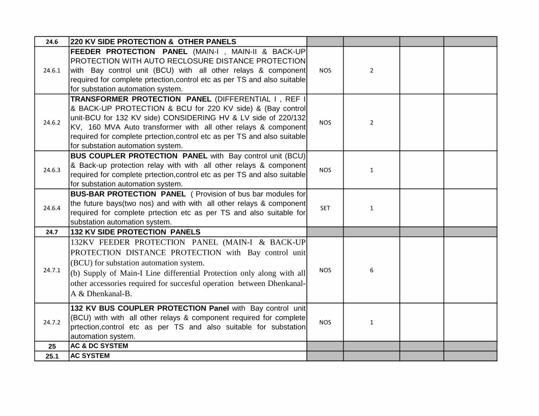
24.6 220 KV SIDE PROTECTION & OTHER PANELS
24.6.1
FEEDER PROTECTION PANEL (MAIN-I , MAIN-II & BACK-UP
PROTECTION WITH AUTO RECLOSURE DISTANCE
PROTECTION with Bay control unit (BCU) with all other relays &
component required for complete prtection,control etc as per TS
and also suitable for substation automation system.
NOS 2

24.6.2
TRANSFORMER PROTECTION PANEL (DIFFERENTIAL I , REF
I & BACK-UP PROTECTION & BCU for 220 KV side) & (Bay
control unit-BCU for 132 KV side) CONSIDERING HV & LV side of
220/132 KV, 160 MVA Auto transformer with all other relays &
component required for complete prtection,control etc as per TS
and also suitable for substation automation system.
NOS 2
24.6.3
BUS COUPLER PROTECTION PANEL with Bay control unit
(BCU) & Back-up protection relay with with all other relays &
component required for complete prtection,control etc as per TS
and also suitable for substation automation system.
NOS 1
24.6.4
BUS-BAR PROTECTION PANEL ( Provision of bus bar modules
for the future bays(two nos) and with with all other relays &
component required for complete prtection etc as per TS and also
suitable for substation automation system.
SET 1
24.7 132 KV SIDE PROTECTION PANELS
24.7.1
132KV FEEDER PROTECTION PANEL (MAIN-I & BACK-UP
PROTECTION DISTANCE PROTECTION with Bay control unit
(BCU) for substation automation system.
(b) Supply of Main-I Line differential Protection only along with all
other accessories required for succesful operation between
Dhenkanal-A & Dhenkanal-B .
NOS 6
24.7.2
132 KV BUS COUPLER PROTECTION Panel with Bay control
unit (BCU) with with all other relays & component required for
complete prtection,control etc as per TS and also suitable for
substation automation system.
NOS 1
25 AC & DC SYSTEM
25.1 AC SYSTEM
25.1.1
MAIN ACDB,(HAVING 800A, 50KA, DRAWOUT TYPE ACB WITH 3
O/C,E/F,U/V RELAYING FACILITY INDOOR TYPE AS PER
SPECIFICATION.(MAIN DB-1,MAIN DB-2 WITH B/C)
SET 1
25.1.2ACDB (HAVING 400A MCCB) AS PER SPECIFICATION (ACDB-1,
ACDB-2 WITH B/C)SET 1
25.1.3MAIN LIGHTING DISTRIBUTION BOARD (HAVING 250A MCCB AS
INCOMER)AS PER SPECIFICATION (WITH DB-1,DB-2 & B/C)SET 1
25.1.4INDOOR LIGHTING DISTRIBUTION BOARD AS PER SPECIFICATION.
(WITH DB-1,DB-2 & B/C)SET 1
25.1.5 EMERGENCY LIGHTING DISTRIBUTION BOARD SET 1
25.1.6 INDOOR RECEPTACLE BOARD SET 1
25.2 DC SYSTEM
25.2.1
220 V DC BOARD (HAVING 100A DC MCCB AS INCOMER, E/F
(EARTH LEAKAGE), UNDER & OVER VOLTAGE AS PER
SPECIFICATION (DC DB-1,DC DB-2 & B/C)
SET 1

25.2.2 220 V DC EMERGENCY DISTRIBUTION BOARD SET 1
26 BATTERY (350 AH PLANTE TYPE) FOR 220 V DC SET 2
27BATTERY CHARGER FOR 220 V, 350 AH PLANTE TYPE BATTERY
(FLOAT AND FLOAT CUM BOOST)SET 2
28 DISTILLED WATER PLANT OF 10 LTR/HR FOR BATTERY BANKS SET 1
29 WALKIE TALKIE SETSET
/PAIR 2
30
PORTABLE ALUMINIUM LADDER EXTENDABLE TYPE OF
ADEQUATE HEIGHT TO BE USED FOR MAINTENANCE OF
EQUIPMENT INSIDE SWITCH YARD.
NOS 2
31PEDESTAL MOUNTED WHEEL FITTED DERRICK FOR LIFTING/
LOWERING OF MATERIALS UP TO 1.5 TON CAPACITY.SET 1
32 WATER COOLER WITH WATER PURIFIER SYSTEM NOS 2
33
MAINTENANCE TESTING EQUIPMENT (AS PER ANNEXURE - I
,INDICATED IN TS-TIMK-SCHEDULE OF REQUIREMENTS OF
MAINTENANCE EQUIPMENT)
LOT 1
34
OTHER TOOLS AND PLANTS (T&P's) REQUIREMENT (AS PER
ANNEXURE - II ,INDICATED IN TS-TIMK-SCHEDULE OF REQUI-
REMENTS OTHER T&P's)
LOT 1
35
OFFICE FURNITURE (AS PER ANNEXURE - III ,INDICATED IN TS-
TIMK-SCHEDULE OF REQUIREMENTS OFFICE
FURNITURE)>PLACING IN CONTROL ROOM,CONFERENCE
ROOM,OFFICE ROOMS,LIBRARY,TESTING LAB,etc.
LOT 1
36
BEST QUALITY &APPROVED MAKE INSULATING MAT
(Confirming to IS:15652:2006) TO BE KEPT INFRONT OF ALL
PANELS,BOARDS ETC.(2000X1000X3)mm Size
NOS 50
37 EQUIPMENT and MATERIALS for GIS
37.1 ACCESSORIES
37.1.1SF6 Gas handling plant of adequate capacity as per the Technical
specification.SET 1
37.1.2SF6 gas service cart with all accessories as per the Technical
specification.SET 1
37.2 TESTING EQUIPMENT
37.2.1 GIS testing equipment as per the Technical specification. SET 1
38 ESSENTIAL TOOLS and SPARES for GIS
38.1 SPARES for 220KV GIS
38.1.1 Single phase voltage transformer SET 1
38.1.2 Single phase set of 5 cores current transformer including enclosure SET 1
38.1.3 Enclosure insulators and main circuit of busbar SET 1
38.1.4 Tripping and closing coils SET 3
38.1.5 SF6 Pressure gauges SET 2
38.1.6 SF6 Pressure relief devices SET 2
38.1.7 Auxiliary contacts for circuit breaker SET 1
38.1.8 Auxiliary contacts for DS and ES SET 1

38.1.9 SF6 gas in steel bottle 52 kg / bottle NOS 2
38.1.10 Spring charge motor for circuit breakers UNIT 1
38.1.11Complete drive mechanism for disconnect switches and grounding
switchesUNIT 1
38.1.12 Motor for disconnect switches and grounding switches UNIT 1
38.1.13 Complete drive mechanism for fast acting grounding switches UNIT 1
38.1.14 Motor for fast acting grounding switches UNIT 1
38.1.15 Rupture disc for circuit breakers / potential transformer NOS 1
38.1.16Set of spares for local control cabinet including M.C.B., fuses, time relays,
auxiliary relays and terminalsSET 1
38.1.17 Rupture disc for other compartments NOS 2
38.2 SPARES for 132KV GIS
38.2.1 Single phase voltage transformer SET 1
38.2.2 Single phase set of 5 cores current transformer including enclosure SET 1
38.2.3 Enclosure insulators and main circuit of busbar SET 1
38.2.4 Tripping and closing coils SET 3
38.2.5 SF6 Pressure gauges SET 2
38.2.6 SF6 Pressure relief devices SET 2
38.2.7 Auxiliary contacts for circuit breaker SET 1
38.2.8 Auxiliary contacts for DS and ES SET 1
38.2.9 Spring charge motor for circuit breakers UNIT 1
38.2.10Complete drive mechanism for disconnect switches and grounding
switchesUNIT 1
38.2.11 Motor for disconnect switches and grounding switches UNIT 1
38.2.12 Complete drive mechanism for fast acting grounding switches UNIT 1
38.2.13 Motor for fast acting grounding switches UNIT 1
38.2.14 Rupture disc for circuit breakers / potential transformer NOS 1
38.2.15Set of spares for local control cabinet including M.C.B., fuses, time relays,
auxiliary relays and terminalsSET 1
38.2.16 Rupture disc for other compartments NOS 2
38.3 SPECIAL TOOLS
38.3.1 SF6 gas leak detector as per the Technical specification. SET 1
38.3.2 SF6 gas analyzer as per the Technical specification. SET 1
38.3.3 Milli volt drop measurement applicance SET 1
38.3.4 One set of Box Spanner SET 1
38.3.5 One set of adjustable Spanner SET 1
38.3.6 SF6 gas bottle locking, measuring and filling assembly with all hose SET 2
38.3.7 One set of pipe grooving tools for the hydraulic operating mechanism SET 1
38.3.8 Infrared camera as per the Technical specification. SET 1
TOTAL OF SUBSTATION-SCHEDULE-1 -Plant (to Schedule No. 6 Grand Summary)
Name of Bidder:_______________________________
Signature of Bidder:_____________________________

Country of Origin Declaration Form
Item Description Code Country
2 Specify currency in accordance with specifications in Bid Data Sheet under ITB 19.1 in Single-Stage Bid, or ITB 34.1 in Two-Stage Bid. Create and use as many
columns for Unit Price and Total Price as there are currencies.
Name of Bidder:_______________________________
Signature of Bidder:_____________________________
1 Bidders shall enter a code representing the country of origin of all imported plant and equipment.

(1) (2) (1) x (2)
1
3150A, 50kA for 3s, Double Busbar Circuit Breaker (Circuit
breaker shall be E2-C2-M2 class as per IEC 62271-100)
arrangement.245kV OUTDOOR GIS EQUIPMENT as per
latest IEC standard & type tested equipment as per
technical specification, with open future proof & flexible
system in line with IEC 61850 & IEC 62271-203.
SUPPLY OF FOLLOWING EQUIPMENTS
(As per Technical Specification)UNIT
Qu
an
tity
fo
r: C
on
str
ucti
on
of
2x160
MV
A A
uto
Tra
nsfo
rmer,
220/1
32 G
IS
S/S
at
(Gu
nd
ich
ap
ad
a)
Dh
en
kan
al O
ut
Do
or
typ
e G
IS S
/S (
New
)
Unit Price1
Total Price1
ODISHA POWER TRANSMISSION CORPORATION LIMITEDNAME OF THE WORK:-Design, Supply and Installation of 2X160MVA Auto Transformer ,220/132 KV Out Door Type GIS Grid Sub-
station at (Gundichapada),Dhenkanal and 2 nos. 132KV Feeder bay extension at existing 132/33KV Dhenkanal grid sub-station
for connectivity with Dhenkanal GIS in Odisha State of India under PACKAGE-1 Under Japan International Cooperation Agency
(JICA)’s ODA Loan.
Loan Agreement No: [ID-P245] - FB No: [CPC/JICA/ICB/01/18-19]- Reference Identification No: [OPTCL/JICA/PKG-1]
Schedule No. 2. Plant Supplied from Within the Employer’s Country (Sub-station )
NAME OF THE BIDDER
SL. NO.

1.1
245kV, 3150A, 50kA for 3 sec (Busbar, CB, Disconnector,
Grounding Switch & CT), SF6 gas insulated Transformer
Feeder Bay Module each comprising of SF6 gas insulated
Single Pole Circuit Breaker (1 Set), Single Phase Current
Transformer (6 Nos), Motorised Busbar 3 Phase Disconnector (2
Nos), Motorised Disconnector (1 No), Motorised safety
Grounding switch (3 Nos), Local Control Cubicle, SF6 gas
monitoring system for complete bay, SF6 bus duct termination
arrangement (3 Nos), PD sensor (adequate number of UHF
sensors in the offered GIS equipment for detection of Partial
discharge (of 5 pC and above) as per IEC 60270 through Partial
Discharge (PD) monitoring system), different gas compartment,
O-ring & gaskets, Nuts, Bolts & Washers for Outdoor use,
Absorbent, Limit Switch, SF6 Gas, etc. to complete ICT Feeder
Bay Module & its earthing arrangement with earthing strips of
adequate size (as per IEEE Std 80-2013 to protect operating
staff against any hazardous touch voltages and electro-magnetic
interferences) as per the technical specification(Price of the
equipment has been converted from Japanese Yen to INR as
per the selling rate on Dt.18.12.2018)
Set 2

1.2
245kV, 3150A, 50kA for 3 sec (Busbar, CB, Disconnector,
Grounding switch, CT & PT), SF6 gas insulated Line Feeder
Bay Module each comprising of SF6 gas insulated Single Pole
Circuit Breaker (1 Set), Single Phase Current Transformer (6
Nos), Single phase Line Potential Transformer (4 winding) (3
Nos), Motorised 3 Phase Busbar Disconnector (2 Nos),
Motorised safety Grounding switch (2 Nos), Motorised 3 Phase
Disconnector with high speed fault making Motorised Grounding
switch (1 No), Local Control Cubicle, SF6 gas monitoring system
for complete bay, SF6 bus duct termination arrangement (3
Nos), PD sensor (adequate number of UHF sensors in the
offered GIS equipment for detection of Partial discharge (of 5 pC
and above) as per IEC 60270 through Partial Discharge (PD)
monitoring system), different gas compartment, O-ring &
gaskets, Nuts, Bolts & Washers for Outdoor use, Absorbent,
Limit Switch, SF6 Gas, etc. to complete Line Feeder Bay Module
& its earthing arrangement with earthing strips of adequate size
(as per IEEE Std 80-2013 to protect operating staff against any
hazardous touch voltages and electro-magnetic interferences)
as per the technical specification.
Set 4
1.3
245kV, 3150A, 50kA for 3 sec (Busbars, Disconnector,
Grounding switch & bus PT), 1 Phase Isolated Bus-PT Bay
Module comprisig of SF6 gas insulated metal enclosed busbars
each enclosed in bus enclosures running along the length of the
switchgear to interconnect each of circuit breaker bay module.
Each busbar set shall be complete with Single phase bus
Potential Transformer (4 winding) (3 Nos), Motorised 3 Phase
Disconnector (1 No) , Motorised Busbar safety Grounding switch
(1 No), Local Control Cubicle, SF6 gas monitoring system PD
sensor (adequate number of UHF sensors in the offered GIS
equipment for detection of Partial discharge (of 5 pC and above)
as per IEC 60270 through Partial Discharge (PD) monitoring
system), different gas compartment, O-ring & gaskets, Nuts,
Bolts & Washers for Outdoor use, Absorbent, Limit Switch, SF6
Gas, etc. to complete the bus & its earthing arrangement with
earthing strips of adequate size (as per IEEE Std 80-2013 to
protect operating staff against any hazardous touch voltages
and electro-magnetic interferences) as per the technical
specification.
Set 1

1.4
245kV, 3150A, 50kA for 3 sec (CB, Disconnector, Grounding
switch & CT), SF6 gas insulated Bus Coupler Bay Module
comprising of SF6 gas insulated Single Pole Circuit Breaker (1
Set), Single Phase Current Transformer (6 Nos), Motorised 3
Phase Disconnector (2 Nos), Motorised safety Grounding switch
(2 Nos), Local Control Cubicle, SF6 gas monitoring system, PD
sensor (adequate number of UHF sensors in the offered GIS
equipment for detection of Partial discharge (of 5 pC and above)
as per IEC 60270 through Partial Discharge (PD) monitoring
system), different gas compartment, O-ring & gaskets, Nuts,
Bolts & Washers for Outdoor use, Absorbent, Limit Switch, SF6
Gas, etc. to complete Bus Coupler Bay Module & its earthing
arrangement with earthing strips of adequate size (as per IEEE
Std 80-2013 to protect operating staff against any hazardous
touch voltages and electro-magnetic interferences) as per the
technical specification.
Set 1
1.5
245kV, 3150A, 50 kA, 3 sec, single phase, SF6 gas Insulated
Bus Duct outside GIS Bay along with associated Support
structure arrangement bends, joints,accessories, & its earthing
arrangement with earthing strips of adequate size (as per IEEE
Std 80-2013 to protect operating staff against any hazardous
touch voltages and electro-magnetic interferences) as per the
technical specification.
RM 700
1.6
245kV, 3150A, 50kA SF6/Air BUSHING (Bushing shall be of
Polymer / composite insulator type and shall be seamless
sheath of a silicone rubber compound. The hollow silicone
composite insulators shall comply as per IEC 61462 and IEC
62217. The design of the composite insulators shall be tested
and verified according to IEC 61462) FOR CONNECTING GIS
TO AIS along with support structure.
No. 18

1.7
Portable Partial Discharge Monitoring System (PDM):
245kV system shall have Portable Partial Discharge Monitoring
System (PDM) & shall be capable for measuring PD in charged
GIS environment, bandwidth in order of 100MHz–2GHz &
provision to select a wide range of intermediate bandwidths and
the principle of operation shall be based on UHF principle of
detection. The Detection and measurement of PD and bouncing
particles having in built large coloured LCD for displaying and
storing facility in the instrument for further analysis to locate
actual source of PD such as free conducting particles, floating
components, voids in spacers, particle on spacer surfaces etc.
Set 1
2
2000A, 40kA for 3s, Double Busbar Circuit Breaker (Circuit
breaker shall be E2-C2-M2 class as per IEC 62271-100)
arrangement.
145kV OUTDOOR GIS EQUIPMENT as per latest IEC
standard & type tested equipment as per technical
specification, with open future proof & flexible system in
line with IEC 61850 & IEC 62271-203.

2.1
145kV, 2000A, 40kA for 3 sec (Busbar, CB, Disconnector,
Grounding Switch & CT), SF6 gas insulated Transformer Feeder
Bay Module each comprising of SF6 gas insulated Single Pole
Circuit Breaker (1 Set), Single Phase Current Transformer (6
Nos), Motorised Busbar 3 Phase Disconnector (2 Nos),
Motorised Disconnector (1 No), Motorised safety Grounding
switch (3 Nos), Local Control Cubicle, SF6 gas monitoring
system for complete bay, SF6 bus duct termination arrangement
(3 Nos), PD sensor (adequate number of UHF sensors in the
offered GIS equipment for detection of Partial discharge (of 5 pC
and above) as per IEC 60270 through Partial Discharge (PD)
monitoring system), different gas compartment, O-ring &
gaskets, Nuts, Bolts & Washers for Outdoor use, Absorbent,
Limit Switch, SF6 Gas, etc. to complete ICT Feeder Bay Module
& its earthing arrangement with earthing strips of adequate size
(as per IEEE Std 80-2013 to protect operating staff against any
hazardous touch voltages and electro-magnetic interferences)
as per the technical specification.
Set 2
2.2
145kV, 2000A, 40kA for 3 sec (Busbar, CB, Disconnector,
Grounding switch, CT & PT), SF6 gas insulated Line Feeder Bay
Module each comprising of SF6 gas insulated Single Pole Circuit
Breaker (1 Set), Single Phase Current Transformer (6 Nos),
Single phase Line Potential Transformer (4 winding) (3 Nos),
Motorised 3 Phase Busbar Disconnector (2 Nos), Motorised
safety Grounding switch (2 Nos), Motorised 3 Phase
Disconnector with high speed fault making Motorised Grounding
switch (1 No), Local Control Cubicle, SF6 gas monitoring system
for complete bay, SF6 bus duct termination arrangement (3
Nos), PD sensor (adequate number of UHF sensors in the
offered GIS equipment for detection of Partial discharge (of 5 pC
and above) as per IEC 60270 through Partial Discharge (PD)
monitoring system), different gas compartment, O-ring &
gaskets, Nuts, Bolts & Washers for Outdoor use, Absorbent,
Limit Switch, SF6 Gas, etc. to complete Line Feeder Bay Module
& its earthing arrangement with earthing strips of adequate size
(as per IEEE Std 80-2013 to protect operating staff against any
hazardous touch voltages and electro-magnetic interferences)
as per the technical specification.
Set 2

2.3
145kV, 2000A, 40kA for 3 sec (Busbars, Disconnector,
Grounding switch & bus PT), 1 Phase Isolated Bus-PT Bay
Module comprisig of SF6 gas insulated metal enclosed busbars
each enclosed in bus enclosures running along the length of the
switchgear to interconnect each of circuit breaker bay module.
Each busbar set shall be complete with Single phase bus
Potential Transformer (4 winding) (3 Nos), Motorised 3 Phase
Disconnector (1 No) , Motorised Busbar safety Grounding switch
(1 No), Local Control Cubicle, SF6 gas monitoring system PD
sensor (adequate number of UHF sensors in the offered GIS
equipment for detection of Partial discharge (of 5 pC and above)
as per IEC 60270 through Partial Discharge (PD) monitoring
system), different gas compartment, O-ring & gaskets, Nuts,
Bolts & Washers for Outdoor use, Absorbent, Limit Switch, SF6
Gas, etc. to complete the bus & its earthing arrangement with
earthing strips of adequate size (as per IEEE Std 80-2013 to
protect operating staff against any hazardous touch voltages
and electro-magnetic interferences) as per the technical
specification.
Set 1

2.4
145kV, 2000A, 40kA for 3 sec (CB, Disconnector, Grounding
switch & CT), SF6 gas insulated Bus Coupler Bay Module
comprising of SF6 gas insulated Single Pole Circuit Breaker (1
Set), Single Phase Current Transformer (6 Nos), Motorised 3
Phase Disconnector (2 Nos), Motorised safety Grounding switch
(2 Nos), Local Control Cubicle, SF6 gas monitoring system, PD
sensor (adequate number of UHF sensors in the offered GIS
equipment for detection of Partial discharge (of 5 pC and above)
as per IEC 60270 through Partial Discharge (PD) monitoring
system), different gas compartment, O-ring & gaskets, Nuts,
Bolts & Washers for Outdoor use, Absorbent, Limit Switch, SF6
Gas, etc. to complete Bus Coupler Bay Module & its earthing
arrangement with earthing strips of adequate size (as per IEEE
Std 80-2013 to protect operating staff against any hazardous
touch voltages and electro-magnetic interferences) as per the
technical specification.
Set 1
2.5
Portable Partial Discharge Monitoring System (PDM):
145kV system shall have Portable Partial Discharge Monitoring
System (PDM) & shall be capable for measuring PD in charged
GIS environment, bandwidth in order of 100MHz–2GHz &
provision to select a wide range of intermediate bandwidths and
the principle of operation shall be based on UHF principle of
detection. The Detection and measurement of PD and bouncing
particles having in built large coloured LCD for displaying and
storing facility in the instrument for further analysis to locate
actual source of PD such as free conducting particles, floating
components, voids in spacers, particle on spacer surfaces etc.
Set 1
3 245 KV,2000A,40KA,ISOLATORS
3.1 245 KV, 2000A, 40KA, Center break ISOLATORS WITH EARTH SWITCH NOS 4
4 216 KV, METAL OXIDE SURGE ARRESTOR,10 KA, class III NOS 18
5 220 KV Bus Post Insulators NOS 6
6 145 KV,1250A,31.5KA,ISOLATORS

6.1 145 KV, 2000A, 40KA, Center break ISOLATORS WITH EARTH SWITCH NOS 2
7 120 KV METAL OXIDE SURGE ARRESTOR, 10 KA, Class III NOS 12
830 KV, METAL OXIDE SURGE ARRESTOR, 10kA, Class II (AIS) as per technical
specification.NOS 9
9 BUS BAR & CIRCUIT MATERIALS
9.1 LONG ROD ANTI FOG PORCELAIN INSULATORS
9.1.1 120 KN INSULATOR NOS 249.1.2 90 KN INSULATOR NOS 6
9.2 ACSR MOOSE CONDUCTOR KMS 3.2
10 HARDWARES & FITTINGS/SPACERS/CLAMP & CONNECTORS
10.1 220 KV Single Suspension(120 KN)H/W fitting for Twin Moose ACSR NOS 12
10.2 132 KV Single Suspension(90KN) H/W fitting for single Moose ACSR NOS 6
10.3 T- clamp for ACSR ZEBRA run to ACSR MOOSE drop NOS 36
10.4 T- clamp for ACSR PANTHER run to ACSR MOOSE drop NOS 18
10.5 220 KV PI clamp NOS 6
10.6 Spacer for Moose ACSR NOS 36
10.7 220 KV Isolator pad clamp NOS 12
10.8 220 KV LA Clamp NOS 18
10.9 132 KV Isolator pad clamp NOS 6
10.10 132 KV LA Clamp NOS 12
10.11 PG Clamp for ACSR Moose NOS 108
11
XLPE Power Copper conductor cable for the GIS system (for 132
KV connectivity from GIS equipment to Auto Transformer &
Gantry of Existing 132/33KV S/S)
11.1132KV XLPE Copper Cable 1000 sq. mm Single Core (from 132 KV
GIS to 132KV Gantry)Mtrs 3000
11.2132KV Cable termination kits (Outdoor GIS side) suitable for 1CX
1000 sq. mm Copper CableNOS 12
11.3132 KV Cable termination kit including Cable to Air Bushing suitable for
outdoor for 132 KV Feeders & Transformers suitable for 1CX1000 Sqmm copper
cable.
NOS 12
11.4EHV cable accessories like, link box, SVL, bonding cables, earthing
cable for 132 kV system as per tech specification.LOT 1
11.533KV XLPE Copper Cable 300 sq. mm Single Core (For connectivity
to Station Transformer)Mtrs 1000

11.633 KV Cable termination kit including Cable to Air Bushing suitable for outdoor
for 33 KV suitable for 1CX300 Sqmm copper cable.NOS 12
12 EARTH WIRES & IT'S HARDWARES & FITTING
12.1 Earthing Spikes of 9 mtr long each and Its Fittings in all respect. (220 kv side) NOS 5
12.2Earthing Spikes of 7 mtr long each and Its Fittings in all respect. (132 kv side)
NOS 3
13 SUBSTATION EARTHING SYSTEMS
13.1EARTHING CONDUCTOR FOR BURRIAL : 75X10 mm GI Flat for laying
(spacing maximum 5m both way ) MT 48.000
13.2EARTHING CONDUCTOR: 50X6 mm GI Flat for Raiser from the burial earth
mat to equipment,structure etc)MT 4.000
13.3EARTHING DEVICE & ASSOCIATED ACCESSORIES (50 mm heavy duty GI
PERFORATED PIPE 3 mtrs long for treated earth pit)Nos. 50
13.4EARTHING DEVICE & ASSOCIATED ACCESSORIES 40mm MS rod 3 mtrs
long for non treated earth pit)Nos. 120
14G.I Cable Trays including support GI angle suitable for different sections i.e.
Section:1-1,2-2,3-3 & 4-4 along with its accessories as per TS.
14.1 G.I Cable Trays(size: 450x75x2500mm) MTRS 2000
14.2 G.I Cable Trays(size: 300x75x2500mm) MTRS 2500
14.3 G.I Cable Trays(size: 150x75x2500mm) MTRS 2000
14.4 Support G. I angle 50x50x6 mm for cable tray MT 4
15SUB STATION SWITCYARD BMK,AC CONSOLE & OTHER MARSHALLING
BOXES
15.1BAY MARSHALLING KIOSK (02 Nos. in 220 KV Bay,01 Nos. in 132 KV Bay
BAY )NOS 3
15.2SWITCH YARD AC CONSOLE FOR LIGHTING (01 Nos. in 220 KV bay, 01
No. in 132 kv Bay )NOS 2
15.3SWITCH YARD RECEPTACLE BOARD FOR TFR OIL FILTERATION (01
No. near each 220/132 Auto Transformers)NOS 2
15.4SWITCH YARD RECEPTACLE BOARD FOR WELDING & OTHER
EMERGENCY (01 No.) NOS 1
17
SWITCH YARD STRUCTURES (LATTICE TYPE FOR COLUMN & BEAMS)
FOR 220KV, 132KV & 33 KV CLASS INCLUDING FOUNDATION BOLTS &
NUTS.
17.1 DIFFERENT TYPES OF COLUMNS WITH DETAILS
17.1.1 P1S-220 KV (NOMINAL UNIT WT- 4.5 MT)- 5 NOS) MT 22.500
17.1.2 T1S 132KV (NOMINAL UNIT WT-1.2MT (3 NOS.) MT 3.600

17.2 DIFFERENT TYPE OF BEAMS WITH DETAILS
17.2.1 Q1-220KV (NOMINAL UNIT WT- 1.5 MT) (4 NOS.) MT 6.000
17.2.2 G1 - 132KV (NOMINAL UNIT WT-0.62MT) ( NOS) MT 1.240
17.3 TOTAL WEIGHT OF COLUMN & BEAMS MT 33.340
17.4
EQUIPMENT SUPPORT STRUCTURES (LATTICE TYPE) FOR ALL 220KV
& 132 KV EQUIPMENTS INCLUDING FOUNDATION BOLTS & NUTS
17.4.1 ISOLATORS-220KV ( SI with E/S 4 Nos.) MT 5.084
17.4.2 ISOLATORS-132KV ( SI with E/S-2 Nos.) MT 1.318
17.4.3 CVTS-220 KV (12 Nos.) MT 2.652
17.4.4 CVTS-132 KV (6 Nos ) MT 1.344
17.4.5 Surge Arrester-220 KV( 18 Nos.) MT 5.258
17.4.6 Surge Arrester-132 KV( 12 Nos.) MT 3.288
17.4.7 BPI-220 KV (6Nos.) MT 13.469
17.4.8 Cable Termination Port -132 KV (24Nos) MT 8.400
17.5 TOTAL WEIGHT OF EQUIPMENT STRUCTURES MT 40.812
17.6Total weight of GI Nuts and Bolts for Columns, Beams & Equipment
Structures MT 2.041
18 GENERAL EQUIPMENT & SUBSTATION ACCESSORIES
18.1POWER CABLES,1.1KV,XLPE & PVC ARMOURED, ALUMINIUM
CONDUCTOR (As per Specification)
18.1.1 XLPE 3.5 CX185 mm2 MTR 500
18.1.2 XLPE 3.5 CX120 mm2 MTR 500
18.1.3 PVC 3.5 CX70 mm2 MTR 300
18.1.4 PVC 3.5 CX35 mm2 MTR 500
18.1.5 PVC 4 CX 16 mm2 MTR 1000
18.1.6 PVC 4CX 6 mm2 MTR 1000
18.1.7 PVC 2CX 6 mm2 MTR 2000
18.2CONTROL CABLES,1.1 KV, PVC,STRANDED COPPER(As per
specification)
18.2.1 4 CX 2.5 mm2 MTR 6000
18.2.2 5 CX 2.5 mm2 MTR 4000
18.2.3 7CX 2.5 mm2 MTR 5000
18.2.4 10 CX 2.5 mm2 MTR 10000
18.2.5 12 CX 2.5 mm2 MTR 5000

18.2.6 16 CX 2.5 mm2 MTR 2000
18.2.7 19 CX 2.5 mm2 MTR 2000
18.2.8 1CX 120 mm2 BAT TO BAT CHARGER & CHARGER TO DCDB MTR 300
19 ACCESSORIES FOR PLCC SYSTEM With OPGW cable
19.1 48 Fibre Optic Approach cable along with HDPE Pipes KM 0.50
19.2 Optical line Terminal Equipment(OLTE) -STM4 type SDH equipment with
integrated MUX & tributary cards for speech & data ports for interfacing of
Speech & data which should be compatible with existing OPTCL system
No
1
19.3 Digital Teleprotection Equipment and accessories to be suitable for interfacing
with SDHMUX
No1
19.4 Supply of FODP(Fibre Optic Distribution Panel)48 F: Indoor type,rack
mounted with FCPC coupling and pig tails(DWSm Fibre)
No1
19.5 48 V, 300 AH, maintenance free VRLA Battery set. Set 1
19.6 SMPS based Battery Charger of 75A suitable for 48V VRLA Battery set No 1
19.7 2.5 sq. mm muti strand 2 core control cable(power supply,Transducer/MFT PT
supply)Metre 300
19.8 2.5 sq. mm multi strand 4 core control cable(Transducer/MFT CT supply) Metre 300
19.9 1.5 sq. mm multi strand 10 core control cable(Digital Input) Metre 200
19.10 10 sq. mm 2 core multi strand control cable(Battery) Metre 100
19.11 48V DCDB Set 1
19.12 Earth Flat, Cable Tray, Telephone cable, Foundation rail, Junction Box,. Lot 1
20 SUPPLY OF POWER TRANSFORMER,STATION TRANSFORMER &
OTHER MATERIALS FOR MEETING THE AUXILIARY SUPPLY OF THE
SUB-STATION AS PER TECHNICAL SPECIFICATION20.1 AUTO TRANSFORMER: 220/132KV,160 MVA (inclusive of all costs
towards type test charges, Mandatory spares, Spanners & Special tools,
accessories, etc as specified in the Technical specification)
NOS 2
20.2STATION TRANSFORMER 33KV/0.43 V,500 KVA (Confirming to
Energy Efficiency Level 2 -AS PER SPECIFICATION & relevant IS)NOS 2

20.3 One no. 4 pole structure (HDG Type) alongwith other equipment
& materials for two nos station transformers:
1.4 Pole structure (using 200X100 mm RS Joist)
2. Channel & Angle FOR BRACING OF, CHANNEL for the SA &
Isolator & HG fuse etc.
3. 90 KN Disc/composite long rod Insulators for 33 KV (48 nos./12
sets) for bus, Bus stringing using ACSR moose conductor & tension
hardwares,other clamps & connectors etc as per requirement.
4. 2sets of 33 KV Isolator (800 AMP) for 33 KV side of station trafo.
5. 2sets of 33 KV HG FUSE.
6. 100 Sq mm AAAC conductor suitable for connection between HG
fuse & station transformer bushing.
7. 2 sets of LT OUT DOOR KIOSK MADE OUT OF 3mm CRCA sheet
Gl MARSHALLING BOX suitable for outdoor mounting. The bus bar
suitable for 1000 AMP shall be arranged in the out door kiosk and
other Facility like two sets of 400 Amps MCCB for incoming &
outgoing with required sizes of terminal studs for power cable
termination & any other accessories required.
AII materials shall be As per relevant latest IS & as per the direction of
Engg. in charge
SETS 2
21 SUBSTATION LIGHTING (AS PER SPECIFICATION AND APPROVED
DRAWINGS) (Switch yard and other street area)
21.1
SUB-STATION SWITCH YARD LIGHTING : IT INCLUDES SUPPLY
OF FIXTURES & LAMPS (LED) of reputed make
(Philips/CGL/Bajaj/other approved make of OPTCL) with switch
gear,GI Conduit etc.(Lighting fixtures are to be fixed rigidly on the
Column at a suitable height so that the required lux can be
achieved).(150 watt each). (* REMARKS : FOR SUPPLY OF ALL THE
CABLES AS INDICATED ARE COVERED IN THE CABLE ITEMS AS
INDICATED ABOVE )
SET 60

21.2
STREET LIGHTING: GI Tubular Pole: (410-SP-24: IS 2713-Part-II-
1980 or latest) Length of pole 8.5 mtrs(minimum weight 158 Kgs). &
LED light fittings etc.
(ALL THE STREET LIGHT POLE SHALL BE OF GI TUBULAR POLE
AND PROVISION OF A GI JUNCTION BOX WITH SUITABLE
COVERS AT A HEIGHT OF 1 METRE FROM THE GROUND. THE
JUNCTION BOX SHALL HAVE PROVISION OF FUSES, BUSES,
CONNECTORS FOR CABLE IN AND OUT. ( IT INCLUDES SUPPLY
OF LED LIGHTING FIXTURES WITH LAMPS of 100 Watts of
reputed make (Philips/CGL/Bajaj/other approved make of OPTCL) &
as per technical specification. (* REMARKS : FOR SUPPLY OF ALL
THE CABLES AS INDICATED ARE COVERED IN THE CABLE
ITEMS AS INDICATED ABOVE )
SET 25
21.3
OUTDOOR KIOSK (HDG type) FOR STREET LIGHTING PURPOSE
HAVING 2 NOS 200 AMP SWITCH FUSE UNITS AND , 6 NOS.OUT
LETS OF 32 AMP MCB FOR STREET LIGHTING. (SUITABLE FOR
XLPE CABLES(3.5 CORE 120 SQMM) FROM MAIN ACDB FROM
CONTROL ROOM TO THE OUT DOOR KIOSK. XLPE CABLE OF 4C
X 16 SQMM FROM OUTDOOR KIOSK TO THE STREET LIGHT
POLES AND 4CX6 SQMM FROM POLE TO POLE AND 2CX6 SQMM
FROM POLE TO LIGHTING FIXTURES. > 1 NO. OUTDOOR KIOSK
FOR COLONY SUPPLY PURPOSE HAVING (* REMARKS : FOR
SUPPLY OF ALL THE CABLES AS INDICATED ARE COVERED IN
THE CABLE ITEMS AS INDICATED ABOVE )
SET 2
21.4
40 Mtrs heigh Monopole (HDG) Lighting cum Lightning Mast including
LED lighting fixtures (240 watts each minimum 8 Nos.) with control
gear panel etc suitable for wind zone-V , with all other accessories like
motor for hoisting/lowering the lighting platform & other switchgear
and lighting control panel including required cable(copper) & other
accessories etc.
SET 2
21.5
INDOOR LIGHTING (AS PER SPECIFICATION AND APPROVED
DRAWINGS ) ( Control room building,Store shed,store room,Security
room cum Visitors room and other area)

21.5.1
CONTROL ROOM BUILDING INDOOR LIGHTING, IT INCLUDES SUPPLY
OF FIXTURES & LAMPS (LED) of reputed make (Philips/CGL/Bajaj/ other
approved make of OPTCL) with switch gear,Conduit & other required
materials for succesful illumination of the area/rooms.( No. of LED Lighting
fixtures are to be calculated based on the illumination design considering the
required lux level indicated in the technical spec & fixing of the same rigidly on
the suitable height either ceiling & wall as required.)
LOT 1
21.5.2
INDOOR LIGHTING OF SECURITY SHED CUM VISITORS ROOM,PUMP
HOUSE,STORE SHED,STORE ROOM, FFPH BUILDING: IT INCLUDES
SUPPLY OF FIXTURES & LAMPS (LED) of reputed make (Philips/CGL/Bajaj/
other approved make of OPTCL) with switch gear,Conduit & other required
materials for succesful illumination of the area/rooms.( No. of LED Lighting
fixtures are to be calculated based on the illumination design considering the
required lux level indicated in the technical spec & fixing of the same rigidly on
the suitable height either ceiling & wall as required.)
LOT 1
21.6
2 TR CAPACITY SPLIT AIR CONDITIONING UNITS WITH REMOTE
CONTROL FACILITY: INCLUDING SUPPLY OF 5 star rated AIR
CONDITIONERS, Automatic Voltage Stabiliser,CONTROL BOXES ETC FOR
COMPLETING THE A.C SCHEME.(AS PER SPECIFICATION ) FOR
CONTROL ROOM, CARRIER ROOM & CONFERENCE ROOM.,OFFICE
ROOM etc which includes all type of cables & wires and a main control switch
gear kiosk having sufficient outlet for each air conditioner unit.
SET 20

22
Supply of Smoke & Heat detection system: Addressable optical
Smoke & Heat Multi detector (adequate Nos) for control room
building including all accessories, the Main control panel
(Microprocessor based 2 loop fire alarm control panel expandable upto
18 loops fully networkable with each loop capable of taking 99
devices, 8 line x 40 character alpha- numeric liquid crystal display .The
panel shall be soft addressable type . The panel shall be able to give
pin point location of all fire/fault conditions. Further, the panel must be
able to automatically switch off respective control switches when ever
any alarm is triggered. The panel shall have in built rectifier, Loop
cards,provision for externel & internal printer(if required), L C D unit to
indicate Fire/Fault Signal with address and analog output, built in
printer to log all fire or fault events complete in all respects, integral
SMF lead acid batteries with sealed cells of 24 V capable of running
for a minimum of 8 hours with integral battery charger complete as
required and as per specification. The fire alarm panel shall be
suitable for software integration with BMS & PA system ,wall mounting
loop powered addressable type hooter with all accessories ,
addressable manual call box made of polycarbonate with plastic break
glass front and complete with monitor module MCB, addressable
isolator module with required PVC box, fittings and fixtures, wiring with
PVC FRLS wire to cover the required for fire & smoke detection etc.
(One control room building is to be provided with Heat & smoke
detection). Should have facility for integration with SAS.
SET 1
23
FIRE FIGHTING SYSTEM(PORTABLE AND WHEEL MOUNTED SETS FOR
CONTROL ROOM,EQUIPMENT LIKE TRANSFORMER AND OTHER
AREAS AS PER TECH SPEC(REFER TS-INST TO BIDDER BEFORE
DESIGN-SL NO 16-ANNEXURE - I)
23.1 FOAM TYPE-9 LTRS NOS 5
23.2 DRY CHEMICAL POWDER(TROLLEY MOUNTED)- 22.5 KGS NOS 6
23.3 DRY POWDER TYPE - 5 KGS NOS 6
23.4 CO2 - 4.5 KGS NOS 6
23.5 CO2 - 9 KGS NOS 6
23.6 CO2 (TROLLY MOUNTED)- 22.5 KGS NOS 4

23.7 9 litre Water type Nos. 4
23.8 50 Litres Mechanical Foam type Nos. 2
23.9 FIRE BUCKET (6 NOS IN EACH STAND) WITH STAND SET 5
24
SUBSTATION AUTOMATION SYSTEM FOR 220/132 KV
SUBSTATION ON PRP MODE: Design , engineering , drawing,
supervision, installation , testing & commissioning of Substation
Automation system alongwith Supply of the following 220 and 132 kV
level of protection panels consisting of Bay control Units & numerical
protection relays and other auxiliary relays suitable for SAS as per
technical specification.
(220KV side: COMPRISING OF 04 Nos. FEEDER BAYS + 02
TRANSFORMER BAYS + 01 Nos BUS COUPLER BAY & 132 KV
side: COMPRISING OF 02 Nos. FEEDER SAYS + 02 Nos
TRANSFORMER BAYS + 01 No. BUS COUPLER BAY)
NOTE: All protective relays & BCU shall be numerical type.
24.1Yard AC Kiosk :5000 mm (L)x4000mm (W)x 3300mm (H) with AC, as per the
Specification; Nos. 3
24.2
Gate way panel for Sub-Station Automation (in PRP as per the
specification & indicative drg ) system (for All 220 & 132 KV side bays
including the future bays),other accessories (comprising servers,
engg. Station, works station (Main & standby), Remote station control,
Colour Laser jet Printers & dot matrix printer for local station as per
requirement and also for remote station, Ethernet Switches , LIU, Red
Box, Multimode glass fibre Doublle jacket armoured optical cables,
special cables like F.O patch cord & armoured FO cables of adequate
length etc required for the system in all respect as per latest IEC
61850 standard, Inverters of required capacity & rating (3KVA-Input
shall be both A.C & D.C and output shall be A.C) etc as per TS. A
Full HD LED screen of 70 inches for display,SAS furnitures of Godrej
make & including all type of accessories & as per technical
specification.
SET 1
24.3
BCU for Substation Auxilliary System (Datas for monitoring of
Station AC, Station DC, Lighting, Fire fighting, Air conditioning, Diesel
generator etc. as per the site requirement)
SET 1
24.5 GPS System with PTP, IRIG-B, SNTP SET 1
24.6 220 KV SIDE PROTECTION & OTHER PANELS
24.6.1
FEEDER PROTECTION PANEL (MAIN-I , MAIN-II & BACK-UP
PROTECTION WITH AUTO RECLOSURE DISTANCE PROTECTION
with Bay control unit (BCU) with all other relays & component
required for complete prtection,control etc as per TS and also suitable
for substation automation system.
NOS 2
24.6.2
TRANSFORMER PROTECTION PANEL (DIFFERENTIAL I , REF I
& BACK-UP PROTECTION & BCU for 220 KV side) & (Bay control
unit-BCU for 132 KV side) CONSIDERING HV & LV side of 220/132
KV, 160 MVA Auto transformer with all other relays & component
required for complete prtection,control etc as per TS and also suitable
for substation automation system.
NOS 2
24.6.3
BUS COUPLER PROTECTION PANEL with Bay control unit (BCU)
& Back-up protection relay with with all other relays & component
required for complete prtection,control etc as per TS and also suitable
for substation automation system.
NOS 1
24.6.4
BUS-BAR PROTECTION PANEL ( Provision of bus bar modules for
the future bays(two nos) and with with all other relays & component
required for complete prtection etc as per TS and also suitable for
substation automation system.
SET 1
24.7 132 KV SIDE PROTECTION PANELS
24.7.1
132KV FEEDER PROTECTION PANEL (MAIN-I & BACK-UP
PROTECTION DISTANCE PROTECTION with Bay control unit
(BCU) for substation automation system.
(b) Supply of Main-I Line differential Protection only along with all
other accessories required for succesful operation between Dhenkanal-
A & Dhenkanal-B.
NOS 6
24.7.2
132 KV BUS COUPLER PROTECTION Panel with Bay control unit
(BCU) with with all other relays & component required for complete
prtection,control etc as per TS and also suitable for substation
automation system.
NOS 1
25 AC & DC SYSTEM
25.1 AC SYSTEM

25.1.1
MAIN ACDB,(HAVING 800A, 50KA, DRAWOUT TYPE ACB WITH 3
O/C,E/F,U/V RELAYING FACILITY INDOOR TYPE AS PER
SPECIFICATION.(MAIN DB-1,MAIN DB-2 WITH B/C)
SET 1
25.1.2ACDB (HAVING 400A MCCB) AS PER SPECIFICATION (ACDB-1, ACDB-2
WITH B/C)SET 1
25.1.3MAIN LIGHTING DISTRIBUTION BOARD (HAVING 250A MCCB AS
INCOMER)AS PER SPECIFICATION (WITH DB-1,DB-2 & B/C)SET 1
25.1.4INDOOR LIGHTING DISTRIBUTION BOARD AS PER SPECIFICATION.
(WITH DB-1,DB-2 & B/C)SET 1
25.1.5 EMERGENCY LIGHTING DISTRIBUTION BOARD SET 1
25.1.6 INDOOR RECEPTACLE BOARD SET 1
25.2 DC SYSTEM
25.2.1 220 V DC BOARD (HAVING 100A DC MCCB AS INCOMER, E/F (EARTH SET 1
25.2.2 220 V DC EMERGENCY DISTRIBUTION BOARD SET 1
26 BATTERY (350 AH PLANTE TYPE) FOR 220 V DC SET 2
27 BATTERY CHARGER FOR 220 V, 350 AH PLANTE TYPE BATTERY SET 2
28 DISTILLED WATER PLANT OF 10 LTR/HR FOR BATTERY BANKS SET 1
29 WALKIE TALKIE SET SET 2
30 PORTABLE ALUMINIUM LADDER EXTENDABLE TYPE OF ADEQUATE NOS 2
31PEDESTAL MOUNTED WHEEL FITTED DERRICK FOR LIFTING/
LOWERING OF MATERIALS UP TO 1.5 TON CAPACITY.SET 1
32 WATER COOLER WITH WATER PURIFIER SYSTEM NOS 2
33
MAINTENANCE TESTING EQUIPMENT (AS PER ANNEXURE - I
,INDICATED IN TS-TIMK-SCHEDULE OF REQUIREMENTS OF
MAINTENANCE EQUIPMENT)
LOT 1
34
OTHER TOOLS AND PLANTS (T&P's) REQUIREMENT (AS PER
ANNEXURE - II ,INDICATED IN TS-TIMK-SCHEDULE OF REQUI-REMENTS
OTHER T&P's)
LOT 1
35
OFFICE FURNITURE (AS PER ANNEXURE - III ,INDICATED IN TS-TIMK-
SCHEDULE OF REQUIREMENTS OFFICE FURNITURE)>PLACING IN
CONTROL ROOM,CONFERENCE ROOM,OFFICE
ROOMS,LIBRARY,TESTING LAB,etc.
LOT 1
36
BEST QUALITY &APPROVED MAKE INSULATING MAT (Confirming
to IS:15652:2006) TO BE KEPT INFRONT OF ALL PANELS,BOARDS
ETC.(2000X1000X3)mm Size
NOS 50
37 EQUIPMENT and MATERIALS for GIS
37.1 ACCESSORIES
37.1.1SF6 Gas handling plant of adequate capacity as per the Technical
specification.SET 1

37.1.2 SF6 gas service cart with all accessories as per the Technical specification. SET 1
37.2 TESTING EQUIPMENT
37.2.1 GIS testing equipment as per the Technical specification. SET 1
38 ESSENTIAL TOOLS and SPARES for GIS
38.1 SPARES for 220KV GIS
38.1.1 Single phase voltage transformer SET 1
38.1.2 Single phase set of 5 cores current transformer including enclosure SET 1
38.1.3 Enclosure insulators and main circuit of busbar SET 1
38.1.4 Tripping and closing coils SET 3
38.1.5 SF6 Pressure gauges SET 2
38.1.6 SF6 Pressure relief devices SET 2
38.1.7 Auxiliary contacts for circuit breaker SET 1
38.1.8 Auxiliary contacts for DS and ES SET 1
38.1.9 SF6 gas in steel bottle 52 kg / bottle NOS 2
38.1.10 Spring charge motor for circuit breakers UNIT 1
38.1.11Complete drive mechanism for disconnect switches and grounding switches
UNIT 1
38.1.12 Motor for disconnect switches and grounding switches UNIT 1
38.1.13 Complete drive mechanism for fast acting grounding switches UNIT 1
38.1.14 Motor for fast acting grounding switches UNIT 1
38.1.15 Rupture disc for circuit breakers / potential transformer NOS 1
38.1.16Set of spares for local control cabinet including M.C.B., fuses, time relays,
auxiliary relays and terminalsSET 1
38.1.17 Rupture disc for other compartments NOS 2
38.2 SPARES for 132KV GIS
38.2.1 Single phase voltage transformer SET 1
38.2.2 Single phase set of 5 cores current transformer including enclosure SET 1
38.2.3 Enclosure insulators and main circuit of busbar SET 1
38.2.4 Tripping and closing coils SET 3
38.2.5 SF6 Pressure gauges SET 2
38.2.6 SF6 Pressure relief devices SET 2
38.2.7 Auxiliary contacts for circuit breaker SET 1
38.2.8 Auxiliary contacts for DS and ES SET 1
38.2.9 Spring charge motor for circuit breakers UNIT 1

38.2.10Complete drive mechanism for disconnect switches and grounding switches
UNIT 1
38.2.11 Motor for disconnect switches and grounding switches UNIT 1
38.2.12 Complete drive mechanism for fast acting grounding switches UNIT 1
38.2.13 Motor for fast acting grounding switches UNIT 1
38.2.14 Rupture disc for circuit breakers / potential transformer NOS 1
38.2.15Set of spares for local control cabinet including M.C.B., fuses, time relays,
auxiliary relays and terminalsSET 1
38.2.16 Rupture disc for other compartments NOS 2
38.3 SPECIAL TOOLS
38.3.1 SF6 gas leak detector as per the Technical specification. SET 1
38.3.2 SF6 gas analyzer as per the Technical specification. SET 1
38.3.3 Milli volt drop measurement applicance SET 1
38.3.4 One set of Box Spanner SET 1
38.3.5 One set of adjustable Spanner SET 1
38.3.6 SF6 gas bottle locking, measuring and filling assembly with all hose SET 2
38.3.7 One set of pipe grooving tools for the hydraulic operating mechanism SET 1
38.3.8 Infrared camera as per the Technical specification. SET 1
TOTAL OF SUBSTATION-SCHEDULE-2-Plant (to Schedule No. 6 Grand Summary)
1 Prices of Items quoted in Schedule No.1 shall not be quoted again in Schedule No. 2 and shall have a remark against the said row "Quoted in Schedule No.-1".
Name of
Bidder:_______________________________
Signature of
Bidder:_____________________________

In Foreign
CurrencyCIP
(1) (2) (3) (1) x (3)
1145 KV,800-400-200 A,31.5 KA,4CORE SINGLE PHASE CURRENT
TRANSFORMER (3 NOS PS CLASS & 1 NO. 0.2s CLASS)NOS 6
2 145 KV,1250A,31.5KA,ISOLATORS
'2.1 S/I WITH OUT EARTH SWITCH NOS 2
'2.2 D/I WITH SINGLE EARTH SWITCH NOS 2
3145 KV,6600pF,3CORE,SINGLE PHASE CAPACITOR VOLTAGE
TRANSFORMERNOS 6
5 132 KV Bus Post Insulators NOS 4
6145KV, 3150A, 40KA, SF6, CIRCUIT BREAKER WITH SUPPORTING
STRUCTURENOS 2
7 BUS BAR & CIRCUIT MATERIALS
7.1TENSION & SUSPENSION ANTI FOG TYPE INSULATOR
INSULATOR
7.1.1 120 kN ANTIFOG LR Porcelain INSULATOR Nos. 24
7.1.1 90 kN ANTIFOG LR Porcelain INSULATOR Nos. 6
7.2 CONDUCTORS
7.2.1 ACSR MOOSE CONDUCTER KMS 1
7.3 HARDWARES & FITTINGS/SPACERS/CLAMP & CONNECTORS
ODISHA POWER TRANSMISSION CORPORATION LIMITED
NAME OF THE WORK:-Design, Supply and Installation of 2X160MVA Auto Transformer ,220/132 KV Out Door Type GIS Grid Sub-station at
(Gundichapada),Dhenkanal and 2 nos. 132KV Feeder bay extension at existing 132/33KV Dhenkanal grid sub-station for connectivity with
Dhenkanal GIS in Odisha State of India under PACKAGE-1 Under Japan International Cooperation Agency (JICA)’s ODA Loan.
Loan Agreement No: [ID-P245] - FB No: [CPC/JICA/ICB/01/18-19]- Reference Identification No: [OPTCL/JICA/PKG-1]
Schedule No. 1. Plant Supplied from Abroad (132KV Bay extension at existing 132/33KV Dhenkanal Grid Sub-station )
NAME OF THE BIDDER
SL. NO.SUPPLY OF FOLLOWING EQUIPMENTS
(As per Technical Specification)Code
1 UNIT
Qu
an
tity
fo
r: C
on
str
ucti
on
of
2 n
os.
132K
V F
eed
er
bay e
xte
nsio
n a
t
exis
tin
g 1
32
/33K
V D
hen
kan
al g
rid
su
b-s
tati
on
fo
r co
nn
ecti
vit
y w
ith
Dh
en
kan
al G
IS
Unit Price2
Total Price2
Total Price2

7.3.1132 KV Single Tension H/W fitting suitable for Single ACSR MOOSE
ConducterNOS 24
7.3.2132 KV Single Suspension H/W fitting suitable for ACSR MOOSE
ConducterNOS 6
7.4 Clamps &Connectors , Spacers of 132KV Feeder Bay SET 2
7.5 EARTH SPIKES & IT'S HARDWARES & FITTING
7.5.1 FOR 132KV SIDE :23 NOS @ 7 MTRS LENGTH EACH SET 5
8 SUBSTATION EARTHING SYSTEMS
8.1EARTHING CONDUCTOR FOR BURRIAL : 75X10 mm GI Flat for laying
(spacing maximum 5m both way ) MT 8.37
8.2EARTHING CONDUCTOR: 50X6 mm GI Flat for Raiser from the
burial earth mat to equipment,structure etc)MT 2.25
8.3EARTHING DEVICE & ASSOCIATED ACCESSORIES (50 mm heavy
duty GI PERFORATED PIPE 3 mtrs long for treated earth pit)NOS 30.00
8.4EARTHING DEVICE & ASSOCIATED ACCESSORIES 40mm MS rod 3
mtrs long for non treated earth pit)NOS 30.00
8.5
G.I Cable Trays including G.I. support Angle suitable for different
sections i.e. Section:1-1,2-2,3-3 & 4-4 along with its accessories as
per TS.
8.5.1 G.I Cable Trays(size: 450x75x2500mm) MTRS 200.00
8.5.2 G.I Cable Trays(size: 300x75x2500mm) MTRS 300.00
8.5.3 G.I Cable Trays(size: 150x75x2500mm) MTRS 300.00
8.5.4 Support G. I angle 50x50x6 mm for cable tray MT 1
9.0SUB STATION SWITCYARD BMK, AC CONSOLE & OTHER
MARSHALLING BOXES
9.1 BAY MARSHALLING KIOSK NOS. 2.00
9.2 CT, PT & CVT Out Door Console Boxes NOS. 4.00
10SWITCH YARD STRUCTURES COLUMN & BEAM (LATTICE TYPE)
FOR 132/33 KV CLASS INCLUDING FOUNDATION BOLTS & NUTS.
10.1 DIFFERENT TYPES OF COLUMNS WITH DETAILS
10.1.1 T1S - 132 KV(NOMINAL UNIT WT- 1.2 MT) = 4 Sets MT 4.80
10.1.2 T4S - 132KV (NOMINAL UNIT WT- 0.92 MT) = 1 Set MT 0.92
10.2 DIFFERENT TYPE OF BEAMS WITH DETAILS
10.2.1 G1 - 132 KV(NOMINAL UNIT WT- 0.58 MT) = 4 Sets MT 2.32
10.2.2 G2 - 132 KV(NOMINAL UNIT WT- 0.9 MT) = 2Sets MT 1.8
10.2.3 TOTAL WEIGHT OF COLUMN & BEAM MT 9.84
11SWITCH YARD EQUIPMENT STRUCTURES (LATTICE TYPE) FOR
132/33 KV CLASS INCLUDING FOUNDATION BOLTS & NUTS.
11.1 ISOLATORS-132KV
11.2 S.I. WITHOUT E/S (Unit weight - 658.767 Kg) = 2 No. MT 1.32

11.3 D.I. WITH E/S (Unit Weight - 1120.559 Kg) = 2 No. MT 2.24
11.4 CTS-132 KV (Unit Weight - 214.546 Kg) = 6 Nos. MT 1.29
11.5 Surge Arrester-132 kV (Unit Weight - 179.893 Kg) = 6 Nos. MT 1.08
11.6 BPI-132 KV (Unit Weight - 309.883 Kg) = 6 Nos. MT 1.86
11.7 TOTAL WEIGHT OF EQUIPMENT STRUCTURE MT 7.79
11.8Total weight of GI Nuts and bolts for the above Column, Beam &
structuresMT 1
12 GENERAL EQUIPMENT & SUBSTATION ACCESSORIES
12.1POWER CABLES,1.1KV,XLPE/PVC ARMOURED, ALUMINIUM
CONDUCTOR (As per Specification)
12.1.1 PVC 3.5 CX35 mm2 MTRS 200
12.1.2 PVC 4 CX 6 mm2 MTRS 250
12.1.3 PVC 2CX 6 mm2 MTRS 500
12.3CONTROL CABLES,1.1 KV, PVC,STRANDED COPPER(As per
specification)
12.3.1 2 CX 2.5 mm2 MTRS 500
12.3.2 4 CX 2.5 mm2 MTRS 2000
12.3.3 5 CX 2.5 mm2 MTRS 500
12.3.4 7CX 2.5 mm2 MTRS 500
12.3.5 10 CX 2.5 mm2 MTRS 1000
12.3.6 12 CX 2.5 mm2 MTRS 1000
13SUB STATION LIGHTING (AS PER SPECIFICATION AND APPROVED
DRAWINGS )(Switch yard and other street area)
13.1
SUB-STATION SWITCH YARD LIGHTING,IT INCLUDES SUPPLY OF
FIXTURES & LAMPS (LED) of reputed make (Philips/CGL/Bajaj/
other approved make of OPTCL) with switch gear
etc.(Lighting fixtures are to be fixed rigidly on the Column
at a suitable height so that the required lux can be
achieved.(150 watt each)
SET 8
14 AIRCONDITIONING

14.1
2 TR CAPACITY SPLIT AIR CONDITIONING UNITS WITH
REMOTE CONTROL FACILITY: INCLUDING SUPPLY OF 5
star rated AIR CONDITIONERS, Automatic Voltage
Stabiliser,CONTROL BOXES ETC FOR COMPLETING THE A.C
SCHEME.(AS PER SPECIFICATION ) FOR CONTROL ROOM,
CARRIER ROOM & CONFERENCE ROOM.,OFFICE ROOM etc
which includes all type of cables & wires and a main control switch
gear kiosk having sufficient outlet for each air conditioner unit.
NOS 2
15
PROTECTION,CONTROL METERING, EVENT LOGGER,BUS
BAR PROTN PAN,COMM PAN, RELAY TOOL KITS AS PER
TECH SPEC
15.1 132 KV SIDE
15.2
132KV FEEDER PROTECTION PANEL (MAIN-I & BACK-UP
PROTECTION DISTANCE PROTECTION with Bay control unit
(BCU) for substation automation system.
(b) Supply of Main-I Line differential Protection only along with all
other accessories required for succesful operation between
Dhenkanal-B & Dhenkanal-A.
NOS 2
16
BEST QUALITY &APPROVED MAKE INSULATING MAT
(Confirming to IS:15652:2006) TO BE KEPT INFRONT OF ALL
PANELS,BOARDS ETC.(2000X1000X3)mm Size
SET 4
TOTAL OF SUBSTATION-SCHEDULE-1 -Plant (to Schedule No. 6 Grand Summary)
Country of Origin Declaration Form
Item Description Code Country
1 Bidders shall enter a code representing the country of origin of all imported plant and equipment.
2 Specify currency in accordance with specifications in Bid Data Sheet under ITB 19.1 in Single-Stage Bid, or ITB 34.1 in Two-Stage Bid. Create and use as many
columns for Unit Price and Total Price as there are currencies.
Name of Bidder:_______________________________
Signature of Bidder:_____________________________

(1) (2) (1) x (2)
1145 KV,800-400-200 A,31.5 KA,4CORE SINGLE PHASE CURRENT
TRANSFORMER (3 NOS PS CLASS & 1 NO. 0.2s CLASS)NOS 6
2 145 KV,1250A,31.5KA,ISOLATORS
'2.1 S/I WITH OUT EARTH SWITCH NOS 2
'2.2 D/I WITH SINGLE EARTH SWITCH NOS 2
3145 KV,6600pF,3CORE,SINGLE PHASE CAPACITOR VOLTAGE
TRANSFORMERNOS 6
5 132 KV Bus Post Insulators NOS 4
6145KV, 3150A, 40KA, SF6, CIRCUIT BREAKER WITH SUPPORTING
STRUCTURENOS 2
7 BUS BAR & CIRCUIT MATERIALS
7.1 TENSION & SUSPENSION ANTI FOG TYPE INSULATOR INSULATOR
7.1.1 120 kN ANTIFOG LR Porcelain INSULATOR Nos. 24
7.1.1 90 kN ANTIFOG LR Porcelain INSULATOR Nos. 6
7.2 CONDUCTORS
7.2.1 ACSR MOOSE CONDUCTER KMS 1
ODISHA POWER TRANSMISSION CORPORATION LIMITED
NAME OF THE WORK:-Design, Supply and Installation of 2X160MVA Auto Transformer ,220/132 KV Out Door Type GIS Grid Sub-station at
(Gundichapada),Dhenkanal and 2 nos. 132KV Feeder bay extension at existing 132/33KV Dhenkanal grid sub-station for connectivity with
Dhenkanal GIS in Odisha State of India under PACKAGE-1 Under Japan International Cooperation Agency (JICA)’s ODA Loan.
Loan Agreement No: [ID-P245] - FB No: [CPC/JICA/ICB/01/18-19]- Reference Identification No: [OPTCL/JICA/PKG-1]
Schedule No. 2. Plant Supplied from Within the Employer’s Country (132KV Bay extension at existing 132/33KV Dhenkanal Grid
Sub-station )
NAME OF THE BIDDER
SL. NO.SUPPLY OF FOLLOWING EQUIPMENTS
(As per Technical Specification)UNIT
Qu
an
tity
fo
r: C
on
str
ucti
on
of
2
no
s. 13
2K
V F
eed
er
bay
exte
nsio
n a
t exis
tin
g 1
32
/33K
V
Dh
en
kan
al g
rid
su
b-s
tati
on
fo
r
co
nn
ecti
vit
y w
ith
Dh
en
kan
al
GIS
Total Price1
Unit Price1

7.3 HARDWARES & FITTINGS/SPACERS/CLAMP & CONNECTORS
7.3.1 132 KV Single Tension H/W fitting suitable for Single ACSR MOOSE Conducter NOS 24
7.3.2 132 KV Single Suspension H/W fitting suitable for ACSR MOOSE Conducter NOS 6
7.4 Clamps &Connectors , Spacers of 132KV Feeder Bay SET 2
7.5 EARTH SPIKES & IT'S HARDWARES & FITTING
7.5.1 FOR 132KV SIDE :23 NOS @ 7 MTRS LENGTH EACH SET 5
8 SUBSTATION EARTHING SYSTEMS
8.1EARTHING CONDUCTOR FOR BURRIAL : 75X10 mm GI Flat for laying
(spacing maximum 5m both way ) MT 8.37
8.2EARTHING CONDUCTOR: 50X6 mm GI Flat for Raiser from the burial
earth mat to equipment,structure etc)MT 2.25
8.3EARTHING DEVICE & ASSOCIATED ACCESSORIES (50 mm heavy duty GI
PERFORATED PIPE 3 mtrs long for treated earth pit)NOS 30.00
8.4EARTHING DEVICE & ASSOCIATED ACCESSORIES 40mm MS rod 3 mtrs long
for non treated earth pit)NOS 30.00
8.5G.I Cable Trays including G.I. support Angle suitable for different sections i.e.
Section:1-1,2-2,3-3 & 4-4 along with its accessories as per TS.
8.5.1 G.I Cable Trays(size: 450x75x2500mm) MTRS 200.00
8.5.2 G.I Cable Trays(size: 300x75x2500mm) MTRS 300.00
8.5.3 G.I Cable Trays(size: 150x75x2500mm) MTRS 300.00
8.5.4 Support G. I angle 50x50x6 mm for cable tray MT 1
9.0SUB STATION SWITCYARD BMK, AC CONSOLE & OTHER MARSHALLING
BOXES
9.1 BAY MARSHALLING KIOSK NOS. 2.00
9.2 CT, PT & CVT Out Door Console Boxes NOS. 4.00
10SWITCH YARD STRUCTURES COLUMN & BEAM (LATTICE TYPE) FOR 132/33
KV CLASS INCLUDING FOUNDATION BOLTS & NUTS.
10.1 DIFFERENT TYPES OF COLUMNS WITH DETAILS
10.1.1 T1S - 132 KV(NOMINAL UNIT WT- 1.2 MT) = 4 Sets MT 4.80
10.1.2 T4S - 132KV (NOMINAL UNIT WT- 0.92 MT) = 1 Set MT 0.92
10.2 DIFFERENT TYPE OF BEAMS WITH DETAILS
10.2.1 G1 - 132 KV(NOMINAL UNIT WT- 0.58 MT) = 4 Sets MT 2.32
10.2.2 G2 - 132 KV(NOMINAL UNIT WT- 0.9 MT) = 2Sets MT 1.8
10.2.3 TOTAL WEIGHT OF COLUMN & BEAM MT 9.84
11SWITCH YARD EQUIPMENT STRUCTURES (LATTICE TYPE) FOR 132/33 KV
CLASS INCLUDING FOUNDATION BOLTS & NUTS.
11.1 ISOLATORS-132KV
11.2 S.I. WITHOUT E/S (Unit weight - 658.767 Kg) = 2 No. MT 1.32
11.3 D.I. WITH E/S (Unit Weight - 1120.559 Kg) = 2 No. MT 2.24

11.4 CTS-132 KV (Unit Weight - 214.546 Kg) = 6 Nos. MT 1.29
11.5 Surge Arrester-132 kV (Unit Weight - 179.893 Kg) = 6 Nos. MT 1.08
11.6 BPI-132 KV (Unit Weight - 309.883 Kg) = 6 Nos. MT 1.86
11.7 TOTAL WEIGHT OF EQUIPMENT STRUCTURE MT 7.79
11.8 Total weight of GI Nuts and bolts for the above Column, Beam & structures MT 1
12 GENERAL EQUIPMENT & SUBSTATION ACCESSORIES
12.1POWER CABLES,1.1KV,XLPE/PVC ARMOURED, ALUMINIUM CONDUCTOR
(As per Specification)
12.1.1 PVC 3.5 CX35 mm2 MTRS 200
12.1.2 PVC 4 CX 6 mm2 MTRS 250
12.1.3 PVC 2CX 6 mm2 MTRS 500
12.3 CONTROL CABLES,1.1 KV, PVC,STRANDED COPPER(As per specification)
12.3.1 2 CX 2.5 mm2 MTRS 500
12.3.2 4 CX 2.5 mm2 MTRS 2000
12.3.3 5 CX 2.5 mm2 MTRS 500
12.3.4 7CX 2.5 mm2 MTRS 500
12.3.5 10 CX 2.5 mm2 MTRS 1000
12.3.6 12 CX 2.5 mm2 MTRS 1000
13SUB STATION LIGHTING (AS PER SPECIFICATION AND APPROVED
DRAWINGS )(Switch yard and other street area)
13.1
SUB-STATION SWITCH YARD LIGHTING,IT INCLUDES SUPPLY OF
FIXTURES & LAMPS (LED) of reputed make (Philips/CGL/Bajaj/ other
approved make of OPTCL) with switch gear etc.(Lighting fixtures
are to be fixed rigidly on the Column at a suitable height so that
the required lux can be achieved.(150 watt each)
SET 8
14 AIRCONDITIONING
14.1
2 TR CAPACITY SPLIT AIR CONDITIONING UNITS WITH REMOTE
CONTROL FACILITY: INCLUDING SUPPLY OF 5 star rated AIR
CONDITIONERS, Automatic Voltage Stabiliser,CONTROL BOXES ETC
FOR COMPLETING THE A.C SCHEME.(AS PER SPECIFICATION )
FOR CONTROL ROOM, CARRIER ROOM & CONFERENCE
ROOM.,OFFICE ROOM etc which includes all type of cables & wires and
a main control switch gear kiosk having sufficient outlet for each air
conditioner unit.
NOS 2

15PROTECTION,CONTROL METERING, EVENT LOGGER,BUS BAR
PROTN PAN,COMM PAN, RELAY TOOL KITS AS PER TECH SPEC
15.1 132 KV SIDE
15.2
132KV FEEDER PROTECTION PANEL (MAIN-I & BACK-UP
PROTECTION DISTANCE PROTECTION with Bay control unit (BCU)
for substation automation system.
(b) Supply of Main-I Line differential Protection only along with all other
accessories required for succesful operation between Dhenkanal-B &
Dhenkanal-A.
NOS 2
16
BEST QUALITY &APPROVED MAKE INSULATING MAT (Confirming to
IS:15652:2006) TO BE KEPT INFRONT OF ALL PANELS,BOARDS
ETC.(2000X1000X3)mm Size
SET 4
TOTAL OF SUBSTATION-SCHEDULE-2 -Plant (to Schedule No. 6 Grand Summary)
1 Prices of Items quoted in Schedule No.1 shall not be quoted again in Schedule No. 2 and shall have a remark against the said row "Quoted in Schedule No.-1".
Name of
Bidder:_______________________________
Signature of
Bidder:_____________________________

Foreign
Currency
Portion
Local
Currency
Portion
Foreign
Currency
Portion
Local
Currency
Portion
1 2 3 (1x2) (1x3)
PART A CIVIL WORKS
1 CONTOUR SURVEY,AND LEVELING, BACK FILLING
1.1Contour survey and furnishing contour map including supply of all
materials, Labour and T&PSQ.MTRS. 50000
1.2
Soil investigation : Supply of labour,T&Pand other necessary
arrangements for Soil investigation/testing of the Switchyard,control
Room, Quarters area etc.as per the site requirement,Technical
specification & instruction of Engineer-in-Charge.PER POINT 5
2
Cutting, Filling and Leveling of Sub-station area including supply
of labour and T&P
Loan Agreement No: [ID-P245] - FB No: [CPC/JICA/ICB/01/18-19]- Reference Identification No: [OPTCL/JICA/PKG-1]
SL. NO. UNIT
NAME OF THE BIDDER
ERECTION,TESTING & COMMISSIONING OF FOLLOWING
EQUIPMENT/MATERIALS ALONG WITH CIVIL WORKS (As
per Technical Specification)
Unit Price 1
ODISHA POWER TRANSMISSION CORPORATION LIMITED
NAME OF THE WORK:-Design, Supply and Installation of 2X160MVA Auto Transformer ,220/132 KV Out Door Type GIS
Grid Sub-station at (Gundichapada),Dhenkanal and 2 nos. 132KV Feeder bay extension at existing 132/33KV Dhenkanal
grid sub-station for connectivity with Dhenkanal GIS in Odisha State of India under PACKAGE-1 Under Japan
International Cooperation Agency (JICA)’s ODA Loan.
Schedule No. 4. Installation and Other Services (Sub-station )
Qu
an
tity
fo
r: C
on
str
ucti
on
of
2x160
MV
A A
uto
Tra
nsfo
rmer,
220/1
32
GIS
S/S
at
(Gu
nd
ich
ap
ad
a)
Dh
en
kan
al O
ut
Do
or
typ
e G
IS S
/S
(New
)
Total Price 1

2.1
LEVELLING OF S/S AREA:Providing, neatly dressing up and levelling
of substation area including switchyard area to a required level as
decided by the Engineer in Charge, the work includes removal, clearing
of the entire area from vegetation, trees, bushes, uprooting of plants
and disposal of surplus earth and unusable material from the site by
means of any mechanical transport, if required as per direction of the
Project In charge, with all labours, tools, tackles and plants complete as
per approved drawing and specification. This also includes excavation
in all type of soils or rocks, back filling and disposal of excess earth or
rocks to make the area to a level for construction as per scope and as
per approved drawing and specification.
2.1.1 CUTTING of substation area
2.1.1.1 [i]Soft/loose soil CUM 500
2.1.1.2 [ii]Dense/ Compact soil CUM 3000
2.1.1.3 [iii]Soft/Disintegrated rock[not requiring blasting] CUM 1000
2.1.1.4[iv]Hard rock[requiring blasting or by using concrete breaker machinery]
CUM 500
2.1.2
FILLING of substation area with borrowed earth with supply of all
labour,T & P.
2.1.2.1 Beyond 30 mtr & up to 100mtr lead CUM 15000
2.1.2.2 Beyond 100mtr lead CUM 20000
3 Anti-Weed Treatment
3.1
Supply of labour,T&P,Chemicals and other necessary arrangements for
anti-weed treatment of the switch-yard areas,controlroom etc. as per
the instruction of Engineer-in-Charge.
Sq.Mtrs 37500

4
Boundary wall : Soil investigation,Design, engineering,procurement
of material like cement,steel,bricks',Y'' post with barbed wire and
concertina coil fencing 600mm Dia10 guage with Razer edeges
including other materials ad labour including all associated works for
construction of boundary-wall along the property line of the sub-station
as per technical specification and instruction of the Engineer in
Charge.(the size of the bricks shall be 250mm having 1st class Fly-ash
brick having compressive strength with 75kg/cm2). This also includes
excavation in all types of soil or rocks,backfilling,and disposal of excess
earth as per the direction of Engineer In charge.(**APPROXIMATE
LENGHTH OF THE BOUNDARY WALL) and approved drawing.
4.1Appox length of the boundary walls(Brick works rested on RCC
Beam and RCC Column & footings as per TS ) in mtrs R. Mtrs. 750
5
Excavation for OPEN CAST foundation and back filling of
columns,Equipments foundations,including supply of all
labours,T&P,and materials and as per the direction of the
Engineer-in-Charge.
5.1 Soft Soil/Loose Soil. CUM 600
5.2 Hard Soil. CUM 1500
5.3 Wet/Muddy Soil. CUM 300
5.4 Soft/Disintegrated Rock( not Requiring Blasting) CUM 400
5.5 Hard Rock (Requiring Blasting/Using Rock Breaker Machinery) CUM 200
6 OPEN CAST/SHALLOW FOUNDATION CONCRETE WORKS
6.1
Foundations : Design, engineering, supply of all labour, material and
construction(open cast foundation) of PCC, RCC footings of any depth,
pedestal including the cost of soil investigation, concreting, cement,
reinforcement steel (FE500 or above Grade), shuttering, grouting,
underpinning and back filling of foundations etc complete for the
switchyard gantry/ portal /column structures and equipment support as
per the technical specification and approved drawings & disposal of
excess earth as per the direction of Engineer In charge.

6.1.1
Design, Engineering, Providing and laying of plain cement concrete
(PCC 1:3:6) of grade M10 with approved quality coarse aggregates
(Nominal size 12mm to 20mm) , fine aggregates, cement in column
and equipment foundation as blind layer inclusive of labour charges for
concrete mixing & curing. This includes supply of all labourers, T&P
and dewatering wherever required as per Technical specification and
instruction of Engineer In charge.
CUM 285.13
6.1.2
Open cast foundation for the above column/equipment/marshalling box
foundations with RCC: 1:1.5:3 (Grade M-20), in the foundation pit as
required for the above foundations) and including supply of Labour all
materials like ,Cement, coarse and fine aggregates, shuttering, proper
curing of the foundations/concrete and T&P in line with the
Specification and as per direction of Engineer in Charge.
CUM 2,600.00
6.1.3
Supply of Steel (FE 500 grade or above) of different size (as per
design) with cutting, bending, binding in position of M.S.Rod for
reinfocement of foundation concrete of Piles(Under reem Pile) including
supply of binding wire (With supply of steel rod ( TATA/RINL/SAIL
make)
MT 146.00
7 FOUNDATIONS FOR TRANSFORMERS
7.1
Design, engineering, supply of labour, material, equipments and
construction of Auto-transformer/Power Transformer foundation
including piling if any, all associated works, rail tracks, jacking
pads,anchor block RCC and PCC, miscellaneous structural steel
including oil collection pits, MS grating(if required), gravel filling,
and other items etc. not mentioned herein, but specifically
required for the completion of the work as per technical
specification and approved drawing and this foundation should
be connected with Main concrete road of the switch-yard . (Rate
shall be inclusive of cement, reinforcement steel, angles,RS
joists,Channels ,Rails ,flats and form work etc.)(all cement
concrete shall have RCC ratio 1:1.5:3).This also includes
excavation in all types of soil or rocks,backfilling,and disposal of
excess earth as per the direction of Engineer In charge.

7.1.1
160 MVA, 220/132 KV Auto ransformer: Overal dimension of
Transformer with Radiator. Total weight of Transformer as mentioned
in Technical specification(Considering approximate foundation value) Nos 2
8
OIL SUMP PIT:Oil collection (from transformers)sump pit with provision
of pump(5 HP, with auto level control , including cabling, fixing of
control gear )as per CIGRE. As per spec and approved drawing.
Oil capacity of each Transformer in ltrs appox.
a) 160 MVA,220/132 KVNos 1
9
Fire wall: Design, engineering, procurement of labour, material
including all associated works for construction of fire-walls as per
technical specification and approved drawings(column shall be RCC
ratio1:1.5:3 and the walls are of fire resistant bricks).This also includes
excavation in all types of soil or rocks,backfilling,and disposal of excess
earth as per the direction of Engineer In charge. As per approved
drawing and specification. Painting of the walls as per direction of the
Site In charge
Nos 1
10
NCT FOUNDATION: Design, engineering, procurement of labour,
material including all associated works for construction of foundation
NCT(also refer clause 1,1.1,&1.2) near Transformers and as per
approved drawing and requirement and also as per the instruction of
Engineer in charge. This also includes excavation in all types of soil or
rocks,backfilling,and disposal of excess earth as per the direction of
Engineer In charge.
Nos 2

11
STATION TRANSFORMER:Design, engineering, procurement of
labour,material including all associated works for construction of
foundation and DP structure for station transformers 33/0.415 KV,250
KVA
STN TRANSFORMER as per approved drawing and specification.33
KV AB Switch(600A),HG Fuse,
DP Structure & Angles (duly painted),Chanels, Plinth for erection of the
transformer, including fixing and laying of (insulators,surge
arresters,XLPE armoured power cables3.5 core 300 sq mm,LT out
door kiosk near transformers and other accessories for complete
installation of transformer as per standard) and instruction of Engineer
In charge. As per the specification and approved drawing.
Nos 2

12
Cable Trenches: Design, engineering, and construction of RCC cable
trenches and all associated works for cable trench and cable trench crossings
as per technical specifications and approved drawings and as per direction of
the Engineer in Charge including supply of all labour, T&P, materials.
(1) This also includes excavation in all types of soil or rocks,back filling,and
disposal of excess earth as per the direction of Engineer In charge.
(2) Design, Engineering, Providing and laying of plain cement concrete (PCC
1:3:6) of grade M10 with approved quality coarse aggregates (Nominal size
12mm to 20mm) , fine aggregates, cement in column and equipment
foundation as blind layer inclusive of labour charges for concrete mixing &
curing. This includes supply of all labourers, T&P and dewatering wherever
required as per Technical specification and instruction of Engineer In charge.
(3) Open cast foundation for the cable trench with RCC: 1:1.5:3 (Grade M-20
Nominal mixing),including supply of Labour all materials like MS Rod(FE
500),Cement, coarse and fine aggregates,shuttering,cutting,bending,binding of
M.S.Rod including supply of binding wire proper curing of the
foundations/concrete and T&P in line with the Specification and as per
direction of Engineer in Charge.
(4) Fly ash brickwork with Fly ash brick ,plastering (!:6 Ratio) & curing,
wherever required including the supply of labour,material, cement, etc.
(5)Fabrication & Fixing of MS Angle(G.I) for cable tray support (as per
specification). The cable tray support frame shall be pre fabricated GI angle as
per requirement and to be welded with the plate fixed on the trench wall for
better rigidity. The plate (6mm) fixed on the wall are also to be welded with the
MS rods provided for the trench wall before concreting.
(6) Precast of RCC covers (1:1.5:3) and its fixing on the cable trench as per
spec and instruction of Engg. In Charge.
(7) CABLE TRENCHES INSIDE THE CONTROL ROOM SHALL BE
COVERED WITH M.S CHEQUERED PLATE(Duly painted as per instruction
of Engg in charge) INCLUDING STANDARD SUPPORT STAND {HD
Galvanised (M.S JOIST ,CHANNEL,ANGLE)}.
12.1 Cable trench with covers
12.1.1 Section 1-1 Mtrs 250
12.1.2 Section 2- 2 Mtrs 300
12.1.3 Section 3-3 Mtrs 50
12.1.4 Section 4-4 Mtrs 50
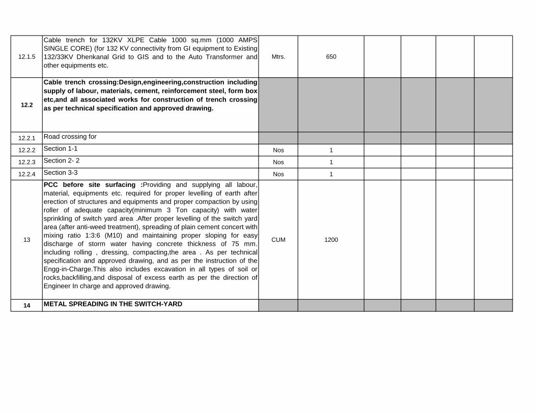
12.1.5
Cable trench for 132KV XLPE Cable 1000 sq.mm (1000 AMPS
SINGLE CORE) (for 132 KV connectivity from GI equipment to Existing
132/33KV Dhenkanal Grid to GIS and to the Auto Transformer and
other equipments etc.
Mtrs. 650
12.2
Cable trench crossing:Design,engineering,construction including
supply of labour, materials, cement, reinforcement steel, form box
etc,and all associated works for construction of trench crossing
as per technical specification and approved drawing.
12.2.1 Road crossing for
12.2.2 Section 1-1 Nos 1
12.2.3 Section 2- 2 Nos 1
12.2.4 Section 3-3 Nos 1
13
PCC before site surfacing :Providing and supplying all labour,
material, equipments etc. required for proper levelling of earth after
erection of structures and equipments and proper compaction by using
roller of adequate capacity(minimum 3 Ton capacity) with water
sprinkling of switch yard area .After proper levelling of the switch yard
area (after anti-weed treatment), spreading of plain cement concert with
mixing ratio 1:3:6 (M10) and maintaining proper sloping for easy
discharge of storm water having concrete thickness of 75 mm.
including rolling , dressing, compacting,the area . As per technical
specification and approved drawing, and as per the instruction of the
Engg-in-Charge.This also includes excavation in all types of soil or
rocks,backfilling,and disposal of excess earth as per the direction of
Engineer In charge and approved drawing.
CUM 1200
14 METAL SPREADING IN THE SWITCH-YARD

14.1
Providing supplying and laying two layers of machine crushed metals
(gravel) fill, the first layer after compaction shall make minimum 50 mm
thickness coarse/ layer of 20 mm nominal size consolidated/
compacted and (by using roller as specified in the specification).A final
layer of 50 mm thickness of machine crushed 20 mm nominal size of
metals(gravel) above the first layer of 50 mm thickness and as per the
technical specification and instruction of Engineer in charge above the
PCC(1:3:6).The total compacted thickness of the metals(20 mm
Nominal) 100mm above the PCC.
CUM 1200
15
Roads: Design, construction of roads and walkways/ shoulders within
sub-station as per specification, layout and approved drawings
complete. This also includes excavation in all types of soil or
rocks,backfilling,and disposal of excess earth as per the direction of
Engineer In charge. Provision of drains on both the side of the roads for
easy discharge of rain water.
15.1
3.75 mtrs Concrete road with shoulder at both the side & shall have
drain on both side of the road as per technical specification indicated in
the civil section( Periphery roads outside switch yard fencing and
colony roads)
MTRS 500
15.2
7 mtrs concrete road with shoulder at both the side as per technical
specification indicated in the civil section(from the switch yard main
gate to all internal roads of the switch yard).Shall have drain on both
side of the road.
MTRS 600
15.3
7 mtrs wide Concrete roads with shoulder as per specification indicated
in the civil section.( for main and approach roads).Shall have drain on
both side of the road.MTRS 100
16
Drainage system:Collection of rainfall data, Design, construction of
storm water drainage scheme, road-culverts, and drains crossing cable
trenches etc. as per specification and approved drawing. This also
includes excavation in all types of soil or rocks,backfilling,and disposal
of excess earth as per the direction of Engineer In charge. All the
switcyard bays , roads water drainage shall be connected to the main
surface drain. As per approved drawing and specification.
16.1 Storm water drain MTRS 1000
16.2 Road-culverts, drain crossings MTRS 100
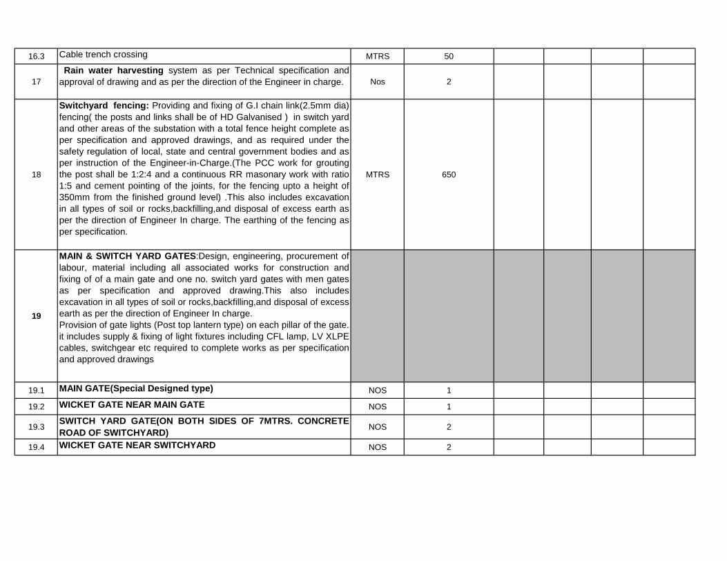
16.3 Cable trench crossing MTRS 50
17
Rain water harvesting system as per Technical specification and
approval of drawing and as per the direction of the Engineer in charge. Nos 2
18
Switchyard fencing: Providing and fixing of G.I chain link(2.5mm dia)
fencing( the posts and links shall be of HD Galvanised ) in switch yard
and other areas of the substation with a total fence height complete as
per specification and approved drawings, and as required under the
safety regulation of local, state and central government bodies and as
per instruction of the Engineer-in-Charge.(The PCC work for grouting
the post shall be 1:2:4 and a continuous RR masonary work with ratio
1:5 and cement pointing of the joints, for the fencing upto a height of
350mm from the finished ground level) .This also includes excavation
in all types of soil or rocks,backfilling,and disposal of excess earth as
per the direction of Engineer In charge. The earthing of the fencing as
per specification.
MTRS 650
19
MAIN & SWITCH YARD GATES:Design, engineering, procurement of
labour, material including all associated works for construction and
fixing of of a main gate and one no. switch yard gates with men gates
as per specification and approved drawing.This also includes
excavation in all types of soil or rocks,backfilling,and disposal of excess
earth as per the direction of Engineer In charge.
Provision of gate lights (Post top lantern type) on each pillar of the gate.
it includes supply & fixing of light fixtures including CFL lamp, LV XLPE
cables, switchgear etc required to complete works as per specification
and approved drawings
19.1 MAIN GATE(Special Designed type) NOS 1
19.2 WICKET GATE NEAR MAIN GATE NOS 1
19.3SWITCH YARD GATE(ON BOTH SIDES OF 7MTRS. CONCRETE
ROAD OF SWITCHYARD)NOS 2
19.4 WICKET GATE NEAR SWITCHYARD NOS 2

20
SECURITY SHED & CUM VISITOR ROOM: Design, engineering,
procurement of labour, material including all associated works for
construction of Security shed near main gate,watch tower shed at the
corners of switch yard as per the approved drawing and instruction of
Engineer in charge.This also includes excavation in all types of soil or
rocks,backfilling,and disposal of excess earth as per the direction of
Engineer In charge. Internal electrification including supply of lighting
fixtures,fan with regulators and provision of incoming AC supply from
the main ACDB/outdoor kiosks installed for street light or colony
quarters. Also includes painting of the building (in side and out side) as
per recommended for colony building in the specification.
20.1
SECURITY SHED:The size of the security shed shall be 3.5
mtrsX5mtrs and height of 3.5mtrs RCC roof,Fly ash Brick masonary
works,plastering and painting and fixing of MS doors and windows.
Internal concealed wiring (including supply of flexible copper FRP 1.1
KV PVC wire,conduits & its accessories,modular type switches & switch
board,Junction boxes with required MCB & Earth leakage detector
switcghear etc),fixing of lighting fixtures with lamps(LED Type) &
switchgear ,ceiling fans of 1400 sweep and regulators( including
supply) and provision of incoming AC supply from the main
ACDB/outdoor kiosks installed for street light or colony quarters. Also
includes painting of the building (in side and out side) as per
recommended for colony building in the specification. (* REMARKS :
FOR SUPPLY OF ALL THE CABLES AS INDICATED ARE COVERED
IN THE supply)}
Nos 1

21
BORE WELL & PUMP HOUSE:Design, engineering, procurement of
labour, material including all associated works for construction of two
nos. borewells for control room building including switch yard and
colony quarters as per specification and approved drawing and
instruction of Engineer in charge.This includes supply and fixing and
commissioning of two nos 5 HP submersible water pump with starter
and other protection. Construction of two nos pump house at ideal
location for fixing of the electrical starter units. The pump house be of
RCC roof and having walls of Brick masonary and plastering and
painting with MS door having locking arrangement. The size of the
room shall be 2.5mtrsX2.5 mtrs having height of 3 mtrs. as per
approved drawing and specification. There shall be approach road to
the pump house. This includes supply of materials,labours and T&P &
excavation of all type of soils including rock and disposal of excess
materials as per instruction of Engineer Incharge.
Supply & laying of LV XLPE 3.5CX.35 sqmm cable from ACDB to pump
house, control gear & earthing of the system etc to complete the
scheme as per approved drawing & instruction of Engineer-in charge.
NOS 2
22
PLATFORM FOR STORING EQUIMENTS:Design, engineering,
procurement of labour, material including all associated works for
construction of a platform for storing of bushings,Instrument
transformers etc, as per specification and approved drawing.This also
includes excavation in all types of soil or rocks,backfilling,and disposal
of excess earth as per the specification,approved drawing and direction
of Engineer In charge. One no platform outside the store shed RR
masonry (compacted) with PCC at the top for storing the transformer
bushings, Instrument transformers, transformer oil drums etc. The
floor size of the platform shall be 15mtrX10 mtr with Galvanised
Corrugated Sheet (Tata Make) top cover and associated MS supporting
structure duly painted.
NOS 1
23
PROVISION OF PLANTATIONS:Provision of plantation of 100 nos fruit
bearing plants and 100 nos decorative plants at different locations, a
garden in front of the control room including preparation of lawn, sypply
of decorative plants like cactus etc.,soil treatment and its plantation
including materials,labour and T&P. As per the instruction of Engineer
in Charge and specification.
LOT 1

24
STONE PITCHING & TOE WALL:Stone pitching including making
of toe walls both at top and bottom, including surface drain both
at top and bottom and partition wall in every 10 mtrs by using
boulders and RR masonry walls respectively. This also includes
excavation in all types of soil or rocks,back filling,and disposal of
excess earth and supply of materials and labour & T&P as per the
direction of Engineer In charge and as per approved drawing and
specification.
24.1 Excavation in Soft & Loose Soil Cum 200
24.2 P.C.C (1:3:6): Lean Concrete Grade M-10 Cum 50
24.3 RR Masonry (1:5) Cum 400
24.4 P.C.C (1:2:4): Lean Concrete Grade M-15 Cum 25
25
STORE SHED:Design, engineering, supply of all labour, T&P, material
including all associated works for construction of store shed as per
specification and approved drawing. This also includes excavation in all
types of soil or rocks,back filling,and disposal of excess earth as per
the specification,approved drawing and direction of Engineer In charge.
One no store shed of floor size 10X10 mtr having Fly ash brick walls
and plastering with RCC roof. The flooring shall be of 75 mm thickness
PCC (mix ratio1:2:4) over RR masonry works (as per standard practice
of flooring). Provision of adequate nos of MS racks (proper paintings
also to be done as per the direction of site in charge) for keeping the
spare materials. The height of the shed shall be 4mtrs above the plinth.
Lot 1

26
CONTROL ROOM BUILDING WITH RAMP: Design,
engineering and construction of switch yard buildings including
the cost of all type of materials, supply of labour, cement,
reinforcement- steel, form work and excavation as per the
approved drawing and technical specification. The column
foundations shall be either shallow/open cast type or pile
type foundation as per the site requirement (The RCC
structure frame should be in the ratio 1:1.5:3).This also includes
excavation in all types of soil or rocks,back filling,and disposal of
excess earth as per the direction of Engineer In charge. As per
approved drawings and specification. This work including anti-
termite treatment, plinth protection, DPC, peripheral drains, water
supply, plumbing, sanitation, fire-fighting, electrification etc
(one Double storied building having the GF: Store room,Bat
room,Maint room, ACDB & DCDB Room, Toilets & stair case &
etc, FF : SAS room, conference room,Office room,Transit rest
room,toilets,pantry etc).
Control Room Building Size: 25 mtrs X 15 Mtrs
The contractor shall finalize the dimensions of the hall & rooms
according to the equipment offered by them providing enough
space & access for erection, operation and maintenance & future
expansion.
26.1
RCC work including MS rods(FE500 and above grade) (including
excavation, PCC, Shuttering, etc. for column ,Beams and roofs
etc) as per technical spec & approved drawings.Lot 1
26.2
Fly ash brick masonry work in cement sand mortar 1: 6 with Fly
ash bricks of class designation 75 as per technical spec &
approved drawings.Lot 1
26.3
Flooring with double charged vitrified tiles with dado in all the
rooms,Bath and toilets shall be provided with anti skid ceramic
tiles(wall of the same also to be provided with ceramic tiles),Acid
proof industrial tiles to be provided on the floor and wall of the
battery room as per technical spec & approved drawings.
Lot 1

26.4
External and internal wall painting with primer coat as per
technical spec mentioned in the civil section. External: One coat
weather coat primer + two coats of weather coat colour paint.
Internal: Two coats wall putty+solvent thinable white primer of
one coat+two coats colour paint.
Lot 1
26.5External and internal wall (External (18mm thk ) and internal (12 mm
thk) wall and ceiling plastering as per technical spec mentioned in the
civil section) and Building internal & external & ceiling paintings as per
Lot
26.6Provision of ceiling in the control room area as per specification
mentioned in the civil section & approved drawings.Lot 1
26.7
Doors and windows shall be of sliding type with locking facility and shall
be of aluminium with glaze of 6mm & windows shall have aluminium
grills. Windows shall be provided with vertical window blinder to protect
from the sun ray. As per technical spec & approved drawing.
Lot 1
26.8
Provision of PHD and other fittings of reputed make for the control
room building (in Toilets,wash room,overhead water tank of adequate
capacity etc) of reputed make,provision of rain water discharge pipes at
different locations and etc as per requirement and approved drawing.
Lot 1
26.9
Internal concealed wiring (including supply of flexible copper FRP 1.1
KV PVC wire,conduits & its accessories,modular type switches & switch
board,Junction boxes with required MCB & Earth leakage detector
switcghear etc),fixing of lighting fixtures & switchgear ,ceiling fans of
1400 sweep and regulators( including supply) ,exhaust fan (including
supply), Erection of all Lighting FIXTURES & LAMPS (LED), D.C
emergency lighting (including supply), as per approved drawing and
direction of Engineer In charge.
Lot 1
26.10Supply, fitting and fixing of stainless steel pf 304 grade in hand railing
using 50mm dia of 2mm thick circular pipe with balustrade of size
32mmx32mmx32mm @0.90mtr C/C and stainless square pipe bracing
Lot 1
26.11Installation of smoke and heat detection system of the building.
Lot 1

27
Construction of township/colony (residential quarters) for staff and
employees of the employer. Layout, design, survey, levelling, site
dressing and clearing of the area, soil investigation, excavation, PCC,
RCC, Fly ash Brick work, plastering ,flooring(flooring shall be with
vitrified tiles of reputed make with a dado of minimum6 inches),fixing of
doors windows and window grills, including all labour, T&P, material
like cement ,sand aggregate, Fly ash Bricks, reinforcements etc with all
bought items required for completion of the quarters as per approved
construction drawings with all facilities for supply of drinking water.
The outer paint shall be applied with weather coat synthetic enamel
paint as per the standard practice of application and the inner paint
shall be applied with distemper of approved quality as per the
instruction and approval of the same by OPTCL. This also includes
excavation in all types of soil or rocks,back filling,and disposal of
excess earth as per the direction of Engineer In charge. Internal
electrical wiring with fixing of light fixtures and fans with electronic
regulators and exhaust fans as per technical specification and
approved drawing. Construction of over head RCC tank(1000 ltrs
capacity one for each quarters), sewerage disposal and connection
with main sewerage/ septic tank and soak pit, storm water and surface
drainage, culverts, roads, with suitable radius on the curves and its
connection with main road the substation, street lighting, internal
lighting, internal plumbing and sanitation including internal/external
finishing of quarters etc. required for completion of the town ship.
(RCC column structure frame and the Fly ash Bricks to be used shall
be fly ash Fly ash Brick, all the door and window frame & panels shall
be aluminium with adequate size as indicated in the TS and also as per
the National Building Code adopted.
27.1 "D" type Quarter As per technical specification: 1 no quarter on
ground floor & the size of quarter plinth area shall be 120 Sq
Mtrs(appox)SQ.MTRS 120
27.2
"E" type Quarter As per technical specification (one no. two
storied flat. Each flat shall be with 2 nos quarters on
ground floor & 2 Nos quarters on 1st floor).(There shall be 4
Nos quarters to be accommodated in one flat as E1,E2,E3 &
E4)
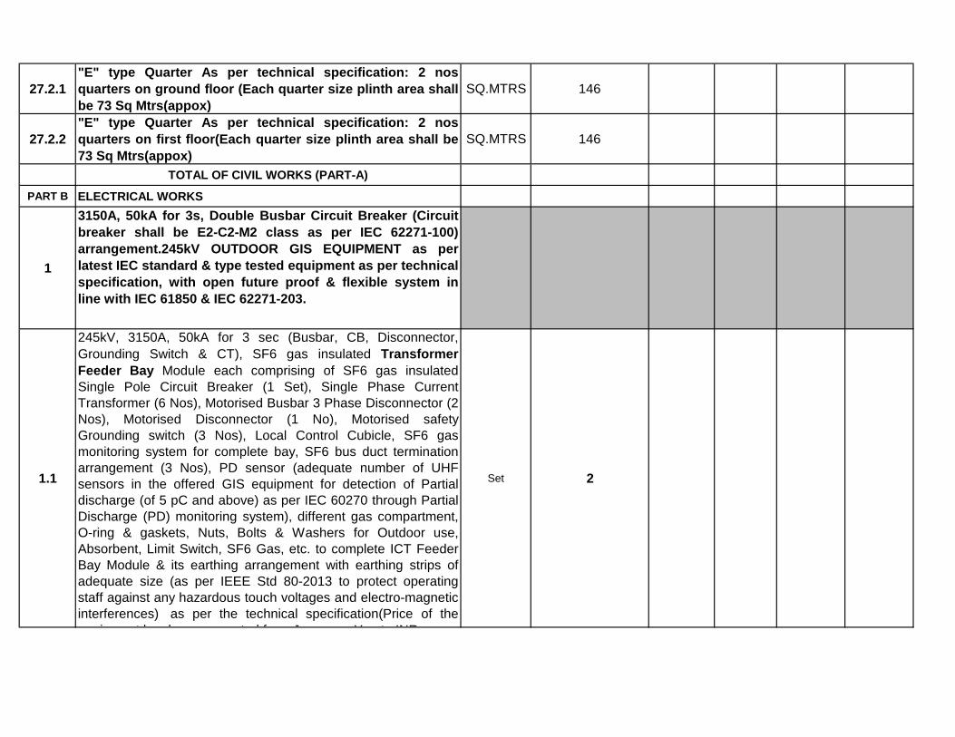
27.2.1
"E" type Quarter As per technical specification: 2 nos
quarters on ground floor (Each quarter size plinth area shall
be 73 Sq Mtrs(appox)
SQ.MTRS 146
27.2.2
"E" type Quarter As per technical specification: 2 nos
quarters on first floor(Each quarter size plinth area shall be
73 Sq Mtrs(appox)
SQ.MTRS 146
TOTAL OF CIVIL WORKS (PART-A)
PART B ELECTRICAL WORKS
1
3150A, 50kA for 3s, Double Busbar Circuit Breaker (Circuit
breaker shall be E2-C2-M2 class as per IEC 62271-100)
arrangement.245kV OUTDOOR GIS EQUIPMENT as per
latest IEC standard & type tested equipment as per technical
specification, with open future proof & flexible system in
line with IEC 61850 & IEC 62271-203.
1.1
245kV, 3150A, 50kA for 3 sec (Busbar, CB, Disconnector,
Grounding Switch & CT), SF6 gas insulated Transformer
Feeder Bay Module each comprising of SF6 gas insulated
Single Pole Circuit Breaker (1 Set), Single Phase Current
Transformer (6 Nos), Motorised Busbar 3 Phase Disconnector (2
Nos), Motorised Disconnector (1 No), Motorised safety
Grounding switch (3 Nos), Local Control Cubicle, SF6 gas
monitoring system for complete bay, SF6 bus duct termination
arrangement (3 Nos), PD sensor (adequate number of UHF
sensors in the offered GIS equipment for detection of Partial
discharge (of 5 pC and above) as per IEC 60270 through Partial
Discharge (PD) monitoring system), different gas compartment,
O-ring & gaskets, Nuts, Bolts & Washers for Outdoor use,
Absorbent, Limit Switch, SF6 Gas, etc. to complete ICT Feeder
Bay Module & its earthing arrangement with earthing strips of
adequate size (as per IEEE Std 80-2013 to protect operating
staff against any hazardous touch voltages and electro-magnetic
interferences) as per the technical specification(Price of the
equipment has been converted from Japanese Yen to INR as
Set 2

1.2
245kV, 3150A, 50kA for 3 sec (Busbar, CB, Disconnector,
Grounding switch, CT & PT), SF6 gas insulated Line Feeder
Bay Module each comprising of SF6 gas insulated Single Pole
Circuit Breaker (1 Set), Single Phase Current Transformer (6
Nos), Single phase Line Potential Transformer (4 winding) (3
Nos), Motorised 3 Phase Busbar Disconnector (2 Nos),
Motorised safety Grounding switch (2 Nos), Motorised 3 Phase
Disconnector with high speed fault making Motorised Grounding
switch (1 No), Local Control Cubicle, SF6 gas monitoring system
for complete bay, SF6 bus duct termination arrangement (3
Nos), PD sensor (adequate number of UHF sensors in the
offered GIS equipment for detection of Partial discharge (of 5 pC
and above) as per IEC 60270 through Partial Discharge (PD)
monitoring system), different gas compartment, O-ring &
gaskets, Nuts, Bolts & Washers for Outdoor use, Absorbent,
Limit Switch, SF6 Gas, etc. to complete Line Feeder Bay Module
& its earthing arrangement with earthing strips of adequate size
(as per IEEE Std 80-2013 to protect operating staff against any
hazardous touch voltages and electro-magnetic interferences) as
Set 4
1.3
245kV, 3150A, 50kA for 3 sec (Busbars, Disconnector,
Grounding switch & bus PT), 1 Phase Isolated Bus-PT Bay
Module comprisig of SF6 gas insulated metal enclosed busbars
each enclosed in bus enclosures running along the length of the
switchgear to interconnect each of circuit breaker bay module.
Each busbar set shall be complete with Single phase bus
Potential Transformer (4 winding) (3 Nos), Motorised 3 Phase
Disconnector (1 No) , Motorised Busbar safety Grounding switch
(1 No), Local Control Cubicle, SF6 gas monitoring system PD
sensor (adequate number of UHF sensors in the offered GIS
equipment for detection of Partial discharge (of 5 pC and above)
as per IEC 60270 through Partial Discharge (PD) monitoring
system), different gas compartment, O-ring & gaskets, Nuts,
Bolts & Washers for Outdoor use, Absorbent, Limit Switch, SF6
Gas, etc. to complete the bus & its earthing arrangement with
earthing strips of adequate size (as per IEEE Std 80-2013 to
protect operating staff against any hazardous touch voltages and
electro-magnetic interferences) as per the technical
Set 1

1.4
245kV, 3150A, 50kA for 3 sec (CB, Disconnector, Grounding
switch & CT), SF6 gas insulated Bus Coupler Bay Module
comprising of SF6 gas insulated Single Pole Circuit Breaker (1
Set), Single Phase Current Transformer (6 Nos), Motorised 3
Phase Disconnector (2 Nos), Motorised safety Grounding switch
(2 Nos), Local Control Cubicle, SF6 gas monitoring system, PD
sensor (adequate number of UHF sensors in the offered GIS
equipment for detection of Partial discharge (of 5 pC and above)
as per IEC 60270 through Partial Discharge (PD) monitoring
system), different gas compartment, O-ring & gaskets, Nuts,
Bolts & Washers for Outdoor use, Absorbent, Limit Switch, SF6
Gas, etc. to complete Bus Coupler Bay Module & its earthing
arrangement with earthing strips of adequate size (as per IEEE
Std 80-2013 to protect operating staff against any hazardous
touch voltages and electro-magnetic interferences) as per the
technical specification.
Set 1
1.5
245kV, 3150A, 50 kA, 3 sec, single phase, SF6 gas Insulated
Bus Duct outside GIS Bay along with associated Support
structure arrangement bends, joints,accessories, & its earthing
arrangement with earthing strips of adequate size (as per IEEE
Std 80-2013 to protect operating staff against any hazardous
touch voltages and electro-magnetic interferences) as per the
technical specification.
RM 700
1.6
245kV, 3150A, 50kA SF6/Air BUSHING (Bushing shall be of
Polymer / composite insulator type and shall be seamless sheath
of a silicone rubber compound. The hollow silicone composite
insulators shall comply as per IEC 61462 and IEC 62217. The
design of the composite insulators shall be tested and verified
according to IEC 61462) FOR CONNECTING GIS TO AIS along
with support structure.
No. 18

1.7
Portable Partial Discharge Monitoring System (PDM):
245kV system shall have Portable Partial Discharge Monitoring
System (PDM) & shall be capable for measuring PD in charged
GIS environment, bandwidth in order of 100MHz–2GHz &
provision to select a wide range of intermediate bandwidths and
the principle of operation shall be based on UHF principle of
detection. The Detection and measurement of PD and bouncing
particles having in built large coloured LCD for displaying and
storing facility in the instrument for further analysis to locate
actual source of PD such as free conducting particles, floating
components, voids in spacers, particle on spacer surfaces etc.
Set 1
2
2000A, 40kA for 3s, Double Busbar Circuit Breaker (Circuit
breaker shall be E2-C2-M2 class as per IEC 62271-100)
arrangement.
145kV OUTDOOR GIS EQUIPMENT as per latest IEC
standard & type tested equipment as per technical
specification, with open future proof & flexible system in
line with IEC 61850 & IEC 62271-203.
2.1
145kV, 2000A, 40kA for 3 sec (Busbar, CB, Disconnector,
Grounding Switch & CT), SF6 gas insulated Transformer Feeder
Bay Module each comprising of SF6 gas insulated Single Pole
Circuit Breaker (1 Set), Single Phase Current Transformer (6
Nos), Motorised Busbar 3 Phase Disconnector (2 Nos),
Motorised Disconnector (1 No), Motorised safety Grounding
switch (3 Nos), Local Control Cubicle, SF6 gas monitoring
system for complete bay, SF6 bus duct termination arrangement
(3 Nos), PD sensor (adequate number of UHF sensors in the
offered GIS equipment for detection of Partial discharge (of 5 pC
and above) as per IEC 60270 through Partial Discharge (PD)
monitoring system), different gas compartment, O-ring &
gaskets, Nuts, Bolts & Washers for Outdoor use, Absorbent,
Limit Switch, SF6 Gas, etc. to complete ICT Feeder Bay Module
& its earthing arrangement with earthing strips of adequate size
(as per IEEE Std 80-2013 to protect operating staff against any
hazardous touch voltages and electro-magnetic interferences)
Set 2

2.2
145kV, 2000A, 40kA for 3 sec (Busbar, CB, Disconnector,
Grounding switch, CT & PT), SF6 gas insulated Line Feeder Bay
Module each comprising of SF6 gas insulated Single Pole Circuit
Breaker (1 Set), Single Phase Current Transformer (6 Nos),
Single phase Line Potential Transformer (4 winding) (3 Nos),
Motorised 3 Phase Busbar Disconnector (2 Nos), Motorised
safety Grounding switch (2 Nos), Motorised 3 Phase
Disconnector with high speed fault making Motorised Grounding
switch (1 No), Local Control Cubicle, SF6 gas monitoring system
for complete bay, SF6 bus duct termination arrangement (3
Nos), PD sensor (adequate number of UHF sensors in the
offered GIS equipment for detection of Partial discharge (of 5 pC
and above) as per IEC 60270 through Partial Discharge (PD)
monitoring system), different gas compartment, O-ring &
gaskets, Nuts, Bolts & Washers for Outdoor use, Absorbent,
Limit Switch, SF6 Gas, etc. to complete Line Feeder Bay Module
& its earthing arrangement with earthing strips of adequate size
(as per IEEE Std 80-2013 to protect operating staff against any
hazardous touch voltages and electro-magnetic interferences) as
Set 2
2.3
145kV, 2000A, 40kA for 3 sec (Busbars, Disconnector,
Grounding switch & bus PT), 1 Phase Isolated Bus-PT Bay
Module comprisig of SF6 gas insulated metal enclosed busbars
each enclosed in bus enclosures running along the length of the
switchgear to interconnect each of circuit breaker bay module.
Each busbar set shall be complete with Single phase bus
Potential Transformer (4 winding) (3 Nos), Motorised 3 Phase
Disconnector (1 No) , Motorised Busbar safety Grounding switch
(1 No), Local Control Cubicle, SF6 gas monitoring system PD
sensor (adequate number of UHF sensors in the offered GIS
equipment for detection of Partial discharge (of 5 pC and above)
as per IEC 60270 through Partial Discharge (PD) monitoring
system), different gas compartment, O-ring & gaskets, Nuts,
Bolts & Washers for Outdoor use, Absorbent, Limit Switch, SF6
Gas, etc. to complete the bus & its earthing arrangement with
earthing strips of adequate size (as per IEEE Std 80-2013 to
protect operating staff against any hazardous touch voltages and
electro-magnetic interferences) as per the technical
Set 1

2.4
145kV, 2000A, 40kA for 3 sec (CB, Disconnector, Grounding
switch & CT), SF6 gas insulated Bus Coupler Bay Module
comprising of SF6 gas insulated Single Pole Circuit Breaker (1
Set), Single Phase Current Transformer (6 Nos), Motorised 3
Phase Disconnector (2 Nos), Motorised safety Grounding switch
(2 Nos), Local Control Cubicle, SF6 gas monitoring system, PD
sensor (adequate number of UHF sensors in the offered GIS
equipment for detection of Partial discharge (of 5 pC and above)
as per IEC 60270 through Partial Discharge (PD) monitoring
system), different gas compartment, O-ring & gaskets, Nuts,
Bolts & Washers for Outdoor use, Absorbent, Limit Switch, SF6
Gas, etc. to complete Bus Coupler Bay Module & its earthing
arrangement with earthing strips of adequate size (as per IEEE
Std 80-2013 to protect operating staff against any hazardous
touch voltages and electro-magnetic interferences) as per the
technical specification.
Set 1
2.5
Portable Partial Discharge Monitoring System (PDM):
145kV system shall have Portable Partial Discharge Monitoring
System (PDM) & shall be capable for measuring PD in charged
GIS environment, bandwidth in order of 100MHz–2GHz &
provision to select a wide range of intermediate bandwidths and
the principle of operation shall be based on UHF principle of
detection. The Detection and measurement of PD and bouncing
particles having in built large coloured LCD for displaying and
storing facility in the instrument for further analysis to locate
actual source of PD such as free conducting particles, floating
components, voids in spacers, particle on spacer surfaces etc.
Set 1
3 245 KV,2000A,40KA,ISOLATORS
3.1 245 KV, 2000A, 40KA, Center break ISOLATORS WITH EARTH SWITCH NOS 4
4 216 KV, METAL OXIDE SURGE ARRESTOR,10 KA, class III NOS 18
5 220 KV Bus Post Insulators NOS 6
6 145 KV,1250A,31.5KA,ISOLATORS
6.1 145 KV, 2000A, 40KA, Center break ISOLATORS WITH EARTH SWITCH NOS 2
7 120 KV METAL OXIDE SURGE ARRESTOR, 10 KA, Class III NOS 12

8
30 KV, METAL OXIDE SURGE ARRESTOR, 10kA, Class II (AIS) as per technical
specification. NOS 9
9 BUS-BAR STRINGING
9.1 Supply of labour,T&P and other necessary arrangements for
stringing of bus bar conductors,hoisting of single or double
insulator strings,Single or Double Hard-wares Fittings, Clamp &
connectors, as per requirements,
Jumpers,connectionsEquipments,testing,commissioning etc. as
per the instruction of Engineer-in charge.
9.1.1 ACSR Moose(Single) Per Mtr. 900
9.1.2 Twin Conductor /Phase/Mtr. Per Mtr. 1000
12
Laying and termination of EHV/HV XLPE Power copper conductor
cable for the GIS system as per IS7098 & IEC60840 including
installation of indoor & outdoor cable termination kit and associated
cable accessories & clamps as per technical specification and direction
of Engineer-in -charge.
12.1
132KV XLPE Copper Cable 1000 sq. mm Single Core (from 132 KV
GIS to 132KV Gantry) including installation of indoor & outdoor cable
termination kit
Mtrs 3000
12.2
33KV XLPE Copper Cable 300 sq. mm Single Core (For connectivity to
Station Transformer) including installation of indoor & outdoor cable
termination kit
Mtrs 1000
13 EARTH WIRES & IT'S HARDWARES & FITTING
13.1Earthing Spikes of 9 mtr long each and Its Fittings in all respect. (220
kv side)NOS 5
13.2Earthing Spikes of 7 mtr long each and Its Fittings in all respect. (132
kv side)NOS 3

14
SUB-STATION EARTH-MAT
Substation earth-mat Design, engineering, supply inclusive of corrosion
protection measures if any,laying of earth-mat conductors of Hot dip
galvanized flats of size 75X10mm to the approval of Project Manager,
excavation, welding/jointing ,application of two coats of bituminous
Paint,wrapping of HT Tape etc of ground conductors along with risers
(of size 50X6 mm GI flats) etc back filling and good
compaction,grounding driven rods(40 mm MS solid rod),perforated GI
pipes for treated earth pits(with details of treatment as per IS). The
spacing between the earth conductor not more than 5 mtrs(both way)
and to be buried at depth of 700mm from the finished ground level. For
provision of treated earth-pit and untreated earth pit, refer the
specification for designing. Provision of water taps inside the switch
yard areas and peripheral treated and un-treated earth pit are required
to be provided for watering the treated earth pits. The no. of treated and
un treated earth pits are to be done as per the practice and as indicated
in the drawing for different equipments. This is as per approved
drawing and specification.
14.1 75X10 mm GI Flat Mtr. 8000.000
14.2 Connection of Earthing Riser of size 50X6 mm GI Flat Mtr. 1634.000
14.350MM GI PIPE FOR TREATED EARTH PIT ELECTRORDE WITH
CHAMBER AND COVERNos. 50
14.4 40 MM MS ROD FOR NON-TREATED EARTH PIT ELECTORDE Nos. 120
15
G.I Cable Trays including support GI angle suitable for different
sections i.e. Section:1-1,2-2,3-3 & 4-4 along with its accessories as per
TS.
15.1 G.I Cable Trays(size: 450x75x2500mm) MTRS 2000
15.2 G.I Cable Trays(size: 300x75x2500mm) MTRS 2500
15.3 G.I Cable Trays(size: 150x75x2500mm) MTRS 2000
15.4 Support G. I angle 50x50x6 mm for cable tray MT 4
16SUB STATION SWITCYARD BMK,AC CONSOLE & OTHER
MARSHALLING BOXES
16.1BAY MARSHALLING KIOSK (02 Nos. in 220 KV Bay,01 Nos. in 132
KV Bay BAY )NOS 3

16.2SWITCH YARD AC CONSOLE FOR LIGHTING (01 Nos. in 220 KV
bay, 01 No. in 132 kv Bay )NOS 2
16.3SWITCH YARD RECEPTACLE BOARD FOR TFR OIL FILTERATION
(01 No. near each 220/132 Auto Transformers)NOS 2
16.4SWITCH YARD RECEPTACLE BOARD FOR WELDING & OTHER
EMERGENCY (01 No.)NOS 1
16.5 CVT Out door console boxes (CVT = 220KV - 4nos., 132KV-2) NOS 6
16.6 Apex meter panel NOS 1
16.7 0.2 Class ABT Compliant Apex energy Meter. NOS 4
17
ERECTION OF SWITCH YARD STRUCTURES (LATTICE TYPE FOR
COLUMN & BEAMS AND PIPE TYPE FOR ALL EQUIPMENT) FOR
220KV & 132KV CLASS INCLUDING FOUNDATION BOLTS &
NUTS.
17.1 DIFFERENT TYPES OF COLUMNS WITH DETAILS
17.1.1 P1S-220 KV (NOMINAL UNIT WT- 4.5 MT)- 5 NOS) MT 22.500
17.1.2 T1S 132KV (NOMINAL UNIT WT-1.2MT (3 NOS.) MT 3.600
17.2 DIFFERENT TYPE OF BEAMS WITH DETAILS
17.2.1 Q1-220KV (NOMINAL UNIT WT- 1.5 MT) (4 NOS.) MT 6.000
17.2.2 G1 - 132KV (NOMINAL UNIT WT-0.62MT) ( NOS) MT 1.240
17.3 TOTAL WEIGHT OF COLUMN & BEAMS MT 33.340
17.4
ERECTION OFEQUIPMENT SUPPORT STRUCTURES (LATTICE
TYPE) FOR ALL 220KV & 132 KV EQUIPMENTS INCLUDING
FOUNDATION BOLTS & NUTS
17.4.1 ISOLATORS-220KV ( SI with E/S 4 Nos.) MT 5.084
17.4.2 ISOLATORS-132KV ( SI with E/S-2 Nos.) MT 1.318
17.4.3 CVTS-220 KV (12 Nos.) MT 2.652
17.4.4 CVTS-132 KV (6 Nos ) MT 1.344
17.4.5 Surge Arrester-220 KV( 18 Nos.) MT 5.258
17.4.6 Surge Arrester-132 KV( 12 Nos.) MT 3.288
17.4.7 BPI-220 KV (6Nos.) MT 13.469
17.4.8 Cable Termination Port -132 KV (12Nos) MT 4.200

17.5 TOTAL WEIGHT OF EQUIPMENT STRUCTURES MT 36.612
17.6Total weight of GI Nuts and Bolts for Columns, Beams &
Equipment StructuresMT 1.831
18 GENERAL EQUIPMENT & SUBSTATION ACCESSORIES
18.1POWER CABLES,1.1KV,XLPE & PVC ARMOURED, ALUMINIUM
CONDUCTOR (As per Specification)
18.1.1 XLPE 3.5 CX185 mm2
MTR 500
18.1.2 XLPE 3.5 CX120 mm2
MTR 500
18.1.3 PVC 3.5 CX70 mm2
MTR 300
18.1.4 PVC 3.5 CX35 mm2
MTR 500
18.1.5 PVC 4 CX 16 mm2
MTR 1000
18.1.6 PVC 4CX 6 mm2
MTR 1000
18.1.7 PVC 2CX 6 mm2
MTR 2000
18.2CONTROL CABLES,1.1 KV, PVC,STRANDED COPPER(As per
specification)
18.2.1 4 CX 2.5 mm2
MTR 6000
18.2.2 5 CX 2.5 mm2
MTR 4000
18.2.3 7CX 2.5 mm2
MTR 5000
18.2.4 10 CX 2.5 mm2
MTR 10000
18.2.5 12 CX 2.5 mm2
MTR 5000
18.2.6 16 CX 2.5 mm2
MTR 2000
18.2.7 19 CX 2.5 mm2
MTR 2000
18.2.8 1CX 120 mm2 BAT TO BAT CHARGER & CHARGER TO DCDB MTR 300
19 ACCESSORIES FOR PLCC SYSTEM With OPGW cable
19.1 48 Fibre Optic Approach cable along with HDPE Pipes KM 0.50
19.2 Optical line Terminal Equipment(OLTE) -STM4 type SDH equipment with
integrated MUX & tributary cards for speech & data ports for interfacing of
Speech & data which should be compatible with existing OPTCL system
No
1
19.3 Digital Teleprotection Equipment and accessories to be suitable for
interfacing with SDHMUX
No1

19.4 Supply of FODP(Fibre Optic Distribution Panel)48 F: Indoor type,rack
mounted with FCPC coupling and pig tails(DWSm Fibre)
No
1
19.5 48 V, 300 AH, maintenance free VRLA Battery set. Set 1
19.6 SMPS based Battery Charger of 75A suitable for 48V VRLA Battery set No 1
19.7 2.5 sq. mm muti strand 2 core control cable(power
supply,Transducer/MFT PT supply)Metre 300
19.8 2.5 sq. mm multi strand 4 core control cable(Transducer/MFT CT
supply)Metre 300
19.9 1.5 sq. mm multi strand 10 core control cable(Digital Input) Metre 200
19.10 10 sq. mm 2 core multi strand control cable(Battery) Metre 100
19.11 48V DCDB Set 1
19.12 Earth Flat, Cable Tray, Telephone cable, Foundation rail, Junction Box,.Lot 1
20
ERECTION,FILTERATION,TESTING & COMMISSIONING OF
POWER TRANSFORMER & ITS OTHER RELATED ACCESSORIES

20.1
ERECTION OF THE TRANSFORMERS AND ITS
ACCESSORIES ON THE PLINTH AND PLACING IN POSITION,
ERECTION OF ACCESSORIES OF THE TRANSFORMERS,
EART-HING AS PER STANDARD(INCLUDING SUPPLY OF
MATERIALS),VACUUM TREATMENT OF THE TANK AND
WINDING,OIL FILTRATION(INCLUDING SUPPLY OF
VACUUM CUM OIL FILTER MACHINE),SUPPLY & LAYING OF
ALL TYPES OF CONTROL & POWER CABLES PERTAINING
TO TRANSFORMERS ,TESTING AND COMMISSIONING
INCLUDING ALL TESTS OF THE OILS AS PER STIPULATION
IN THE STANDARD APPROVED TESTING LABORATORY
AND AS PER THE INSTRUCTION OF THE ENGINEER IN
CHARGE.THIS INCLUDE ALL RELATED WORKS FOR
ERECTION,TESTING AND COMMISSIONING OF THE
POWER TRANSFORMERS.(CONTRACTOR TO ARRANGE
POWER SUPPLY FOR FILTRATION AND VACUUM
TREATMENT WORKS).IT ALSO INCLUDES SUPPLY OF ALL
MATERIALS FOR ERECTION INCLUDING T&P's.
160MVA, 220/132/33KV Auto Transformer-
NOS 2
20.2STATION TRANSFORMER 33KV/0.43 V,500 KVA (Confirming to
Energy Efficiency Level 2 -AS PER SPECIFICATION & relevant IS)NOS 2

20.3
One no. 4 pole structure (HDG Type) alongwith other equipment &
materials for two nos station transformers:
1.4 Pole structure (using 200X100 mm RS Joist)
2. Channel & Angle FOR BRACING OF, CHANNEL for the SA &
Isolator & HG fuse etc.
3. 90 KN Disc/composite long rod Insulators for 33 KV (48 nos./12
sets) for bus, Bus stringing using ACSR moose conductor & tension
hardwares,other clamps & connectors etc as per requirement.
4. 2sets of 33 KV Isolator (800 AMP) for 33 KV side of station trafo.
5. 2sets of 33 KV HG FUSE.
6. 100 Sq mm AAAC conductor suitable for connection between HG
fuse & station transformer bushing.
7. 2 sets of LT OUT DOOR KIOSK MADE OUT OF 3mm CRCA sheet
Gl MARSHALLING BOX suitable for outdoor mounting. The bus bar
suitable for 1000 AMP shall be arranged in the out door kiosk and other
Facility like two sets of 400 Amps MCCB for incoming & outgoing with
required sizes of terminal studs for power cable termination & any
other accessories required.
AII materials shall be As per relevant latest IS & as per the direction of
Engg. in charge
SETS 2
21
Switch yard lighting: Design, engineering, procurement of labour,
material including all associated works for construction of switch yard
lightings as per technical specification and approved drawings. The
fixture shall be of reputed make (Philips/CGL/Bajaj/ other approved
make of OPTCL) and fixtures shall be metalhalide lamps and proper
cabling from the lighting outdoor distribution boards to the junction
boxes and from junction boxes to the fixtures. The lighting fixtures are
to be installed on the switch yard structures. The quantity of such
fixtures are to be designed and to be ascertained.
21.1SUB-STATION SWITCH YARD LIGHTING : IT INCLUDES SUPPLY
OF FIXTURES & LAMPS (LED) of reputed make
(Philips/CGL/Bajaj/other approved make of OPTCL) with switch gear,GI
SET 60

21.2
STREET LIGHTING: GI Tubular Pole: (410-SP-24: IS 2713-Part-II-
1980 or latest) Length of pole 8.5 mtrs(minimum weight 158 Kgs). &
LED light fittings etc.
(ALL THE STREET LIGHT POLE SHALL BE OF GI TUBULAR POLE
AND PROVISION OF A GI JUNCTION BOX WITH SUITABLE
COVERS AT A HEIGHT OF 1 METRE FROM THE GROUND. THE
JUNCTION BOX SHALL HAVE PROVISION OF FUSES, BUSES,
CONNECTORS FOR CABLE IN AND OUT. ( IT INCLUDES SUPPLY
OF LED LIGHTING FIXTURES WITH LAMPS of 100 Watts of
reputed make (Philips/CGL/Bajaj/other approved make of OPTCL) & as
per technical specification. (* REMARKS : FOR SUPPLY OF ALL THE
CABLES AS INDICATED ARE COVERED IN THE CABLE ITEMS AS
INDICATED ABOVE )
SET 25
21.3
OUTDOOR KIOSK (HDG type) FOR STREET LIGHTING PURPOSE
HAVING 2 NOS 200 AMP SWITCH FUSE UNITS AND , 6 NOS.OUT
LETS OF 32 AMP MCB FOR STREET LIGHTING. (SUITABLE FOR
XLPE CABLES(3.5 CORE 120 SQMM) FROM MAIN ACDB FROM
CONTROL ROOM TO THE OUT DOOR KIOSK. XLPE CABLE OF 4C
X 16 SQMM FROM OUTDOOR KIOSK TO THE STREET LIGHT
POLES AND 4CX6 SQMM FROM POLE TO POLE AND 2CX6 SQMM
FROM POLE TO LIGHTING FIXTURES. > 1 NO. OUTDOOR KIOSK
FOR COLONY SUPPLY PURPOSE HAVING (* REMARKS : FOR
SUPPLY OF ALL THE CABLES AS INDICATED ARE COVERED IN
THE CABLE ITEMS AS INDICATED ABOVE )
SET 2
21.4
40 Mtrs heigh Monopole (HDG) Lighting cum Lightning Mast including
LED lighting fixtures (240 watts each minimum 8 Nos.) with control
gear panel etc suitable for wind zone-V , with all other accessories like
motor for hoisting/lowering the lighting platform & other switchgear and
lighting control panel including required cable(copper) & other
accessories etc.
SET 2
22
2 TR CAPACITY SPLIT AIR CONDITIONING UNITS WITH REMOTE
CONTROL FACILITY: INCLUDING SUPPLY OF 5 star rated AIR
CONDITIONERS, Automatic Voltage Stabiliser,CONTROL BOXES ETC FOR
COMPLETING THE A.C SCHEME.(AS PER SPECIFICATION ) FOR
CONTROL ROOM, CARRIER ROOM & CONFERENCE ROOM.,OFFICE
ROOM etc which includes all type of cables & wires and a main control switch
gear kiosk having sufficient outlet for each air conditioner unit.
SET 20

23
FIRE FIGHTING SYSTEM(PORTABLE AND WHEEL MOUNTED
SETS FOR CONTROL ROOM,EQUIPMENT LIKE TRANSFORMER
AND OTHER AREAS AS PER TECH SPEC(REFER TS-INST TO
BIDDER BEFORE DESIGN-SL NO 16-ANNEXURE - I)
23.1 FOAM TYPE-9 LTRS NOS 5
23.2 DRY CHEMICAL POWDER(TROLLEY MOUNTED)- 22.5 KGS NOS 6
23.3 DRY POWDER TYPE - 5 KGS NOS 6
23.4 CO2 - 4.5 KGS NOS 6
23.5 CO2 - 9 KGS NOS 6
23.6 CO2 (TROLLY MOUNTED)- 22.5 KGS NOS 4
23.7 9 litre Water type Nos. 4
23.8 50 Litres Mechanical Foam type Nos. 2
23.9 FIRE BUCKET (6 NOS IN EACH STAND) WITH STAND SET 5
24
SUBSTATION AUTOMATION SYSTEM FOR 220/132 KV
SUBSTATION ON PRP MODE: Design , engineering , drawing,
supervision, installation , testing & commissioning of Substation
Automation system alongwith Supply of the following 220 and 132 kV
level of protection panels consisting of Bay control Units & numerical
protection relays and other auxiliary relays suitable for SAS as per
technical specification.
(220KV side: COMPRISING OF 04 Nos. FEEDER BAYS + 02
TRANSFORMER BAYS + 01 Nos BUS COUPLER BAY & 132 KV
side: COMPRISING OF 02 Nos. FEEDER SAYS + 02 Nos
TRANSFORMER BAYS + 01 No. BUS COUPLER BAY)
NOTE: All protective relays & BCU shall be numerical type.
24.1Yard AC Kiosk :5000 mm (L)x4000mm (W)x 3300mm (H) with AC, as per the
Specification;Nos. 3

24.2
Gate way panel for Sub-Station Automation (in PRP as per the
specification & indicative drg ) system (for All 220 & 132 KV side bays
including the future bays),other accessories (comprising servers, engg.
Station, works station (Main & standby), Remote station control, Colour
Laser jet Printers & dot matrix printer for local station as per
requirement and also for remote station, Ethernet Switches , LIU, Red
Box, Multimode glass fibre Doublle jacket armoured optical cables,
special cables like F.O patch cord & armoured FO cables of adequate
length etc required for the system in all respect as per latest IEC 61850
standard, Inverters of required capacity & rating (3KVA-Input shall be
both A.C & D.C and output shall be A.C) etc as per TS. A Full HD LED
screen of 70 inches for display,SAS furnitures of Godrej make &
including all type of accessories & as per technical specification.
SET 1
24.3
BCU for Substation Auxilliary System (Datas for monitoring of
Station AC, Station DC, Lighting, Fire fighting, Air conditioning, Diesel
generator etc. as per the site requirement)
SET 1
24.5 GPS System with PTP, IRIG-B, SNTP SET 1
24.6 220 KV SIDE PROTECTION & OTHER PANELS
24.6.1 FEEDER PROTECTION PANEL (MAIN-I , MAIN-II & BACK-UP
PROTECTION WITH AUTO RECLOSURE DISTANCE PROTECTION NOS 2
24.6.2
TRANSFORMER PROTECTION PANEL (DIFFERENTIAL I , REF I &
BACK-UP PROTECTION & BCU for 220 KV side) & (Bay control unit-
BCU for 132 KV side) CONSIDERING HV & LV side of 220/132 KV,
160 MVA Auto transformer with all other relays & component required
for complete prtection,control etc as per TS and also suitable for
substation automation system.
NOS 2
24.6.3
BUS COUPLER PROTECTION PANEL with Bay control unit (BCU) &
Back-up protection relay with with all other relays & component
required for complete prtection,control etc as per TS and also suitable
for substation automation system.
NOS 1
24.6.4
BUS-BAR PROTECTION PANEL ( Provision of bus bar modules for
the future bays(two nos) and with with all other relays & component
required for complete prtection etc as per TS and also suitable for
substation automation system.
SET 1
24.7 132 KV SIDE PROTECTION PANELS

24.7.1
132KV FEEDER PROTECTION PANEL (MAIN-I & BACK-UP
PROTECTION DISTANCE PROTECTION with Bay control unit
(BCU) for substation automation system.
(b) Supply of Main-I Line differential Protection only along with all
other accessories required for succesful operation between Dhenkanal-
A & Dhenkanal-B .
NOS 6
24.7.2
132 KV BUS COUPLER PROTECTION Panel with Bay control unit
(BCU) with with all other relays & component required for complete
prtection,control etc as per TS and also suitable for substation
automation system.
NOS 1
25 AC & DC SYSTEM
25.1 AC SYSTEM
25.1.1
MAIN ACDB,(HAVING 800A, 50KA, DRAWOUT TYPE ACB WITH 3
O/C,E/F,U/V RELAYING FACILITY INDOOR TYPE AS PER
SPECIFICATION.(MAIN DB-1,MAIN DB-2 WITH B/C)
SET 1
25.1.2ACDB (HAVING 400A MCCB) AS PER SPECIFICATION (ACDB-1,
ACDB-2 WITH B/C)SET 1
25.1.3
MAIN LIGHTING DISTRIBUTION BOARD (HAVING 250A MCCB AS
INCOMER)AS PER SPECIFICATION (WITH DB-1,DB-2 & B/C) SET 1
25.1.4INDOOR LIGHTING DISTRIBUTION BOARD AS PER
SPECIFICATION. (WITH DB-1,DB-2 & B/C)SET 1
25.1.5 EMERGENCY LIGHTING DISTRIBUTION BOARD SET 1
25.1.6 INDOOR RECEPTACLE BOARD SET 1
25.2 DC SYSTEM
25.2.1
220 V DCDB (HAVING 100A DC MCCB AS INCOMER, E/F (EARTH
LEAKAGE), UNDER & OVER VOLTAGE AS PER SPECIFICATION
(DC DB-1,DC DB-2 & B/C)
SET 1
25.2.2 220 V DC EMERGENCY DISTRIBUTION BOARD SET 1
26 BATTERY (350 AH PLANTE TYPE) FOR 220 V DC SET 2
27BATTERY CHARGER FOR 220 V, 350 AH PLANTE TYPE BATTERY
(FLOAT AND FLOAT CUM BOOST)SET 2
28 DISTILLED WATER PLANT OF 10 LTR/HR FOR BATTERY BANKS SET 1
29 WALKIE TALKIE SETSET
/PAIR 2

30
PORTABLE ALUMINIUM LADDER EXTENDABLE TYPE OF
ADEQUATE HEIGHT TO BE USED FOR MAINTENANCE OF
EQUIPMENT INSIDE SWITCH YARD.
NOS 2
31PEDESTAL MOUNTED WHEEL FITTED DERRICK FOR LIFTING/
LOWERING OF MATERIALS UP TO 1.5 TON CAPACITY.SET 1
32 WATER COOLER WITH WATER PURIFIER SYSTEM NOS 2
33
MAINTENANCE TESTING EQUIPMENT (AS PER ANNEXURE - I
,INDICATED IN TS-TIMK-SCHEDULE OF REQUIREMENTS OF
MAINTENANCE EQUIPMENT)
LOT 1
34
OTHER TOOLS AND PLANTS (T&P's) REQUIREMENT (AS PER
ANNEXURE - II ,INDICATED IN TS-TIMK-SCHEDULE OF REQUI-
REMENTS OTHER T&P's)
LOT 1
35
OFFICE FURNITURE (AS PER ANNEXURE - III ,INDICATED IN TS-
TIMK-SCHEDULE OF REQUIREMENTS OFFICE
FURNITURE)>PLACING IN CONTROL ROOM,CONFERENCE
ROOM,OFFICE ROOMS,LIBRARY,TESTING LAB,etc.
LOT 1
36
BEST QUALITY &APPROVED MAKE INSULATING MAT (Confirming
to IS:15652:2006) TO BE KEPT INFRONT OF ALL PANELS,BOARDS
ETC.(2000X1000X3)mm Size
NOS 50
37
COLOUR CODING, BAY MARKING Etc:Design, engineering,
procurement of labour, material including all associated works for the
followings. This should be as per direction of site In charge. a)Color
coding (red,Yellow & Blue) for equipments,Bus gantry &column of
entire switch yard. Good quality weather proof sticker may be used for
identification. b)Each bay should be identified with the help of bay
marker sign board, suitably grouted. MS sign board with stand to be
installed. Proper painting and lettering to be done of the entire switch
yard area.
Lot 1
TOTAL OF ELECTRICAL WORKS (PART-B)
TOTAL OF ERECTION OF SUBSTATION (Electrical Work) &
(Civil Work) -Schedule-4-ss (to Schedule No. 6 Grand
Summary)

1 Specify currency in accordance with specifications in Bid Data Sheet under ITB 19.1 in Single-Stage Bid, or ITB 34.1 in Two-

Foreign
Currency
Portion
Local
Currency
Portion
Foreign
Currency
Portion
Local
Currency
Portion
1 2 3 (1x2) (1x3)
PART A CIVIL WORKS
1
Foundations : Design, engineering, supply of all labour, material (Cement-OPC-
43 Grade,MS Rod, coarse and fine aggregates(Sand and Metal Chips) etc) for
construction of RCC ( 1:1.5:3) & PCC (1:3:6), RCC footings of any depth, pedestal
and piling as per requirement including soil investigation, excavation,
concreting, shuttering, grouting, underpinning and back filling of foundations
etc complete for the following switch yard gantry/ portal structures and
equipment support & others as per the technical specification and approved
drawings.(RCC RATIO 1:1.5:3). This also includes excavation in all types of soil
or rocks,back filling and disposal of excess earth as per the direction of
Engineer In charge.
1.1 Switch yard gantry/portal structure foundations
1.1.1 T1S - 132 KV(NOMINAL UNIT WT- 1.2 MT) NOS 4
1.1.2 T4S - 132KV (NOMINAL UNIT WT- 0.95 MT) NOS 1
1.2 Equipment foundations :
1.2.1145 KV, 800-400-200 A, 31.5 KA, 4CORE SINGLE PHASE CURRENT
TRANSFORMERNOS 6
1.3 145 KV,1200A, 31.5KA, ISOLATORS
ODISHA POWER TRANSMISSION CORPORATION LIMITED
NAME OF THE WORK:-Design, Supply and Installation of 2X160MVA Auto Transformer ,220/132 KV Out Door Type GIS
Grid Sub-station at (Gundichapada),Dhenkanal and 2 nos. 132KV Feeder bay extension at existing 132/33KV Dhenkanal
grid sub-station for connectivity with Dhenkanal GIS in Odisha State of India under PACKAGE-1 Under Japan
International Cooperation Agency (JICA)’s ODA Loan.
Loan Agreement No: [ID-P245] - FB No: [CPC/JICA/ICB/01/18-19]- Reference Identification No: [OPTCL/JICA/PKG-1]
Schedule No. 4. Installation and Other Services (132KV Bay extension at existing 132/33KV Dhenkanal Grid Sub-station )
NAME OF THE BIDDER
SL. NO.ERECTION,TESTING & COMMISSIONING OF FOLLOWING
EQUIPMENT/MATERIALS ALONG WITH CIVIL WORKS (As per
Technical Specification)
UNIT
Qu
an
tity
fo
r: C
on
str
uc
tio
n
of
2 n
os
. 1
32
KV
Fe
ed
er
ba
y
ex
ten
sio
n a
t e
xis
tin
g
13
2/3
3K
V D
he
nk
an
al
gri
d
su
b-s
tati
on
fo
r c
on
ne
cti
vit
y
wit
h D
he
nk
an
al
GIS
Unit Price 1
Total Price 1

1.3.1 S/I WITH OUT EARTH SWITCH NOS 2
1.3.2 D/I WITH SINGLE EARTH SWITCH NOS 2
1.4145 KV, 6600pF, 3CORE, SINGLE PHASE CAPACITOR VOLTAGE
TRANSFORMERNOS 6
1.5 132 KV Bus Post Insulators NOS 6
1.6145KV, 3150A, 40KA, SF6, CIRCUIT BREAKER WITH SUPPORTING
STRUCTURENOS 2
1.7SUB STATION SWITCYARD BMK, AC CONSOLE & OTHER MARSHALLING
BOXES
1.7.1 BAY MARSHALLING KIOSK (01 Nos 132 kv bay ) NOS 2
1.7.2 CT, PT & CVT Out Door Console Boxes ( 132 KV CT-2 Nos) NOS 4
1.8
EXCAVATION.:This also includes excavation in all types of soil or
rocks,backfilling,and disposal of excess earth as per the direction of
Enginer In charge.
1.8.1 Normal Soil(SOFT/LOOSE) Cum 500
1.8.2 Hard Soil Cum 450
1.8.3 Soft Rock Cum 250
1.8.4 Hard Rock(Requiring Blasting/Using breaker machinery) Cum 250
1.8.5
Design, Engineering, Providing and laying of plain cement concrete (PCC
1:3:6) of grade M10 with approved quality coarse aggregates (Nominal size
12mm to 20mm) , fine aggregates, cement in for the above
column/equipment/marshalling box foundations { Sl No. 1.1 & 1.2} column and
equipment foundation as blind layer inclusive of labour charges for concrete
mixing & curing. This includes supply of all labourers, T&P and dewatering
wherever required as per Technical specification and instruction of Engineer In
charge.
Cum 39
1.8.6
Open cast foundation for the above column/equipment/marshalling box
foundations { Sl No. 1.1 & 1.2} with RCC: 1:1.5:3 (Grade M-20),including supply
of Labour all materials as per design in the foundation pit as required for the
above foundations),Cement, coarse and fine aggregates,shuttering,proper
curing of the foundations/concrete and T&P in line with the Specification and
as per direction of Engineer in Charge.
Cum 225
1.8.7Supply, cutting,bending, binding (including supply of binding wire) placing in
position of steel rods for foundation concreting including cost of binding wire MT 2.8

2
Cable Trenches: Design, engineering, and construction of RCC cable trenches and all
associated works for cable trench and cable trench crossings as per technical
specifications and approved drawings and as per direction of the Engineer in Charge.
(1) This also includes excavation in all types of soil or rocks,back filling,and disposal of
excess earth as per the direction of Engineer In charge.
(2) Design, Engineering, Providing and laying of plain cement concrete (PCC 1:3:6) of
grade M10 with approved quality coarse aggregates (Nominal size 12mm to 20mm) ,
fine aggregates, cement in cable trench as blind layer inclusive of labour charges for
concrete mixing & curing. This includes supply of all labourers, T&P and dewatering
wherever required as per Technical specification and instruction of Engineer In charge.
(3) Open cast foundation for the cable trench with RCC: 1:1.5:3 (Grade M-20 Nominal
mixing),including supply of Labour all materials like MS Rod,Cement, coarse and fine
aggregates,shuttering,cutting,bending,binding of M.S.Rod including supply of binding
wire proper curing of the foundations/concrete and T&P in line with the Specification
and as per direction of Engineer in Charge.
(4) Fly ash Brickwork with fly ash Fly ash Brick ,plastering (!:6 Ratio) & curing,
wherever required including the supply of labour,material, cement, etc.
(5)Supply,fabrication & Fixing of MS Angle(G.I) for cable tray support (as per
specification). The cable tray support frame shall be pre fabricated GI angle as per
requirement and to be welded with the plate fixed on the trench wall for better rigidity.
The plate (6mm) fixed on the wall are also to be welded with the MS rods provided for
the trench wall before concreting.
(6) Precast of RCC covers (1:1.5:3) and its fixing on the cable trench as per spec and
instruction of Engg. In Charge.
(7) CABLE TRENCHES INSIDE THE CONTROL ROOM SHALL BE
COVERED WITH M.S CHEQUERED PLATE(Duly painted as per
instruction of Engg in charge) INCLUDING STANDARD SUPPORT
STAND {HD Galvanised (M.S JOIST ,CHANNEL,ANGLE)}.
2.1 Section 1-1 Mtrs 30
2.2 Section 2- 2 Mtrs 60
2.3 Section 3-3 Mtrs 30
2.4 Section 4-4 Mtrs 30
3
Cable trench crossing:Design,engineering,construction including supply
of labour,materials,cement,reinforcement steel,formwork etc,and all
associated works for construction of trench crossing as per technical
specification and approved drawing.(Road crossing )
3.1 Section 3-3 Nos 1

4
Contour Survey & Leveling of sub-station and other area and stone pitching
works to protect from soil erosion. LEVELLING OF S/S AREA:Providing, neatly
dressing up and leveling of switch yard area to a required level as decided by
the Engineer in Charge, the work includes removal, clearing of the entire area
from vegetation, trees, bushes, uprooting of plants and disposal of surplus
earth and unusable material from the site by means of any mechanical
transport, with all labours, tools, tackles and plants complete as per approved
drawing and specification. This also includes excavation in all type of soils or
rocks, and disposal of excess earth or rocks and filling of areas of switch yard
by borrowed earth/sand to make the area to a level for construction as per
scope.
4.1Contour survey of the proposed sub-station area including Supply of all
labour & T&P by contractor.SQM 1200
4.2Cutting of sub-station area of the as per the direction of Engineer in
Charge including supply of all labour, T&P (Hard & Compact Soil) .Cum 400
4.3Filling with borrowed earth beyond 30 mtrs lead as per the direction of
Engineer in Charge.Cum 100
5
Roads: Design, construction of roads and walkways/ shoulders within sub-
station(Switch yard area,approach road, control room area, main gate
to the switch yard gate etc) a s per specification, layout and approved
drawings complete. This also includes excavation in all types of soil or
rocks, back filling,and disposal of excess earth as per the direction of
Enginer In charge. Provision of drains on both the side of the roads for
easy discharge of rain water.(Refer the indicative drawing of s/s layout)
5.1
7 mtrs wide Concrete roads with shoulder as per specification indicated in the
civil section. & shall have drain on both side of the road. 7 Mtrs wide road
inside the switchyard to be connected to switch yard main gate.
MTRS 20
6
PCC before site surfacing :Providing and supplying all labour, material,
equipments etc. required for proper leveling of earth after erection of structures
and equipments and proper compaction by using roller of adequate
capacity(minimum 3 Ton capacity) with water sprinkling of switch yard area.
After proper leveling of the switch yard area (after anti-weed treatment),
spreading of plain cement concrete with mixing ratio 1:3:6 (M10) and
maintaining proper sloping for easy discharge of storm water having concrete
thickness of 75 mm. including rolling , dressing, compacting,the area. As per
technical specification and approved drawing, and as per the instruction of the
Engg-in-Charge. This also includes excavation in all types of soil or rocks,back-
filling,and disposal of excess earth as per the direction of Engineer in charge
and approved drawing. (Switch yard area)
CUM 78.75

7
Metal Spreading: Providing supplying and laying two layers of machine
crushed metals (gravel) fill, the first layer after compaction shall make minimum
50 mm thickness coarse/ layer of 20 mm nominal size consolidated/
compacted and (by using roller as specified in the specification).A final layer of
50 mm thickness of machine crushed 20 mm nominal size of metals(gravel)
above the first layer of 50 mm thickness and as per the technical specification
and instruction of Engineer in charge above the PCC(1:3:6). The total
compacted thickness of the metals(20 mm Nominal) 100mm above the PCC.
CUM 105
8
STONE PITCHING & TOE WALL:Stone pitching including making of toe walls
both at top and bottom, including surface drain both at top and bottom and
partition wall in every 10 mtrs by using boulders and RR masonry walls
respectively. This also includes excavation in all types of soil or rocks,back
filling,and disposal of excess earth and supply of materials and labour as per
the direction of Engineer In charge and as per approved drawing and
specification.
LOT 1
9
Switch yard fencing: Providing and fixing of G.I Goat mesh (2.5 mm dia)
fencing( the posts and links shall be of HD Galvanized ) in switch yard and
other areas of the substation with a total fence height complete as per
specification and approved drawings, and as required under the safety
regulation of local, state and central government bodies and as per instruction
of the Engineer-in-Charge.(The PCC work for grouting the post shall be 1:2:4
MTR-RUN 70
TOTAL OF CIVIL WORKS (PART-A)
PART B ELECTRICAL WORKS
1145 KV,800-400-200 A,31.5 KA,4CORE SINGLE PHASE CURRENT
TRANSFORMER (3 NOS PS CLASS & 1 NO. 0.2s CLASS)NOS 6
2 145 KV,1250A,31.5KA,ISOLATORS
'2.1 S/I WITH OUT EARTH SWITCH NOS 2
'2.2 D/I WITH SINGLE EARTH SWITCH NOS 2
3145 KV,6600pF,3CORE,SINGLE PHASE CAPACITOR VOLTAGE
TRANSFORMERNOS 6
4 132 KV Bus Post Insulators NOS 4
5145KV, 3150A, 40KA, SF6, CIRCUIT BREAKER WITH SUPPORTING
STRUCTURENOS 2
6 ERECTION OF BUS BAR & CIRCUIT MATERIALS
6.1
Supply of labour,T&P and other necessary arrangements for stringing of bus
bar conductors,hoisting of single or double insulator strings,Single or Double
Hard-wares Fittings, Clamp & connectors, as per requirements, Jumpers,
connections to Equipments,testing,commissioning etc. as per the instruction of
Engineer-in charge.
6.1.1 Twin Conductor Mtr 400
6.1.2 Single Conductor Mtr 600

6.2
Supply of labour,T&P & other necessary arrangement for erection of all type of
HARDWARES & FITTINGS/SPACERS/CLAMP & CONNECTORS as per the
instruction of Engineer-in charge.
LOT 1.00
7 EARTH SPIKES & IT'S HARDWARES & FITTING
7.1 FOR 132KV SIDE : 21 NOS @ 7 MTRS LENGTH EACH SET 5
8 SUBSTATION EARTHING SYSTEMS
8.1
EARTHING CONDUCTOR FOR BURRIAL : 75X10 mm GI Earth Flat for
laying (spacing maximum 5m ) (Substation earth mat): Design, engineering,
supply (except the MS Rods, only erection) inclusive of corrosion protection
measures if any,laying of earth mat conductors of size 75X10 mm GI Flat
as per the approval of Engineer in charge, excavation, welding/jointing of
ground conductors along with risers (a) up to Finished level from the mat
size 75X10 mm GI Flat with back filling and good compaction,The spacing
between the earth conductor not more than 5 mtrs (both way) and to be
buried at depth of 700 mm from the finished ground level as per the
practice and as per specification.
MTRS 1418.88
8.2
EARTHING CONDUCTOR: 50x6 mm GI Flat for Raiser from the burial earth
mat to equipment,structure including proper welding, bending and anti
corrosive painting etc from the finished ground level to the top of the structure
and equipment shall be with 50X6 mm GI Flats, as per approved drawing and
specification.
MTRS 953.39
8.3
EARTHING DEVICE & ASSOCIATED ACCESSORIES (50 mm heavy duty GI
PERFORATED PIPE 3 mtrs long for treated earth pit): perforated 50 mm
Heavy duty GI pipes for treated earth pits (with details of treatment as per IS)
including, excavation,supply of Bentonate powder and other materials for the
treated earth pit as per standard practice and as per specification.
NOS 30
8.4EARTHING DEVICE & ASSOCIATED ACCESSORIES 40mm MS rod 3 mtrs
long for non treated earth pit)NOS 30
9G.I Cable Trays including G.I. support Angle suitable for different sections
i.e. Section:1-1,2-2,3-3 & 4-4 along with its accessories as per TS.
9.1 G.I Cable Trays(size: 450x75x2500mm) MTRS 200
9.2 G.I Cable Trays(size: 300x75x2500mm) MTRS 300
9.3 G.I Cable Trays(size: 150x75x2500mm) MTRS 300
9.4 Support G. I angle 50x50x6 mm for cable tray MT 1
10SUB STATION SWITCYARD BMK, AC CONSOLE & OTHER MARSHALLING
BOXES
10.1 BAY MARSHALLING KIOSK NOS 2
10.2 CT, PT & CVT Out Door Console Boxes ( 132 KV CT-2 Nos). NOS 4

11SWITCH YARD STRUCTURES COLUMN & BEAM (LATTICE TYPE) FOR
132/33 KV CLASS INCLUDING FOUNDATION BOLTS & NUTS.
11.1 DIFFERENT TYPES OF COLUMNS WITH DETAILS
11.1.1 T1S - 132 KV(NOMINAL UNIT WT- 1.2 MT) = 4 Sets MT 4.80
11.1.2 T4S - 132KV (NOMINAL UNIT WT- 0.92 MT) = 1 Set MT 0.92
11.2 DIFFERENT TYPE OF BEAMS WITH DETAILS
11.2.1 G1 - 132 KV(NOMINAL UNIT WT- 0.58 MT) = 4 Sets MT 2.32
11.2.2 G2 - 132 KV(NOMINAL UNIT WT- 0.9 MT) = 2 Sets MT 1.80
11.3 TOTAL WEIGHT OF COLUMN & BEAM MT 9.84
11.4SWITCH YARD EQUIPMENT STRUCTURES (LATTICE TYPE) FOR 132/33
KV CLASS INCLUDING FOUNDATION BOLTS & NUTS.
11.4.1 S.I. WITHOUT E/S (Unit weight - 658.767 Kg) = 2 No. MT 1.32
11.4.2 D.I. WITH E/S (Unit Weight - 1120.559 Kg) = 2 No. MT 2.24
11.4.3 CTS-132 KV (Unit Weight - 214.546 Kg) = 6 Nos. MT 1.29
11.4.4 Surge Arrester-132 kV (Unit Weight - 179.893 Kg) = 6 Nos. MT 1.08
11.4.5 BPI-132 KV (Unit Weight - 309.883 Kg) = 6 Nos. MT 1.86
11.5 TOTAL WEIGHT OF EQUIPMENT STRUCTURE MT 7.78
11.6Total weight of GI Nuts and bolts for the above Column, Beam &
structuresMT 1.00
12 GENERAL EQUIPMENT & SUBSTATION ACCESSORIES
12.1POWER CABLES,1.1KV,XLPE/PVC ARMOURED, ALUMINIUM
CONDUCTOR (As per Specification)
12.1.1 PVC 3.5 CX35 mm2 MTRS 200
12.1.2 PVC 4 CX 6 mm2 MTRS 250
12.1.3 PVC 2CX 6 mm2 MTRS 500
12.2CONTROL CABLES,1.1 KV, PVC,STRANDED COPPER(As per
specification)
12.2.1 2 CX 2.5 mm2 MTRS 500
12.2.2 4 CX 2.5 mm2 MTRS 2000
12.2.3 5 CX 2.5 mm2 MTRS 500
12.2.4 7CX 2.5 mm2 MTRS 500
12.2.5 10 CX 2.5 mm2 MTRS 1000
12.2.6 12 CX 2.5 mm2 MTRS 1000

13SUB STATION LIGHTING (AS PER SPECIFICATION AND APPROVED
DRAWINGS )(Switch yard and other street area)
13.1
Erection of LED LAMPs with fixtures & switch gear alongwith supply &
fixing of GI Conduit etc.(Lighting fixtures are to be fixed rigidly on the
Column in the SWITCH YARD at a suitable height so that the required lux
can be maintained).Required cable connections to be made from nearest
A.C source.(* REMARKS : FOR SUPPLY OF ALL THE CABLES AS
INDICATED ARE COVERED IN THE CABLE ITEMS for SUPPLY
CONTRACT ) & as per instruction of Engineer in charge
SET 8
14 PROTECTION,CONTROL METERING, AS PER TECH SPEC
10.1.1 132 KV SIDE
10.1.2
132KV FEEDER PROTECTION PANEL (MAIN-I & BACK-UP
PROTECTION DISTANCE PROTECTION with Bay control unit
(BCU) for substation automation system.
(b) Supply of Main-I Line differential Protection only along with all
other accessories required for succesful operation between Dhenkanal-B
& Dhenkanal-A.
NOS 2
11
BEST QUALITY &APPROVED MAKE INSULATING MAT (Confirming
to IS:15652:2006) TO BE KEPT INFRONT OF ALL PANELS,BOARDS
ETC.(2000X1000X3)mm Size
NOS 4
12
COLOUR CODING, BAY MARKING Etc:Design, engineering,
procurement of labour, material including all associated works for the
followings. This should be as per direction of site In charge. a)Color
coding (red,Yellow & Blue) for equipments,Bus gantry &column of entire
switch yard. Good quality weather proof sticker may be used for
identification. b)Each bay should be identified with the help of bay
marker sign board, suitably grouted. MS sign board with stand to be
installed. Proper painting and lettering to be done of the entire switch
yard area.
Lot 1
TOTAL OF ELECTRICAL WORKS (PART-B)
TOTAL OF ERECTION OF SUBSTATION (Electrical Work) &
(Civil Work) -Schedule-4-132KV Bay extn. (to Schedule No. 6
Grand Summary)
1 Specify currency in accordance with specifications in Bid Data Sheet under ITB 19.1 in Single-Stage Bid, or ITB 34.1 in Two-Stage Bid.

Foreign Local
1 Total Schedule No. 1. Plant,
Supplied from Abroad (Substation)
2 Total Schedule No. 2. Plant, Supplied from Within the Employer’s
Country (substation)
3 Total Schedule No. 3. Design Services (Not Applicable)
4Total Schedule No. 4. Installation and Other Services (substation)
5 Total Schedule No. 5. Provisional Sums (Not to be considered for
Evaluation)
1 Specify currency in accordance with specifications in Bid Data Sheet under ITB 19.1 in Single-Stage Bidding, or ITB 34.1 in Two-Stage Bidding. Create and use as many columns for Foreign
ODISHA POWER TRANSMISSION CORPORATION LIMITED
NAME OF THE WORK:-Design, Supply and Installation of 2X160MVA Auto Transformer ,220/132 KV Out Door Type GIS Grid Sub-station at
(Gundichapada),Dhenkanal and 2 nos. 132KV Feeder bay extension at existing 132/33KV Dhenkanal grid sub-station for connectivity with
Dhenkanal GIS in Odisha State of India under PACKAGE-1 Under Japan International Cooperation Agency (JICA)’s ODA Loan.
Loan Agreement No: [ID-P245] - FB No: [CPC/JICA/ICB/01 /18-19]- Reference Identification No: [OPTCL/JICA/PKG-3]
Schedule No. 6. Grand Summary
Name of Bidder:__________________________
Signature of Bidder:__________________________
Item
NAME OF THE BIDDER
DescriptionTotal Price
1
Total( to Bid Form)

CIP
(foreign parts)
Ex-Works Price
Local Parts
(1) (2) (3) (1) x (2) or (3)
TOTAL
Unit
NAME OF THE BIDDER
Quantity
Unit Price
Total Price in INR
Name of Bidder:________________________________
Signature of Bidder:_____________________________
Note: Recommended Spares shall not be taken in to consideration for evaluation purpose.
ODISHA POWER TRANSMISSION CORPORATION LIMITEDNAME OF THE WORK:-Design, Supply and Installation of 2X160MVA Auto Transformer ,220/132 KV Out Door Type GIS Grid Sub-station at
(Gundichapada),Dhenkanal and 2 nos. 132KV Feeder bay extension at existing 132/33KV Dhenkanal grid sub-station for connectivity with Dhenkanal GIS in
Odisha State of India under PACKAGE-1 Under Japan International Cooperation Agency (JICA)’s ODA Loan.
Loan Agreement No: [ID-P245] - FB No: [CPC/JICA/ICB/01 /18-19]- Reference Identification No: [OPTCL/JICA/PKG-3]
Schedule No. 7. Recommended Spare Parts
Sl. No.
DESCRIPTION OF ITEMS
SUPPLY OF SPARES FOR THE FOLLOWING EQUIPMENTS.
(As per Technical Specification)

Sl No Description of Applicable Tax/Levy Tax @ __%Total Amount of Taxes
/Duty/ Levies
1
Details of Taxes and levies on the direct / bought out
transactions between Bidder and ODISHA POWER
TRANSMISSION CORPORATION LTD included in the Bid (i) TOTAL IGST
(ii) TOTAL CGST
(III) TOTAL OGST
(iv) TOTAL Any other tax
TOTAL OF TAXES AND DUTIES [Sum (i) to (iv)
2
Details of Taxes and levies on the direct / bought out
transactions between Bidder and ODISHA POWER
TRANSMISSION CORPORATION LTD included in the Bid
Price above but as may be payable by ODISHA POWER
TRANSMISSION CORPORATION LTD (Schedue- 4)(i) TOTAL IGST
(ii) TOTAL CGST
(III) TOTAL OGST
(iv) TOTAL Any other taxTOTAL OF TAXES AND DUTIES [Sum (i) to (iv)
4 F. Total Bid Price: (including Taxes & Duties and other
ODISHA POWER TRANSMISSION CORPORATION LIMITED
NAME OF THE WORK:-Design, Supply and Installation of 2X160MVA Auto Transformer ,220/132 KV Out Door Type GIS
Grid Sub-station at (Gundichapada),Dhenkanal and 2 nos. 132KV Feeder bay extension at existing 132/33KV
Dhenkanal grid sub-station for connectivity with Dhenkanal GIS in Odisha State of India under PACKAGE-1 Under
Japan International Cooperation Agency (JICA)’s ODA Loan.
Loan Agreement No: [ID-P245] - FB No: [CPC/JICA/ICB/01/18-19]- Reference Identification No: [OPTCL/JICA/PKG-3]
Schedule No. 8. Details of Taxes & Duties
Name of Bidder:________________________________
Signature of Bidder:_____________________________
NAME OF THE BIDDER