unit operation in process simulators
TRANSCRIPT

Unit Operation in Process Simulators
Maurizio [email protected]
Department of Engineering & Architecture
University of Trieste

Process Simulation – Maurizio Fermeglia Trieste, 15 November, 2021 - slide 2
Agenda
Unit operations model types◼ Single unit operation
◼ User models
Heat exchangers◼ HEATX
◼ Energy analysis
◼ Utilities
◼ Heat curves
Rewiewing Results

Process Simulation – Maurizio Fermeglia Trieste, 15 November, 2021 - slide 3
Unit Operations Model Types
Mixers/SplittersSeparatorsExchangersColumnsReactorsPressure ChangersManipulatorsSolidsSolids SeparatorsUser ModelsBatch Models
Remember:the use of specific models is described in the Help!

Process Simulation – Maurizio Fermeglia Trieste, 15 November, 2021 - slide 4
Mixers/SplittersMixer – Stream Mixer: combines multiple streams into a single one. • Adiabatic. • Pressure can change. • Energy streams can be used
FSplit – Stream Splitter: separates one (or more) streams into a number of outlets. • Give flow or fraction for each outlet.• Composition does not change.
SSplit – SubStream Splitter: separates one (or more) streams into a number of outlets. • Give flow or fraction for each sub-stream
in the outlet.

Process Simulation – Maurizio Fermeglia Trieste, 15 November, 2021 - slide 5
Separators
Flash/ Decanter: • Give two operating conditions (e.g. T,P, Enthalpy, …) uses phase equilibrium
to calculate output streams. • The differences between them are the number of phases involved in each
system that can be assigned to specific streams
Sep & Sep2 – Component Separators: Separates one (or more) streams into a number of outlets. • Give flow or fraction for each
component in each outlet.

Process Simulation – Maurizio Fermeglia Trieste, 15 November, 2021 - slide 6
Heat Exchangers
Heater: one-sided heat exchanger (cooling as well as heating).• Specify the outlet conditions, e.g. T, Duty, P, …• Pressure Drop can be specified, using a negative
value in the pressure field.
MHeatX: • multi-stream heat exchanger. Exchange heat
between any number of streams.Used in Air separation, LNG processes, Olefins, …
HeatX: two-sided heat exchanger. Two options can be specified:• Simple (user specifies performance)• Rigorous (Shell&Tube, Air-cooled, Plate, Kettle
Reboiler,…)

Process Simulation – Maurizio Fermeglia Trieste, 15 November, 2021 - slide 7
Columns
• Other columns: Extract for L-L extraction,
• ScFrac & MultiFrac for multiple columns solved simultaneously, • PetroFrac for refinery columns, • Consep for conceptual design of distillation columns
DSTWU, Distl, RadFrac: two shortcut models and a rigorous model for representing, desing and rating a distillation column. • Used for distillation, absorption, stripping, extractive and
azeotropic distillation, reactive distillation. • The rate-based option is available for separations that are
known to be mass transfer and/or heat transfer rate limited

Process Simulation – Maurizio Fermeglia Trieste, 15 November, 2021 - slide 8
Reactors
REquil & RGibbs: assumes chemical equilibrium based on Gibbs Free Energy minimization. • With REquil reactions are specified, • With RGibbs they are not. • Rgibbs is often used for combustion and solids
reactions
RStoic: stoichiometric reactor. • Define the reactions and the molar extent or
fractional conversion
RYield: specify the outlet composition. • Outlet mass flow matches inlet one. • It is used for decomposition of coal

Process Simulation – Maurizio Fermeglia Trieste, 15 November, 2021 - slide 9
Reactors
Fluidbed: models fluidized bed unit operations where reactions involve solids.• Located on the Solids tab of the Model Palette
RCSTR, Rplug & RBatch: kinetic-based reactors where users give correlations of kinetic data.• RCSTR: Continuous Stirred Tank Reactor• RPlug: Plug Flow Reactor or Packed Bed
Reactor• RBatch: Batch Reactor

Process Simulation – Maurizio Fermeglia Trieste, 15 November, 2021 - slide 10
Pressure Changers
Pump: pumps and hydraulic turbines
Compr: compressors or Expanders using simple specifications or performance curves
MCompr: multi-stage compressor
Valve: valve uses either simple specification, or pick from list of manufacturer’s valves
Pipe or Pipeline: Multi-phase pipe model. • Pipe is a single segment, i.e. one diameter and one
elevation change. • Pipeline has multiple segments connected together.

Process Simulation – Maurizio Fermeglia Trieste, 15 November, 2021 - slide 11
Manipulators
Mult: multiply streams flow by a user supplied factor for flowsheet scale-up or scale-down
Dupl: copy a stream to any number of outlet streams with the same flowrate
CIChng: link section or blocks that use different stream classes
Analyzer: report requested stream properties to be used in EO mode
Selector: switch between different inlet streams to test different flowsheet scenarios
Process Simulation – Maurizio Fermeglia Trieste, 15 November, 2021 - slide 12
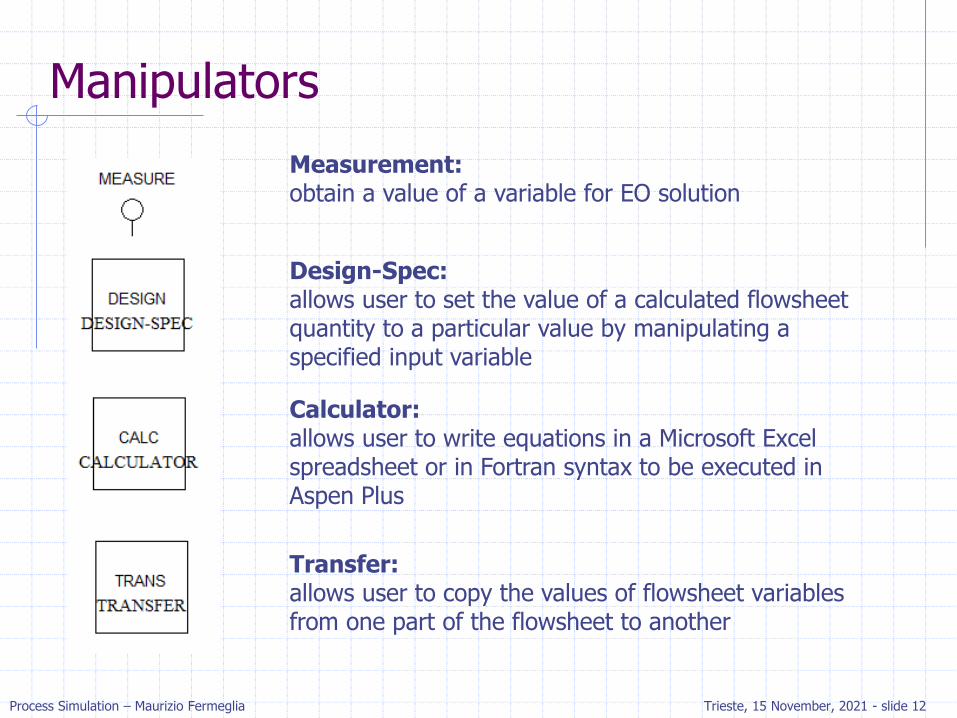
Manipulators
Measurement: obtain a value of a variable for EO solution
Design-Spec: allows user to set the value of a calculated flowsheet quantity to a particular value by manipulating a specified input variable
Calculator: allows user to write equations in a Microsoft Excel spreadsheet or in Fortran syntax to be executed in Aspen Plus
Transfer: allows user to copy the values of flowsheet variables from one part of the flowsheet to another

Process Simulation – Maurizio Fermeglia Trieste, 15 November, 2021 - slide 13
Solids
• Solids Models: Models for solid-solid interactions
• Solids handling, comminution and classifications models• Solids formation: crystallization, granulation and agglomeration
• Solid separator Models: Fluid-solid separation models with different techniques

Process Simulation – Maurizio Fermeglia Trieste, 15 November, 2021 - slide 14
User Models
Users Models can be added to Aspen Plus using: ◼ An Excel spreadsheet
◼ Fortran Interface
◼ Cape Open Interface (C++, VB)
◼ User models from Aspen Custom Modeler
Hierarchy: ◼ The hierarchy user model allows the user to group part of the flowsheet
into a sub-flowsheet, aiming to simplify the visualization of the whole process.

Heat Exchangers

Process Simulation – Maurizio Fermeglia Trieste, 15 November, 2021 - slide 16
Heater Model
Mixes multiple inlet streams to produce a single outlet stream at a specified thermodynamic state
Can be used to represent heaters as well as coolers
May be used to set the thermodynamic conditions of a stream, e.g. as a transition between different property methods
Vapor Fraction of 1 means dew point condition, 0 means bubble point

Process Simulation – Maurizio Fermeglia Trieste, 15 November, 2021 - slide 17
HeatX Model
Performs a mass and heat balance for both hot and cold streams
Calculation and Type settings select the mode of calculation performed by the model:◼ Shortcut: specified outlet condition for one of the streams
Design: calculates the required area using fixed values for Heat Transfer Coefficient minimizing the economical expenditures
Rating: determines if specified area is over or under surfaced
Simulation: determines outlet condition based on given area or heat transfer coefficient, performing calculation of heat transfer
Maximum Fouling: determines the maximum fouling
◼ Rigorous: use Exchanger Design and Rating (EDR) to design a new or rate an existing heat exchanger
◼ A Utility can be used for the hot or cold side instead of a process stream

Process Simulation – Maurizio Fermeglia Trieste, 15 November, 2021 - slide 18
HeatX Shortcut Results

Process Simulation – Maurizio Fermeglia Trieste, 15 November, 2021 - slide 19
HeatX Model as Interface to EDR
Information related to the heat exchanger configuration and geometry is entered through the individual programs on EDR Browser form

Process Simulation – Maurizio Fermeglia Trieste, 15 November, 2021 - slide 20
Sizing using EDR Sizing Console
Obtain results using the shortcut method, then move to rigorous approach
Select Shell&Tube, Kettle Reboiler, Thermosyphon, Air Cooled, or Plate to open EDR window for a rigorous design

Process Simulation – Maurizio Fermeglia Trieste, 15 November, 2021 - slide 21
Layout of EDR Sizing Console

Process Simulation – Maurizio Fermeglia Trieste, 15 November, 2021 - slide 22
Activated Analysis Dashboard
Activated Exchanger Analysis is an Activated Analysis Tool ◼ located on the Activated Analysis Dashboard,
◼ with Economics Analysis Tool (for economic aspects) and Energy Analysis Tools for energy optimization and savings.
Activated Exchanger Analysis enables the user to use EDR within Aspen +
Heat Exchangers are designed for process constraints while minimizing capital costs

Process Simulation – Maurizio Fermeglia Trieste, 15 November, 2021 - slide 23
Activated Analysis Workflow

Process Simulation – Maurizio Fermeglia Trieste, 15 November, 2021 - slide 24
Activated Analysys Results
Model status reports information for rigorous exchangers on the flowsheet◼ as geometry, setting plan,
surface area, …
Exchange Summary Table provides a list of all heat exchangers in the flowsheet◼ including simple and rigorous
models.
◼ provides a list of risks related to each equipment

Process Simulation – Maurizio Fermeglia Trieste, 15 November, 2021 - slide 25
MHeatX Model
MHeatX can be used to represent heat transfer between multiple hot and cold streams, as in LNG Exchanger◼ Detailed, rigorous internal zone analysis can be performed to determine
pinch points
MHeatX uses multiple Heater blocks and heat streams to enhance flowsheet convergence◼ Two-stream heat exchangers also can be modeled using MHeatX. No
connection with EDR, therefore it is not able to estimate geometry

Process Simulation – Maurizio Fermeglia Trieste, 15 November, 2021 - slide 26
Heat Exchanger Convergence Tips
If you get a temperature crossover message, check that streams are connected to the correct ports (HOT to HOT PORT and COLD to COLD PORT)
Run HeatX model in shortcut mode to rule out flow rate and physical property errors
If there are flash failures, switch to rating with an outlet temperature specification; it is more stable
Use zone analysis to diagnose problems:◼ Go to Home and click on Report. Then select the exchanger and produce a
txt with zone info
Run the hot and cold stream trough the MHeatX block and plot a composite heating/cooling curve to check for pinches and temperature crossovers
Change to vapor-liquid-liquid phases if there is a possibility of two-liquid phases

Process Simulation – Maurizio Fermeglia Trieste, 15 November, 2021 - slide 27
Heat Streams (Inlet)
Any number of inlet heat streams can be specified for a Heater.
Heater uses the sum of the inlet heat streams
When a heat stream is an inlet to a block, you only need one thermodynamic specification (e.g. pressure or pressure drop)

Process Simulation – Maurizio Fermeglia Trieste, 15 November, 2021 - slide 28
Heat Streams (Outlet)
One heat stream can be connected as outlet
It represents the net heat load from a Heater, i.e. the sum of the inlet heat streams minus the actual (calculated) heat duty
Heat streams flow in the direction that information (not heat) flows
Q > 0: cooling duty («take heat out»)Q < 0: heating duty («give heat back»)

Process Simulation – Maurizio Fermeglia Trieste, 15 November, 2021 - slide 29
HXFlux Model
Used to describe the Convective or Radiant heat transfer across a surface:◼ For convective heat transfer, the standard equation is:
Q=UA*LMTD
Co-current or Counter-current operation
No inlet or outlet material streams◼ reference to stream temperature or EO variables
Heat Duty may be specified in inlet heat stream or as reference to a heat stream

Process Simulation – Maurizio Fermeglia Trieste, 15 November, 2021 - slide 30
Utilities
A Utility is an option in Aspen Plus that can be used to calculate:◼ Energy usage
◼ Utility usage
◼ Energy/utility cost
◼ Greenhouse gas generation (optional)
It is possible to assign a utility to any block where Duty or Power is either specified or calculated (except MHeatX)

Process Simulation – Maurizio Fermeglia Trieste, 15 November, 2021 - slide 31
Utilities
To calculate the required utility flow for a given process, no physical changes to flowsheet are necessary:◼ From the Block Specification form, select the Utility sheet
◼ Choose the <New> from the Utility ID dropdown list
◼ Enter a name for the Utility or select a predefined one
◼ Click the Next button to go to Utilities folder
◼ Choose the Utility type from eight selections provided
◼ For Utility cost calculations, enter either the Purchase price or Energy price
◼ Set the Calculation option as Specify heating/cooling value, or Specify inlet/outlet conditions (set values on State Variables form) and supply related parameters
◼ Choose to calculate CO2 emissions if appropriate on the Carbon Tracking sheet
Process Simulation – Maurizio Fermeglia Trieste, 15 November, 2021 - slide 32
Utilities Demo
Modify the simulation of Exercise settling tank (water – chlorobenzene):◼ FLASH3 unit with water, CLBZ, CO2, N2 at 1 atm)
◼ Change the temperature of the settling tank to 15 °C (from 25°C).
◼ Create a new utility to cool down the mixture in the settling tank:
◼ Cooling water @ atmospheric pressure: Inlet Temperature 5°C
Outlet Temperature 10°C
How much cooling water is needed? ◼ Report in Models of Results Summary
◼ Perform a sensitivity study vary: inlet T of utility cooling water (from 5 to 9)
Tabulate: water flow rate in kg/h

Process Simulation – Maurizio Fermeglia Trieste, 15 November, 2021 - slide 33
Heat Curves
Heat Curves are used by design programs, including EDR, to evaluate exchanger behavior
Many unit operation models in A+ are able to calculate Heat Curves
Tables can be generated for various independent variables (typically duty or temperature) for any property that A+ can generate
These tables can be printed, plotted, or exported

Process Simulation – Maurizio Fermeglia Trieste, 15 November, 2021 - slide 34
Heat Curves
With an increase of the Heat flux:
◼ Enthalpy increases
◼ Density decreases

Process Simulation – Maurizio Fermeglia Trieste, 15 November, 2021 - slide 35
Heat Exchanger Demo
Compare the simulation of a heat exchanger that uses water to cool of 10 °C a hydrocarbon mixture using three methods:
- Two heaters connected with a Heat stream
- A Heater using Utility
- A rigorous HeatX

Process Simulation – Maurizio Fermeglia Trieste, 15 November, 2021 - slide 36
Data
Streams:◼ Hydrocarbon stream: 200 °C, 4 bar, 10000 kg/hr
◼ 50% wt benzene, 20% styrene, 20% ethylbenzene, 10% water
Cooling water: 20 °C, 10 bar, 60000 kg/hr
Property methods:◼ NRTL-RK for process side
◼ STEAMNBS for water side
Unit operations◼ For Heaters:
Hydrocarbon outlet stream degrees subcooling 10 °C
Zero pressure drop
Use property set HXDESIGN
Show the temperature of the streams on the flowsheet
Process Simulation – Maurizio Fermeglia Trieste, 15 November, 2021 - slide 37
Procedure
HeatX Block:◼ First run as a Shortcut model with:
Hydrocarbon stream exit degrees subcooling 10 °C
No pressure drop in either stream
◼ Next, run as a Rigorous Design type using EDR Sizing Console for a Shell&Tube heat exchanger: What is the calculated actual heat transfer area?
What is the cost of the heat exchanger?
What Operational Risk Type produce a warning?
Utility:◼ Use the cooling water with following specifications:
Inlet conditions: 20°C, 10 bar; Outlet conditions: 35 °C, 10 bar
Price: 0.0001 $/kg
◼ How much cooling water is required?
Plot Heat curves of Vapor mass flow and T versus Duty

Process Simulation – Maurizio Fermeglia Trieste, 15 November, 2021 - slide 38
Reviewing results
History file or Control Panel Messages contains any generated errors or warnings
Report: printable text file oh input data and simulation results
Model summary grid is a concise view of unit operation variables, design specification data, utilities, etc.
Accessed from Home Ribbon Summary group or Results Summary folder in Navigation Pane
Key input operation data is condensed into a single form◼ Input variables can me modified
◼ Data is organized by unit operations model type

Process Simulation – Maurizio Fermeglia Trieste, 15 November, 2021 - slide 39
Exporting results
Data in Aspen Plus Model Summary can be exported to MS Excel in two formats:◼ Not linked one-time transfer
◼ Linked to Aspen Plus simulation using Aspen Plus Simulation Workbook

Process Simulation – Maurizio Fermeglia Trieste, 15 November, 2021 - slide 40
Exporting results

Process Simulation – Maurizio Fermeglia Trieste, 15 November, 2021 - slide 41
Custom Tables
Custom Table allows the construction of customized tables of any Aspen Plus inputs or outputs
Custom Tables can be placed on the flowsheet:◼ Full Table view
◼ Table Icon, useful for minimizing flowsheet space. Double-click on it to display the table
Click to create a Custom Table
Custom Tables can be exported to Excel (static data or linked data)
Add variables by:
Copy and Paste from input/output forms into Custom Tables
Drag and Drop from input/output forms into Custom Tables