unit iv rendering - vidyarthiplus.com
TRANSCRIPT

CS2401-Computer Graphics Department of CSE & IT 2015-2016
St. Joseph’s College of Engineering/St.Joseph’s Institute of Technology 1 ISO 9001:2008
CS2401 COMPUTER GRAPHICS
UNIT I
2D PRIMITIVES
1. Define persistence, resolution.
Persistence is defined as the time it takes the emitted light from the screen to decay to one tenth of its
original intensity. The maximum number of points that can be displayed without overlap on a CRT is referred to as the resolution.
2. Define Aspect ratio. (AU MAY/JUNE 2013) Aspect ratio is the ratio of the vertical points to horizontal points necessary to produce equal length lines in both directions on the screen.
3. What is horizontal and vertical retrace?
The return to the left of the screen after refreshing each scan line is called as the horizontal retrace. Vertical retrace: At the end of each frame the electron beam returns to the top left corner of the screen to
the beginning the next frame.
4. What is interlaced refresh?
Each frame is refreshed using two passes. In the first pass, the beam sweeps across every other scan line from top to bottom. Then after the vertical retrace, the beam traces out the remaining scan lines.
5. What is a raster scan system?
In a raster scan system the electron beam is swept across the screen, one row at a time top to bottom. As the electron beam moves across each row, the beam intensity is turned on and off to create a pattern of
illuminated spots. Picture information is stored in a memory area called refresh buffer or frame buffer.
Most suited for scenes with subtle shading and color patterns.
6. What is a random scan system?
In random scan display unit, a CRT has the electron beam directed only to the parts of the screen where a
picture is to be drawn. This display is also called as vector displays. Picture definition is stored as asset of
line drawing commands in a memory referred to the refresh display file or display list or display program.
7. What is scan conversion and what is a cell array?
Digitizing a picture definition given in an application program into a set of pixel intensity values for
storage in the frame buffer by the display processor is called scan conversion. The cell array is a primitive that allow users to display an arbitrary shape defined as a two dimensional grid pattern.
8. What is the major difference between symmetrical DDA and simple DDA? (AU MAY/JUNE 2012)
Simple DDA Symmetric DDA
In simple DDA, m=Δx/eΔy is transformed to m=eΔx/eΔy where e, call it the increment factor,
is a positive real number.
In symmetric DDA, e is chosen such that though both the co-ordinates of the resultant points has to
be rounded off, it can be done so very efficiently,
thus quickly.
e is chosen as 1/max(|Δx|,|Δy|) such that one of the coordinate is integral and only the other
coordinate has to be rounded. i.e. P(i+1) =
P(i)+(1,Round(e*Δy)) here one coordinate is being incremented by 1 and the other by e*Δy
e is chosen as 1/2^n where 2^(n-1) <= max(|Δx|,|Δy|) < 2^n. In other words the length of
the line is taken to be 2^n aligned. The increments
for the two coordinates are e*Δx and e*Δy.
9. Digitize a line from (10,12) to (15,15) on a raster screen using Bresenham’s straight line
algorithm.(AU NOV/DEC 2013)
∆x=5, ∆y=3 Initial decision parameter
P0= 2 ∆y - ∆x
= 1 Increments for calculating successive
decision parameters are
2 ∆y = 6 2∆y - 2∆x = -4
Plot initial point (x0,y0) = (10,12)
K Pk (Xk+1,Yk+1)
0 1 (11,13)
1 -3 (12,13)
2 3 (13,14)
3 -1 (14,14)
4 5 (15,15)
10. List down any two attributes of lines. (AU MAY/JUNE 2014 & NOV/DEC 2014)
The basic attributes of a straight line segment are its:
www.vidyarthiplus.com
www.vidyarthiplus.com

CS2401-Computer Graphics Department of CSE & IT 2015-2016
St. Joseph’s College of Engineering/St.Joseph’s Institute of Technology 2 ISO 9001:2008
Type: solid, dashed and dotted lines.
Width: the thickness of the line is specified.
Color: a color index is included to provide color or intensity properties.
11. What are line caps?
The shape of the line ends are adjusted to give a better appearance by adding line caps.
Butt cap: obtained by adjusting the end positions of the component parallel lines so that the thick
line is displayed with square ends that is perpendicular to the line path.
Round cap: obtained by adding a filled semicircle to each butt cap.
Projecting square cap: extend the line and add butt caps that are positioned one-half of the line
width beyond the specified endpoints.
12. What are different methods of smoothly joining two line segments?
Miter joins: Accomplished by extending the outer boundaries of each of the two lines until they
meet.
Round join: produced by capping the connection between the two segments with a circular
boundary whose diameter is equal to the line width.
Bevel join: generated by displaying the line segments with butt caps and filling in the triangular
gap where the segments meet.
13. Write down the attributes of characters. (AU MAY/JUNE 2012 IT & MAY/JUNE 2014)
The appearance of displayed characters is controlled by attributes such as font, size, color and orientation. Attributes can be set both for entire character strings (text) and for individual characters defined as marker
symbols. The choice of font gives a particular design style. Characters can also be displayed as
underlined, in boldface, in italics and in outline or shadow styles.
14. Briefly explain about the unbundled attributes.
Unbundled attributes: how exactly the primitive is to be displayed is determined by its attribute setting.
These attributes are meant to be used with an output device capable of displaying primitives the way
specified.
15. Briefly explain about the bundled attributes.
Bundled attributes: when several kinds of output devices are available at a graphics installation, it is
convenient for a user to be able to say how attributes are to be interpreted on different o/p devices. This is accomplished by setting up tables for each output device that lists sets of attribute value that are to be
used on that device to display each primitive type. A particular set of attribute values for a primitive on
each o/p device is then chosen by specifying the appropriate table index. Attributes specified in this manner is called as bundled attribute.
16. Define aliasing.
Displayed primitives generated by the raster algorithms have a jagged, stair step appearance because the
sampling process digitizes coordinate points on an object to discrete integer pixel positions. This distortion of information due to low frequency sampling is called aliasing.
17. What is antialiasing?
Appearance of displayed raster lines by applying antialiasing methods that compensate for the under sampling process.
Nyquist sampling frequency: to avoid losing information, the sampling frequency to at least twice that of
the highest frequency occurring in the object. Fs=2*fmax.
Butt cap Round cap Projecting square cap.
www.vidyarthiplus.com
www.vidyarthiplus.com

CS2401-Computer Graphics Department of CSE & IT 2015-2016
St. Joseph’s College of Engineering/St.Joseph’s Institute of Technology 3 ISO 9001:2008
18. What is antialiasing by super sampling or post filtering?
This is a technique of sampling object characteristics at a high resolution and displaying results at a lower resolution.
19. What is antialiasing by area sampling or prefiltering?
An alternative to super sampling is to determine pixel intensity by calculating areas of overlap of each
pixel with the objects to be displayed .antialiasing by computing overlaps areas is referred to as area sampling or prefiltering.
20. What is antialiasing by pixel phasing?
Raster objects can be antialiased by shifting the display location of pixel areas. This is applied by ―micro positioning‖ the electron beam in relation to object geometry.
21. What are homogeneous co-ordinates? (AU MAY/JUNE 2012 IT)
To express any 2D transformation as a matrix multiplication, each Cartesian co-ordinate position (x, y) is
represented with the homogeneous coordinate triple (xh, yh, h) where x= and y= . Thus the general
homogeneous coordinate representation can also be written as (h.x, h.y, h). The homogeneous parameter h can be any nonzero value. A convenient choice is to set h=1. Each 2D position is then represented by
the homogeneous coordinates (x, y, 1).
22. What are the basic transformations? Translation : translation is applied to an object by repositioning it along a straight line path from one
coordinate location to another.
x1=x+Tx y1=y+Ty (Tx,Ty) – translation vector or shift vector Rotation: a two dimensional rotation is applied to an object by repositioning it along a circular path in the
xy plane.
P1=R.P
R= cosθ -sinθ sinθ cosθ θ- rotation angle
Scaling:a scaling transformation alters the size of an object . x1=x.Sx y1=y.Sy Sx and Sy are scaling factors.
23. What is uniform and differential scaling?
Uniform scaling: Sx and Sy are assigned the same value.
Differential scaling: unequal values for Sx and Sy.
24. Define shear
A transformation that distorts the shape of an object such that the transformed shape appears as if the
object is composed of internal layers that had been caused to slide over each other is called shear.
25. Define reflection.
A reflection is a transformation that produces a mirror image of an object.
By line y =0(x-axis) 1 0 0
transformation matrix = 0 -1 0
0 0 1
By the x axis
-1 0 0
transformation matrix = 0 1 0 0 0 1
26. Write down the shear transformation matrix. (AU NOV/DEC 2012)
A transformation that distorts the shape of an object such that the transformed shape appears as if the
object is composed of internal layers that had been caused to slide over each other is called shear. x-direction shear relative to x axis
www.vidyarthiplus.com
www.vidyarthiplus.com

CS2401-Computer Graphics Department of CSE & IT 2015-2016
St. Joseph’s College of Engineering/St.Joseph’s Institute of Technology 4 ISO 9001:2008
x-direction shear relative to other reference lines
y-direction shear relative to x=xref
27. Differentiate window and viewport. (AU NOV/DEC 2011)
Window Viewport
A window is a world coordinate area selected for display.
A viewport is an area on a display device to which the window is mapped.
The window defines what is to be viewed The viewport defines where it is to be displayed.
28. What is the rule of clipping? (AU MAY/JUNE 2012)
For the viewing transformation, we are needed to display only those picture parts that are within the window area. Everything outside the window is discarded. Clipping algorithms are applied in world co-
ordinates, so that only the contents of the window interior are mapped to device co-ordinates.
29. Define clipping. (AU NOV/DEC 2012 & MAY/JUNE 2014) Any procedure that identifies those portions of a picture that are either inside or outside of a specified
region of space is referred to as a clipping algorithm or clipping. The region against which an object is to
be clipped is called as the clip window.
30. How will you clip a point? (AU MAY/JUNE 2013)
Assuming that the clip window is a rectangle in standard position, we save a point P = (x,y) for display if
the following inequalities are satisfied:
xwmin <= x <= wxmax ywmin <= y <=ywmax
where the edges of the clip window [xwmin, xwmax, ywmin, ywmax ] can be either the world coordinate
window boundaries or viewport boundaries. If any one of these four inequalities is not satisfied, the point is clipped ( not saved for display ). For example , point clipping can be applied to scenes involving
explosions or sea foam that are modeled with particles ( points) distributed in some region of the scene.
31. List the different types of text clipping methods available. Give an example for text clipping. (AU
NOV/DEC 2013 & MAY/JUNE 2014) The different types of text clipping methods are
All –or-none string clipping.
All-or-none character clipping.
Clip-components of individual characters.
1)All or none string 2) All or none character clipping3) Clip components of individual characters
PART B
1. Write down and explain the Bresenham‘s line drawing algorithm with example. (AU MAY/JUNE 2012)
Algorithm -steps
www.vidyarthiplus.com
www.vidyarthiplus.com

CS2401-Computer Graphics Department of CSE & IT 2015-2016
St. Joseph’s College of Engineering/St.Joseph’s Institute of Technology 5 ISO 9001:2008
Start
Read the two end points of the line and assign the left end point to x0 ,y0
Load x0 ,y0 into the frame buffer (i.e) plot the first point
Compute dx,dy,2dy and 2dy-2dx and determine the decision parameter P0 as 2dy-dx At each xk , along the line starting at k = 0, perform the following test
If Pk < 0, the next point to plot is (xk+1 , yk ) and Pk+1 = Pk +2dy
Otherwise the next point to plot is (xk , yk+1 ) and Pk+1 = Pk +2dy- 2dx Repeat step 4 dx times
Stop
Example
www.vidyarthiplus.com
www.vidyarthiplus.com

CS2401-Computer Graphics Department of CSE & IT 2015-2016
St. Joseph’s College of Engineering/St.Joseph’s Institute of Technology 6 ISO 9001:2008
2. Explain about Bresenham‘s circle generating algorithm. (AU MAY/JUNE 2012)
Start
Input the radius r and the center (xc,yc) and obtain the first point on the circumference of a circle centered
on the origin as (x0,y0) = (0,r) Calculate the initial value of the decision parameter as P0 = 5/4 – r
At each xk position, starting at k = 0, perform the following test
If Pk < 0, the next point along the circle centered on (0,0) is (xk+1,yk) and Pk+1 = Pk +2xk+1+1 Otherwise, the next point along the circle is (xk+1,yk-1) and Pk+1 = Pk +2xk+1+1- 2yk+1 where 2x k+1 = 2x k + 2
and 2yk+1 = 2y k - 2
Determine symmetry points in the remaining seven octants Move each calculated pixel position (x,y) onto the circular path centered on (xc,yc) and plot the coordinate
value x = x+xc , y = y+ yc
Repeat steps 3 to 5 until x >= y
Stop
Example
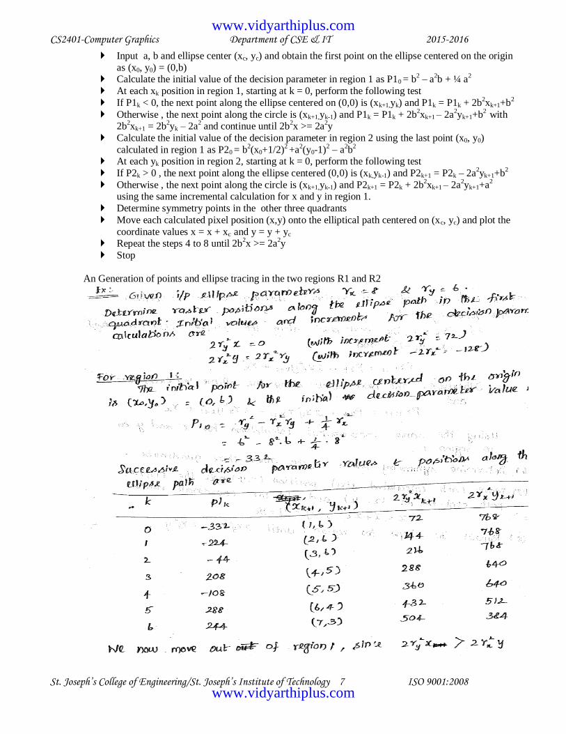
3. Explain the ellipse drawing algorithm with an example. (AU MAY/JUNE 2014 & NOV/DEC 2014) Algorithm-steps
Start
www.vidyarthiplus.com
www.vidyarthiplus.com
CS2401-Computer Graphics Department of CSE & IT 2015-2016
St. Joseph’s College of Engineering/St. Joseph’s Institute of Technology 7 ISO 9001:2008
Input a, b and ellipse center (xc, yc) and obtain the first point on the ellipse centered on the origin
as (x0, y0) = (0,b) Calculate the initial value of the decision parameter in region 1 as P10 = b
2 – a
2b + ¼ a
2
At each xk position in region 1, starting at k = 0, perform the following test
If P1k < 0, the next point along the ellipse centered on (0,0) is (xk+1,yk) and P1k = P1k + 2b2xk+1+b
2
Otherwise , the next point along the circle is (xk+1,yk-1) and P1k = P1k + 2b2xk+1 – 2a
2yk+1+b
2 with
2b2xk+1 = 2b
2yk – 2a
2 and continue until 2b
2x >= 2a
2y
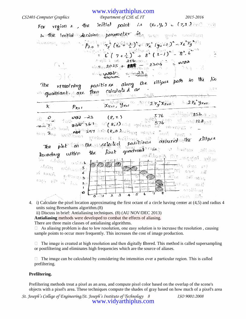
Calculate the initial value of the decision parameter in region 2 using the last point (x0, y0)
calculated in region 1 as P20 = b2(x0+1/2)
2 +a
2(y0-1)
2 – a
2b
2
At each yk position in region 2, starting at k = 0, perform the following test
If P2k > 0 , the next point along the ellipse centered (0,0) is (xk,yk-1) and P2k+1 = P2k – 2a2yk+1+b
2
Otherwise , the next point along the circle is (xk+1,yk-1) and P2k+1 = P2k + 2b2xk+1 – 2a
2yk+1+a
2
using the same incremental calculation for x and y in region 1.
Determine symmetry points in the other three quadrants
Move each calculated pixel position (x,y) onto the elliptical path centered on (xc, yc) and plot the
coordinate values x = x + xc and y = y + yc Repeat the steps 4 to 8 until 2b
2x >= 2a
2y
Stop
An Generation of points and ellipse tracing in the two regions R1 and R2
www.vidyarthiplus.com
www.vidyarthiplus.com
CS2401-Computer Graphics Department of CSE & IT 2015-2016
St. Joseph’s College of Engineering/St. Joseph’s Institute of Technology 8 ISO 9001:2008
4. i) Calculate the pixel location approximating the first octant of a circle having center at (4,5) and radius 4
units suing Bresenhams algorithm.(8)
ii) Discuss in brief: Antialiasing techniques. (8) (AU NOV/DEC 2013) Antialiasing methods were developed to combat the effects of aliasing.
There are three main classes of antialiasing algorithms.
As aliasing problem is due to low resolution, one easy solution is to increase the resolution , causing
sample points to occur more frequently. This increases the cost of image production.
The image is created at high resolution and then digitally filtered. This method is called supersampling
or postfiltering and eliminates high frequencies which are the source of aliases.
The image can be calculated by considering the intensities over a particular region. This is called
prefiltering.
Prefiltering.
Prefiltering methods treat a pixel as an area, and compute pixel color based on the overlap of the scene's objects with a pixel's area. These techniques compute the shades of gray based on how much of a pixel's area
www.vidyarthiplus.com
www.vidyarthiplus.com

CS2401-Computer Graphics Department of CSE & IT 2015-2016
St. Joseph’s College of Engineering/St. Joseph’s Institute of Technology 9 ISO 9001:2008
is covered by a object.
For example, a modification to Bresenham's algorithm was developed by Pitteway and Watkinson. In this algorithm, each pixel is given an intensity depending on the area of overlap of the pixel and the line. So, due
to the blurring effect along the line edges, the effect of antialiasing is not very prominent, although it still
exists.
Prefiltering thus amounts to sampling the shape of the object very densely within a pixel region. For shapes other than polygons, this can be very computationally intensive.
Postfiltering.
Supersampling or postfiltering is the process by which aliasing effects in graphics are reduced by increasing
the frequency of the sampling grid and then averaging the results down. This process means calculating a virtual image at a higher spatial resolution than the frame store resolution and then averaging down to the
final resolution. It is called postfiltering as the filtering is carried out after sampling.
There are two drawbacks to this method
The drawback is that there is a technical and economic limit for increasing the resolution of the
virtual image.
Since the frequency of images can extend to infinity, it just reduces aliasing by raising the Nyquist
limit - shift the effect of the frequency spectrum.
Supersampling is basically a three stage process.
A continuous image I(x,y) is sampled at n times the final resolution. The image is calculated at n
times the frame resolution. This is a virtual image.
The virtual image is then lowpass filtered
The filtered image is then resampled at the final frame resolution.
.
Algorithm for supersampling
To generate the origial image, we need to consider a region in the virtual image. The extent of that
region determines the regions involved in the lowpass operation. This process is called convolution.
After we obtain the virtual image which is at a higher resolution, the pixels of the final image are
located over superpixels in the virtual image. To calculate the value of the final image at (Si,Sj), we place the filter over the superimage and compute the sum of the filter weights and the surrounding
pixels. An adjacent pixel of the final image is calculated by moving the filter S superpixels to the
right. Thus the step size is same as the scale factor between the real and the virtual image.
Filters combine samples to compute a pixel's color. The weighted filter shown on the slide combines
nine samples taken from inside a pixel's boundary. Each sample is multiplied by its corresponding
weight and the products are summed to produce a weighted average, which is used as the pixel color.
In this filter, the center sample has the most influence. The other type of filter is an unweighted filter.
In an unweighted filter, each sample has equal influence in determining the pixel's color. In other words, an unweighted filter computes an unweighted average.
The spatial extent of the filter determines the cutoff frequency. The wider the filter, the lower is the
cutoff frequency and the more blurred is the image.
The options available in supersampling are
The value of S - scaling factor between the virtual and the real images.
The choice of the extents and the weights of the filter
www.vidyarthiplus.com
www.vidyarthiplus.com

CS2401-Computer Graphics Department of CSE & IT 2015-2016
St. Joseph’s College of Engineering/St. Joseph’s Institute of Technology 10 ISO 9001:2008
As far the first factor is concerned, higher the value, the better the result is going to be. The compromise to
be made is the high storage cost.
5. Explain the following: (AU NOV/DEC 2012)
a. Line drawing algorithm. (8)
DDA algorithm Step : 1
If the slope is less than or equal to 1 ,the unit x intervals Dx=1 and compute each successive y
values. Dx=1
m = Dy / Dx
m = ( y2-y1 ) / 1 m = ( yk+1 – yk ) /1
yk+1 = yk + m
subscript k takes integer values starting from 1,for the first point and increment by 1 until
the final end point is reached. m->any real numbers between 0 and 1
Calculate y values must be rounded to the nearest integer
Step : 2 If the slope is greater than 1 ,the roles of x any y at the unit y intervals Dy=1 and compute
each successive y values.
Dy=1
m= Dy / Dx
m= 1/ ( x2-x1 )
m = 1 / ( xk+1 – xk )
xk+1 = xk + ( 1 / m )
Step : 3 If the processing is reversed, the starting point at the right
Dx=-1
m= Dy / Dx
m = ( y2 – y1 ) / -1 yk+1 = yk - m
Iintervals Dy=1 and compute each successive y values.
Step : 4 Here, Dy=-1
m= Dy / Dx
m = -1 / ( x2 – x1 ) m = -1 / ( xk+1 – xk )
xk+1 = xk + ( 1 / m )
b. Line clipping algorithm. (8)
Liang-Barsky line clipping
To compute the final line segment:
1. A line parallel to a clipping window edge has for that boundary.
2. If for that , , the line is completely outside and can be eliminated.
3. When the line proceeds outside to inside the clip window and when , the line proceeds
inside to outside.
www.vidyarthiplus.com
www.vidyarthiplus.com

CS2401-Computer Graphics Department of CSE & IT 2015-2016
St. Joseph’s College of Engineering/St. Joseph’s Institute of Technology 11 ISO 9001:2008
4. For nonzero , gives the intersection point.
5. For each line, calculate and . For , look at boundaries for which (i.e. outside to inside).
Take to be the largest among . For , look at boundaries for which (i.e. inside to outside).
Take to be the minimum of . If , the line is outside and therefore rejected.
6. With suitable examples, explain the following
a. Rotational transformations. (8)
Reposition an object along the circular path in the XY plane To generate rotation specify
rotational angle Θ
rotation point/pivot point + ve values for Θ define anticlockwise rotation
- ve values for Θ define clockwise rotation
Transformation equation: x
I = r Cos( Ф+Θ) = r Cos Ф Cos Θ – r Sin Ф Sin Θ
yI = r Sin( Ф + Θ) = r Cos Ф Sin Θ + r Sin Ф Cos Θ
but x = r Cos Ф
y = r Sin Ф
So, x
I = x Cos Θ – y Sin Θ
yI
= x Sin Θ + y Cos Θ
Column vector rep.
PI = R.P
b. Curve clipping algorithm. (8)
The bounding rectangle for a curved object can be used first to test for overlap with a rectangular clip window (we can use polygon clipping)
Case 1
If the bounding rectangle for the object is completely inside the window, we save the object.
Case 2
If the rectangle is determined to be completely outside the window, we discard the object
Case 3 If the two regions overlap, we will need to solve the simultaneous line-curve equations to obtain the
clipping intersection points.
Circle clipping If XC + R < XLEFT Then the circle is discarded .
-No need for bounding triangle
If XC - R > Xright Then the circle is discarded If YC - R >Ytop Then the circle is discarded
If YC +R <Ybottom Then the circle is discarded
www.vidyarthiplus.com
www.vidyarthiplus.com
CS2401-Computer Graphics Department of CSE & IT 2015-2016
St. Joseph’s College of Engineering/St. Joseph’s Institute of Technology 12 ISO 9001:2008
If all the four previous conditions are false then the circle is saved
Intersection conditions:
With right edge:
Xc+R>Xright With left edge:
Xc-R<Xleft
With top edge : Yc+R>Ytop
With bottom edge:
Yc-R<Ybottom
Getting intersection points :
Example : The intersection with the right edge
Simply Cos α = (Xright-Xc )/R
Get α
y=R sin α
the segment from angle 0 to angle α is discarded
the segment from angle α to angle 360-α is considered
the segment from angle 360-α to angle 360 is discarded
7. Write a detailed note on the basic two dimensional transformations. Transformations-definition and types of transformations
Transformation:
alter the coordinate description of the objects. Basic geometric transformation:
Translation
Rotation
Scaling
Additional transformation:
Reflection
Shear
Translation
Moves the object without deformation Points are translated by the same amount
Translation equation:
xI = x + tx y
I = y + ty
Matrix equation:
PI = P + T
Rotation: Reposition an object along the circular path in the XY plane
Transformation equation:
xI = r Cos( Ф+Θ) = r Cos Ф Cos Θ – r Sin Ф Sin Θ
yI = r Sin( Ф + Θ) = r Cos Ф Sin Θ + r Sin Ф Cos Θ
but
x = r Cos Ф
y = r Sin Ф So,
xI
= x Cos Θ – y Sin Θ
www.vidyarthiplus.com
www.vidyarthiplus.com

CS2401-Computer Graphics Department of CSE & IT 2015-2016
St. Joseph’s College of Engineering/St. Joseph’s Institute of Technology 13 ISO 9001:2008
yI
= x Sin Θ + y Cos Θ
Column vector rep. P
I = R.P
Scaling:
alters the size of the object
coordinate values of the vertex is multiplied by scaling factors Sx & Sy x
I = x . Sx
yI = y . Sy
Reflection produces mirror image
obtained by rotating the object 180 degrees about the reflection axis.
Shear distorts the shape of an object.
can be with respect to both axis
8. i)A polygon has four vertices located at A(20,10) B(60,10) C(60,30) D (20,30). Calculate the vertices after applying a transformation matrix to double the size of polygon with point A located on the same
place.(8)
Transformations-definition and types of transformations Transformation:
alter the coordinate description of the objects.
Basic geometric transformation:
Translation
Rotation
Scaling
Additional transformation:
Reflection
Shear
Scaling-definition-equations-diagram-matrix representation
Scaling: alters the size of the object
coordinate values of the vertex is multiplied by scaling factors Sx & Sy
xI = x . Sx
yI = y . Sy
Apply the equation to each point A(20,10) B(60,10) C(60,30) D (20,30) Fixed point scaling procedure must be used
A(20,10) is used as the fixed point and the transformed values are calculated
ii) The reflection along the line y = x is equivalent to the reflection along the X axis followed by counter
clockwise rotation by Φ.(8) (AU NOV/DEC 2013)
Transformations-definition and types of transformations Transformation:
alter the coordinate description of the objects.
Basic geometric transformation:
Translation
Rotation
Scaling
Additional transformation:
Reflection
www.vidyarthiplus.com
www.vidyarthiplus.com

CS2401-Computer Graphics Department of CSE & IT 2015-2016
St. Joseph’s College of Engineering/St. Joseph’s Institute of Technology 14 ISO 9001:2008
Shear
Reflection-definition-equations-diagram-matrix representation
Reflection
produces mirror image
obtained by rotating the object 180 degrees about the reflection axis.
Rotation-definition-equations-diagram-matrix representation The reflection matrix is solved for the angle Φ
9. i) Explain two dimensional Translation and Scaling with an example.(8)
Transformations-definition and types of transformations
Translation Moves the object without deformation
Points are translated by the same amount
Translation equation:
xI = x + tx y
I = y + ty
Matrix equation:
PI = P + T
Scaling-definition-equations-diagram-matrix representation
Scaling:
alters the size of the object
coordinate values of the vertex is multiplied by scaling factors Sx & Sy x
I = x . Sx
yI = y . Sy
ii) Obtain a transformation matrix for rotating an object about a specific pivot point.(8) (AU NOV/DEC 2013)
To rotate the object about any selected point (xr ,yr )
perform, Translation
Rotation
Translation ( inverse translation)
in sequence
Translation
Moves the object without deformation
Points are translated by the same amount Translation equation:
xI = x + tx y
I = y + ty
Matrix equation: P
I = P + T
Rotation:
Reposition an object along the circular path in the XY plane Transformation equation:
xI = r Cos( Ф+Θ) = r Cos Ф Cos Θ – r Sin Ф Sin Θ
yI = r Sin( Ф + Θ) = r Cos Ф Sin Θ + r Sin Ф Cos Θ
but
x = r Cos Ф
y = r Sin Ф So,
xI
= x Cos Θ – y Sin Θ
yI
= x Sin Θ + y Cos Θ
www.vidyarthiplus.com
www.vidyarthiplus.com

CS2401-Computer Graphics Department of CSE & IT 2015-2016
St. Joseph’s College of Engineering/St. Joseph’s Institute of Technology 15 ISO 9001:2008
Column vector rep.
PI = R.P
Inverse Translation
Points are translated by the same amount
Translation equation:
x = xI - tx y = y
I - ty
Matrix equation:
P = PI - T
10. Explain briefly the line clipping algorithm with an example. (AU NOV/DEC 2014 )
Basic concept of Cohen-Sutherland Region codes
Bit 1 – left
Bit 2 – right
Bit 3 – below Bit 4 – above
If the point is in clipping rectangle then the region code is 0000
A value of 1 in any position indicates the point is in that relative position
Assignment of Binary region codes
Bit 1 is set to 1 if x < xwmin Bit 2 is set to 1 if x > xwmax
Bit 3 is set to 1 if y < ywmin
Bit 4 is set to 1 if y > ywmax
Calculation of intersection points with the clip window
Accept the lines whose both endpoints are having the region code 0000
Reject the lines whose endpoints have a 1 in the same bit position in the region code Lines that cannot be identified as completely inside or outside a clip window are checked for
intersection with window boundaries
Intersection with clipping boundary can be calculated using the slope intercept form of the line
equation. The intersection point with the vertical boundary is
y = y1 + m (x – x1 )
The intersection point with the horizontal boundary is x = x1 + (y – y1) / m
Example
www.vidyarthiplus.com
www.vidyarthiplus.com

CS2401-Computer Graphics Department of CSE & IT 2015-2016
St. Joseph’s College of Engineering/St. Joseph’s Institute of Technology 16 ISO 9001:2008
11. Explain in detail about window to viewport coordinate transformation.
The viewing pipeline
Mapping a part of a world coordinate scene to device coordinates
2D viewing transformation pipeline
MC → WC → VC →NVC →DC
Window and Viewport-definition
Viewing transformation-window to viewport transformation-windowing transformation The mapping of a point at position P(xw , yw ) in window to viewport is given by
xv = xvmin + (xw – xwmin ).sx
yv = yvmin + (yw – ywmin ).sy
www.vidyarthiplus.com
www.vidyarthiplus.com

CS2401-Computer Graphics Department of CSE & IT 2015-2016
St. Joseph’s College of Engineering/St. Joseph’s Institute of Technology 17 ISO 9001:2008
where
sx = xvmax – xvmin / xwmax – xwmin sy = yvmax – yvmin / ywmax – ywmin
12. Explain in detail Sutherland-Hodgeman polygon clipping algorithm with example. (AU MAY/JUNE
2012 IT) Sutherland Hodgeman Polygon Clipping
performed by processing polygon vertices against each clip rectangle boundary
Processing cases 1. First vertex is outside , Second is inside
add second vertex & intersection point of polygon edge with window boundary to o/p vertex list
2. If both vertices are inside add the second vertex to o/p vertex list
3. If the first vertex is inside ,second is outside
save the edge intersection point with window boundary to o/p vertex list
4. If both vertices are outside add nothing to o/p vertex list
UNIT II
3D CONCEPTS
1. What are the two types of projections? Parallel projection: coordinate positions are transformed to the view plane along parallel lines.
Perspective projection: object positions are transformed to the view plane along lines that converge to a
point called projection reference point.
2. Differentiate parallel projection from perspective projection. (AU NOV/DEC 2014)
Parallel Projection Perspective Projection
In parallel projection, coordinate positions are
transformed to the view plane along parallel lines.
In perspective projection, object positions are
transformed to the view plane along lines that
converge to a point called projection reference point. Or center of projection
Preserves the relative proportions of objects. Produce realistic views but does not preserve
relative proportions.
Used in drafting to produce scale drawings of 3D objects.
Projections of distant objects are smaller than the projections of objects of the same size that are
closer to the projection plane.
3. Differentiate oblique and orthographic parallel projections. (AU MAY/JUNE 2012 IT &NOV/DEC
2012)
Orthographic Parallel Projection Oblique Parallel projection
Projection is perpendicular to the view plane. Projection is not perpendicular to the view plane
Used to produce front, side and top views of object
called as elevations
An oblique projection vector is specified with two
angles, and .
4. Give the single-point perspective projection transformation matrix when projectors are placed on
the z-axis. (AU NOV/DEC 2013)
Xn 1 0 0 0 x
Yn = 0 1 0 0 y
Zn 0 0 -Zvp/dp Zvp(Zprp/dp) z h 0 0 -1/dp (Zprp/dp) 1
5. What are the two types of parallel projection?
Orthographic parallel projection: projection is perpendicular to the view plane. Oblique parallel projection: projection is not perpendicular to the view plane.
6. Explain about axonometric projection.
www.vidyarthiplus.com
www.vidyarthiplus.com

CS2401-Computer Graphics Department of CSE & IT 2015-2016
St. Joseph’s College of Engineering/St. Joseph’s Institute of Technology 18 ISO 9001:2008
Orthogonal projections that display more than one face of an object are axonometric projection.
7. Explain about isometric projection. Isometric projection is obtained by aligning the projection plane so that it intersects each coordinate axis
in which the object is defined at the same distance from the origin.
8. Explain about cavalier projections.
Point (x,y,z) is projected tp position (xp,yp) on the view plane. The projection line from (x,y,z) and (xp,yp) makes and angle α with the line on the projection plane that joins(xp,yp) and (x,y). when α = 45
the views obtained are cavalier projectins. All lines perpendicu;ar to the projection plane are projected
with no change in length.
9. What are the representation schemes for solid objects?
Boundary representations: they describe a 3D object as a set of surfaces that separate the object interior
from environment. Example: polygon facets Space partitioning representations: they are used to describe interior properties, by partitioning the spatial region containing an object into a set of small, non-
overlapping, contiguous solids. Example: octree
10. Define quadric surfaces. (AU NOV/DEC 2011)
Quadric surfaces are described with second degree equations (quadrics). They include sphere, ellipsoids, tori, paraboloids and hyperboloids. Spheres and ellipsoids are common elements of graphic scenes, they
are often available in graphics packages from which more complex objects can be constructed.
11. What is an ellipsoid? An ellipsoid surface can be described as an extension of a spherical surface, where the radii in three
mutually perpendicular directions can have different values. The parametric representation for ellipsoid of
latitude angle and longitude angle is x = rxcoscos, -/2 ≤ ≤ /2, y= rycos sin, - ≤ ≤ and
z=rz sin
12. What are blobby objects?
Some objects do not maintain a fixed shape, but change their surface characteristics in certain motions or when in proximity with other objects. These objects are referred to as blobby objects, since their shapes
show a certain degree of fluidness.
13. What are splines? (AU NOV/DEC 2011, NOV/DEC 2012 MAY/JUNE 2014& NOV/DEC 2014)
The term spline is a flexible strip used to produce a smooth curve through a designated set of points. In computer graphics, the term spline curve refers to any composite curve formed with polynomial sections
satisfying specified continuity conditions at the boundary of the pieces.
14. How to generate a spline curve? A spline curve is specified by giving a set of coordinate positions called as control points. These control
points are then fitted with piece wise continuous parametric polynomial functions in one of the two ways.
When polynomial sections are fitted so that the curve passes through each control point, the resulting
curve is said to interpolate the set of control points. When the polynomials are fitted to the general control point path without necessarily passing through any control point the resulting curve is said to
approximate the set control points.
15. What are called control points? The spline curve is specified by giving a set of coordinate positions, called control points, which indicates
the general shape of the curve.
16. When is the curve said to interpolate the set of control points? When polynomial sections are fitted so that the curve passes through each control point, the resulting
curve is said to interpolate the set of control points.
17. When is the curve said to approximate the set of control points?
When the polynomials are fitted to the general control-point path without necessarily passing through any control point, the resulting curve is said to approximate the set of control points.
18. What is called a convex hull?
The convex polygon boundary that encloses a set of control points is called the convex hull.
19. Explain about Bezier curves.
This is a spline approximation method. A beizer curve section can be fitted to any number of control
points. The number of control points to be approximated and their relative position determine the degree
www.vidyarthiplus.com
www.vidyarthiplus.com
CS2401-Computer Graphics Department of CSE & IT 2015-2016
St. Joseph’s College of Engineering/St. Joseph’s Institute of Technology 19 ISO 9001:2008
of the Beizer polynomial. As with the interpolation splines , a beizer curve can be specified with
boundary conditions, with a characterization matrix , or with blending functions.
20. Give the general expression of Bezier Bernstein polynomial. (AU NOV/DEC 2013)
Bezier Bernstein polynomial
BEZk,n (u) = C (n,k) u k (1-u)
n-k
Where C(n,k) is the binomial coefficient
21. What are the advantages of B spline over Bezier curve? (AU MAY/JUNE 2013)
B-splines have two advantages over Bezier splines:
i. The degree of a B-spline polynomial can be set independently of the number of control points and
ii. B-splines allow local control over the shape of a spline curve or surface.
22. Explain about sweep representations. Sweep representations are useful for constructing three- dimensional objects that possess translational,
rotational or other symmetries. One can represent such objects by specifying a 2D shape and a sweep that
moves the shape through a region of space. A set of 2D primitives ,such as circle and rectangles, can be
provided for sweep representations as menu options.
23. What are the various 3D transformations?
The various 3D transformations are translation, reflection, scaling, rotation and shearing.
24. What is shear transformation? (AU MAY/JUNE 2012 IT) Shearing transformations can be used to modify object shapes. They are also used in 3D viewing for
obtaining general projection transformation. A z-axis 3D shear:
1 0 a 0 SHZ = 0 1 b 0
0 0 1 0
0 0 0 1
Parameters a and b can be assigned any real value.
25. Define viewing. (AU MAY/JUNE 2012 & MAY/JUNE 2014)
Viewing in 3D have more parameters to select when specifying how a 3D scene is to be mapped to a
display device. The scene description must be processed through the viewing coordinate transformation and projection routines that transform the 3D viewing coordinate into 2D device coordinates.
26. Mention some surface detection methods.
Back-face detection, depth-buffer method, A-buffer method, scan-line method, depth-sorting method,
BSP-tree method, area subdivision, octree method, ray casting.
27. What is ray casting?
Ray casting methods are commonly used to implement constructive solid geometry operations when
objects are described with boundary representations. Ray casting is applied by constructing composite objects in world coordinates with the xy plane corresponding to the pixel plane of a video monitor. This
plane is referred to as ―firing plane‖, since each pixel emits a ray through the objects that are combined.
Then the surface intersections along each ray path, and they are sorted according to the distance from the firing plane. The surface limits for the composite objects are determined by specified set operations.
28. Define Octree.
Hierarchical tree structures called octrees are used to represent solid objects in some graphics system. The
tree structure is organized so that each node corresponds to a region of 3D space. This representation for solids takes advantage of spatial coherence to reduce storage requirements for 3D objects.
PART B
1. Differentiate parallel and perspective projections and derive their projection matrices. (AU NOV/DEC 2011, MAY/JUNE 2012 IT, NOV/DEC 2012 & MAY/JUNE 2014)
• Parallel projections:
– no shortening due to distance – several kinds, depending on orientation:
• isometric, cavalier,…
• Perspective projections:
– shortening of objects in the distance
www.vidyarthiplus.com
www.vidyarthiplus.com

CS2401-Computer Graphics Department of CSE & IT 2015-2016
St. Joseph’s College of Engineering/St. Joseph’s Institute of Technology 20 ISO 9001:2008
– several kind, depending on orientation:
• one, two, three vanishing points Parallel Projection Matrix
• Parallel projection onto z=0 plane:
x’=x, y’=y, w’=w
Matrix for this projection:
Perspective Projection Matrix
Projection onto plane z=0, with center of projection at z=-d:
Perspective projections pros and cons: Size varies inversely with distance - looks realistic – Distance and angles are not (in general) preserved –
Parallel lines do not (in general) remain parallel
Parallel projection pros and cons:
Less realistic looking + Good for exact measurements + Parallel lines remain parallel – Angles not (in
general) preserved
Parallel projections
For parallel projections, we specify a direction of projection (DOP) instead of a COP. There are two types of
parallel projections: w Orthographic projection — DOP perpendicular to PP w Oblique projection — DOP not perpendicular to PP There are two especially useful kinds of oblique projections: w Cavalier projection •
DOP makes 45° angle with PP • Does not foreshorten lines perpendicular to PP w Cabinet projection • DOP
makes 63.4° angle with PP • Foreshortens lines perpendicular to PP by onehalf
Perspective in the graphic arts is an approximate representation, on a flat surface (such as paper), of an
image as it is seen by the eye. The two most characteristic features of perspective are that objects are smaller
as their distance from the observer increases; and that they are foreshortened, meaning that an object's dimensions along the line of sight are shorter than its dimensions across the line of sight.
2. Discuss the 3D object representations in detail. (AU NOV/DEC 2014)
Polygon surfaces-polygon tables-plane equations-polygon meshes
Object descriptions are stored as sets of surface polygons The surfaces are described with linear equations
Polygon table
www.vidyarthiplus.com
www.vidyarthiplus.com

CS2401-Computer Graphics Department of CSE & IT 2015-2016
St. Joseph’s College of Engineering/St. Joseph’s Institute of Technology 21 ISO 9001:2008
data is placed into the polygon table for processing
Polygon data table can be organised into two groups geometric table
attribute table
Quadric surfaces-sphere-ellipsoid-torus
Described with second degree eqns. Ex. Sphere,ellipsoids,tori,paraboloids,hyperboloids
Sphere
A spherical surface with radius ‗r‘ centered on the coordinate origin is defined as a set of points(x,y,z) that satisfy the equation
x2 + y
2 + z
2 = r
2
In parametric form, x = r CosΦCosΘ
y = r Cos ΦSinΘ
z = r Sin Φ
Blobby objects-definition and example Don‘t maintain a fixed shape
Change surface characteristics in certain motions
Ex. Water droplet, Molecular structures f(x,y,z) = Σk b ke
-ak r
k2 - T = 0
r = √x2 +
y2 + z
2
T =some threshold
a,b used to adjust the amount of bloobiness.
Spline-representation-interpolation
it is a composite curve formed with polynomial pieces satisfying a specified continuity conditions at the
boundary of the pieces Bezier curves
can be fitted to any no. of control points
degree of bezier polynomial is determined by the number of control points and their relative position Bezier curve is specified by
Boundary conditions
Characterising matrix
Blending function
3. How are polygon surfaces represented in 3D?
Polygon tables-Basic concept Polygon table
• data is placed into the polygon table for processing
• Polygon data table can be organised into two groups
geometric table
attribute table
Storing geometric data
To store geometric data three lists are created Vertex table – contains coordinate values for each vertex
Edge table – contains pointers back into the vertex table
Polygon table – contains pointers back into the edge table Advantages of three table
efficient display of objects
For faster info. Extraction
expand edge table to include forward pointers to the polygon table Plane Equation
www.vidyarthiplus.com
www.vidyarthiplus.com

CS2401-Computer Graphics Department of CSE & IT 2015-2016
St. Joseph’s College of Engineering/St. Joseph’s Institute of Technology 22 ISO 9001:2008
Ax + By + Cz + D = 0
eqn. is solved by Cramer‘s rule Identification of points
• if Ax + By + Cz + D < 0 ,the points (x,y,z) is inside the surface
• if Ax + By + Cz + D > 0 ,the points (x,y,z) is outside the surface
4. Write notes on quadric surfaces. (AU NOV/DEC 2012) Quadric surfaces-definition
Described with second degree eqns.
Ex. Sphere,ellipsoids,tori,paraboloids,hyperboloids Sphere-definition-equations-diagram
Sphere
A spherical surface with radius ‗r‘ centered on the coordinate origin is defined as a set of
points(x,y,z) that satisfy the equation x
2 + y
2 + z
2 = r
2
In parametric form,
x = r CosΦCosΘ y = r Cos ΦSinΘ
z = r Sin Φ
Ellipsoid-definition-equations-diagram
Ellipsoid
Extension of spherical surface ,where the radii in three mutually perpendicular directions have
different values (x/rx)
2 + (y/ry)
2 + (z/rz)
2 = 1
5. i) A cube has its vertices located at A(0,0,10) B(10,0,10) C (10,10,10) D(0,10,10) E(90,0,0) F(10,0,0) G(10,10,0) H(0,10,0). The Y axis is vertical and Z axis is oriented towards the viewer. The cube is being
viewed from point (0,20,80). Calculate the perspective view of the cube on XY plane.(8)
Perspective projections
Definition Example with diagram
Derivation and projection matrix
Apply for the values A(0,0,10) B(10,0,10) C (10,10,10) D(0,10,10) E(90,0,0) F(10,0,0) G(10,10,0) H(0,10,0)
ii) Discuss on the various visualization techniques in detail. (8) (AU NOV/DEC 2013 & MAY/JUNE 2014)
Visual representation for scalar fields
Visual representation for vector fields
Visual representation for tensor fields Visual representation for multivariate data fields
6. With suitable examples, explain all 3D transformations. (AU NOV/DEC 2011, MAY/JUNE 2012 IT,
NOV/DEC 2012, MAY/JUNE 2012 & MAY/JUNE 2014)
Transformation-definition and types
Translation-definition-equations-diagram-matrix representation
Translation
PI = T .P
xI = x + tx
yI = y + ty
zI = z + tz
www.vidyarthiplus.com
www.vidyarthiplus.com
CS2401-Computer Graphics Department of CSE & IT 2015-2016
St. Joseph’s College of Engineering/St. Joseph’s Institute of Technology 23 ISO 9001:2008
Inverse translation
- obtained by negating translation distances Rotation-definition-equations-diagram-matrix representation
Rotation
To perform rotation we need,
An axis Rotation angle
+ve rotation angles produce counter clockwise rotation
-ve rotation angles produce clockwise rotation Coordinate axis rotation Z-axis, Y-axis and X-axis
Z axis rotation
xI = xCosΘ – ySinΘ
yI = xSinΘ + yCosΘ
zI = z
PI
= Rz(Θ).P
Scaling Reflection Shearing -definition
Scaling:
alters the size of the object
coordinate values of the vertex is multiplied by scaling factors Sx & Sy x
I = x . Sx
yI = y . Sy
Reflection produces mirror image
obtained by rotating the object 180 degrees about the reflection axis.
Shear
distorts the shape of an object. can be with respect to both axis
Reflection-definition-equations-diagram-matrix representation Shearing-definition-equations-diagram-matrix representation
7. i) Calculate the new coordinates of a block rotated about x axis by an angle of = 30 degrees. The original
coordinates of the block are given relative to the global xyz axis system. (8) A(1,1,2) B(2,1,2) C(2,2,2) D(1,2,2) E(1,1,1) F(2,1,1) G(2,2,1) H(1,2,1)
Transformation-definition and types
Rotation-definition-equations-diagram-matrix representation Apply the rotation equations for the set of vertices A(1,1,2) B(2,1,2) C(2,2,2) D(1,2,2) E(1,1,1)
F(2,1,1) G(2,2,1) H(1,2,1)
ii) Discuss on Area subdivision method of hidden surface identification algorithms.(8) (AU NOV/DEC
2013)
- Successively divide the total viewing area into smaller and smaller rectangles until each small
area is the projection of part of a single visible surface or no surface at all Types of relationships b/w a surface & a specified area boundary
Surrounding surface
Overlapping surface Inside surface
Outside surface
Tests performed to determine the subdivision of an area All surfaces are outside surfaces with respect to the area
Only one inside overlapping or surrounding surface is in the area
A surrounding surface obscures all other surfaces within the area boundaries
If any one of these tests / conditions is true the specified area is not subdivided
www.vidyarthiplus.com
www.vidyarthiplus.com

CS2401-Computer Graphics Department of CSE & IT 2015-2016
St. Joseph’s College of Engineering/St. Joseph’s Institute of Technology 24 ISO 9001:2008
8. Write notes on 3D viewing. (AU NOV/DEC 2012) Viewing – transfers positions from world coordinate plane to pixels positions in the plane of the
output device
Viewing pipeline:
MC MT WC VT VC PT PC WT DC Transformation from world to viewing coordinates:
sequences
Translate view reference point to the origin of world coordinate system
Apply rotation to align xv , yv , zv axes with the world xw ,yw ,zw axes
9. Discuss the visible surface detection methods in detail. (AU MAY/JUNE 2014 & NOV/DEC 2014)
Back face detection
A point (x,y,z) is inside a polygon surface with plane parameters A,B,C and D if Ax+By+Cz+D < 0
When an inside point is along the line of sight to the surface , the polygon must be a back-face
Conditions for back face:
A polygon is a back-face if V.N > 0
Depth buffer method
Steps 1. Initialize the depth buffer and refresh buffer so that for all the buffer positions (x,y) depth(x,y) =
0 , refresh(x,y) = I backgnd
2. For each position on each polygon surface listed on the polygon table calculate the depth value and compare the depth vaslue to the previously stored values in the depth buffer to determine visibility
Let the calculated depth be Z for each position (x,y)
If Z > depth(x,y) , then set ) depth(x,y) = Z , refresh(x,y) = Isurf (x,y)
Scan-line method-concept-example-diagram
Extension of scan line algorithm for filling polygon interiors
All polygon surfaces intersecting the scan lines are examined
Depth calculations are made for each overlapping surface across every scan line to determine the
nearest surface to the view plane
After the visible surface is determined the intensity value for the position is entered into the
refresh buffer
Depth-sorting method
Steps:
Surfaces are ordered according to the largest Z value Surface S with greatest depth is compared with other surfaces to determine whether there are any overlaps
in depth
If no depth overlap occurs , S is scan converted
This process is repeated for the next surface as long as no overlap occurs If depth overlaps occurred additional comparisons are used to determine whether reordering of surfaces
are needed or not
Ray casting method - it is a variation of depth buffer method
- process pixels one at a time and calculate depths for all surfaces along the projection path to that
pixel
Wireframe method visible edges are displayed and hidden edges are either eliminated or displayed differently from the
visible edges .Procedures for determining visibility of object edges are referred to as wireframe
visibility methods / visible line detection methods / hidden line detection methods
www.vidyarthiplus.com
www.vidyarthiplus.com

CS2401-Computer Graphics Department of CSE & IT 2015-2016
St. Joseph’s College of Engineering/St. Joseph’s Institute of Technology 25 ISO 9001:2008
10. i) Determine the blending function for Uniform periodic B spline curve for n=4 d=4. (8) B-spline definition
Equation for B-spline Uniform periodic function
Substitute the values n=4 and d=4
ii) Explain any one visible surface identification algorithm. (8) (AU MAY/JUNE 2013)
Depth buffer method
Depth buffer method Steps
3. Initialize the depth buffer and refresh buffer so that for all the buffer positions (x,y) depth(x,y) =
0 , refresh(x,y) = I backgnd 4. For each position on each polygon surface listed on the polygon table calculate the depth value
and compare the depth vaslue to the previously stored values in the depth buffer to determine visibility
Let the calculated depth be Z for each position (x,y)
If Z > depth(x,y) , then set ) depth(x,y) = Z , refresh(x,y) = Isurf (x,y)
11. Explain a method to rotate a 3D object above an axis that is not parallel to the coordinate axis with a neat block diagram and derive the transformation matrix for the same. (AU MAY/JUNE 2013)
Perform Translation (make rotation axis passes through coordinate origin)
Rotation (make rotation axis coincide with one of the coordinate axes)
Specified rotation
Inverse rotation Inverse translation
UNIT III
GRAPHICS PROGRAMMING
1. What is a color model?
A color model is a method for explaining the properties or behavior of color within some particular
context. Example: XYZ model, RGB model.
2. Define intensity of light, brightness and hue. Intensity is the radiant energy emitted per unit time, per unit solid angle, and per unit projected area of
source. Brightness is defined as the perceived intensity of the light. The perceived light has a dominant
frequency (or dominant wavelength). The dominant frequency is also called as hue or simply as color.
3. What is purity of light? Define purity or saturation.
Purity describes how washed out or how ―pure‖ the color of the light appears. Pastels and pale colors are
described as less pure. Purity describes how washed out or how "pure" the color of the light appears.
4. Define chromaticity and intensity.
The term chromacity is used to refer collectively to the two properties describing color characteristics:
purity and dominant frequency. Intensity is the radiant energy emitted per unit time, per unit solid angle,
and p:r unit projected area of the source.
5. Define complementary colors and primary colors.
If the two color sources combine to produce white light, they are referred to as 'complementary colors.
Examples of complementary color pairs are red and cyan, green and magenta, and blue and yellow. The two or three colors used to produce other colors in a color model are referred to as primary colors.
6. State the use of chromaticity diagram.
Comparing color gamuts for different sets of primaries. Identifying complementary colors. Determining dominant wavelength and purity of a given color.
7. How is the color of an object determined?
www.vidyarthiplus.com
www.vidyarthiplus.com

CS2401-Computer Graphics Department of CSE & IT 2015-2016
St. Joseph’s College of Engineering/St. Joseph’s Institute of Technology 26 ISO 9001:2008
When white light is incident upon an object, some frequencies are reflected and some are absorbed by the
object. The combination of frequencies present in the reflected light determines what we perceive as the color of the object.
8. Explain about CMY model.
A color model defined with the primary colors cyan, magenta and yellow is useful for describing color
output to hard copy devices.
9. What is animation? (AU NOV/DEC 2011)
Computer animation generally refers to any time sequence of visual changes in a scene. In addition to
changing object positions with translations or rotations, a computer generated animation could display time variations in object size, color, transparency or surface texture. Animations often transition from one
object shape to another.
10. Draw the color model HLS double cone. (AU MAY/JUNE 2013)
11. How will you convert from YIQ to RGB color model? (AU MAY/JUNE 2012 IT)
Conversion from YIQ space to RGB space is done with the inverse matrix transformation:
=
12. State the difference between CMY and HSV color models. (AU NOV/DEC 2012 & NOV/DEC 2014)
CMY Model HSV Model
A color model defined with the primary colors
cyan, magenta and yellow (CMY) is useful for
describing color output to hard-copy devices.
The HSV model uses color descriptors that have a
more natural appeal to the user. Color parameters in
this model are hue (H), saturation (S) and value(V).
Hard-copy devices such as plotters produce a color picture by coating a paper with color pigments.
To give color specification, a user selects a spectral color and the amounts of black and white that are to
be added to obtain different shades, tints and tones
13. What are subtractive colors? (AU MAY/JUNE 2012) In CMY color model, colors are seen by reflected light a subtractive process. Cyan can be formed by
adding green and blue light. Therefore, when white light is reflected from cyan-colored ink, the reflected
light must have no red component. The red light is absorbed or subtracted by the ink. Similarly magenta
ink subtracts the green component from incident light and yellow subtracts the blue component.
14. Mention the steps in animation sequence.
Storyboard layout, Object definitions, Key-frame specifications, Generation of in-between frame
15. Explain about frame-by-frame animation. Frame-by-frame animation, each frame of the scene is separately generated and stored. Later the frames
can be recorded on film or they can be consecutively displayed in ―real time playback‖ mode.
16. Explain about story board.
www.vidyarthiplus.com
www.vidyarthiplus.com

CS2401-Computer Graphics Department of CSE & IT 2015-2016
St. Joseph’s College of Engineering/St. Joseph’s Institute of Technology 27 ISO 9001:2008
The storyboard is an outline of the action. It defines the motion sequence as a set of basic events that are
to take place. Depending on the type of animation to be produced, the storyboard could consist of a set of rough sketches or it could be a list of the basic ideas for the motion.
17. Define keyframes. (AU NOV/DEC 2011 & MAY/JUNE 2014)
A key frame is a detailed drawing of the scene at a certain time in the animation sequence. Within each
key frame, each object is positioned according to the time for that frame. Some key frames are chosen at extreme positions in action; others are spaced so that the time interval between key frames is not too
great. More key frames are specified for intricate motions than for simple, slowly varying motions.
18. What are in between frames? In-betweens are the intermediate frames between the key frames. The nurnber of in-betweens needed is
determined by the media to be used to display the animation. Film requires 24 frames per second, and
graphics terminals are refreshed at the rate of 30 to 60 frames per second.
19. List any four real time animation techniques(AU NOV/DEC 2013)
Write down the different types of animation. (AU NOV/DEC 2014)
The different types of animation are:
Raster animation
Raster operations: generate real-time animation in limited applications using raster
operations.
Color-table transformations: animate objects along 2D motion paths
Key-frame system: specialized animation languages designed to generate the in-between frames
from user specified key frames.
Parameterized systems: allow object motion characteristics to be specified as part of the object
definitions. The adjustable parameter control such as object characteristics as degrees of freedom,
motion limitations and allowable shape changes.
Scripting systems: allow object specifications and animation sequences to be defined with a user-
input script.
20. What are keyframe systems? (AU NOV/DEC 2012)
Key-frame systems are specialized animation languages designed to generate the in-between frames from user specified key frames. Each object in the scene is defined as a set of rigid bodies connected at the
joints and with a limited number of degrees of freedom. In-between frames are generated from the
specification of two or more fey frames. Motion paths can be given by kinematic description as a set of
spline curves or physically based by specifying the forces acting on the objects to be animated.
21. Explain about morphing.
Transformation of object shape from one form to another is called morphing.
22. Mention some input graphics primitives. String, choice, valuator, locator and pick.
23. Mention some physical input devices.
Keyboard, buttons, mouse, tablet, joystick and trackball, knobs, space ball and data glove
24. What are openGLdatatypes?
Glbyte, Glshort, Glint, Glsizei, Glfloat, Glclampf, Gldouble, Glboolean
25. List out basic graphics primitives in OpenGL. (AU MAY/JUNE 2014)
glBegin() … glEnd() Primitives glVertex2f()
glVertex3f()
The parameter mode of the function glBegin can be one of the following: GL_POINTS
GL_LINES
GL_LINE_STRIP
GL_LINE_LOOP
GL_TRIANGLES
GL_TRIANGLE_STRIP
GL_TRIANGLE_FAN
GL_QUADS
GL_QUAD_STRIP
GL_POLYGON
26. Window to viewport transformation.
Sx=Ax+C and sy=By+D with A=V.r-V.l/W.r-W.l,C=V.l-AW.l and B=V.t-V.b/W.t-W.b,D=V.b-BW.b
27. List some functions to draw some objects.
www.vidyarthiplus.com
www.vidyarthiplus.com
CS2401-Computer Graphics Department of CSE & IT 2015-2016
St. Joseph’s College of Engineering/St. Joseph’s Institute of Technology 28 ISO 9001:2008
Cube, sphere, torus, teapot.
28. How are mouse data sent to an OpenGL application? (AU NOV/DEC 2013) glutMouseFunc(myMouse) which registers myMouse() with an event that occurs when the mouse button
is pressed or released.
void myMouse(int button , int state, int x ,int y);
glutMouseFunc(myMovedMouse) which registers myMovedMouse() with the event that occurs when the mouse is moved while one of the button is pressed.
PART B
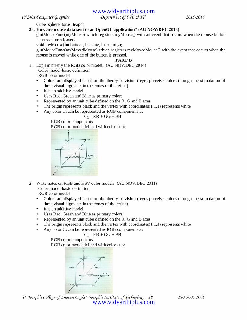
1. Explain briefly the RGB color model. (AU NOV/DEC 2014) Color model-basic definition
RGB color model
• Colors are displayed based on the theory of vision ( eyes perceive colors through the stimulation of
three visual pigments in the cones of the retina) • It is an additive model
• Uses Red, Green and Blue as primary colors
• Represented by an unit cube defined on the R, G and B axes
• The origin represents black and the vertex with coordinates(1,1,1) represents white
• Any color Cλ can be represented as RGB components as
Cλ = RR + GG + BB
RGB color components RGB color model defined with color cube
2. Write notes on RGB and HSV color models. (AU NOV/DEC 2011)
Color model-basic definition RGB color model
• Colors are displayed based on the theory of vision ( eyes perceive colors through the stimulation of
three visual pigments in the cones of the retina)
• It is an additive model
• Uses Red, Green and Blue as primary colors
• Represented by an unit cube defined on the R, G and B axes • The origin represents black and the vertex with coordinates(1,1,1) represents white
• Any color Cλ can be represented as RGB components as
Cλ = RR + GG + BB
RGB color components
RGB color model defined with color cube
www.vidyarthiplus.com
www.vidyarthiplus.com

CS2401-Computer Graphics Department of CSE & IT 2015-2016
St. Joseph’s College of Engineering/St. Joseph’s Institute of Technology 29 ISO 9001:2008
HSV color model
Color parameters-hue (H) saturation (S) and value (V) The HSV hexcone
Cross section of the HSV hexcone
• Color parameters used are
• hue
• saturation
• value • Color is described by adding either black or white to the pure hue
• Adding black decreases V while S remains constant
• Adding white decreases S while V remains constant
• Hue is represented as an angle about vertical axis ranging from 0 degree to 360 degrees
• S varies from 0 to 1
V varies from 0 to 1
3. Compare and contrast between RGB and CMY color models. (AU MAY/JUNE 2012)
RGB color model Color model-basic definition
RGB color model
• Colors are displayed based on the theory of vision ( eyes perceive colors through the stimulation of
three visual pigments in the cones of the retina)
• It is an additive model • Uses Red, Green and Blue as primary colors
• Represented by an unit cube defined on the R, G and B axes
• The origin represents black and the vertex with coordinates(1,1,1) represents white
• Any color Cλ can be represented as RGB components as
Cλ = RR + GG + BB
RGB color components RGB color model defined with color cube
CMY color model Basic colors
The CMY color model defined with subtractive process inside a unit cube
• Based on subtractive process
• Primary colors are cyan , magenta , yellow • Useful for describing color output to hard copy devices
• Color picture is produced by coating a paper with color pigments
www.vidyarthiplus.com
www.vidyarthiplus.com

CS2401-Computer Graphics Department of CSE & IT 2015-2016
St. Joseph’s College of Engineering/St. Joseph’s Institute of Technology 30 ISO 9001:2008
• The printing process generates a color print with a collection of four ink dots ( one each for the primary &
one for black)
RGB to CMY transformation matrix-CMY to RGB transformation matrix C 1 R
M = 1 - G
Y 1 B
4. Briefly explain different color models in detail(AU MAY/JUNE 2013, NOV/DEC 2013 & MAY/JUNE
2014) RGB color model
RGB color model
• Colors are displayed based on the theory of vision ( eyes perceive colors through the stimulation of
three visual pigments in the cones of the retina) • It is an additive model
• Uses Red, Green and Blue as primary colors
• Represented by an unit cube defined on the R, G and B axes
• The origin represents black and the vertex with coordinates(1,1,1) represents white
• Any color Cλ can be represented as RGB components as
Cλ = RR + GG + BB CMY color model
The CMY color model defined with subtractive process inside a unit cube
• Based on subtractive process
• Primary colors are cyan , magenta , yellow
• Useful for describing color output to hard copy devices
• Color picture is produced by coating a paper with color pigments
• The printing process generates a color print with a collection of four ink dots ( one each for the primary & one for black)
RGB to CMY transformation matrix-CMY to RGB transformation matrix
HSV color model
Color parameters-hue (H) saturation (S) and value (V) The HSV hexcone
Cross section of the HSV hexcone
YIQ color model
Basic concept-Parameters used
RGB to YIQ conversion transformation matrix
YIQ to RGB conversion transformation matrix
5. i) Explain in detail the CMY color model. (8)
CMY color model
The CMY color model defined with subtractive process inside a unit cube • Based on subtractive process
• Primary colors are cyan , magenta , yellow
www.vidyarthiplus.com
www.vidyarthiplus.com

CS2401-Computer Graphics Department of CSE & IT 2015-2016
St. Joseph’s College of Engineering/St. Joseph’s Institute of Technology 31 ISO 9001:2008
• Useful for describing color output to hard copy devices
• Color picture is produced by coating a paper with color pigments
• The printing process generates a color print with a collection of four ink dots ( one each for the
primary & one for black) RGB to CMY transformation matrix-CMY to RGB transformation matrix
ii) Mention the salient features of raster animation. (8) (AU MAY/JUNE 2012 IT) & AU NOV/DEC
2014) Raster animation-definition
• This is the most common animation technique
• Frames are copied very fast from off-screen memory to the frame buffer • Copying usually done with bitBLT-type operations
• Copying can be applied to
– complete frames – only parts of the frame which contain some movement
Example with diagram
Procedure
A part of the frame in the frame buffer needs to be erased The static part of the frame is re-projected as a whole, and the animated part is over-projected
6. Discuss the computer animation techniques. (AU NOV/DEC 2012) Computer animation-definition
Raster animations-concept
• This is the most common animation technique • Frames are copied very fast from off-screen memory to the frame buffer
• Copying usually done with bitBLT-type operations
• Copying can be applied to
– complete frames – only parts of the frame which contain some movement
Example with diagram
Procedure A part of the frame in the frame buffer needs to be erased
The static part of the frame is re-projected as a whole, and the animated part is over-projected
Keyframe systems- concept
• Compute first a small number of key frames • Interpolate the remaining frames in-between these key frames (in-betweening)
• Key frames can be computed
– at equal time intervals – according to some other rules
– for example when the direction of the path changes rapidly
7. Explain in detail about morphing.
Morphing is an image processing technique typically used as an animation tool for the metamorphosis
from one image to another. The whole metamorphosis from one image to the other consists of fading out
the source image and fading in the destination image. Thus, the early images in the sequence are much like the source image and the later images are more like the destination image. The middle image of the
sequence is the average of the source image distorted halfway toward the destination image and the
destination image distorted halfway back to the source image. This middle image is rather important for the whole morphing process. If it looks good then probably the entire animated sequence will look good.
For example, when morphing between faces, the middle "face" often looks strikingly "life-like" but is
neither the first nor the second person in the image.
8. Discuss the basic OPENGL operations. (AU NOV/DEC 2011) & (AU NOV/DEC 2014)
www.vidyarthiplus.com
www.vidyarthiplus.com

CS2401-Computer Graphics Department of CSE & IT 2015-2016
St. Joseph’s College of Engineering/St. Joseph’s Institute of Technology 32 ISO 9001:2008
OpenGL provides tools for drawing all output primitives
The o/p primitives are defined by one or more vertices To draw an object in OpenGL pass a list of vertices
The vertices list must occur between two OpenGL function calls glBegin() and glEnd()
Ex.
To draw three points on(100,50),(100,130) &(150,130) the command sequence is glBegin(GL_POINTS);
glVertex2i(100,50);
glVertex2i(100,130); glVertex2i(150,130);
glEnd();
dot constellation is some pattern of dots or points Ex. Sierpinski gasket
Procedure
• Choose 3 fixed points T0,T1,T2 to form some triangle
• Choose the initial point P0 to be drawn by selecting one of the point T0,T1 & T2 at random
o Now iterate the following steps until pattern is satisfyingly filled in • Choose one of the 3 points T0,T1 & T2 at random call it T
• Construct the next point Pk as the midpoint between T and previously found point Pk-1
• Draw Pk using drawDot()
9. Discuss the methods to draw 3D objects and 3D scenes (AU MAY/JUNE 2014 & NOV/DEC 2014) Explain with an example code. (AU MAY/JUNE 2012 IT & MAY/JUNE 2012 & MAY/JUNE 2013))
The graphics package implemented by OpenGL does its major work through matrix transformations
OpenGL pipeline The vertices of the objects are multiplied by the various matrices like the modelview matrix, projection matrix and viewport matrix and then they are clipped if necessary and after clipping the
survived vertices are mapped onto the viewport
SDL – Scene Description Language Tool to describe a scene
Defines a scene class
Scene class supports the reading of the SDL file & the drawing of the objects described in the file
read( ) method of the secen class is used to read the scene file glBegin(GL_LINE_LOOP);
glVertex2i(20,10);
glVertex2i(50,10); glVertex2i(20,80);
glVertex2i(50,80);
glEnd(); glFlush();
10. Discuss the methods used in OPENGL for handling a window and also write a simple program to display
a window on the screen. (AU NOV/DEC 2013). void main(int argc, char** argv)
{
glutInit(&argc, argv); glutInitDisplayMode(GLUT_SINGLE |GLUT_RGB):
glutInitWindowSize(640,480);
glutInitWindowPosition(100,150); glutCreateWindow(―my first attempt);
// register call back functions
glutDisplayFunc(myDisplay);
glutReshapeFunc(myReshape);
www.vidyarthiplus.com
www.vidyarthiplus.com

CS2401-Computer Graphics Department of CSE & IT 2015-2016
St. Joseph’s College of Engineering/St. Joseph’s Institute of Technology 33 ISO 9001:2008
glutMouseFunc(myMouse);
glutKeyboardFunc(myKeyboard); myInit();
glutMainLoop();
}
UNIT IV
RENDERING
1. What is a shading model?
Define shading. (AU MAY/JUNE 2012)
What do you mean by shading of objects? (AU NOV/DEC 2011)
Shading attempts to model how light that emanates from light sources would interact with objects in a scene. Usually it does not try to simulate all of the physical principles having to do with the scattering and
reflection of light.
2. Differentiate flat and smooth shading. (AU MAY/JUNE 2012 IT)
Flat Shading Smooth Shading
A calculation of how much light is scattered from
each face is computed at a single point, so all
points on a face are rendered with the same gray
level.
Smooth shading attempts to de-emphasize edges
between faces by computing colors at more points
on each face.
Edges between faces appear more pronounced than
they would be on an actual physical objects
The variation in gray levels is much smoother and
the edges of the polygon disappear, giving the
impression of an even surface.
3. What is meant by flat shading? (AU MAY/JUNE 2014 & NOV/DEC 2014) It is a shading technique in which the entire face is filled with a single color that was computed at only
one vertex . It is employed when the face is flat and the light source is far distant from the face.
4. Define flat shading and Gouraud shading. A calculation of how much light is scattered from each face is computed at a single point, so all points on
a face are rendered with the same gray level is flat shading. In Gouraud shading,different points of a face
are drawn with different gray levels found through an interpolation scheme.
5. Which shading model is faster and easier to calculate? Why? (AU NOV/DEC 2103)
Flat shading is faster and easier to calculate because the entire face is drawn with the same color. In this
method although a color is passed down the pipeline as part of each vertex of the face, the painting
algorithm uses only one color value.
6. What is Achromatic light?
It has brightness, but no color. Achromatic light is only a shade of gray; hence it is described by a single
value: its intensity.
7. What are the two types of light sources that illuminate the objects in a scene?
The two light sources are point light source and ambient light.
8. What are the different ways by which the incident light interacts with the surface? The three different ways are: some is absorbed by the surface and is converted to heat, some is reflected
from the surface and some is transmitted into the interior of the object, as in the case of a piece of glass.
9. Define blackbody.
If the entire incident light is absorbed, the object appears black and is known as blackbody.
10. What are the types of reflection of incident light? (AU NOV/DEC 2013)
The two types are diffuse scattering and specular reflections.
www.vidyarthiplus.com
www.vidyarthiplus.com

CS2401-Computer Graphics Department of CSE & IT 2015-2016
St. Joseph’s College of Engineering/St. Joseph’s Institute of Technology 34 ISO 9001:2008
11. What are the three vectors to be found, to compute the diffuse and specular components of light?
The three vectors are: the normal vector m to the surface at P, the vector v from P to the viewer‘s eye, the vector s from P to the light source.
12. What is specular reflection?
Real objects do not scatter light uniformly in all directions, so a specular component is added to the
shading model. Specular reflection causes highlights, which can add significantly to the realism of a picture when objects are shiny.
13. What is tiler?
A polygon filling routine is sometimes called a tiler, because it moves over the polygon pixel by pixel, coloring each pixel appropriately. The pixels are visited in regular order, usually scan line by scan line
from bottom to top and across each scan line left to right.
14. What are the principal types of smooth shading? The two principal types of smooth shading are Gouraud shading and Phong shading.
15. Define texture pattern. (AU NOV/DEC 2011, NOV/DEC 2012, MAY/JUNE 2012, MAY/JUNE 2014
& NOV/DEC 2014)
Texture can add realism to objects. These textures can make various surfaces appear to be made of some material such as wood, marble or copper. Images can be ―wrapped around‖ an object like a label.
16. How do you add texture to faces? (AU MAY/JUNE 2014)
Pasting the texture onto a flat surface
Rendering the texture
Wrapping texture on curved surfaces
Reflection mapping
17. What are the most common sources of textures? What are bitmap textures and procedural
textures?
The most common sources of textures are bitmap textures and procedural textures. Textures are often
formed by bitmap representation of images. Such representation consists of an array of color values, often called as texels. This is called bitmap texture. Procedural texturesdefine texture by a mathematical
function or procedure.
18. Define texture space.
Texture space is traditionally marked off by parameters named s and t. The function of texture(s,t) produces a color or intensity value for each value of s and t between 0 and 1.
19. What is reflection mapping? Mention its types.
The class of techniques known as reflection mapping can significantly improve the realism of pictures, particularly animation. The basic idea is to see reflection in an object that suggest the ―world‖
surrounding that object.The types are: chrome mapping and environment mapping.
20. Define chrome mapping. A rough and usually blurry image that suggests that surrounding environment is reflected in the object, as
a surface coated with chrome.
21. Define environment mapping.
A recognizable image of the surrounding environment is seen reflected in the object. We get valuable visual cues from such reflections, particularly when the object moves about.
22. What is Bump mapping?
It is a technique to give a surface a wrinkled or dimpled appearance without struggling to model the dimple itself.
23. How to create a glowing object?
The visible intensity I is set equal to the texture value at each spot: I=texture(s,t). The object then appears
to emit light or glow. Lower texture values emit less light and higher texture values emit more light.
24. What is Phong shading?
Phong shading finds a normal vector at each point on the face of the object and then applies the shading
model there to find the color. Compute the normal vector at each pixel by interpolating the normal vectors at the vertices of the polygon.
www.vidyarthiplus.com
www.vidyarthiplus.com

CS2401-Computer Graphics Department of CSE & IT 2015-2016
St. Joseph’s College of Engineering/St. Joseph’s Institute of Technology 35 ISO 9001:2008
25. What is a shadow? (AU NOV/DEC 2012)
Shadow adds more realism to objects. The way one object casts a shadow on another object gives important visual cues as to how the two objects are positioned with respect to each other. Shadows are the
darker portions in a scene which is formed by obstruction of light by an object.
26. How are shadow areas displayed? (AU MAY/JUNE 2012 IT)
First compute the shape of the shadow being cast. It is determined by the projections of each of the faces of the object onto the plane of the floor, using light source as center of projection. After drawing the plane
by the use of ambient, diffuse and specular light contributions, draw the projections using only ambient
light. This will draw the shadow in the right shape and color. Finally draw the object.
27. Define rendering. (AU MAY/JUNE 2013)
It is the added realism in displays by setting the surface intensity of objects according to the lighting
conditions in the scene and according to the assigned surface characteristics.
28. What is dithering? (AU MAY/JUNE 2013)
It refers to techniques for approximating halftones without reducing resolution as pixel grid patterns do.
29. What are the stages of rendering in creating shadows?
The stages are: loading shadow buffer and rendering the scene.
PART B
1. Explain about shading models. (AU MAY/JUNE 2012)
Shading Model
explains the scattering / reflecting of light from a surface Flat Shading
The entire face is filled with a color that was computed at only one vertex
OpenGL command
glShadeModel(GL_FLAT); Smooth Shading
It deemphasizes the edges between faces by computing colors at more points on each face
Types
Gouraud shading - Computes a different value of c (color) for each pixel
- For each scan line find
The color at leftmost pixel (colorleft ) by linear interpolation of colors at the top and bottom of the left edge of the polygon
The color at the rightmost pixel (colorright ) by linear interpolation of colors at the top and bottom
of the right edge of the polygon
- The color at pixel x is obtained by
c(x) = lerp( colorleft , colorright , x-xleft /xright - x left ) To increase the efficiency of the fill , this color is computed incrementally at each pixel
c(x+1) = c(x) + colorright - colorleft / xright - x left Phong shading
OpenGL performs only Gouraud shading
Find the normal vector at each point on the face of the object and then apply shading model to find the color
Normal vector at each point / pixel is computed by interpolating the normal vectors at the vertices
of the polygon
For each scan line find the vectors mleft and mright by linear interpolation Interpolate mleft and mrightto find the normal vector at each pixel position
Normalize the interpolated vector to be used for shading calculation to form the color at the pixel
position
2. Give an account about specular reflection.
Specular reflection
www.vidyarthiplus.com
www.vidyarthiplus.com

CS2401-Computer Graphics Department of CSE & IT 2015-2016
St. Joseph’s College of Engineering/St. Joseph’s Institute of Technology 36 ISO 9001:2008
Incident light does not penetrate the object & is reflected directly from the outer surface of the
object and gives rise to highlights
Mirror like reflection and is highly directional
Models of specular reflection
Simple model
reflected light has same color as incident light
Complex model
color of light varies over the highlights
Total light relected from a surface in a direction
Total light reflected = Diffuse component + Specular component
Geometric Ingredients for finding Reflected light
• Normal vector, m to the surface
• Vector v from the surface P to the viewer‘s eye
• Vector s from the surface P to the light source
Specular Reflection causes highlights
Phong model
discusses the behavior of specular light
used when the object is made up of shiny plastic / glass
The amount of light reflected is greatest in the direction of a perfect mirror
reflection , r, where the angle of incidence equals the angle of reflection
Isp = (Isρs ) ( r.v/|r||v|)f
if r.v is ‗-‘ve Isp = 0 , f choosen experimentally from 1 to 200
Alternative approach
find halfway between ‗s‘ and ‗v‘ ( i.e) h
Isp = (Isρs ) max (0, h.m/|h||m|)f
Role of ambient light Ambient light – background glow that exists in the environment
Ambient light source spreads light uniformly in all directions
Combining Light Contributions
I= Iaρa + Idρd * lambert + Ispρs * phongf
Adding color
Ir= Iarρar + Idrρdr * lambert + Isprρsr * phongf
Ig = Iagρag + Idgρdg * lambert + Ispgρsg * phongf
Ib= Iabρab + Idbρdb * lambert + Ispbρsb * phongf
3. Differentiate flat and smooth shading models. (AU NOV/DEC 2012)
Compare Flat Shading and Smooth shading with respect to their characteristics and types. (AU
NOV/DEC 2013)
Explain the steps involved in Smooth and Flat shading. (AU NOV/DEC 2014)
Shading Model
explains the scattering / reflecting of light from a surface Flat Shading
The entire face is filled with a color that was computed at only one vertex
OpenGL command glShadeModel(GL_FLAT);
Smooth Shading
It deemphasizes the edges between faces by computing colors at more points on each face
www.vidyarthiplus.com
www.vidyarthiplus.com

CS2401-Computer Graphics Department of CSE & IT 2015-2016
St. Joseph’s College of Engineering/St. Joseph’s Institute of Technology 37 ISO 9001:2008
Types
Gouraud shading Computes a different value of c (color) for each pixel
For each scan line find
The color at leftmost pixel (colorleft ) by linear interpolation of colors at the top and bottom of the left
edge of the polygon The color at the rightmost pixel (colorright ) by linear interpolation of colors at the top and bottom of the
right edge of the polygon
The color at pixel x is obtained by
c(x) = lerp( colorleft , colorright , x-xleft /xright - x left ) To increase the efficiency of the fill , this color is computed incrementally at each pixel
c(x+1) = c(x) + colorright - colorleft / xright - x left Phong shading
OpenGL performs only Gouraud shading
Find the normal vector at each point on the face of the object and then apply shading model to
find the color Normal vector at each point / pixel is computed by interpolating the normal vectors at the vertices
of the polygon
For each scan line find the vectors mleft and mright by linear interpolation Interpolate mleft and mrightto find the normal vector at each pixel position
Normalize the interpolated vector to be used for shading calculation to form the color at the pixel
position
4. Give an account of creating shaded objects. (AU MAY/JUNE 2012 IT)
Discuss about creation, rendering textures and drawing shadows for shaded objects. (AU MAY/JUNE
2014) Shadow buffer method
Shadow buffer – auxiliary second depth buffer contains depth picture of a scene
from the point of view of light source - Employs a shadow buffer for each light source
Condition: Any point that is hidden from the light source must be in a shadow
Rendering:
2 stages 1. Loading shadow buffer
2. Rendering the scene
Loading Shadow Buffer Shadow buffer is initialized with 1.0 in each element, the largest pseudo depth
Through a camera positioned at the light source each of the faces in the scene is rasterized but only the
pseudo depth of the point on the face is tested Each element in the shadow buffer now keep track of the smallest pseudo depth seen so far
whenever the objects move relative to light source shadow buffer has to be recalculated
Rendering the scene Each face in the scene is rendered by the eye camera. If the eye camera sees the point P through pixel
p[c][r],rendering p[c][r] finds
(i) pseudo depth ,D from the source to P (ii) index location [i][j] in shadow buffer
(ii) value d[i][j] stored in shadow buffer
If d[i][j] is < than D, point P is in shadow set p[c][r] using ambient light
If d[i][j] is > than D, point P is not in shadow
set p[c][r] using ambient , diffuse & specular light
www.vidyarthiplus.com
www.vidyarthiplus.com

CS2401-Computer Graphics Department of CSE & IT 2015-2016
St. Joseph’s College of Engineering/St. Joseph’s Institute of Technology 38 ISO 9001:2008
Rendering the texture in a face
Approach similar to Gouraud Shading
- Proceed across the face pixel by pixel
- For each pixel
determine the corresponding texture coordinates (s,t) Access the texture
Set the pixel to the proper texture color
When moving across the scan line compute (sleft,tleft ) and (sright , tright) for each scan line in a rapid incremental fashion and interpolate between these values
5. Explain Gouraud shading technique and write the deficiencies in that method and how it is rectified using
Phong shading technique.(AU MAY/JUNE 2013)
Gouraud shading
- Computes a different value of c (color) for each pixel - For each scan line find
The color at leftmost pixel (colorleft ) by linear interpolation of colors at the top and bottom of
the left edge of the polygon The color at the rightmost pixel (colorright ) by linear interpolation of colors at the top and bottom
of the right edge of the polygon
- The color at pixel x is obtained by
c(x) = lerp( colorleft , colorright , x-xleft /xright - x left ) To increase the efficiency of the fill , this color is computed incrementally at each pixel
c(x+1) = c(x) + colorright - colorleft / xright - x left Phong shading
OpenGL performs only Gouraud shading
Find the normal vector at each point on the face of the object and then apply shading model to
find the color Normal vector at each point / pixel is computed by interpolating the normal vectors at the vertices
of the polygon
For each scan line find the vectors mleft and mright by linear interpolation
Interpolate mleft and mrightto find the normal vector at each pixel position Normalize the interpolated vector to be used for shading calculation to form the color at the pixel
position
6. Explain about adding texture to faces of real objects (AU MAY/JUNE 2012 IT & NOV/DEC 2013)
&(AU NOV/DEC 2014)
Texture function texture(s,t)
Produces a color / intensity value for each value of ‗s‘ and ‗t‘ between ‗0‘ and ‗1‘
Sources of texture
Bitmaps Computed functions / procedural textures
Bitmap Textures
- Textures are formed from bitmap representations of images - This representation consists of an array of color values called texels (txtr[c][r])
Bitmap Texture
color3 texture(float s, float r) { returntxtr[(int)(s*c)][(int)(t*r)]; }
Procedural Texture
- Defined by mathematical function / procedure
float fakeSphere(float s , float t)
www.vidyarthiplus.com
www.vidyarthiplus.com

CS2401-Computer Graphics Department of CSE & IT 2015-2016
St. Joseph’s College of Engineering/St. Joseph’s Institute of Technology 39 ISO 9001:2008
{ float r = sqrt((s - 0.5) * (s - 0.5) + (t - 0.5) * (t - 0.5));
if (r < 0.3 ) return 1 - r/0.3; // sphere intensity
else
return 0.2; //dark background
}
Pasting Texture onto a Flat Face
glTexCoord2f( ) function used to associate a point in texture space , P = (si , ti ) with each vertex Vi of
the face
glTexCoord2f( ) function usually precedes the call to glVertex3f( ) function
Rendering the texture in a face
Approach
similar to Gouraud Shading
- Proceed across the face pixel by pixel - For each pixel
determine the corresponding texture coordinates (s,t)
Access the texture Set the pixel to the proper texture color
When moving across the scan line compute (sleft,tleft ) and (sright , tright) for each scan line in a rapid
incremental fashion and interpolate between these values
Wrapping Texture on Curved Surfaces
1. Wrapping a label around a can
-Model the can/cylinder as a polygonal mesh ( walls are rectangular strips )
-Extend the label from Θa toΘb in azimuth (angular distance )and from Z a to Z b along Z-axis
-For each vertex Vi of each face find the suitable texture coefficient (si ,vi ) and map it
onto the face s = Θ - Θa / Θb -Θa , t = Z -Z a / Z b -Z a
If there are N faces around the cylinder , the ith
face has the left edge at azimuth Θi = 2Πi /
N The upper left vertex has texture coordinates (si , ti )
(si , ti ) = ((2Πi / N -Θa ) / (Θb -Θa ), 1)
2. Shrink wrapping a label onto a surface of revolution Shrink wrapping
wrap the texture about an imaginary rubber cylinder & then let the cylinder to collapse ,
the texture points are now radically slide until it hits the surface of the vase (container) - 3 approaches
(i)Associate the texture point Pi with the object point Vi that lies along the normal from Pi ( use texture
point‘s normal vector)
(ii)Associate the texture point on the imaginary cylinder with vertices on the object by drawing a line from the object‘s centriod C , through the vertex Vi until it intersects with the cylinder (use centriod)
(iii)Associate the texture point with the object point by using the normal vector to the object‘s surface ( use
object‘s normal vector)
3. Mapping texture onto a sphere
- use the linear mapping function
If vertex Vi lies at (Θi,Φ) associate it with the texture coordinates
(si , ti) = ((Θ -Θi)/ (Θb -Θa ) , (Φ - Φ i)/ (Φ b -Φ a ))
4. Mapping texture to sphere like objects
- 3 ways
(i) objectcentriod
www.vidyarthiplus.com
www.vidyarthiplus.com

CS2401-Computer Graphics Department of CSE & IT 2015-2016
St. Joseph’s College of Engineering/St. Joseph’s Institute of Technology 40 ISO 9001:2008
(ii) object normal
(iii) sphere normal
Reflection Mapping
Types
Chrome mapping Environment mapping
7. Explain about adding shadows to objects. (AU MAY/JUNE 2012 IT, NOV/DEC 2013, MAY/JUNE 2014 & NOV/DEC 2014)
Methods for computing Shadows
1. Painting the shadow (as texture) 2. Shadow buffer method (removal of the hidden surfaces)
Shadows as texture
Draw the plane by using ambient, diffuse & specular light contributions and then draw
the six projections on the plane using only ambient light Shadow buffer method
Shadow buffer – auxiliary second depth buffer contains depth picture of a scene from the
point of view of light source - Employs a shadow buffer for each light source
Condition: Any point that is hidden from the light source must be in a shadow
Rendering: 2 stages
1. Loading shadow buffer
2. Rendering the scene
Loading Shadow Buffer Shadow buffer is initialized with 1.0 in each element, the largest pseudo depth
Through a camera positioned at the light source each of the faces in the scene is rasterized but only the
pseudo depth of the point on the face is tested Each element in the shadow buffer now keep track of the smallest pseudo depth seen so far
- whenever the objects move relative to light source shadow buffer has to be recalculated
Rendering the scene
Each face in the scene is rendered by the eye camera. If the eye camera sees the point P through pixel p[c][r],rendering p[c][r] finds
(i) pseudo depth ,D from the source to P
(ii) index location [i][j] in shadow buffer
(ii) value d[i][j] stored in shadow buffer
If d[i][j] is < than D, point P is in shadow
set p[c][r] using ambient light If d[i][j] is > than D, point P is not in shadow
set p[c][r] using ambient , diffuse & specular light
8. Give an account on drawing shadows. (AU MAY/JUNE 2012 IT & NOV/DEC 2012)
Shadow buffer method
Shadow buffer – auxiliary second depth buffer contains depth picture of a scene from the point of view of light source
- Employs a shadow buffer for each light source
Condition: Any point that is hidden from the light source must be in a shadow
Rendering: 2 stages
3. Loading shadow buffer
4. Rendering the scene Loading Shadow Buffer
www.vidyarthiplus.com
www.vidyarthiplus.com

CS2401-Computer Graphics Department of CSE & IT 2015-2016
St. Joseph’s College of Engineering/St. Joseph’s Institute of Technology 41 ISO 9001:2008
Shadow buffer is initialized with 1.0 in each element, the largest pseudo depth
Through a camera positioned at the light source each of the faces in the scene is rasterized but only the pseudo depth of the point on the face is tested
Each element in the shadow buffer now keep track of the smallest pseudo depth seen so far
whenever the objects move relative to light source shadow buffer has to be recalculated
Rendering the scene
Each face in the scene is rendered by the eye camera. If the eye camera sees the point P through pixel
p[c][r],rendering p[c][r] finds (i) pseudo depth ,D from the source to P
(ii) index location [i][j] in shadow buffer
(ii) value d[i][j] stored in shadow buffer If d[i][j] is < than D, point P is in shadow
set p[c][r] using ambient light
If d[i][j] is > than D, point P is not in shadow
set p[c][r] using ambient , diffuse & specular light
9. Write down and explain the details to build a camera in a program. (AU NOV/DEC 2011, MAY/JUNE 2014 & NOV/DEC 2014)
To have fine control over camera movements we create and manipulate our own camera in a
program Steps:
1. Create Camera class
2. Create an object cam
Functions: - cam.set(eye,look,up); // initialize the camera
- cam.slide(-1,0,-2); // slide camera forward & to left
- cam.roll(30); // roll it through 30 degrees - cam.yaw(20); // yaw it through 20 degrees
Class Camera
{ private:
Points3 eye; Vector3 u,v,n;
double viewAngle,aspect,nearDist,farDist;
void setModelViewMatrix(); public:
Camera();
void set(Point3 eye , Point3 look , Vector3 up); void roll(float angle);
void pitch(float angle);
void yaw(float angle);
void slide(float deluU, float delV , float delN ); voidsetShape(float vAng , float asp , float nearD , float farD);
};
Utility routines - set() acts like gluLookAt() & places the info. of eye, look, up in camera‘s field and communicates
with OpenGL
- setModelViewMatrix() communicates the MVMatrix to OpenGL void Camera::setModelViewMatrix(void)
{ float m[16];
Vector3 eVec(eye.x , eye.y , eye.z)
m[0] = u.x ; m[4] = u.y ; m[8] = u.z ; m[12] = -eVec.dot(u);
www.vidyarthiplus.com
www.vidyarthiplus.com

CS2401-Computer Graphics Department of CSE & IT 2015-2016
St. Joseph’s College of Engineering/St. Joseph’s Institute of Technology 42 ISO 9001:2008
m[1] = v.x ; m[5] = v.y ; m[9] = v.z ; m[13] = -eVec.dot(v);
m[2] = n.x ; m[6] = n.y ; m[10] = n.z ; m[14] = -eVec.dot(n); m[3] = 0 ; m[7] = 0 ; m[11] = 0 ; m[15] =1.0;
glMatrixMode(GL_MODELVIEW);
glLoadMatrixf(m);
} void Camera::set(Point3 Eye , Point3 look , Vector3 up)
{ eye.set(Eye);
n.set(eye.x – look.x , eye.y – look.y , eye.z – look.z); u.set(up.cross(n)); // make u = up x n
n.normalize();
u.normalize(); v.set(n.cross(u)); // make v = n x u
setModelViewMatrix(); // tell OpenGL
}
Sliding the camera void Camera::slide(float delU , float delV , float delN)
{ eye.x += delU * u.x + delV * v.x + delN * n.x ;
eye.y += delU * u.y + delV * v.y + delN * n.y ; eye.z += delU * u.z + delV * v.z + delN * n.z ;
setModelViewMatrix();
} Rotating the camera
Void Camera::roll( float angle)
{ float cs = Cos(3.14159265 / 180 * angle);
float sn = Sin(3.14159265 / 180 * angle); Vector3 t = u;
u.set(cs * t.x – sn * v.x , cs * t.y – sn * v.y , cs * t.z – sn * v.z );
v.set(sn * t.x + cs * v.x , sn * t.y + cs * v.y , sn * t.z + cs * v.z ); setModelViewMatrix();
10. Explain in detail how texture can be rendered.
Total light relected from a surface in a direction Total light reflected = Diffuse component + Specular component
Geometric Ingredients for finding Reflected light
1. Normal vector, m to the surface 2. Vector v from the surface P to the viewer‘s eye
3. Vector s from the surface P to the light source
Specular Reflection - causes highlights
Phong model
discusses the behavior of specular light
used when the object is made up of shiny plastic / glass The amount of light reflected is greatest in the direction of a perfect mirror reflection , r,
where the angle of incidence equals the angle of reflection
Isp = (Isρs ) ( r.v/|r||v|)f
if r.v is ‗-‘ve Isp = 0 , f choosen experimentally from 1 to 200
Alternative approach
find halfway between ‗s‘ and ‗v‘ ( i.e) h
Isp = (Isρs ) max (0, h.m/|h||m|)f
Role of ambient light Ambient light – background glow that exists in the environment
Ambient light source spreads light uniformly in all directions
www.vidyarthiplus.com
www.vidyarthiplus.com

CS2401-Computer Graphics Department of CSE & IT 2015-2016
St. Joseph’s College of Engineering/St. Joseph’s Institute of Technology 43 ISO 9001:2008
Combining Light Contributions
I= Iaρa + Idρd * lambert + Ispρs * phongf
Adding color
Ir= Iarρar + Idrρdr * lambert + Isprρsr * phongf
Ig = Iagρag + Idgρdg * lambert + Ispgρsg * phongf
Ib= Iabρab + Idbρdb * lambert + Ispbρsb * phongf
Flat Shading The entire face is filled with a color that was computed at only one vertex
OpenGL command
glShadeModel(GL_FLAT);
Smooth Shading It deemphasizes the edges between faces by computing colors at more points on each face
Types
1. Gouraud shading - Computes a different value of c (color) for each pixel
- For each scan line find
The color at leftmost pixel (colorleft ) by linear interpolation of colors at the top and bottom of the left edge of the polygon
The color at the rightmost pixel (colorright ) by linear interpolation of colors at the top and bottom
of the right edge of the polygon
- The color at pixel x is obtained by
c(x) = lerp( colorleft , colorright , x-xleft /xright - x left ) To increase the efficiency of the fill , this color is computed incrementally at each pixel
c(x+1) = c(x) + colorright - colorleft / xright - x left 2. Phong shading
OpenGL performs only Gouraud shading
Find the normal vector at each point on the face of the object and then apply shading model to find the color
Normal vector at each point / pixel is computed by interpolating the normal vectors at the vertices
of the polygon
For each scan line find the vectors mleft and mright by linear interpolation Interpolate mleft and mrightto find the normal vector at each pixel position
Normalize the interpolated vector to be used for shading calculation to form the color at the pixel
position
UNIT V
FRACTALS
1. What are fractals? (AU NOV/DEC 2011, MAY/JUNE 2012 IT & MAY/JUNE 2012) Fractals are those which have the property of a shape that has the same degree of roughness no matter
how much it is magnified. A fractal appears ―the same‖ at every scale. No matter how much one enlarges
a picture of the curve, it has the same level of detail.
2. Define self-similar.
Most of the curves and pictures have a particularly important property: they are self-similar. This means
that they appear ―the same‖ at every scale. No matter how much one enlarges a picture of the curve, it has the same level of detail
3. Mention the types of self-similar.
The types are: exactly self-similar and statistically self-similar.
4. What is Koch curve? Very complex curves can be fashioned recursively by repeatedly ―refining‖ a simple curve. The simplest
is the Koch curve. This curve stirred great interest in the mathematical world because it produces a
infinitely long line within a region of finite area.
www.vidyarthiplus.com
www.vidyarthiplus.com

CS2401-Computer Graphics Department of CSE & IT 2015-2016
St. Joseph’s College of Engineering/St. Joseph’s Institute of Technology 44 ISO 9001:2008
5. What are Peano curves?
List down the properties of Peano curves. (AU NOV/DEC 2012 & MAY/JUNE 2014) A fractal curve can in fact ―fill the plane‖ and therefore have a dimension of 2. Such curves are called
Peano curves.
6. What is a L-System?
A large number of interesting curves can be generated by refining line segments. A particularly simple approach to generating these curves uses so called L-Systems to draw complex curves based on simple set
of rules.
7. Mention the dragon rules. The dragon rules are ‗F‘ ‗F‘,
‗X‘ ―X+YF+‖,
‗Y‘ ―-FX-Y‖, atom=‖FX‖
8. What is space-filling?
Such curves have a fractal dimension of 2 and they completely fill a region of space.
9. What are the two famous Peano curves? The two famous Peano curves are: Hilbert and Sierpinski curves.
10. Define fractal trees.
Fractal trees provide an interesting family of shapes that resemble actual trees. Such shrubbery can be used to ornament various drawings.
11. What is periodic tiling and dihedral tiling?
In periodic tiling, the notion is to take many copies of some shape such as polygon and to fit them together as a jigsaw puzzle so that they cover the entire plane with no gaps. In dihedral tiling, they permit
the use of two prototiles and therefore offer many more possibilities.
12. How can a black and white image be described?
A black and white image I can be described simply as the set of its black points: I =set of all black points={(x,y) such that (x,y) is coloured black}.
13. What is the “Chaos Game”?
It ia also known as the random iteration algorithm which offers a simple nonrecursive way to produce a picture of the attractor of an IFS.
14. What is fractal image compression?
The original image is processed to create the list of affine maps, resulting in a greatly compressed
representation of the image.
15. What is Mandelbrot set?
A very famous fractal shape is obtained from the Mandelbrot set, which is a set of complex values z that
do not diverge under the squaring transformation: z0 = z, zk = z2k-1 + z0, k = 1, 2, 3, . . .It is the black
inner portion, which appears to consist of a cardioid along with a number of wart like circles glued to it.
Its border is complicated and this complexity can be explored by zooming in on a portion of the border.
16. Differentiate Mandelbrot sets and Julia sets. (AU NOV/DEC 2011)
Mandelbrot sets Julia sets
A very famous fractal shape is obtained from the
Mandelbrot set, which is a set of complex values z
that do not diverge under the squaring transformation: z0 = z, zk = z
2k-1 + z0, k = 1, 2,
3, . . .
For some functions, the boundary between those
points that move towards infinity and those that
tend toward a finite limit is a fractal. The boundary of the fractal object is called the Julia set.
It is the black inner portion, which appears to
consist of a cardioid along with a number of wart like circles glued to it. Its border is complicated and
this complexity can be explored by zooming in on a
portion of the border.
Julia sets are extremely complicated sets of points
in the complex plane. There is a different Julia set Jc for each value of c.
www.vidyarthiplus.com
www.vidyarthiplus.com

CS2401-Computer Graphics Department of CSE & IT 2015-2016
St. Joseph’s College of Engineering/St. Joseph’s Institute of Technology 45 ISO 9001:2008
17. What is Julia sets? (AU MAY/JUNE 2012 & NOV/DEC 2014)
For some functions, the boundary between those points that move towards infinity and those that tend toward a finite limit is a fractal. The boundary of the fractal object is called the Julia set. Julia sets are
extremely complicated sets of points in the complex plane. There is a different Julia set Jc for each value
of c.
18. Define ray tracing. (AU NOV/DEC 2014) In computer graphics, ray tracing is a technique for generating an image by tracing the path
of light through pixels in an image plane and simulating the effects of its encounters with virtual objects.
19. What are the steps in ray tracing process? How to incorporate texture into a ray tracer?
The steps are: build the rc-th ray, fins the intersections with the object, identify intersections that lie close to and in front of the eye, compute the hit point, find the color of the light and place the color in the rc-th
pixel.Two principal kinds of texture are used: with image texture a 2D image is pasted onto each surface
of the object, with solid texture the object is considered to be carved out of a block of some material.
20. List down the ray tracing methods. (AU MAY/JUNE 2012 IT)
The various ray tracing methods are:
Basic ray-tracing algorithm
Ray-surface intersection calculations
Reducing object-intersection calculations
Space-subdivision methods
Antialiased ray tracing
Distributed ray tracing
21. Where does the ray r(t) = (4,1,3) + (-3,-5,-3)t hit the generic plane? (AU NOV/DEC 2013) The generic plane is the xy plane or z = 0
Its implicit form is F(x,y,z) = z
The hit point is found to be (1,-4,0)
22. What is wood grain texture? As the distance of points from some axis varies, the function jumps back and forth between two values.
This effect can be simulated with the modulo function rings(r)=((int)r)%2 where rings about the z-axis,
the radius r=x2+y
2.
23. Define refraction of light.
When a ray of light strikes a transparent object, a portion of the ray penetrates the object. The ray change direction fromdir to t if the speed of light is different in medium 1 than in medium 2.
24. State Snell’s law.
If the angle of incidence of the ray is 1, Snell‘s law states that the angle of refraction 2 will be
sin(2)/c2=sin(1)/c1
25. What is total internal reflection?
When the smaller angle gets larger enough, it forces the larger angle to 90o. A larger value is impossible,
so no light is transmitted into the second medium. This is called total internal reflection.
26. What are CSG objects?
Objects such as lenses and hollow fishbowls, as well as objects with holes are easily formed by combining the generic shapes treated thus far. They are called compound, Boolean or CSG objects.
27. Write down some of the Boolean operations on objects. (AU NOV/DEC 2012)
Some Boolean operators used on objects are: union, intersection and difference.
28. How objects are modeled using constructive solid geometry technique? (AU NOV/DEC 2013) According to CSG arbitrarily complex shapes are defined by set operation ( Boolean operation) on similar
shapes. Lenses, hallow fish bowls easily formed by combining generic shapes. These objects are called
compound, Boolean or CSG objects. Boolean operation include union, intersection and difference
29. What is the motivation of using projection extends?
There is a strong motivation for using projection extends for CSG objects, due to the cost of ray tracing
them. A projection extend can be built for each node of a CSG object in much the same way as box extends are built.
www.vidyarthiplus.com
www.vidyarthiplus.com

CS2401-Computer Graphics Department of CSE & IT 2015-2016
St. Joseph’s College of Engineering/St. Joseph’s Institute of Technology 46 ISO 9001:2008
30. Mention the characteristics of fractals.
Infinite detail at every point
Self similarity between object parts
31. Define exact self similarity If a region of a curve is enlarged the enlargement looks exactly like the original
32. Define statistical self similarity
If a region is enlarged the enlargement on an average looks like the original
33. How complex curves are fashioned? By successive refinement of simple curve very complex curves can be fashioned
34. How will you generate the Koch curve.
The zeroth
generation shape K0 is a horizontal line of unit length.The curve K1 is generated by dividing K0 into three equal parts and replacing the middle section with a triangular bump.The bump should have
sides of length 1/3 so the length of the line is now 4/3.The second order curve K2 is generated by building
a bump on each of the 4 line segments of K1
35. Mention the curves generated based on string production.
Curves generated based on string production are
Koch curve
Quadratic Koch Island
Hilbert curve
Dragon curve
Gospher hexagonal curve
Sierpinski gasket
Sierpinski arrowhead
36. Mention the Key Ingredients for drawing the curves.
Atom
F-string
X-string
Y-string
Angles in degrees
PART B
1. Briefly explain different types of fractals with neat diagram and also explain how to construct fractals
and the uses of fractals in computer graphics.(AU MAY/JUNE 2013)
Characteristics of a fractal object 1. Infinite detail at every point
2. Self similarity between object parts
Types of self similarity Exact self similarity
Statistical self similarity
Exact self similarity
if a region of a curve is enlarged the enlargement looks exactly like the original Statistical self similarity
if a region is enlarged the enlargement on an average looks like the original
Successive refinement of curves by repeatedly refining a simple curve very complex curves can be fashioned
Ex. Koch curve
Koch curve produces an infinitely long line within a region of finite area
Generations
Successive generations are denoted by K0 , K1, K2 , …
The zeroth generation shape K0 is a horizontal line of unit length
The curve K1 is generated by dividing K0 into three equal parts and replacing the middle section
with a triangular bump
www.vidyarthiplus.com
www.vidyarthiplus.com

CS2401-Computer Graphics Department of CSE & IT 2015-2016
St. Joseph’s College of Engineering/St. Joseph’s Institute of Technology 47 ISO 9001:2008
The bump should have sides of length 1/3 so the length of the line is now 4/3
The second order curve K2 is generated by building a bump on each of the 4 line segments of K1
Void drawKoch(double dir , double len , int n)
{ doubledirRad = 0.0174533 * dir ; // direction in radians
if ( n==0)
lineRel(len * Cos(dirRad) , len * Sin(dirRad)); else { n--; // reduce the order & length
len /=3;
drawKoch(dir , len ,n); dir += 60;
drawKoch(dir , len ,n);
dir -= 120; drawKoch(dir , len ,n);
dir += 60;
drawKoch(dir , len ,n);
} }
Fractal Dimension
Estimated by box covering method D = log(N) / log(1/r)
N = no. of equal segments
r = 1/N For Koch curve the fractal dimension is in between 1 & 2
For Peanocurve D is 2
2. Write notes on Peano curves. (AU NOV/DEC 2011 & AU NOV/DEC 2014) Peano curves
- Space filling curves (completely fill a region of space )
- Have fractal dimension of 2 Ex. Hilbert curves, Sierpinski curves
Polya‘sPeano curve
Generated by replacing each segment of a generation by a right angled elbow
Direction of the elbow alternate in a L , LR , LRLR ,… fashion To save the current state and to restore characters ‗]‘ and ‗]‘ are added to the language
L – Systems
• Approach to generate curves
• Generate curves based on simple set of rules ( productions) String Production rules
F F – F ++ F – F
F means forward (1,1)
+ means turn(A)
- means turn(-A)
Means that every F is replaced by F – F ++ F – F
Atom – initial string Production rules are applied to atom to produce the first generation string (S1 )
To generate the second generation string the same production is applied to the first generation string
Generation of richer set of curves
by adding more rules to string production process richer set of curves can be generated
Ex. Dragon curves F F
X X + YF +
Y – FX – Y Atom = FX
Order1 String S1 Order2 String S2
www.vidyarthiplus.com
www.vidyarthiplus.com

CS2401-Computer Graphics Department of CSE & IT 2015-2016
St. Joseph’s College of Engineering/St. Joseph’s Institute of Technology 48 ISO 9001:2008
Atom = FX
S1 = FX + YF + S2 = FX + YF ++ – FX – YF +
3. Describe the creation of images by iterated functions. (AU NOV/DEC 2012 & MAY/JUNE 2014)
1. Experimental copier
Take an initial image I0 Produce new image I1 by superimposing several reduced versions of I0
Feed I1 back to the copier to generate I2
Repeat the process to obtain a sequence of images I0, I1, I2,… called orbit of I0 2.S-copier
- Superimposes three smaller versions of whatever image is fed onto it and repeated iterations may
result in Sierpinski triangle Generating images
The 3 lenses present in the copier reduces the i/p image to one half of its size and moves it to a
new position
The reduced and shifted images are superimposed on printed o/p Each lens performs its own affine transformation
IFS – it is a collection of ‗N‘ affine transformations Ti for I = 1,2,…N
Theory of copying process Method:
- Using the lenses present in the copier draw the o/p image by transforming the points present in
the i/p image Working:
Let I be the i/p image to the copier, then the i-th lens builds the new set of points denoted by Ti (I) and
adds them to the image being produced at the current iteration.
The o/p image is obtained by superimposing the three transformed images created by the three lenses o/p image = T1(I) U T2(I) U T3(I)
Overall mapping from i/p to o/p is denoted by W(.)
W(.) = T1(.) UT2(.) UT3(.)
Drawing the k-th iterate Choices of Initial images ( I0 )
1. Polyline
2. Single point Chaos Game ( Random Iteration Algorithm)
• produces the picture of an attractor
• produces pictures in a non recursive way
Ex. Sierpinski gasket
4. Write notes on Mandelbrot sets. (AU NOV/DEC 2012 & MAY/JUNE 2014)
www.vidyarthiplus.com
www.vidyarthiplus.com

CS2401-Computer Graphics Department of CSE & IT 2015-2016
St. Joseph’s College of Engineering/St. Joseph’s Institute of Technology 49 ISO 9001:2008
Computing whether point c is in Mandelbrot Set Idea:
Check whether the orbit explodes or not if the orbit explodes then the point is not in M
Test for checking: If |dk | value ever exceeds the value of 2 , then the orbit will definitely explode.
Dwell: The number of iterations |dk | takes to exceed 2 is called the dwell of the orbit Approach:
Set some upper limit Num for the number of iterations
www.vidyarthiplus.com
www.vidyarthiplus.com

CS2401-Computer Graphics Department of CSE & IT 2015-2016
St. Joseph’s College of Engineering/St. Joseph’s Institute of Technology 50 ISO 9001:2008
If |dk | hasn‘t exceeded 2 after Num iterations assume that it will never exceed and conclude that ‗c‘ is in
M
Dwell function:
For a given value of c = cx +cyi the routine returns the no. of iterations |dk | required to exceed 2 or simply
the no. of iterations int dwell (double cx, double cy)
{ // return true dwell of Num whichever is smaller
#define Num 100 doubletmp, dx = cx , dy = cy , fsq = cx * cx + cy * cy;
for (int count = 0; count <= Num&&fsq<=4 ; count++)
{ tmp = dx; // save old real part dx = dx * dx – dy * dy + cx; // new real part
dy = 2.0 * tmp * dy +cy ; // new imaginary part
fsq = dx * dx + dy * dy ;
} return count; // no. of iterations used
}
Drawing Mandelbrot Sets Techniques:
Assign black to points inside M & white to those outside M
Use a range of colors ( for small value sof ‗d‘ use blue as ‗d‘ approaches ‗Num‘ use red & green component (together form yellow)
5. Write notes on Julia sets. (AU MAY/JUNE 2012 IT & MAY/JUNE 2014)
Filled in Julia sets The filed in Julia set at c, Kc , is the set of all starting points whose orbits are finite
Difference between Mandelbrot set &filled in Julia set
‗c‘ can take different values ‗c‘ can take a single value Use the same starting point 0 use different starting points
Basin of attraction:
If an orbit starts close enough to an attracting fixed point , it is sucked into that point. The
set of points that are sucked in forms a basin of attraction for the fixed point P Types of filled in Julia set
1. Connected
2. Cantor set
Julia sets ,Jc For any given value of c, the Julia set Jcis the boundary of filled in Julia set Kc
Preimage: The point just before ‗s‘ in the sequence is called preimage
Preimage is the inverse of the function f(.) = (.)2 + c
The collection of all preimages of any point in Jc is dense in Jc
Drawing Julia set Methodology:
find a point and place a dot at all of the point‘s preimages
Problem: 1. Finding the point
2. Keeping track of all the preimages
Solution: Use backward iteration method
Backward iteration method
Choose some point ‗z‘ in complex plane which may / may not in Jc
Begin iteration backwards
www.vidyarthiplus.com
www.vidyarthiplus.com

CS2401-Computer Graphics Department of CSE & IT 2015-2016
St. Joseph’s College of Engineering/St. Joseph’s Institute of Technology 51 ISO 9001:2008
At each iteration choose on e of the two square roots randomly
Produce a new ‗z‘ value Repeat the process until Jc emerge
Pseudo code:
do {
if ( coin flip is heads ) z = +√ z – c ;
else
z = - √ z – c ; draw dot at z;
}while(not bored);
6. Explain about random fractals. (AU NOV/DEC 2011, MAY/JUNE 2012 & NOV/DEC 2014)
www.vidyarthiplus.com
www.vidyarthiplus.com
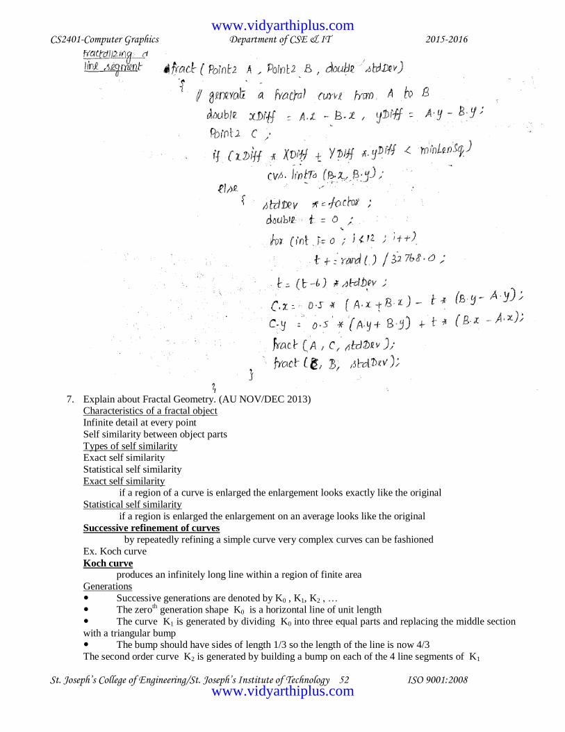
CS2401-Computer Graphics Department of CSE & IT 2015-2016
St. Joseph’s College of Engineering/St. Joseph’s Institute of Technology 52 ISO 9001:2008
7. Explain about Fractal Geometry. (AU NOV/DEC 2013)
Characteristics of a fractal object
Infinite detail at every point
Self similarity between object parts
Types of self similarity Exact self similarity
Statistical self similarity
Exact self similarity if a region of a curve is enlarged the enlargement looks exactly like the original
Statistical self similarity
if a region is enlarged the enlargement on an average looks like the original
Successive refinement of curves by repeatedly refining a simple curve very complex curves can be fashioned
Ex. Koch curve
Koch curve produces an infinitely long line within a region of finite area
Generations
Successive generations are denoted by K0 , K1, K2 , … The zero
th generation shape K0 is a horizontal line of unit length
The curve K1 is generated by dividing K0 into three equal parts and replacing the middle section
with a triangular bump The bump should have sides of length 1/3 so the length of the line is now 4/3
The second order curve K2 is generated by building a bump on each of the 4 line segments of K1
www.vidyarthiplus.com
www.vidyarthiplus.com

CS2401-Computer Graphics Department of CSE & IT 2015-2016
St. Joseph’s College of Engineering/St. Joseph’s Institute of Technology 53 ISO 9001:2008
Void drawKoch(double dir , double len , int n)
{ double dirRad = 0.0174533 * dir ; // direction in radians if ( n==0)
lineRel(len * Cos(dirRad) , len * Sin(dirRad));
else { n--; // reduce the order & length
len /=3; drawKoch(dir , len ,n);
dir += 60;
drawKoch(dir , len ,n); dir -= 120;
drawKoch(dir , len ,n);
dir += 60; drawKoch(dir , len ,n);
}
}
8. Discuss the ray tracing process with an example (AU NOV/DEC 2013 & MAY/JUNE 2014)
Ray Tracing / Ray Casting
- Provides a related , powerful approach to render scenes Overview of Ray Tracing Process
Pseudo code of a ray tracer:
for(int r = 0; r <nRows ; r++) for(int c = 0; c <nCols ; c++)
{
1. build the rc-th ray
2. find all intersections of the rc-th ray with objects in the scene 3. Identify the intersection that lies closest to and in front of the eye
4. Compute the hit point where the ray hits this object and the normal vector at that point
5. Find the color of the light returning to the eye along the ray from the point of intersection 6. place the color in the rc-th pixel
}
Intersection of a Ray with an Object
Common shapes used in ray tracing Sphere
Cylinder
Cone cube hex cone
If ‗S‘ is the starting point of a ray and ‗c‘ is its direction then the ray that intersects with a shape is given
by r(t) = S + ct // implicit form of shape is F(P)
Condition for r(t) to coincide with a point of the surface is
F(r(t)) = 0
The hit time thit can be found by solving F(S+ c thit ) = 0
Intersection of a Ray with the Generic Plane
generic plane – xy plane or z = 0 Implicit form is F(x ,y , z) = z
The ray S+ct intersects the generic plane when
Sz +czth = 0 , where th = - ( Sz / cz ) If cz = 0 , the ray is moving parallel to the plane & there is no intersection
Otherwise , the ray hits the plane at the point Phit = S – c(Sz / cz )
Intersection of a Ray with the Generic Shape
Consider a generic shape whose implicit form is F(P) = |P|2 – 1
www.vidyarthiplus.com
www.vidyarthiplus.com
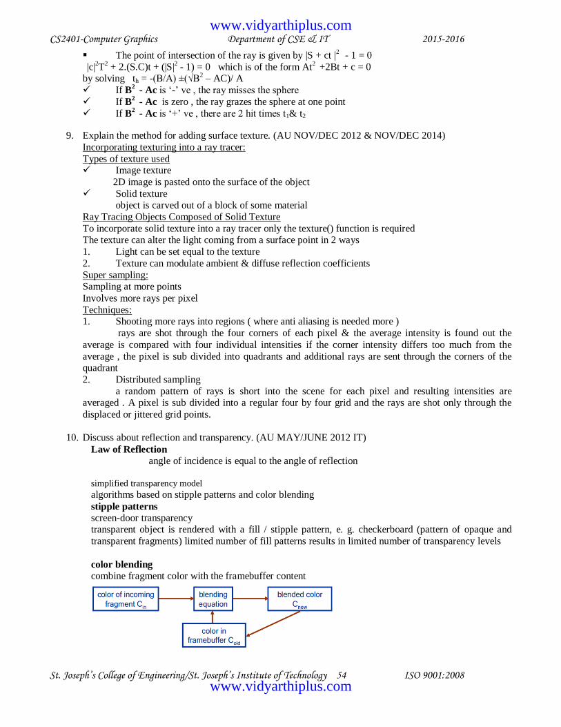
CS2401-Computer Graphics Department of CSE & IT 2015-2016
St. Joseph’s College of Engineering/St. Joseph’s Institute of Technology 54 ISO 9001:2008
The point of intersection of the ray is given by |S + ct |2
- 1 = 0
|c|2T
2 + 2.(S.C)t + (|S|
2 - 1) = 0 which is of the form At
2 +2Bt + c = 0
by solving th = -(B/A) ±(√B2 – AC)/ A
If B2 - Ac is ‗-‘ ve , the ray misses the sphere
If B2 - Ac is zero , the ray grazes the sphere at one point
If B2 - Ac is ‗+‘ ve , there are 2 hit times t1& t2
9. Explain the method for adding surface texture. (AU NOV/DEC 2012 & NOV/DEC 2014)
Incorporating texturing into a ray tracer:
Types of texture used Image texture
2D image is pasted onto the surface of the object
Solid texture object is carved out of a block of some material
Ray Tracing Objects Composed of Solid Texture
To incorporate solid texture into a ray tracer only the texture() function is required The texture can alter the light coming from a surface point in 2 ways
1. Light can be set equal to the texture
2. Texture can modulate ambient & diffuse reflection coefficients
Super sampling: Sampling at more points
Involves more rays per pixel
Techniques: 1. Shooting more rays into regions ( where anti aliasing is needed more )
rays are shot through the four corners of each pixel & the average intensity is found out the
average is compared with four individual intensities if the corner intensity differs too much from the
average , the pixel is sub divided into quadrants and additional rays are sent through the corners of the quadrant
2. Distributed sampling
a random pattern of rays is short into the scene for each pixel and resulting intensities are averaged . A pixel is sub divided into a regular four by four grid and the rays are shot only through the
displaced or jittered grid points.
10. Discuss about reflection and transparency. (AU MAY/JUNE 2012 IT)
Law of Reflection
angle of incidence is equal to the angle of reflection
simplified transparency model
algorithms based on stipple patterns and color blending
stipple patterns
screen-door transparency transparent object is rendered with a fill / stipple pattern, e. g. checkerboard (pattern of opaque and
transparent fragments) limited number of fill patterns results in limited number of transparency levels
color blending
combine fragment color with the framebuffer content
www.vidyarthiplus.com
www.vidyarthiplus.com

CS2401-Computer Graphics Department of CSE & IT 2015-2016
St. Joseph’s College of Engineering/St. Joseph’s Institute of Technology 55 ISO 9001:2008
alpha value
describes the opacity of a fragment, 1 - opaque, 0 - transparent stored together with RGB color in a 4D vector (RGBA)
blending equation for transparency
over operator αin = 0 - Cold
is not changed
αin = 1 - Cold is replaced by Cin
0 < αin < 1 - Cold
is replaced by a mix of Cin and Cold only the alpha value of the incoming fragment matters
11. Explain how refraction of light in a transparent object changes the view of the three dimensional object
(AU NOV/DEC 2013) Transparency of objects
transparency is the property of allowing light to pass through something.
An object that is transparent can be seen through. That is, what is on the other side of the object can be seen through it. The image you can see through a transparent object is similar to the image you can see
without it. It may be changed if the transparent object behaves like a lens. This could change the size or
shape of the image. Therefore, when someone says that an organization and its action should be "transparent", it is not the
right use of the term. What they actually mean is that these things should be more "visible".
If some light can be seen through an object but some of the detail of the image is lost, it is
a translucent material. The opposite of transparency is opacity. Refraction of light
Refraction is the change in direction of a wave due to a change in its transmission medium.
Refraction is essentially a surface phenomenon. The phenomenon is mainly in governance to the law of conservation of energy and momentum. Due to change of medium, the phase velocity of the wave is
changed but its frequency remains constant. This is most commonly observed when a wave passes from
one medium to another at any angle other than 90° or 0°. Refraction of light is the most commonly
observed phenomenon, but any type of wave can refract when it interacts with a medium, for example when sound waves pass from one medium into another or when water waves move into water of a
different depth. Refraction is described bySnell's law, which states that for a given pair of media and a
wave with a single frequency, the ratio of the sines of the angle of incidence θ1 and angle of refractionθ2 is equivalent to the ratio of phase velocities (v1 / v2) in the two media, or equivalently, to the
opposite ratio of the indices of refraction (n2 / n1):
12. Explain the Boolean operations on modeled objects to create new objects. (AU MAY/JUNE 2012 IT,
NOV/DEC 2013, MAY/JUNE 2014 & NOV/DEC 2014) Constructive solid geometry (CSG) is a technique used in solid modeling. Constructive solid geometry
allows a modeler to create a complex surface or object by using Boolean operators to combine objects.
Often CSG presents a model or surface that appears visually complex, but is actually little more than cleverly combined or decombined objects.
In 3D computer graphics and CAD CSG is often used in procedural modeling. CSG can also be
performed on polygonal meshes, and may or may not be procedural and/or parametric.
www.vidyarthiplus.com
www.vidyarthiplus.com

CS2401-Computer Graphics Department of CSE & IT 2015-2016
St. Joseph’s College of Engineering/St. Joseph’s Institute of Technology 56 ISO 9001:2008
The CSG union of two objects is the combined parts of the boundary from each that is not in the interior of the other object. To find the closest intersection of a ray with the union of the two spheres, we need to
find the closest intersection of either sphere such that it is not inside the other sphere. In the case above,
that would be the first intersection with A.
How can a ray tracer know this? One way is to shoot the ray at each of the sub-objects. Let the ray be defined parametricly as O~ + tD~ and let the nearest intersection with A be at t = tA where tA>minA and
the normal at the hitpoint be N~A, and similarly for B. Initially, minA and minB are both 0.
Note that the D~ · N~A < 0 at the nearest intersection with A. The surface normal points back along the direction of the ray. Since the object is closed and non-self intersecting, this means that O must have been
outside A. (Likewise, O~ is also outside B.) Since the intersection with A is the closer of the two, that is
the nearest intersection with the union. Now suppose that we instead shot the ray from inside the union, as shown in Figure 2:
Here the situation is more complicated. The intersection with B is closer than that with A, but D~ · N~A
> 0 is positive, meaning that the intersection with B is inside of A, so we must disallow it. In this case, we
can set minB to tB and shoot the ray at B again, this time finding the intersection on the far side of B.
The closest intersection is now with the far side of A, but D~ · N~B > 0 so the intersection with
A is on the interior of Band must again be disallowed. So as before, we can set minA to tA and
shoot again to consider the next intersection with A– this time, no intersection with A will be
found.
At this point, there are no more intersections with A, but there is one with the far side of B. Since
that intersection can‘tbe inside of A (if it were, we‘d still have an intersection with A to consider),
the intersection with the far side of B must bethe intersection with the union and so we return
it.Of course, if there was no intersection with either A or B, then there can‘t be an intersection
with their union.
www.vidyarthiplus.com
www.vidyarthiplus.com

CS2401-Computer Graphics Department of CSE & IT 2015-2016
St. Joseph’s College of Engineering/St. Joseph’s Institute of Technology 57 ISO 9001:2008
Boolean operations union, difference and intersection create objects rather than shapes.
When using Boolean operations, each object must have inside (i.e., interior) and outside (i.e., exterior). It is easy to understand the inside and outside of spheres, cones and tori; but, plans could be a problem.
Recall that normal vectors of a surface always point outward. In defining a plane, its normal vector
indicates the exterior. For example, the exterior of plane plane{ y, 0 } is the half-space above the xz-plane
and its interior is the half-space below the xz-plane. We only use POV-Ray's union { }, intersection { } and difference { }. POV-Ray also supports another
type union called merge { }, which could be very useful when constructing transparent objects. Older
version of POV-Ray even supports composite { }. But, for our purpose, union { }, intersect {
} and difference { }are sufficient.
www.vidyarthiplus.com
www.vidyarthiplus.com