unit iii heating and welding - rmd engineering college · 2019-05-23 · requirement of a good...
TRANSCRIPT
Prepared by :Mr.M.Venkateswaran AP/EEE, R.M.D Engineering college
UNIT III
HEATING AND WELDING
Prepared by :Mr.M.Venkateswaran AP/EEE, R.M.D Engineering college
Electric Heating
Electric heating is extensively used both for domestic and industrial applications.
Domestic applications include (i) room heaters (ii) immersion heaters for waterheating(iii)
hot plates for cooking (iv) electric kettles (v) electric irons (vi) popcornplants(vii) electric
ovens for bakeries and (viii) electric toasters etc.
Advantages of Electric Heating
(i) Cleanliness. Since neither dust nor ash is produced in electric heating, it is a clean
system of heating requiring minimum cost of cleaning. Moreover, the material to be
heated does not get contaminated.
(ii) No Pollution. Since no flue gases are produced in electric heating, no provisionhas to
be made for their exit.
(iii) Economical. Electric heating is economical because electric furnaces are cheaper in
their initial cost as well as maintenance cost since they do not require big space for
installation or for storage of coal and wood. Moreover, there is no need to construct
anychimney or to provide extra heat installation.
(iv) Ease of Control. It is easy to control and regulate the temperature of an electric
furnace with the help of manual or automatic devices. Temperature can be controlled
within ± 5°C which is not possible in any other form of heating.
(v) Special Heating Requirement. Special heating requirements such as uniformheating of
a material or heating one particular portion of the job without affecting its other parts
or heating with no oxidation can be met only by electric heating.
(vi) Higher Efficiency. Heat produced electrically does not go away waste through
thechimney and other by products. Consequently, most of the heat produced isutilised
for heating the material itself. Hence, electric heating has higher efficiency
ascompared to other types of heating.
(vii) Better working Conditions. Since electric heating produces no irritating noisesand
alsothe radiation losses are low, it results in low ambient temperature. Hence,working
with electric furnaces is convenient and cool.
(viii) Heating of Bad Conductors. Bad conductors of heat and electricity like wood,plastic
and bakery items can be uniformly and suitably heated with dielectric heatingprocess.

Prepared by :Mr.M.Venkateswaran AP/EEE, R.M.D Engineering college
(ix) Safety-Electric heating is quite safe because it responds quickly to the
controlledsignals.
(x) Lower Attention and Maintenance Cost. Electric heating equipment generally willnot
requiremuchattention and supervision and their maintenance cost is almostnegligible.
Hence, labour charges arenegligibly small as compared to other forms ofheating.
Different Methods of Heat Transfer
The different methods by which heat is transferred from a hotbody to a cold body are as
under:
Conduction
In this mode of heat transfer, one molecule of the body gets heatedand transfers some of the
heat to the adjacent molecule and so on.There is a temperature gradient between the two ends
of the bodybeing heated. Consider a solid material of cross-section Asq.m. andthickness x
metre as shown
Figure: Solid Material representing Heat Transfer Phenomenon
If T1 and T2 are the temperatures of the two sides of the slab in °K, where K is thermal
conductivity of the material.
Convection
In this process, heat is transferred by the flow of hot and cold air currents. Thisprocess is
applied in the heating of water by immersion heater or heating of buildings. The quantity of
heat absorbed by the body by convection process depends mainly on the temperature of the
heating element above the surroundings and upon the size of the surface of the heater. It also
depends, to some extent, on the positionof the heater. The amount of heat dissipated is
givenH = a (T1 - T2),where a and b are constants and T1 and T2 are the temperatures of the
heatingsurface and the fluid in °K respectively. In electric furnaces, heat transferred by
convection is negligible.
Radiation
Prepared by :Mr.M.Venkateswaran AP/EEE, R.M.D Engineering college
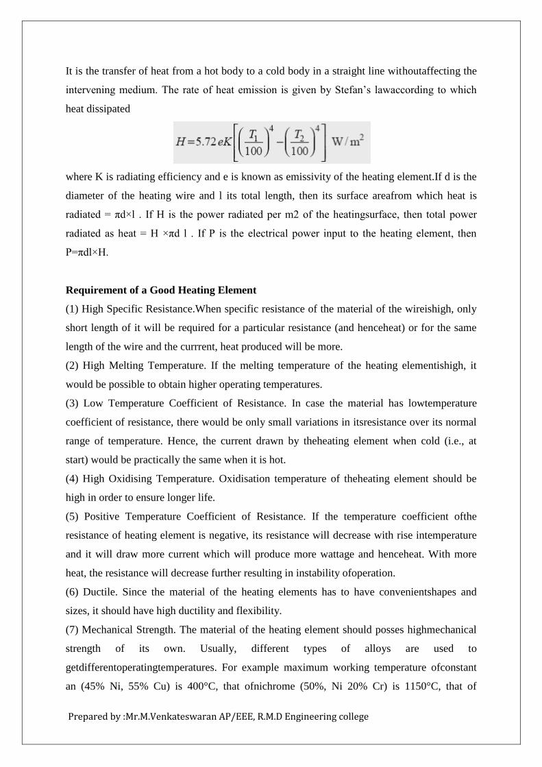
It is the transfer of heat from a hot body to a cold body in a straight line withoutaffecting the
intervening medium. The rate of heat emission is given by Stefan’s lawaccording to which
heat dissipated
where K is radiating efficiency and e is known as emissivity of the heating element.If d is the
diameter of the heating wire and l its total length, then its surface areafrom which heat is
radiated = πd×l . If H is the power radiated per m2 of the heatingsurface, then total power
radiated as heat = H ×πd l . If P is the electrical power input to the heating element, then
P=πdl×H.
Requirement of a Good Heating Element
(1) High Specific Resistance.When specific resistance of the material of the wireishigh, only
short length of it will be required for a particular resistance (and henceheat) or for the same
length of the wire and the currrent, heat produced will be more.
(2) High Melting Temperature. If the melting temperature of the heating elementishigh, it
would be possible to obtain higher operating temperatures.
(3) Low Temperature Coefficient of Resistance. In case the material has lowtemperature
coefficient of resistance, there would be only small variations in itsresistance over its normal
range of temperature. Hence, the current drawn by theheating element when cold (i.e., at
start) would be practically the same when it is hot.
(4) High Oxidising Temperature. Oxidisation temperature of theheating element should be
high in order to ensure longer life.
(5) Positive Temperature Coefficient of Resistance. If the temperature coefficient ofthe
resistance of heating element is negative, its resistance will decrease with rise intemperature
and it will draw more current which will produce more wattage and henceheat. With more
heat, the resistance will decrease further resulting in instability ofoperation.
(6) Ductile. Since the material of the heating elements has to have convenientshapes and
sizes, it should have high ductility and flexibility.
(7) Mechanical Strength. The material of the heating element should posses highmechanical
strength of its own. Usually, different types of alloys are used to
getdifferentoperatingtemperatures. For example maximum working temperature ofconstant
an (45% Ni, 55% Cu) is 400°C, that ofnichrome (50%, Ni 20% Cr) is 1150°C, that of
Prepared by :Mr.M.Venkateswaran AP/EEE, R.M.D Engineering college
Kantha(70% Fe, 25% Cr, 5% Al) is 1200° C and that of silicon carbide is 1450°C. With the
passage of time, every heating element breaks open and becomes unserviceable. Some of the
factors responsible for its failure are :
(1) Formation of hot spots which shine brighter during operation, (2) Oxidation (3)
Corrosion (4) Mechanical failure
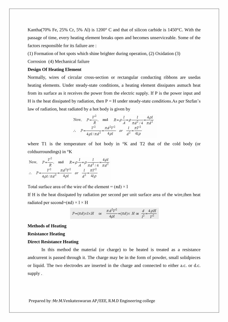
Design Of Heating Element
Normally, wires of circular cross-section or rectangular conducting ribbons are usedas
heating elements. Under steady-state conditions, a heating element dissipates asmuch heat
from its surface as it receives the power from the electric supply. If P is the power input and
H is the heat dissipated by radiation, then P = H under steady-state conditions.As per Stefan’s
law of radiation, heat radiated by a hot body is given by
where T1 is the temperature of hot body in °K and T2 that of the cold body (or
coldsurroundings) in °K
Total surface area of the wire of the element = (πd) × l
If H is the heat dissipated by radiation per second per unit surface area of the wire,then heat
radiated per second=(πd) × l × H
Methods of Heating
Resistance Heating
Direct Resistance Heating
In this method the material (or charge) to be heated is treated as a resistance
andcurrent is passed through it. The charge may be in the form of powder, small solidpieces
or liquid. The two electrodes are inserted in the charge and connected to either a.c. or d.c.
supply .
Prepared by :Mr.M.Venkateswaran AP/EEE, R.M.D Engineering college
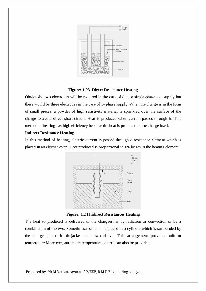
Figure: 1.23 Direct Resistance Heating
Obviously, two electrodes will be required in the case of d.c. or single-phase a.c. supply but
there would be three electrodes in the case of 3- phase supply. When the charge is in the form
of small pieces, a powder of high resistivity material is sprinkled over the surface of the
charge to avoid direct short circuit. Heat is produced when current passes through it. This
method of heating has high efficiency because the heat is produced in the charge itself.
Indirect Resistance Heating
In this method of heating, electric current is passed through a resistance element which is
placed in an electric oven. Heat produced is proportional to I2Rlosses in the heating element.
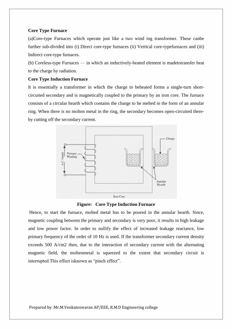
Figure: 1.24 Indirect Resistances Heating
The heat so produced is delivered to the chargeeither by radiation or convection or by a
combination of the two. Sometimes,resistance is placed in a cylinder which is surrounded by
the charge placed in thejacket as shown above. This arrangement provides uniform
temperature.Moreover, automatic temperature control can also be provided.
Prepared by :Mr.M.Venkateswaran AP/EEE, R.M.D Engineering college
Core Type Furnace
(a)Core-type Furnaces which operate just like a two wind ing transformer. These canbe
further sub-divided into (i) Direct core-type furnaces (ii) Vertical core-typefurnaces and (iii)
Indirect core-type furnaces.
(b) Coreless-type Furnaces — in which an inductively-heated element is madetotransfer heat
to the charge by radiation.
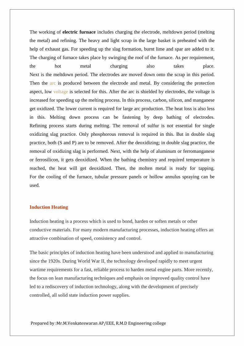
Core Type Induction Furnace
It is essentially a transformer in which the charge to beheated forms a single-turn short-
circuited secondary and is magnetically coupled to the primary by an iron core. The furnace
consists of a circular hearth which contains the charge to be melted in the form of an annular
ring. When there is no molten metal in the ring, the secondary becomes open-circuited there-
by cutting off the secondary current.
Figure: Core Type Induction Furnace
Hence, to start the furnace, molted metal has to be poured in the annular hearth. Since,
magnetic coupling between the primary and secondary is very poor, it results in high leakage
and low power factor. In order to nullify the effect of increased leakage reactance, low
primary frequency of the order of 10 Hz is used. If the transformer secondary current density
exceeds 500 A/cm2 then, due to the interaction of secondary current with the alternating
magnetic field, the moltenmetal is squeezed to the extent that secondary circuit is
interrupted.This effect isknown as “pinch effect”.
Prepared by :Mr.M.Venkateswaran AP/EEE, R.M.D Engineering college
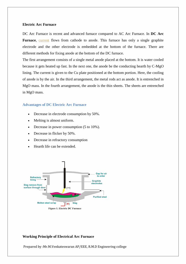
Electric Arc Furnace
DC Arc Furnace is recent and advanced furnace compared to AC Arc Furnace. In DC Arc
Furnace, current flows from cathode to anode. This furnace has only a single graphite
electrode and the other electrode is embedded at the bottom of the furnace. There are
different methods for fixing anode at the bottom of the DC furnace.
The first arrangement consists of a single metal anode placed at the bottom. It is water cooled
because it gets heated up fast. In the next one, the anode be the conducting hearth by C-MgO
lining. The current is given to the Cu plate positioned at the bottom portion. Here, the cooling
of anode is by the air. In the third arrangement, the metal rods act as anode. It is entrenched in
MgO mass. In the fourth arrangement, the anode is the thin sheets. The sheets are entrenched
in MgO mass.
Advantages of DC Electric Arc Furnace
Decrease in electrode consumption by 50%.
Melting is almost uniform.
Decrease in power consumption (5 to 10%).
Decrease in flicker by 50%.
Decrease in refractory consumption
Hearth life can be extended.
Working Principle of Electrical Arc Furnace
Prepared by :Mr.M.Venkateswaran AP/EEE, R.M.D Engineering college
The working of electric furnace includes charging the electrode, meltdown period (melting
the metal) and refining. The heavy and light scrap in the large basket is preheated with the
help of exhaust gas. For speeding up the slag formation, burnt lime and spar are added to it.
The charging of furnace takes place by swinging the roof of the furnace. As per requirement,
the hot metal charging also takes place.
Next is the meltdown period. The electrodes are moved down onto the scrap in this period.
Then the arc is produced between the electrode and metal. By considering the protection
aspect, low voltage is selected for this. After the arc is shielded by electrodes, the voltage is
increased for speeding up the melting process. In this process, carbon, silicon, and manganese
get oxidized. The lower current is required for large arc production. The heat loss is also less
in this. Melting down process can be fastening by deep bathing of electrodes.
Refining process starts during melting. The removal of sulfur is not essential for single
oxidizing slag practice. Only phosphorous removal is required in this. But in double slag
practice, both (S and P) are to be removed. After the deoxidizing; in double slag practice, the
removal of oxidizing slag is performed. Next, with the help of aluminum or ferromanganese
or ferrosilicon, it gets deoxidized. When the bathing chemistry and required temperature is
reached, the heat will get deoxidized. Then, the molten metal is ready for tapping.
For the cooling of the furnace, tubular pressure panels or hollow annulus spraying can be
used.
Induction Heating
Induction heating is a process which is used to bond, harden or soften metals or other
conductive materials. For many modern manufacturing processes, induction heating offers an
attractive combination of speed, consistency and control.
The basic principles of induction heating have been understood and applied to manufacturing
since the 1920s. During World War II, the technology developed rapidly to meet urgent
wartime requirements for a fast, reliable process to harden metal engine parts. More recently,
the focus on lean manufacturing techniques and emphasis on improved quality control have
led to a rediscovery of induction technology, along with the development of precisely
controlled, all solid state induction power supplies.
Prepared by :Mr.M.Venkateswaran AP/EEE, R.M.D Engineering college
What makes this heating method so unique? In the most common heating methods, a torch or
open flame is directly applied to the metal part. But with induction heating, heat is actually
"induced" within the part itself by circulating electrical currents.
Induction heating relies on the unique characteristics of radio frequency (RF) energy - that
portion of the electromagnetic spectrum below infrared and microwave energy. Since heat is
transferred to the product via electromagnetic waves, the part never comes into direct contact
with any flame, the inductor itself does not get hot (see Figure 1), and there is no product
contamination. When properly set up, the process becomes very repeatable and controllable.
How Induction Heating Works
How exactly does induction heating work? It helps to have a basic understanding of the
principles of electricity. When an alternating electrical current is applied to the primary of a
transformer, an alternating magnetic field is created. According to Faraday's Law, if the
secondary of the transformer is located within the magnetic field, an electric current will be
induced.
In a basic induction heating setup shown in Figure 2, a solid state RF power supply sends an
AC current through an inductor (often a copper coil),and the part to be heated (the workpiece)
is placed inside the inductor. The inductor serves as the transformer primary and the part to
be heated becomes a short circuit secondary. When a metal part is placed within the inductor
and enters the magnetic field, circulating eddy currents are induced within the part.
As shown in Figure 3, these eddy currents flow against the electrical resistivity of the metal,
generating precise and localized heat without any direct contact between the part and the
inductor. This heating occurs with both magnetic and non-magnetic parts, and is often
referred to as the "Joule effect", referring to Joule's first law – a scientific formula expressing
the relationship between heat produced by electrical current passed through a conductor.
Secondarily, additional heat is produced within magnetic parts through hysteresis – internal
friction that is created when magnetic parts pass through the inductor. Magnetic materials
naturally offer electrical resistance to the rapidly changing magnetic fields within the
inductor. This resistance produces internal friction which in turn produces heat.
Prepared by :Mr.M.Venkateswaran AP/EEE, R.M.D Engineering college
In the process of heating the material, there is therefore no contact between the inductor and
the part, and neither are there any combustion gases. The material to be heated can be located
in a setting isolated from the power supply; submerged in a liquid, covered by isolated
substances, in gaseous atmospheres or even in a vacuum.
Important Factors to Consider
The efficiency of an induction heating system for a specific application depends on several
factors: the characteristics of the part itself, the design of the inductor, the capacity of the
power supply, and the amount of temperature change required for the application.
The Characteristics of the Part
METAL OR PLASTIC
First, induction heating works directly only with conductive materials, normally metals.
Plastics and other non-conductive materials can often be heated indirectly by first heating a
conductive metal susceptor which transfers heat to the non-conductive material.
MAGNETIC OR NON-MAGNETIC
It is easier to heat magnetic materials. In addition to the heat induced by eddy currents,
magnetic materials also produce heat through what is called the hysteresis effect (described
above). This effect ceases to occur at temperatures above the "Curie" point - the temperature
at which a magnetic material loses its magnetic properties. The relative resistance of
magnetic materials is rated on a “permeability” scale of 100 to 500; while non-magnetics
have a permeability of 1, magnetic materials can have a permeability as high as 500.
THICK OR THIN
With conductive materials, about 85% of the heating effect occurs on the surface or "skin" of
the part; the heating intensity diminishes as the distance from the surface increases.So small
or thin parts generally heat more quickly than large thick parts, especially if the larger parts
need to be heated all the way through.
Research has shown a relationship between the frequency of the alternating current and the
heating depth of penetration: the higher the frequency, the shallower the heating in the part.
Frequencies of 100 to 400 kHz produce relatively high-energy heat, ideal for quickly heating
Prepared by :Mr.M.Venkateswaran AP/EEE, R.M.D Engineering college
small parts or the surface/skin of larger parts. For deep, penetrating heat, longer heating
cycles at lower frequencies of 5 to 30 kHz have been shown to be most effective.
RESISTIVITY
If you use the exact same induction process to heat two same size pieces of steel and copper,
the results will be quite different. Why? Steel – along with carbon, tin and tungsten – has
high electrical resistivity. Because these metals strongly resist the current flow, heat builds up
quickly. Low resistivity metals such as copper, brass and aluminum take longer to heat.
Resistivity increases with temperature, so a very hot piece of steel will be more receptive to
induction heating than a cold piece.
Inductor Design
It is within the inductor that the varying magnetic field required for induction heating is
developed through the flow of alternating current. So inductor design is one of the most
important aspects of the overall system. A well-designed inductor provides the proper heating
pattern for your part and maximizes the efficiency of the induction heating power supply,
while still allowing easy insertion and removal of the part.
Power Supply Capacity
The size of the induction power supply required for heating a particular part can be easily
calculated. First, one must determine how much energy needs to be transferred to the work-
piece. This depends on the mass of the material being heated, the specific heat of the
material, and the rise in temperature required. Heat losses from conduction, convection and
radiation should also be considered.
Degree of Temperature Change Required
Finally, the efficiency of induction heating for specific application depends on the amount of
temperature change required. A wide range of temperature changes can be accomodated; as a
rule of thumb, more induction heating power is generally utilized to increase the degree of
temperature change.
Prepared by :Mr.M.Venkateswaran AP/EEE, R.M.D Engineering college
Welding
It is the process of joining two pieces of metal or non-metal at faces rendered plastic
or liquid by the application of heat or pressure or both. Filler material may be used to effect
the union.
All welding processes fall into two distinct categories:
1. Fusion Welding—It involves melting of the parent metal. Examples are:
(i) Carbon arc welding, metal arc welding, electron beam welding, electro slagwelding and
electrogas welding which utilize electric energy and(ii) Gas welding and thermit welding
which utilize chemical energy for the meltingpurpose.
2. Non-fusion Welding—It does not involve melting of the parent metal. Examples are:
(i) Forge welding and gas non-fusion welding which use chemical energy.
(ii) Explosive welding, friction welding and ultrasonic welding etc.,which use mechanical
energy.
(iii) Resistance welding which uses electrical energy. Proper selection of the weldingprocess
depends on the (a) kind of metals to be joined (b) cost involved (c) nature ofproducts to be
fabricated and (d) production techniques adopted.
Use of Electricity in Welding
Electricity is used in welding for generating heat at the point of welding in order
tomelt the material which will subsequently fuse and form the actual weld joint. Thereare
many ways of producing this localised heat but the two most common methods are as follows
1. Resistance welding—here current is passed through the inherent resistance of thejoint to be
welded thereby generating the heat as per the equation I2 Rt/J kilocalories.
2. Arc welding—here electricity is conducted in the form of an arc which isestablished
between the two metallic surfaces
Arc Welding Machines
Welding is never done directly from the supply mains. Instead, special
weldingmachines are used which provided currents of various characteristics. Use of
suchmachines is essential for the following reasons
1. To convert a.c. supply into d.c. supply when d.c. welding is desired.
2. To reduce the high supply voltage to a safer and suitable voltage for weldingpurposes.
3. To provide high current necessary for arc welding withoutdrawing a corresponding high
current from the supply mains.
Prepared by :Mr.M.Venkateswaran AP/EEE, R.M.D Engineering college
4. To provide suitable voltage/current relationships necessary forarc welding at minimum
cost.
There are two general types of arc welding machines:
(a) d.c. welding machines
(i) motor-generator set
(ii) a.c. transformers with rectifiers
(b) a.c. welding machines
V-I Characteristics of Arc Welding DC Machines
It is found that during welding operation, large fluctuations in current andarc voltage
result from the mechanism of metal transfer and other factors. Thewelding machine must
compensate for such changes in arc voltage in order tomaintain an even arc column. There
are three major voltage/ current characteristicsused in modern d.c. welding machines which
help in controlling these currentfluctuations:
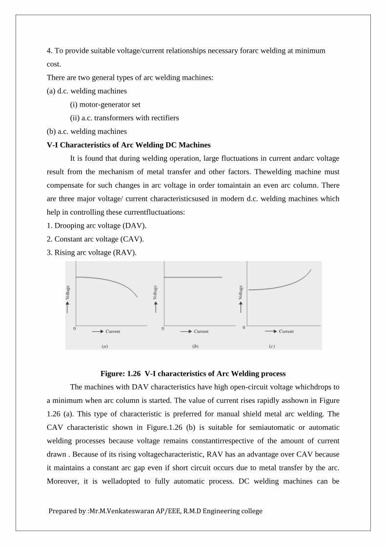
1. Drooping arc voltage (DAV).
2. Constant arc voltage (CAV).
3. Rising arc voltage (RAV).
Figure: 1.26 V-I characteristics of Arc Welding process
The machines with DAV characteristics have high open-circuit voltage whichdrops to
a minimum when arc column is started. The value of current rises rapidly asshown in Figure
1.26 (a). This type of characteristic is preferred for manual shield metal arc welding. The
CAV characteristic shown in Figure.1.26 (b) is suitable for semiautomatic or automatic
welding processes because voltage remains constantirrespective of the amount of current
drawn . Because of its rising voltagecharacteristic, RAV has an advantage over CAV because
it maintains a constant arc gap even if short circuit occurs due to metal transfer by the arc.
Moreover, it is welladopted to fully automatic process. DC welding machines can be
Prepared by :Mr.M.Venkateswaran AP/EEE, R.M.D Engineering college
controlled by a simple rheostat in the exciter circuit or by a combination of exciter regulator
and series of field taps. Some arcs welding are equipped with remote-controlled current units
enabling the operator to vary voltage amperage requirement without leaving themachines.
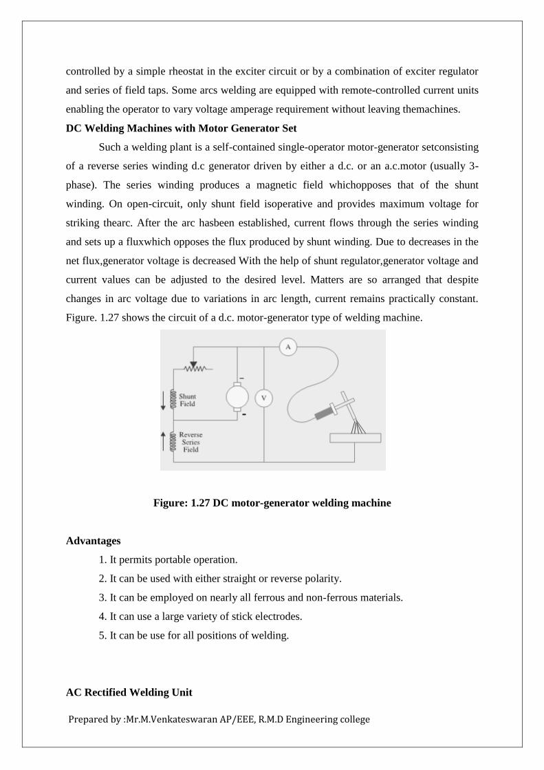
DC Welding Machines with Motor Generator Set
Such a welding plant is a self-contained single-operator motor-generator setconsisting
of a reverse series winding d.c generator driven by either a d.c. or an a.c.motor (usually 3-
phase). The series winding produces a magnetic field whichopposes that of the shunt
winding. On open-circuit, only shunt field isoperative and provides maximum voltage for
striking thearc. After the arc hasbeen established, current flows through the series winding
and sets up a fluxwhich opposes the flux produced by shunt winding. Due to decreases in the
net flux,generator voltage is decreased With the help of shunt regulator,generator voltage and
current values can be adjusted to the desired level. Matters are so arranged that despite
changes in arc voltage due to variations in arc length, current remains practically constant.
Figure. 1.27 shows the circuit of a d.c. motor-generator type of welding machine.
Figure: 1.27 DC motor-generator welding machine
Advantages
1. It permits portable operation.
2. It can be used with either straight or reverse polarity.
3. It can be employed on nearly all ferrous and non-ferrous materials.
4. It can use a large variety of stick electrodes.
5. It can be use for all positions of welding.
AC Rectified Welding Unit
Prepared by :Mr.M.Venkateswaran AP/EEE, R.M.D Engineering college
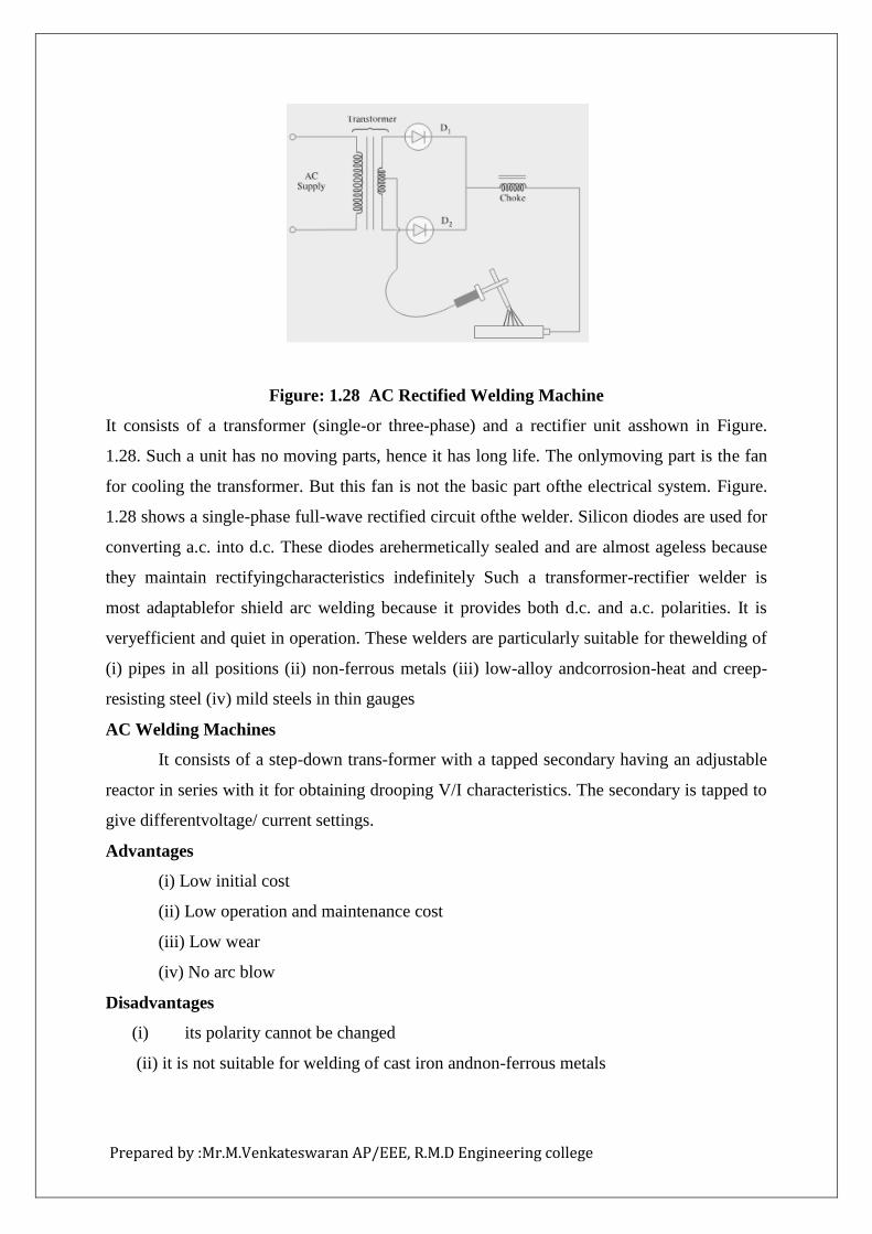
Figure: 1.28 AC Rectified Welding Machine
It consists of a transformer (single-or three-phase) and a rectifier unit asshown in Figure.
1.28. Such a unit has no moving parts, hence it has long life. The onlymoving part is the fan
for cooling the transformer. But this fan is not the basic part ofthe electrical system. Figure.
1.28 shows a single-phase full-wave rectified circuit ofthe welder. Silicon diodes are used for
converting a.c. into d.c. These diodes arehermetically sealed and are almost ageless because
they maintain rectifyingcharacteristics indefinitely Such a transformer-rectifier welder is
most adaptablefor shield arc welding because it provides both d.c. and a.c. polarities. It is
veryefficient and quiet in operation. These welders are particularly suitable for thewelding of
(i) pipes in all positions (ii) non-ferrous metals (iii) low-alloy andcorrosion-heat and creep-
resisting steel (iv) mild steels in thin gauges
AC Welding Machines
It consists of a step-down trans-former with a tapped secondary having an adjustable
reactor in series with it for obtaining drooping V/I characteristics. The secondary is tapped to
give differentvoltage/ current settings.
Advantages
(i) Low initial cost
(ii) Low operation and maintenance cost
(iii) Low wear
(iv) No arc blow
Disadvantages
(i) its polarity cannot be changed
(ii) it is not suitable for welding of cast iron andnon-ferrous metals

Prepared by :Mr.M.Venkateswaran AP/EEE, R.M.D Engineering college
Question Bank
PART - A
1. Define Mean Horizontal candle Power (MHCP):
2. Define Mean spherical Candle power (MSCP):
3. Define Mean Hemispherical candle power (MHSCP):
4. Define Reduction Factor:
5. What are the types of Lightning?
6. What are the Factors affecting the design of Illumination?
7. What are the Modes of Heat transfer?
8. What are the Properties of heating element Materials?
9. What are the Types of Electric Heating?
10. What are the Reasons for failure of heating element?
11. 11 What are the Application of Dielectric Heating?
12. What are the Advantages of Dielectric Heating?
13. What are the Advantages of Coated Electrodes?
14. What is Luminous efficiency?
15. What is Illumination and Luminous Intensity?
Prepared by :Mr.M.Venkateswaran AP/EEE, R.M.D Engineering college
PART - B
1. Explain the method of working of a Neon lamp with a neat sketch.
2. State the Lambert’s cosine law of illumination.
3. Explain the working of a sodium vapour lamp with in a neat sketch.
4. What is Halogen lamp?
5. Explain the types of lamps and lighting fitments you should select for
(i)A large machine shop with rows of drilling machines
(ii) A drawing office and lathes.
6. Explain the operation principle and working of a mercury vapour lamp and
compareitsperformance with a fluorescent lamp.
7. Describe with a neat sketch the principle ofoperation of a fluorescent lamp.
8. Mention the function of each component.
9. Explain the principle of street lighting? Show different types of lighting with
neat sketches.
10. Discuss about Diffusion principle of street lighting.
11. Explain coreless type induction furnace
12. Explain the construction and working principle of dielectric heating.
13. What are the types of ARC furnace? Describe the operation of them. (8)
14. Discuss the characteristic requirement of welding generator sets
(both AC and DC).

Prepared by :Mr.M.Venkateswaran AP/EEE, R.M.D Engineering college