unit ii advanced structural modeling
TRANSCRIPT
Unit II
Advanced Structural Modeling
A relationship is a connection among things. In object-oriented modeling, the four
most important relationships are dependencies, generalizations, associations, and
realizations.
Graphically, a relationship is rendered as a path, with different kinds of lines used to
distinguish the different relationships.
Dependency
A dependency is a using relationship, specifying that a change in the specification of
one thing may affect another thing that uses it, but not necessarily the reverse.
Graphically, a dependency is rendered as a dashed line
A plain, unadorned dependency relationship is sufficient for most of the using
relationships you'll encounter. However, if you want to specify a shade of meaning, the
UML defines a number of stereotypes that may be applied to dependency relationships.
There are 17 such stereotypes, all of which can be organized into six groups.
First, there are eight stereotypes that apply to dependency relationships among classes
and objects in class diagrams.
1 bind
Specifies that the source instantiates the target template using the given
actual parameters
2 derive Specifies that the source may be computed from the target
3 friend Specifies that the source is given special visibility into the target
4
instanceOf Specifies that the source object is an instance of the target classifier
5
instantiate Specifies that the source creates instances of the target
6
powertype
Specifies that the target is a powertype of the source; a powertype is a
classifier whose objects are all the children of a given parent
7 refine Specifies that the source is at a finer degree of abstraction than the target
8 use
Specifies that the semantics of the source element depends on the
semantics of the public part of the target
bind:
bind includes a list of actual arguments that map to the formal arguments of the
template.
derive
When you want to model the relationship between two attributes or two
associations, one of which is concrete and the other is conceptual.
friend
When you want to model relationships such as found with C++ friend classes.
instanceOf
When you want to model the relationship between a class and an object in the same
diagram, or between a class and its metaclass.
instantiate
when you want to specify which element creates objects of another.
powertype
when you want to model classes that cover other classes, such as you'll find when
modeling databases
refine
when you want to model classes that are essentially the same but at different levels
of abstraction.
use
when you want to explicitly mark a dependency as a using relationship
* There are two stereotypes that apply to dependency relationships among packages.
9 access
Specifies that the source package is granted the right to reference the
elements of the target package
10 import
A kind of access that specifies that the public contents of the target
package enter the flat namespace of the source, as if they had been
declared in the source
* Two stereotypes apply to dependency relationships among use cases:
11 extend Specifies that the target use case extends the behavior of the source
12 include
Specifies that the source use case explicitly incorporates the behavior of
another use case at a location specified by the source
* There are three stereotypes when modeling interactions among objects.
13 become
Specifies that the target is the same object as the source but at a later
point in time and with possibly different values, state, or roles
14 call Specifies that the source operation invokes the target operation
15 copy
Specifies that the target object is an exact, but independent, copy of the
source
* We'll use become and copy when you want to show the role, state, or attribute value of
one object at
different points in time or space
* You'll use call when you want to model the calling dependencies among operations.
* One stereotype you'll encounter in the context of state machines is
16 send Specifies that the source operation sends the target event
* We'll use send when you want to model an operation dispatching a given event to a target
object.
* The send dependency in effect lets you tie independent state machines together.
Finally, one stereotype that you'll encounter in the context of organizing the elements of
your system into subsystems and models is
17 trace Specifies that the target is an historical ancestor of the source
* We'll use trace when you want to model the relationships among elements in different
models
Generalization
A generalization is a relationship between a general thing (called the superclass or
parent) and a more specific kind of that thing(called the subclass or child).
In a generalization relationship, instances of the child may be used anywhere
instances of the parent apply—meaning that the child is substitutable for the parent.
A plain, unadorned generalization relationship is sufficient for most of the
inheritance relationships you'll encounter. However, if you want to specify a shade of
meaning,
The UML defines one stereotype and four constraints that may be applied to
generalization relationships.
1 implementation
Specifies that the child inherits the implementation of the parent
but does not make public nor support its interfaces, thereby
violating substitutability
implementation
We'll use implementation when you want to model private inheritance, such as
found in C++.
Next, there are four standard constraints that apply to generalization relationships
1 complete
Specifies that all children in the generalization have been specified in
the model and that no additional children are permitted
2 incomplete
Specifies that not all children in the generalization have been specified
(even if some are elided) and that additional children are permitted
3 disjoint
Specifies that objects of the parent may have no more than one of the
children as a type
4 overlapping
Specifies that objects of the parent may have more than one of the
children as a type
complete
We'll use the complete constraint when you want to show explicitly that you've
fully specified a hierarchy in the model (although no one diagram may show that
hierarchy);
incomplete
We'll use incomplete to show explicitly that you have not stated the full
specification of the hierarchy in the model (although one diagram may show
everything in the model).
Disjoint & overlapping
These two constraints apply only in the context of multiple inheritance.
We'll use disjoint and overlapping when you want to distinguish between static
classification (disjoint) and dynamic classification (overlapping).
Association
An association is a structural relationship, specifying that objects of one thing
are connected to objects of another.
We use associations when you want to show structural relationships.
There are four basic adornments that apply to an association: a name, the role at
each end of the association, the multiplicity at each end of the association, and aggregation.
For advanced uses, there are a number of other properties you can use to model
subtle details, such as
Navigation
Vision
Qualification
various flavors of aggregation.
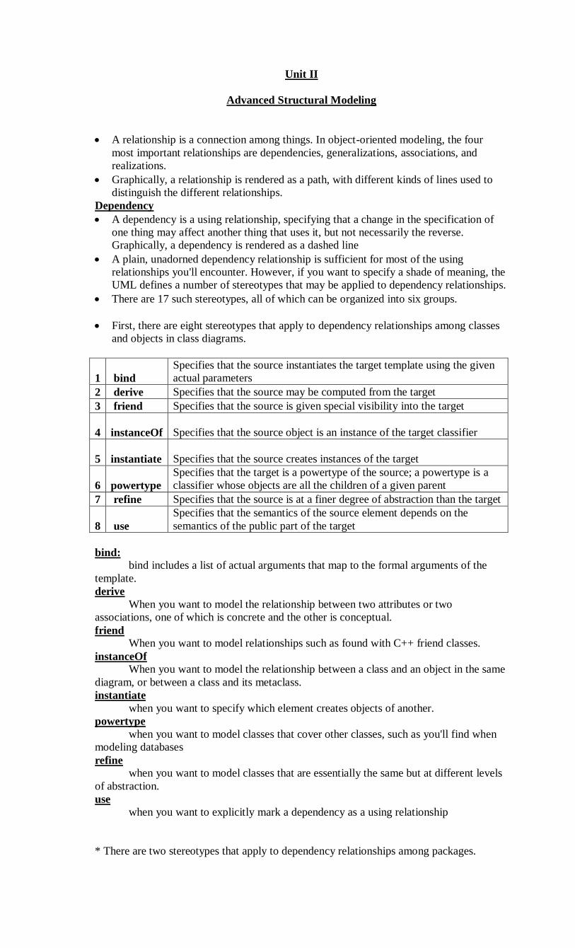
Navigation
unadorned association between two classes, such as Book and Library, it's possible to
navigate from objects of one kind to objects of the other kind. Unless otherwise
specified, navigation across an association is bidirectional.
However, there are some circumstances in which you'll want to limit navigation to just
one direction.
Navigation
Visibility
Given an association between two classes, objects of one class can see and navigate
to objects of the other, unless otherwise restricted by an explicit statement of
navigation.
However, there are circumstances in which you'll want to limit the visibility across
that association relative to objects outside the association.
In the UML, you can specify three levels of visibility for an association end, just as
you can for a class's features by appending a visibility symbol to a role name the
visibility of a role is public.

Private visibility indicates that objects at that end are not accessible to any objects
outside the association.
Protected visibility indicates that objects at that end are not accessible to any
objects outside the association, except for children of the other end.
Visibility
Qualification
In the context of an association, one of the most common modeling idioms you'll
encounter is the problem of lookup. Given an object at one end of an association, how do
you identify an object or set of objects at the other end?
In the UML, you'd model this idiom using a qualifier, which is an association
attribute whose values partition the set of objects related to an object across an association.
You render a qualifier as a small rectangle attached to the end of an association,
placing the attributes in the rectangle
Qualification
Interface Specifier
An interface is a collection of operations that are used to specify a service of a
class or a component
Collectively, the interfaces realized by a class represent a complete specification
of the behavior of that class.
However, in the context of an association with another target class, a source
class may choose to present only part of its face to the world
a Person class may realize many interfaces: IManager, IEmployee, IOfficer, and so
on
you can model the relationship between a supervisor and her workers with a one-to-
many
association, explicitly labeling the roles of this association as supervisor and
worker
In the context of this association, a Person in the role of supervisor presents only
the IManager face to the worker; a Person in the role of worker presents only the
IEmployee face to the supervisor. As the figure shows, you can explicitly show the
type of role using the syntax rolename : iname, where iname is some interface of
the other classifier.
Composition
* Simple aggregation is entirely conceptual and does nothing more than distinguish a
"whole" from a "part."
* Composition is a form of aggregation, with strong ownership and coincident lifetime as
part of the whole.
* Parts with non-fixed multiplicity may be created after the composite itself, but once
created they live and
die with it. Such parts can also be explicitly removed before the death of the composite.
* This means that, in a composite aggregation, an object may be a part of only one
composite at a time
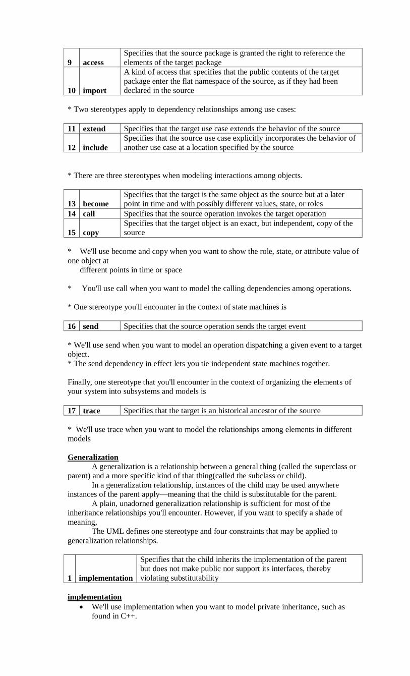
* In addition, in a composite aggregation, the whole is responsible for the disposition of
its parts, which
means that the composite must manage the creation and destruction of its parts
Composition
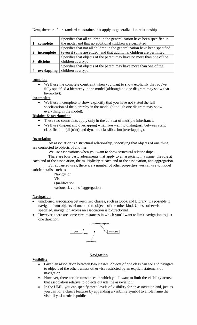
Association Classes
* In an association between two classes, the association itself might have properties.
* An association class can be seen as an association that also has class properties, or as a
class that also has
association properties.
* We render an association class as a class symbol attached by a dashed line to an
association
Association Classes
Constraints
* UML defines five constraints that may be applied to association relationships.
1 implicit
Specifies that the relationship is not manifest but, rather, is only
conceptual
2 ordered
Specifies that the set of objects at one end of an association are in an
explicit order
3 changeable Links between objects may be added, removed, and changed freely
4 addOnly
New links may be added from an object on the opposite end of the
association
5 frozen
A link, once added from an object on the opposite end of the
association, may not be modified or deleted
implicit
* if you have an association between two base classes, you can specify that same
association between two
children of those base classes
* you can specify that the objects at one end of an association (with a multiplicity greater
than one) are
ordered or unordered.
ordered
* For example, in a User/Password association, the Passwords associated with the User
might be kept in a
least-recently used order, and would be marked as ordered.
Finally, there is one constraint for managing related sets of associations:
1 xor Specifies that, over a set of associations, exactly one is manfest for each

associated object
Realization
1. Realization is sufficiently different from dependency, generalization, and association
relationships that it is treated as a separate kind of relationship.
2. A realizationis a semantic relationship between classifiers in which one classifier
specifies a contract that another classifier guarantees to carry out.
3. Graphically, a realization is rendered as a dashed directed line with a large open
arrowhead pointing to the classifier that specifies the contract.
4. You'll use realization in two circumstances: in the context of interfaces and in the
context of collaborations
5. Most of the time, you'll use realization to specify the relationship between an interface
and the class or component that provides an operation or service for it
6. You'll also use realization to specify the relationship between a use case and the
collaboration that realizes that use case
Realization of an Interface
Realization of a Use Case
Common Modeling Techniques
Modeling Webs of Relationships
1. When you model the vocabulary of a complex system, you may encounter dozens, if
not hundreds or thousands, of classes, interfaces, components, nodes, and use cases.
2. Establishing a crisp boundary around each of these abstractions is hard
3. This requires you to form a balanced distribution of responsibilities in the system as a
whole, with individual abstractions that are tightly cohesive and with relationships that
are expressive, yet loosely coupled
4. When you model these webs of relationships,
Don't begin in isolation. Apply use cases and scenarios to drive your discovery
of the relationships among a set of abstractions.
In general, start by modeling the structural relationships that are present. These
reflect the static view of the system and are therefore fairly tangible.
Next, identify opportunities for generalization/specialization relationships; use
multiple inheritance sparingly.
Only after completing the preceding steps should you look for dependencies;
they generally represent more-subtle forms of semantic connection.
For each kind of relationship, start with its basic form and apply advanced
features only as absolutely necessary to express your intent.
Remember that it is both undesirable and unnecessary to model all relationships
among a set of abstractions in a single diagram or view. Rather, build up your
system's relationships by considering different views on the system. Highlight
interesting sets of relationships in individual diagrams.
Interfaces, type and roles
Interface
An interface is a collection of operations that are used to specify a service of a class or
a component
type
A type is a stereotype of a class used to specify a domain of objects, together with the
operations (but not the methods) applicable to the object.
role
A role is the behavior of an entity participating in a particular context.
an interface may be rendered as a stereotyped class in order to expose its operations and
other properties.
Names
Every interface must have a name that distinguishes it from other interfaces.
A name is a textual string. That name alone is known as a simple name;
A path name is the interface name prefixed by the name of the package
Simple and Path Names
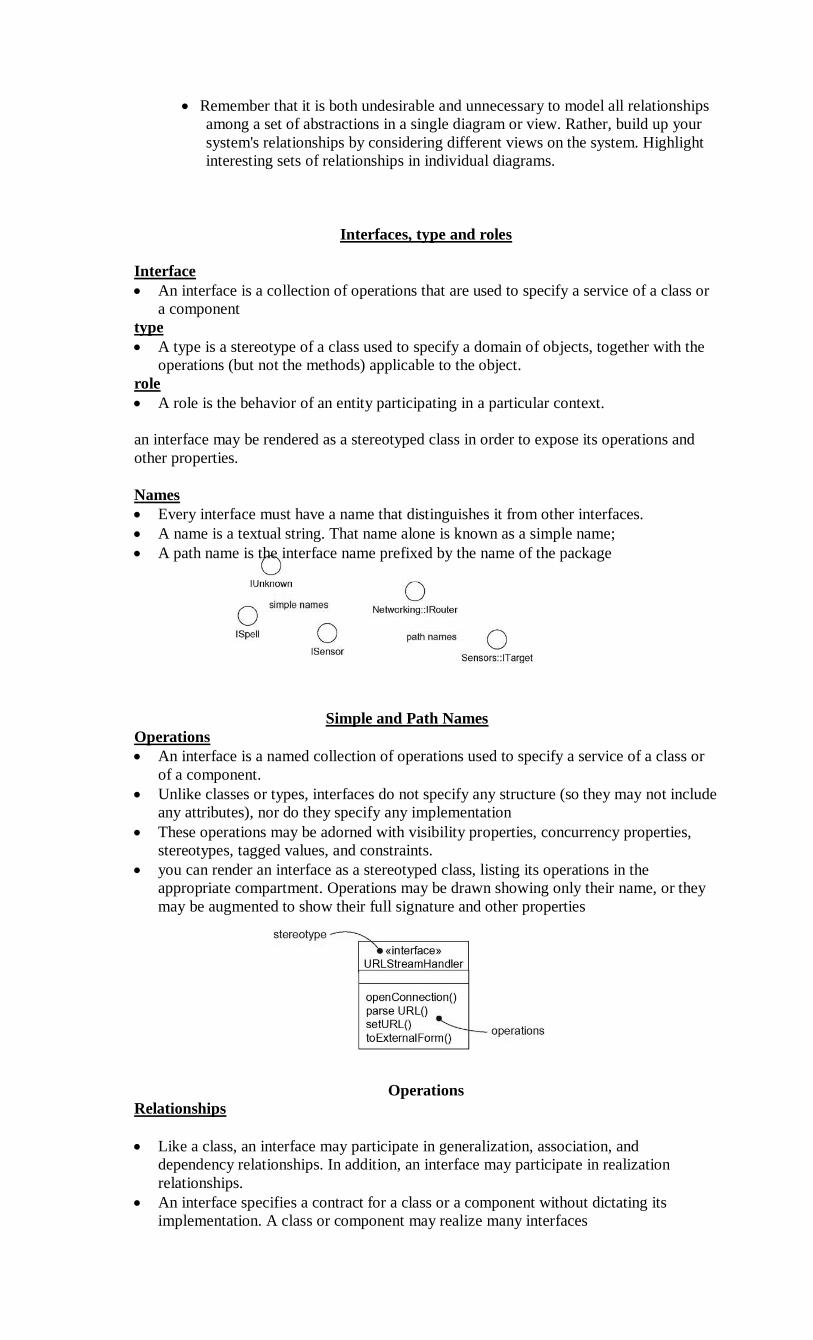
Operations
An interface is a named collection of operations used to specify a service of a class or
of a component.
Unlike classes or types, interfaces do not specify any structure (so they may not include
any attributes), nor do they specify any implementation
These operations may be adorned with visibility properties, concurrency properties,
stereotypes, tagged values, and constraints.
you can render an interface as a stereotyped class, listing its operations in the
appropriate compartment. Operations may be drawn showing only their name, or they
may be augmented to show their full signature and other properties
Operations
Relationships
Like a class, an interface may participate in generalization, association, and
dependency relationships. In addition, an interface may participate in realization
relationships.
An interface specifies a contract for a class or a component without dictating its
implementation. A class or component may realize many interfaces

We can show that an element realizes an interface in two ways.
o First, you can use the simple form in which the interface and its realization relationship
are
rendered as a lollipop sticking off to one side of a class or component.
o Second, you can use the expanded form in which you render an interface as a
stereotyped class,
which allows you to visualize its operations and other properties, and then draw a
realization
relationship from the classifier or component to the interface.
Realizations
Understanding an Interface
In the UML, you can supply much more information to an interface in order to make it
understandable and approachable.
First, you may attach pre- and postconditions to each operation and invariants to the
class or component as a whole. By doing this, a client who needs to use an interface
will be able to understand what the interface does and how to use it, without having to
dive into an implementation.
We can attach a state machine to the interface. You can use this state machine to
specify the legal partial ordering of an interface's operations.
We can attach collaborations to the interface. You can use collaborations to specify the
expected behavior of the interface through a series of interaction diagrams.
Types and Roles
A role names a behavior of an entity participating in a particular context. Stated
another way, a role is the face that an abstraction presents to the world.
For example, consider an instance of the class Person. Depending on the context,
that Person instance may play the role of Mother, Comforter, PayerOfBills, Employee,
Customer, Manager, Pilot, Singer, and so on. When an object plays a particular role, it
presents a face to the world, and clients that interact with it expect a certain behavior
depending on the role that it plays at the time.
an instance of Person in the role of Manager would present a different set of
properties than if the instance were playing the role of Mother.
In the UML, you can specify a role an abstraction presents to another abstraction
by adorning the name of an association end with a specific interface.
Roles
A class diagram like this one is useful for modeling the static binding of an abstraction
to its interface. You can model the dynamic binding of an abstraction to its interface by
using the become stereotype in an interaction diagram, showing an object changing
from one role to another.
If you want to formally model the semantics of an abstraction and its conformance to a
specific interface, you'll want to use the defined stereotype type
Type is a stereotype of class, and you use it to specify a domain of objects, together
with the operations (but not the methods) applicable to the objects of that type. The
concept of type is closely related to that of interface, except that a type's definition may
include attributes while an interface may not.
Common Modeling Techniques
Modeling the Seams in a Systemeling the Seams in a System
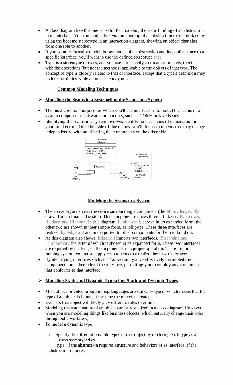
The most common purpose for which you'll use interfaces is to model the seams in a
system composed of software components, such as COM+ or Java Beans.
Identifying the seams in a system involves identifying clear lines of demarcation in
your architecture. On either side of those lines, you'll find components that may change
independently, without affecting the components on the other side,
Modeling the Seams in a System
The above Figure shows the seams surrounding a component (the library ledger.dll)
drawn from a financial system. This component realizes three interfaces: IUnknown,
ILedger, and IReports. In this diagram, IUnknown is shown in its expanded form; the
other two are shown in their simple form, as lollipops. These three interfaces are
realized by ledger.dll and are exported to other components for them to build on.
As this diagram also shows, ledger.dll imports two interfaces, IStreaming and
ITransaction, the latter of which is shown in its expanded form. These two interfaces
are required by the ledger.dll component for its proper operation. Therefore, in a
running system, you must supply components that realize these two interfaces.
By identifying interfaces such as ITransaction, you've effectively decoupled the
components on either side of the interface, permitting you to employ any component
that conforms to that interface.
Modeling Static and Dynamic Typeseling Static and Dynamic Types
Most object-oriented programming languages are statically typed, which means that the
type of an object is bound at the time the object is created.
Even so, that object will likely play different roles over time.
Modeling the static nature of an object can be visualized in a class diagram. However,
when you are modeling things like business objects, which naturally change their roles
throughout a workflow,
To model a dynamic type
o Specify the different possible types of that object by rendering each type as a
class stereotyped as
type (if the abstraction requires structure and behavior) or as interface (if the
abstraction requires

only behavior).
o Model all the roles the of the object may take on at any point in time. You can do
so in two ways:
1.) First, in a class diagram, explicitly type each role that the class plays in its
association with
Other classes. Doing this specifies the face instances of that class put on in
the context of the
associated object.
2.) Second, also in a class diagram, specify the class-to-type relationships using
generalization.
o In an interaction diagram, properly render each instance of the dynamically typed
class. Display
the role of the instance in brackets below the object's name.
o To show the change in role of an object, render the object once for each role it
plays in the
interaction, and connect these objects with a message stereotyped as become.
Modeling Static Types Modeling Dynamic Types
Package
“A package is a general-purpose mechanism for organizing elements into groups.”
Graphically, a package is rendered as a tabbed folder.
Names
Every package must have a name that distinguishes it from other packages. A name is a
textual string.
That name alone is known as a simple name; a path name is the package name prefixed
by the name of the package in which that package lives
We may draw packages adorned with tagged values or with additional compartments to
expose their details.
Simple and Extended Package
Owned Elements
A package may own other elements, including classes, interfaces, components,
nodes, collaborations, use cases, diagrams, and even other packages.
Owning is a composite relationship, which means that the element is declared in
the package. If the package is destroyed, the element is destroyed. Every element is
uniquely owned by exactly one package.

Elements of different kinds may have the same name within a package. Thus,
you can have a class named Timer, as well as a component named Timer, within the same
package.
Packages may own other packages. This means that it's possible to decompose
your models hierarchically.
We can explicitly show the contents of a package either textually or graphically.
Owned Elements
Visibility
You can control the visibility of the elements owned by a package just as you
can control the visibility of the attributes and operations owned by a class.
Typically, an element owned by a package is public, which means that it is
visible to the contents of any package that imports the element's enclosing package.
Conversely, protected elements can only be seen by children, and private
elements cannot be seen outside the package in which they are declared.
We specify the visibility of an element owned by a package by prefixing the
element's name with an appropriate visibility symbol.
Importing and Exporting
In the UML, you model an import relationship as a dependency adorned with the
stereotype import
Actually, two stereotypes apply here—import and access— and both specify that
the source package has access to the contents of the target.
Import adds the contents of the target to the source's namespace
Access does not add the contents of the target
The public parts of a package are called its exports.
The parts that one package exports are visible only to the contents of those
packages that explicitly import the package.
Import and access dependencies are not transitive
Importing and Exporting
Generalization
There are two kinds of relationships you can have between packages: import and
access dependencies used to import into one package elements exported from another and
generalizations, used to specify families of packages
Generalization among packages is very much like generalization among classes
Packages involved in generalization relationships follow the same principle of
substitutability as do classes. A specialized package (such as WindowsGUI) can be used
anywhere a more general package (such as GUI) is used

Generalization Among Packages
Standard Elements
o All of the UML's extensibility mechanisms apply to packages. Most often, you'll use
tagged values to add new package properties (such as specifying the author of a
package) and stereotypes to specify new kinds of packages (such as packages that
encapsulate operating system services).
o The UML defines five standard stereotypes that apply to packages
1. facade Specifies a package that is only a view on some other package
2. framework Specifies a package consisting mainly of patterns
3. stub Specifies a package that serves as a proxy for the public contents
of another package
4. subsystem Specifies a package representing an independent part of the entire
system being modeled
5. system Specifies a package representing the entire system being modeled
The UML does not specify icons for any of these stereotypes
Common Modeling Techniques
Modeling Groups of Elements
The most common purpose for which you'll use packages is to organize
modeling elements into groups that you can name and manipulate as a set.
There is one important distinction between classes and packages:
Packages have no identity (meaning that you can't have instances of packages,
so they are invisible in the running system);
classes do have identity (classes have instances, which are elements of a running
system).
To model groups of elements,
Scan the modeling elements in a particular architectural view and look for clumps
defined by elements that are conceptually or semantically close to one another.
Surround each of these clumps in a package.
For each package, distinguish which elements should be accessible outside the
package. Mark them public, and all others protected or private. When in doubt, hide the
element.
Explicitly connect packages that build on others via import dependencies
In the case of families of packages, connect specialized packages to their more
general part via generalizations
Modeling Architectural Views
o We can use packages to model the views of an architecture.
o Remember that a view is a projection into the organization and structure of a system,
focused on a particular aspect of that system.
o This definition has two implications. First, you can decompose a system into almost
orthogonal packages, each of which addresses a set of architecturally significant
decisions.( design view, a process view, an implementation view, a deployment view,
and a use case view)
o Second, these packages own all the abstractions germane to that view.(Implementation
view)
o To model architectural views,
o Identify the set of architectural views that are significant in the context of your
problem. In
practice, this typically includes a design view, a process view, an
implementation view, a
deployment view, and a use case view.

o Place the elements (and diagrams) that are necessary and sufficient to visualize,
specify, construct,
and document the semantics of each view into the appropriate package.
o As necessary, further group these elements into their own packages.
o There will typically be dependencies across the elements in different views. So,
in general, let each
view at the top of a system be open to all others at that level.
Modeling Architectural Views
Instances
An instance is a concrete manifestation of an abstraction to which a set of operations
can be applied and which has a state that stores the effects of the operations.
Graphically, an instance is rendered by underlining its name.
Abstractions and Instances
Most instances you'll model with the UML will be instances of classes although you
can have instances of other things, such as components, nodes, use cases, and
associations
In the UML, an instance is easily distinguishable from an abstraction. To indicate an
instance, you underline its name.
We can use the UML to model these physical instances, but you can also model things
that are not so concrete.
Named, Anonymous, Multiple, and Orphan Instances
Names
Every instance must have a name that distinguishes it from other instances within its
context.
Typically, an object lives within the context of an operation, a component, or a node.
A name is a textual string. That name alone is known as a simple name. or it may be a
path name
Operations
The operations you can perform on an object are declared in the object's abstraction
For example, if the class Transaction defines the operation commit, then given the
instance t : Transaction, you can write expressions such as t.commit()

State
An object also has state. An object's state is therefore dynamic. So when you
visualize its state, you are really specifying the value of its state at a given moment in time
and space.
It's possible to show the changing state of an object by showing it multiple times
in the same interaction diagram, but with each occurrence representing a different state.
When you operate on an object, you typically change its state;
when you query an object, you don't change its state
Other Features
Processes and threads are an important element of a system's process view, so
the UML provides a visual cue to distinguish elements that are active from those that are
passive.
You can declare active classes that reify a process or thread, and in turn you can
distinguish an instance of an active class
Active Objects
There are two other elements in the UML that may have instances
The first is a link. A link is a semantic connection among objects. An instance of an
association is therefore a link. A link is rendered as a line
The second is a class-scoped attribute and operation. A class-scoped feature is in effect
an object in the class that is shared by all instances of the class.
Standard Elements
All of the UML's extensibility mechanisms apply to objects. Usually, however, you
don't stereotype an instance directly, nor do you give it its own tagged values. Instead,
an object's stereotype and tagged values derive from the stereotype and tagged values
of its associated abstraction.
Stereotyped Objects
The UML defines two standard stereotypes that apply to the dependency relationships
among objects and among classes:
1. instanceOf Specifies that the client object is an instance of the supplier classifier
2. instantiate Specifies that the client class creates instances of the supplier class
There are also two stereotypes related to objects that apply to messages and transitions:

1. become Specifies that the client is the same object as the supplier, but at a later
time and with possibly different values, state, or roles
2. copy Specifies that the client object is an exact but independent copy of the
supplier
The UML defines a standard constraint that applies to objects:
transient Specifies that an instance of the role is created during execution of the
enclosing interaction but is destroyed before completion of execution
Common Modeling Techniques
Modeling Concrete Instances
When you model concrete instances, you are in effect visualizing things that live in the
real world
One of the things for which you'll use objects is to model concrete instances that exist
in the real world
To model concrete instances,
Identify those instances necessary and sufficient to visualize, specify, construct, or
document the problem you are modeling.
Render these objects in the UML as instances. Where possible, give each object a
name. If there is no meaningful name for the object, render it as an anonymous
object.
Expose the stereotype, tagged values, and attributes (with their values) of each
instance necessary and sufficient to model your problem.
Render these instances and their relationships in an object diagram or other
diagram appropriate to the kind of the instance.
Modeling Concrete Instances
Modeling Prototypical Instances
Perhaps the most important thing for which you'll use instances is to model the
dynamic interactions among objects. When you model such interactions, you are
generally not modeling concrete instances that exist in the real world.
These are prototypical objects and, therefore, are roles to which concrete instances
conform.
Concrete objects appear in static places, such as object diagrams, component
diagrams, and deployment diagrams.
Prototypical objects appear in such places as interaction diagrams and activity
diagrams.
To model prototypical instances,
Identify those prototypical instances necessary and sufficient to visualize,
specify, construct, or document the problem you are modeling.
Render these objects in the UML as instances. Where possible, give each object
a name. If there is no meaningful name for the object, render it as an
anonymous object.
Expose the properties of each instance necessary and sufficient to model your
problem.

Render these instances and their relationships in an interaction diagram or an
activity diagram.
CLASS DIAGRAMS
Class diagrams are the most common diagram found in modeling object-oriented systems.
A class diagram shows a set of classes, interfaces, and collaborations and their
relationships.
Class diagrams are important not only for visualizing, specifying, and documenting
structural models, but also for constructing executable systems through forward and
reverse engineering.
Building software has much the same characteristics except that, given the fluidity of
software, we have the ability to define your own basic building blocks from scratch. With
the UML, you use class diagrams to visualize the static aspects of these building blocks
and their relationships and to specify their details for construction, as you can see in Figure
.
Common Properties
A class diagram is just a special kind of diagram and shares the same common properties
as do all other diagrams name and graphical content that are a projection into a model.
What distinguishes a class diagram from other kinds of diagrams is its particular content.
Class diagrams commonly contain the following things:
• Classes
• Interfaces
• Collaborations

• Dependency, generalization, and association relationships
Like all other diagrams, class diagrams may contain notes and constraints.
Class diagrams may also contain packages or subsystems, both of which are used to group
elements of your model into larger chunks. Sometimes you'll want to place instances in
class diagrams as well, especially when we want to visualize the (possibly dynamic) type
of an instance.
Common Uses
Use class diagrams to model the static design view of a system. This view primarily
supports the functional requirements of a system the services the system should provide to
its end users.
When you model the static design view of a system, you'll typically use class diagrams in
one of three ways.
1. To model the vocabulary of a system
Modeling the vocabulary of a system involves making a decision about which abstractions
are a part of the system under consideration and which fall outside its boundaries. You use
class
diagrams to specify these abstractions and their responsibilities.
2. To model simple collaborations
A collaboration is a society of classes, interfaces, and other elements that work together to
provide some cooperative behavior that's bigger than the sum of all the elements. For
example,
when you re modeling the semantics of a transaction in a distributed system, you can't just
stare
at a single class to understand what's going on. Rather, these semantics are carried out by a
set of
classes that work together. You use class diagrams to visualize and specify this set of
classes and
their relationships.
3. To model a logical database schema
Think of a schema as the blueprint for the conceptual design of a database. In many
domains, we want to store persistent information in a relational database or in an object-
oriented database. We can model schemas for these databases using class diagrams.
COMMON MODELING TECHNIQUES
Modeling Simple Collaborations
No class stands alone. Rather, each works in collaboration with others to carry out some
semantics greater than each individual. Therefore, in addition to capturing the vocabulary
of your system, you'll also need to turn your attention to visualizing, specifying,
constructing, and documenting the various ways these things in your vocabulary work
together. Weuse class diagrams to represent such collaborations.
To model a collaboration,
• Identify the mechanism you'd like to model. A mechanism represents some function or
behavior of the part of the system you are modeling that results from the interaction of a
society of classes, interfaces, and other things.
• For each mechanism, identify the classes, interfaces, and other collaborations that
participate in this collaboration. Identify the relationships among these things as well.
• Use scenarios to walk through these things. Along the way, you'll discover parts of your
model that were missing and parts that were just plain semantically wrong.
• Be sure to populate these elements with their contents. For classes, start with getting a
good balance of responsibilities. Then, over time, turn these into concrete attributes and
operations.
For example, Figure shows a set of classes drawn from the implementation of an
autonomous robot. The figure focuses on the classes involved in the mechanism for
moving the robot along a path. You'll find one abstract class (Motor) with two concrete
children, SteeringMotor and MainMotor. Both of these classes inherit the five operations
of their parent, Motor. The two classes are, in turn, shown as parts of another class, Driver.
The class PathAgent has a one-to-one association to Driver and a one-to-many association

to CollisionSensor. No attributes or operations are shown for PathAgent, although its
responsibilities are given.
MODELING A LOGICAL DATABASE SCHEMA
Many of the systems you'll model will have persistent objects, which means that they can
be stored in a database for later retrieval. Most often, you'll use a relational database, an
objectoriented database, or a hybrid object/relational database for persistent storage. The
UML is wellsuited to modeling logical database schemas, as well as physical databases
themselves.
The UML's class diagrams are a superset of entity-relationship (E-R) diagrams, a common
modeling tool for logical database design. Whereas classical E-R diagrams focus only on
data, class diagrams go a step further by permitting the modeling of behavior as well. In
the physical database, these logical operations are generally turned into triggers or stored
procedures.
To model a schema,
Identify those classes in your model whose state must transcend the lifetime of their
applications.
• Create a class diagram that contains these classes. You can define your own set of
stereotypes and tagged values to address database-specific details.
• Expand the structural details of these classes. In general, this means specifying the details
of their attributes and focusing on the associations and their multiplicities that relate these
classes.
• Watch for common patterns that complicate physical database design, such as cyclic
associations and one-to-one associations. Where necessary, create intermediate
abstractions to simplify your logical structure.
• Consider also the behavior of these classes by expanding operations that are important for
data access and data integrity.
The Figure shows a set of classes drawn from an information system for a school.
We find the classes named Student, Course, and Instructor. There's an association between
Student and Course, specifying that students attend courses. Furthermore, every student
may attend any number of courses, and every course may have any number of students.
Figure: Modeling a Schema

FORWARD AND REVERSE ENGINEERING
For some uses of the UML, the models we create will never map to code. For example, if
you are modeling a business process using activity diagrams, many of the activities we
model will involve people, not computers. In other cases, you'll want to model systems
whose parts are, from your level of abstraction, just a piece of hardware.
Forward engineering is the process of transforming a model into code through a mapping
to an implementation language. Forward engineering results in a loss of information,
because models written in the UML are semantically richer than any current object-
oriented programming language. In fact, this is a major reason why you need models in
addition to code.
Structural features, such as collaborations, and behavioral features, such as interactions,
can be visualized clearly in the UML, but not so clearly from raw code.
To forward engineer a class diagram,
• Identify the rules for mapping to your implementation language or languages of choice.
This is something you'll want to do for your project or your organization as a whole.
• Depending on the semantics of the languages you choose, you may want to constrain
your use of certain UML features. For example, the UML permits you to model multiple
inheritance, but Smalltalk permits only single inheritance.
• Use tagged values to guide implementation choices in your target language. You can do
this at the level of individual classes if you need precise control. You can also do so at a
higher level, such as with collaborations or packages.
• Use tools to generate code.
Figure: Forward Engineering

Reverse engineering is the process of transforming code into a model through a mapping
from a specific implementation language. Reverse engineering results in a flood of
information, some of which is at a lower level of detail than you'll need to build useful
models. At the same time, reverse engineering is incomplete.
To reverse engineer a class diagram,
• Identify the rules for mapping from your implementation language or languages of
choice. This is something you'll want to do for your project or your organization as a
whole.
• Using a tool, point to the code you'd like to reverse engineer. Use your tool to generate a
new model or modify an existing one that was previously forward engineered. It is
unreasonable to expect to reverse engineer a single concise model from a large body of
code. You need to select portion of the code and build the model from the bottom.
• Using your tool, create a class diagram by querying the model. For example, you might
start with one or more classes, then expand the diagram by following specific relationships
or other neighboring classes. Expose or hide details of the contents of this class diagram as
necessary to communicate your intent.
• Manually add design information to the model to express the intent of the design that is
missing or hidden in the code.
OBJECT DIAGRAMS
Object diagrams model the instances of things contained in class diagrams. An object
diagram shows a set of objects and their relationships at a point in time.
We use object diagrams to model the static design view or static process view of a system.
This involves modeling a snapshot of the system at a moment in time and rendering a set
of objects, their state, and their relationships.
Object diagrams are not only important for visualizing, specifying, and documenting
structural models, but also for constructing the static aspects of systems through forward
and reverse engineering.
An object diagram covers a set of instances of the things found in a class diagram. An
object diagram,
therefore, expresses the static part of an interaction, consisting of the objects that
collaborate but without any of the messages passed among them. In both cases, an object
diagram freezes a moment in time, as in Figure .
Figure. An Object Diagram
An object diagram is a diagram that shows a set of objects and their relationships at a point
in time. Graphically, an object diagram is a collection of vertices and arcs.
Common Properties
An object diagram is a special kind of diagram and shares the same common properties as
all other diagrams that is, a name and graphical contents that are a projection into a model.

What distinguishes an object diagram from all other kinds of diagrams is its particular
content.
Contents
Object diagrams commonly contain
• Objects
• Links
Like all other diagrams, object diagrams may contain notes and constraints.
COMMON MODELING TECHNIQUES
Modeling Object Structures
When you construct a class diagram, a component diagram, or a deployment diagram, what
we are doing is capturing a set of abstractions that are interesting to you as a group and, in
that context, exposing their semantics and their relationships to other abstractions in the
group.
If class A has a one-to-many association to class B, then for one instance of A there might
be five instances of B; for another instance of A there might be only one instance of B.
Furthermore, at a given moment in time, that instance of A, along with the related
instances of B, will each have certain values for their attributes and state
machines.
To model an object structure,
Identify the mechanism you'd like to model. A mechanism represents some function or
behavior of the part of the system you are modeling that results from the interaction of a
society of classes, interfaces, and other things.
• Create a collaboration to describe a mechanism.
• For each mechanism, identify the classes, interfaces, and other elements that participate
in this collaboration; identify the relationships among these things as well.
• Consider one scenario that walks through this mechanism. Freeze that scenario at a
moment in time, and render each object that participates in the mechanism.
• Expose the state and attribute values of each such object, as necessary, to understand the
scenario.
• Similarly, expose the links among these objects, representing instances of associations
among them.
Figure : Modeling Object Structures
FORWARD AND REVERSE ENGINEERING
Forward engineering (the creation of code from a model) an object diagram is theoretically
possible but pragmatically of limited value. In an object-oriented system, instances are
things that are created and destroyed by the application during run time. Therefore, you
cannot exactly instantiate these objects from the outside.
Reverse engineering (the creation of a model from code) an object diagram can be
useful.In fact, while you are debugging your system, this is something that you or your
tools will do all the time.
To reverse engineer an object diagram,

• Chose the target you want to reverse engineer. Typically, you'll set your context inside an
operation or relative to an instance of one particular class.
• Using a tool or simply walking through a scenario, stop execution at a certain moment in
time.
• Identify the set of interesting objects that collaborate in that context and render them in
an object diagram.
• As necessary to understand their semantics, expose these object's states.
• As necessary to understand their semantics, identify the links that exist among these
objects.
• If your diagram ends up overly complicated, prune it by eliminating objects that are not
germane to the questions about the scenario you need answered. If your diagram is too
simplistic, expand the neighbors of certain interesting objects and expose each object's
state more deeply.