unit - i course material - sathyabama university · non-coplanar concurrent forces all forces do...
TRANSCRIPT
COURSE MATERIALUNIT - I
MECHANICS OF STRUCTURES SCI 1105
Engineering Mechanics
• Branch of science which deals with the behavior of a body with the state of rest or motion, subjected to the action of forces.
• Much of modern engineering mechanics is based on Issac Newton’s Laws of motion while the modern practice of their application can be traced back to Stephen Timoshenko, who is said to be the father of modern engineering mechanics.

Applied mechanics
• Branch of engineering mechanics which deals with the study of different laws of mechanics as applied to the solution of engineering problems.
• The advances and research in Applied Mechanics has wide application in many departments. Some of the departments that put the subject into practice are Civil Engineering, Mechanical Engineering, Construction Engineering, Materials Science and Engineering, Aerospace Engineering, Chemical Engineering, Electrical Engineering, Nuclear Engineering, Structural Engineering and Bioengineering.
● Applied mechanics examines the response of bodies (solids and fluids) or systems of bodies to external forces.
Some examples of mechanical systems include ● the flow of a liquid under pressure, ● the fracture of a solid from an applied force, or ● the vibration of an ear in response to sound.
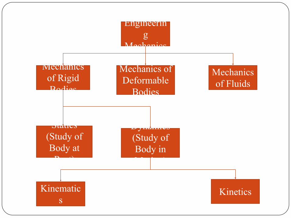
Engineering
Mechanics
Mechanics of Deformable
Bodies
Mechanics of Fluids
Mechanics of Rigid Bodies
Statics (Study of Body at
Rest)
Dynamics (Study of Body in Motion)
Kinematics
Kinetics

Rigid Body
• It is composed of large number of particles, which occupy fixed positions with respect to each other before and after applying load.
• Relative distances of its particles remains invariable.
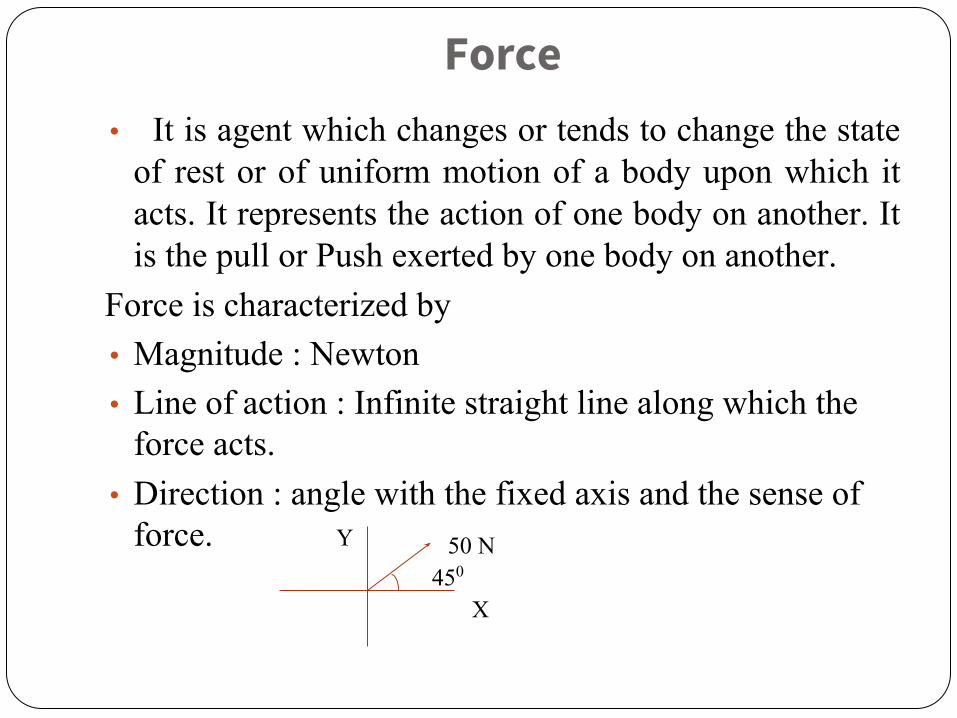
Force• It is agent which changes or tends to change the state
of rest or of uniform motion of a body upon which it acts. It represents the action of one body on another. It is the pull or Push exerted by one body on another.
Force is characterized by• Magnitude : Newton• Line of action : Infinite straight line along which the
force acts.• Direction : angle with the fixed axis and the sense of
force.450
50 N
X
Y
Force system ● When several forces act simultaneously on a body,
they constitute a system of forces Types of Force System:1. Coplanar Force
Force in Plane2. Non – Coplanar Force
Force in Space

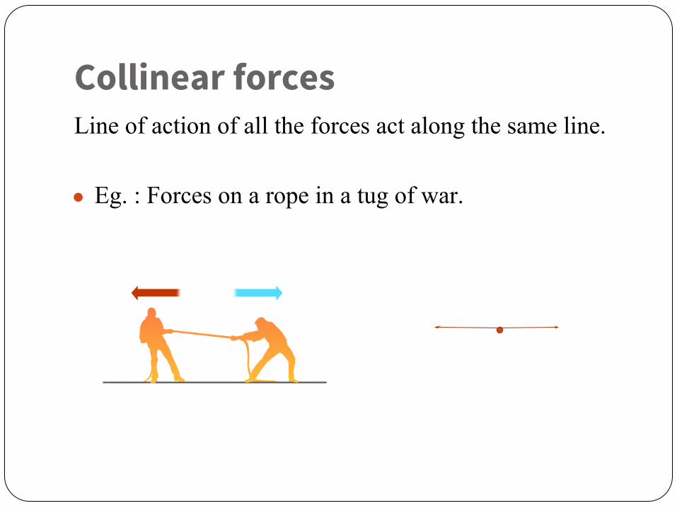
Collinear forcesLine of action of all the forces act along the same line.
● Eg. : Forces on a rope in a tug of war.
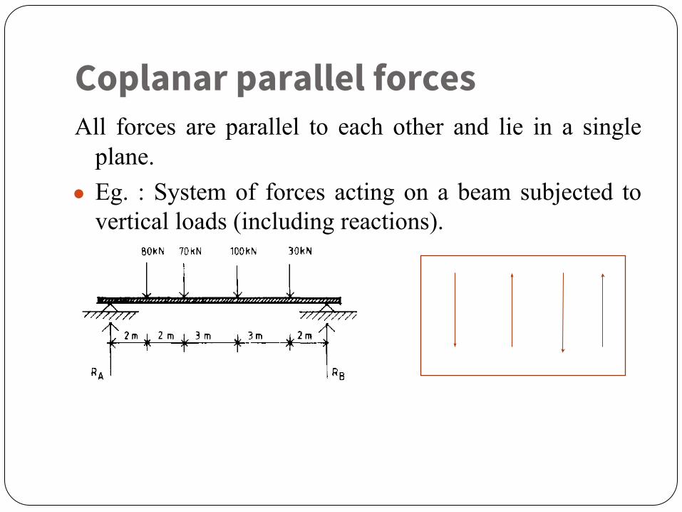
Coplanar parallel forcesAll forces are parallel to each other and lie in a single
plane. ● Eg. : System of forces acting on a beam subjected to
vertical loads (including reactions).

Coplanar like parallel ForcesAll forces are parallel to each other, lie in a single plane
and are acting in the same direction. ● Eg. : Weight of a stationary train on a rail when the
track is straight.
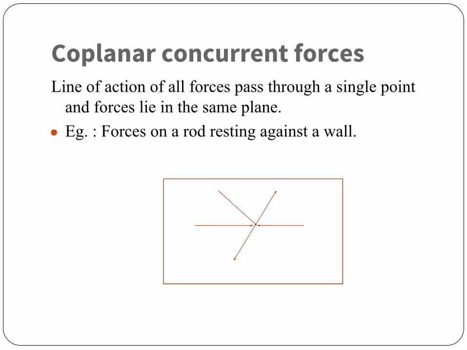
Coplanar concurrent forcesLine of action of all forces pass through a single point
and forces lie in the same plane. ● Eg. : Forces on a rod resting against a wall.
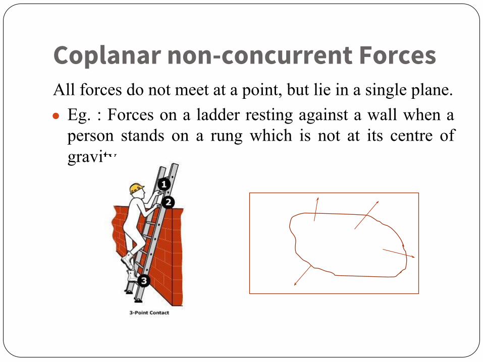
Coplanar non-concurrent ForcesAll forces do not meet at a point, but lie in a single plane.● Eg. : Forces on a ladder resting against a wall when a
person stands on a rung which is not at its centre of gravity

Non-coplanar parallel ForcesAll the forces are parallel to each other, but not in same
plane. ● Eg. : The weight of benches in a classroom.

Non-coplanar concurrent Forces
All forces do not lie in the same plane, but their lines of action pass through a single point.
● Eg. : A tripod carrying a camera

Non-coplanar non-concurrent forces
All forces do not lie in the same plane and their lines of action do not pass through a single point.
● Eg. : Forces acting on a moving bus.

Resultant Force • If a number of forces acting on a particle
simultaneously are replaced by a single force, which could produce the same effect as produced by the given forces.
These are the equivalent forces of all the given forces.
ba
1 N
2 N 3 N
F1 F2 F3
Resultant Force6 N
a b
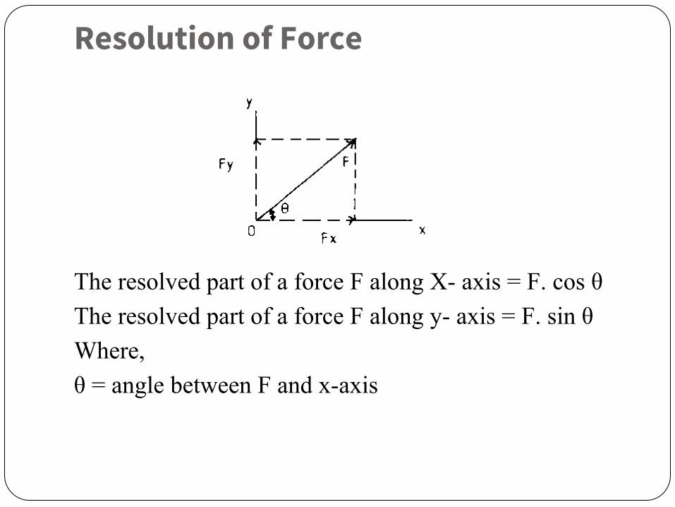
Resolution of Force
The resolved part of a force F along X- axis = F. cos θThe resolved part of a force F along y- axis = F. sin θWhere,θ = angle between F and x-axis
Laws of Mechanics
The following are the fundamental laws of mechanics:
● Newton’s first law● Newton’s second law● Newton’s third law● Newton’s law of gravitation● Law of transmissibility of forces, and● Parallelogram law of forces.
Newton’s First Law
● It states that every body continues in its state of rest or of uniform motion in a straight line unless it is compelled by external agency acting on it.
● This leads to the definition of force as the external agency which changes or tends to change the state of rest or uniform linear motion of the body.

Newton’s Second Law
● It states that the rate of change of momentum of a body is directly proportional to the impressed force and it takes place in the direction of the force acting on it.

Newton’s Third Law
● It states that for every action there is an equal and opposite reaction.
● Consider the two bodies in contact with each other. Let one body applies a force F on another. According to this law the second body develops a reactive force R which is equal in magnitude to force F and acts in the line same as F but in the opposite direction. Figure shows the action of the ball and the reaction from the floor.
Floor
BallRF
R – ReactionF - Force
Newton’s Law of Gravitation
● Everybody attracts the other body. ● The force of attraction between any two bodies is
directly proportional to their masses and inversely proportional to the square of the distance between them
Law of Transmissibility of Force
● According to this law the state of rest or motion of the rigid body is unaltered if a force acting on the body is replaced by another force of the same magnitude and direction but acting anywhere on the body along the line of action of the replaced force.
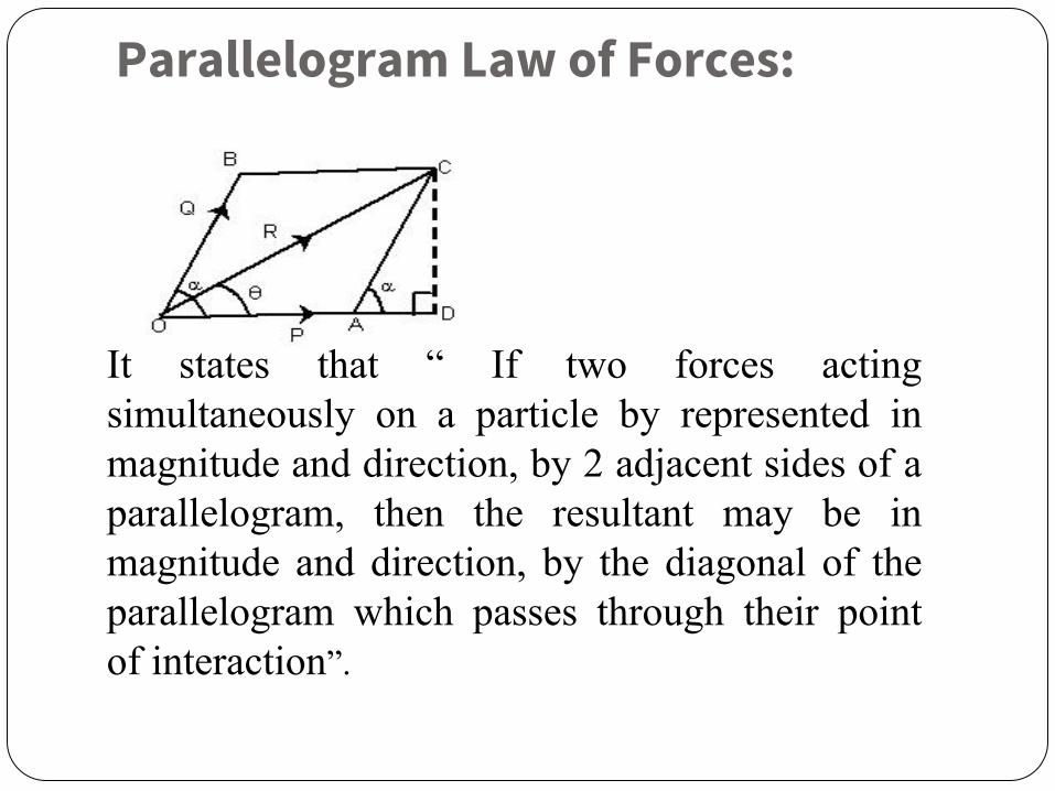
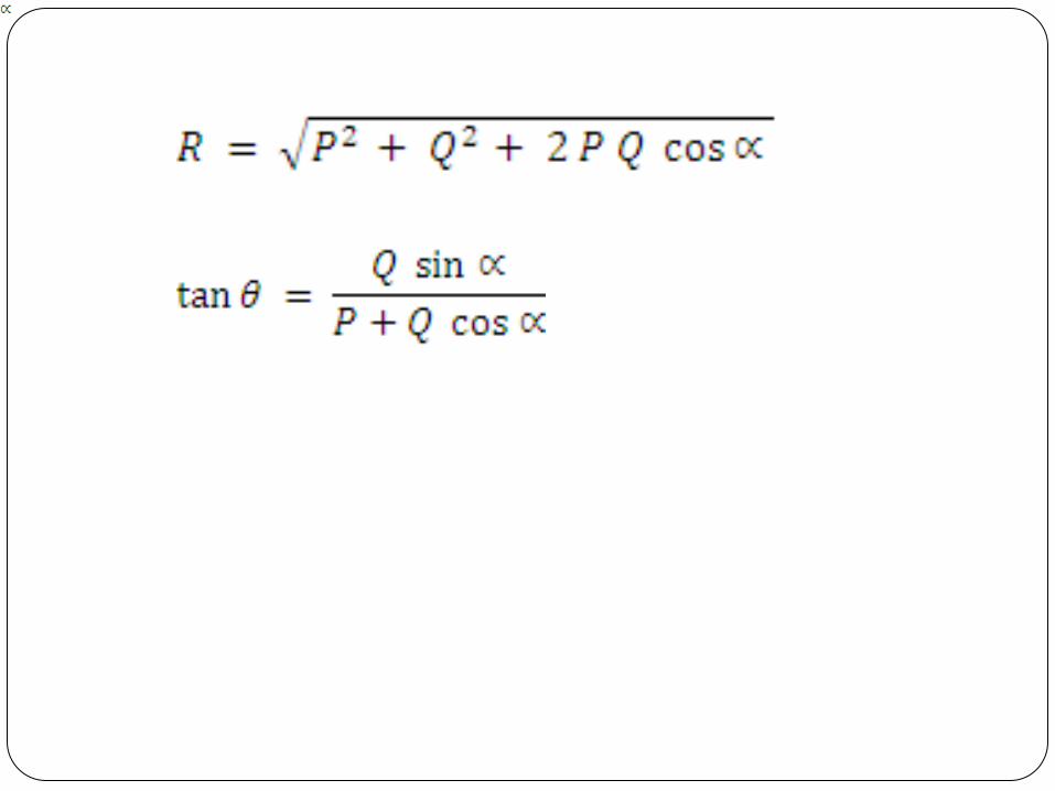
Parallelogram Law of Forces:
It states that “ If two forces acting simultaneously on a particle by represented in magnitude and direction, by 2 adjacent sides of a parallelogram, then the resultant may be in magnitude and direction, by the diagonal of the parallelogram which passes through their point of interaction”.

Triangle Law of Forces:
It states that “ if 2 forces acting simultaneously on a
particle be represented in magnitude and direction by 2 sides of a
triangle taken in order, their resultant may be represented in magnitude and direction, by the third side of the triangle taken in opposite order”.
F2
F1
R
θ
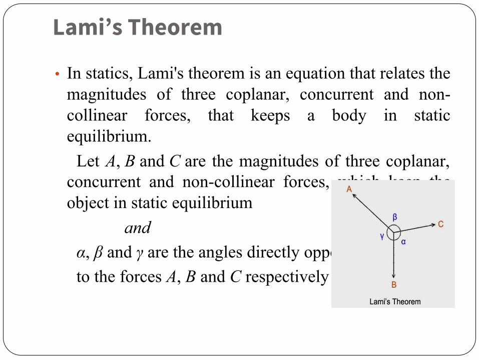
Lami’s Theorem
• In statics, Lami's theorem is an equation that relates the magnitudes of three coplanar, concurrent and non-collinear forces, that keeps a body in static equilibrium.
Let A, B and C are the magnitudes of three coplanar, concurrent and non-collinear forces, which keep the object in static equilibrium
andα, β and γ are the angles directly opposite to the forces A, B and C respectively
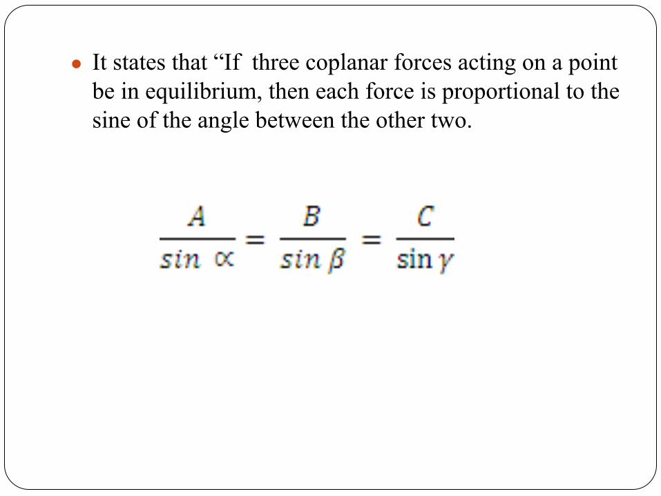
● It states that “If three coplanar forces acting on a point be in equilibrium, then each force is proportional to the sine of the angle between the other two.
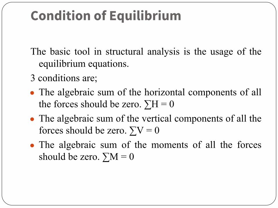
Condition of Equilibrium
The basic tool in structural analysis is the usage of the equilibrium equations.
3 conditions are;● The algebraic sum of the horizontal components of all
the forces should be zero. ∑H = 0● The algebraic sum of the vertical components of all the
forces should be zero. ∑V = 0● The algebraic sum of the moments of all the forces
should be zero. ∑M = 0
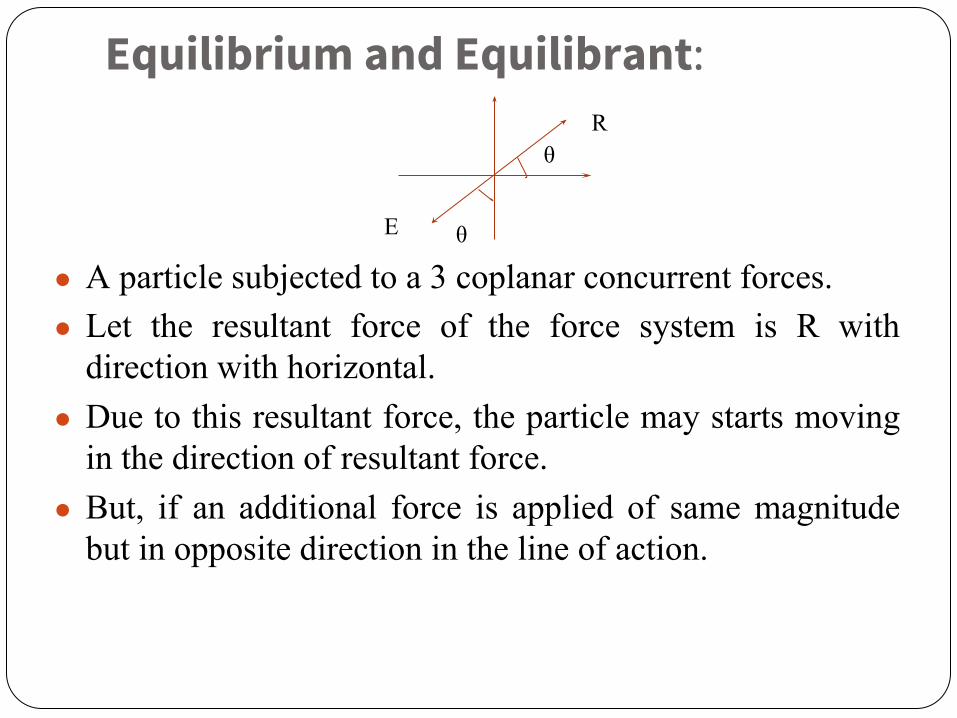
Equilibrium and Equilibrant:
● A particle subjected to a 3 coplanar concurrent forces.● Let the resultant force of the force system is R with
direction with horizontal.● Due to this resultant force, the particle may starts moving
in the direction of resultant force.● But, if an additional force is applied of same magnitude
but in opposite direction in the line of action.
R
E
θ
θ
● Then, the movement of the particle will be arrested or the particle is said to be in equilibrium.
● The force E which bring the particle to equilibrium is known as Equilibrant.
● Principle of Equilibrium developed from the force law of Equilibrium,
F = 0

Types of Structural Members
Structure:Structure refers to a system of connected parts used to
support load, such as buildings, bridges, towers, etc.Types of structural members:● Tension members● Compression members or columns● Flexural members● Members subjected to combined loading

Tension members:
● Tension members are structural elements that are subjected to axial tensile forces.
Eg: Bracing for buildings and bridges, truss members, and cables .

Tension members

Compression members
● Compression members are structural elements that are pushed together or carry a load subjected only to axial compressive forces.
Eg: Column, top chords of trusses, diagonal, bracing members ,etc.

Flexural members( Beams)
● Horizontal or inclined structural member spanning a distance between one or more supports, and carrying vertical loads across its longitudinal axis. When the cross section of the beam varies along the length it is called as tapered or haunched beam. It is designed to resist bending moment and shear force.

Types of beam
● Simply supported beam● Fixed beam● Cantilever beam● Continuous beam● Overhanging beam

● Simply supported:Beam which is supported at both the ends alone is
referred to as simply supported beam.
● Fixed beam:Beam which is held rigid at both the ends is called
fixed beam.
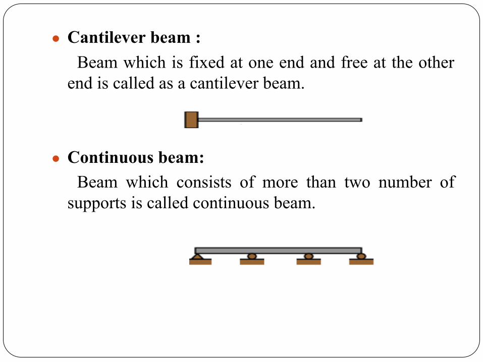
● Cantilever beam :Beam which is fixed at one end and free at the other
end is called as a cantilever beam.
● Continuous beam:Beam which consists of more than two number of
supports is called continuous beam.

● Overhanging beam:If the span of the beam is extending beyond the
supports, it is referred to as overhanging beam. The extended part beyond the support is called overhang.
There are two types of overhanging beam. ●Single side overhanging beam●Double side overhanging beam

➢ If the span of beam is extended only on one side, it is called as single side overhanging beam.
➢ If the span is extended on both the sides of support, it is called double side overhanging beam.
➢ Members subjected to combined loading:Columns subjected to flexural forces in addition to
axial forces are called as beam –columns.
Types of Load
● Dead load:Dead loads are permanent or stationary loads which
are transferred to structure throughout the life span. Dead load is primarily due to self weight of structural members.
● Live load or Imposed load :Live loads moving loads It is due to the occupancy of
the building like weights of movable partitions or furniture etc. The floor slabs have to be designed to carry either uniformly distributed loads or concentrated loads whichever produce greater stresses in the part under consideration.
Types of Load● Impact loads:
Sudden application of load is called impact. Impact load is caused by vibration or impact or acceleration.
● Wind loads:Wind load is horizontal load caused by the
movement of air relative to earth. Wind load is required to be considered in design especially when the open area of the building exceeds two times the dimensions transverse to the exposed wind surface.
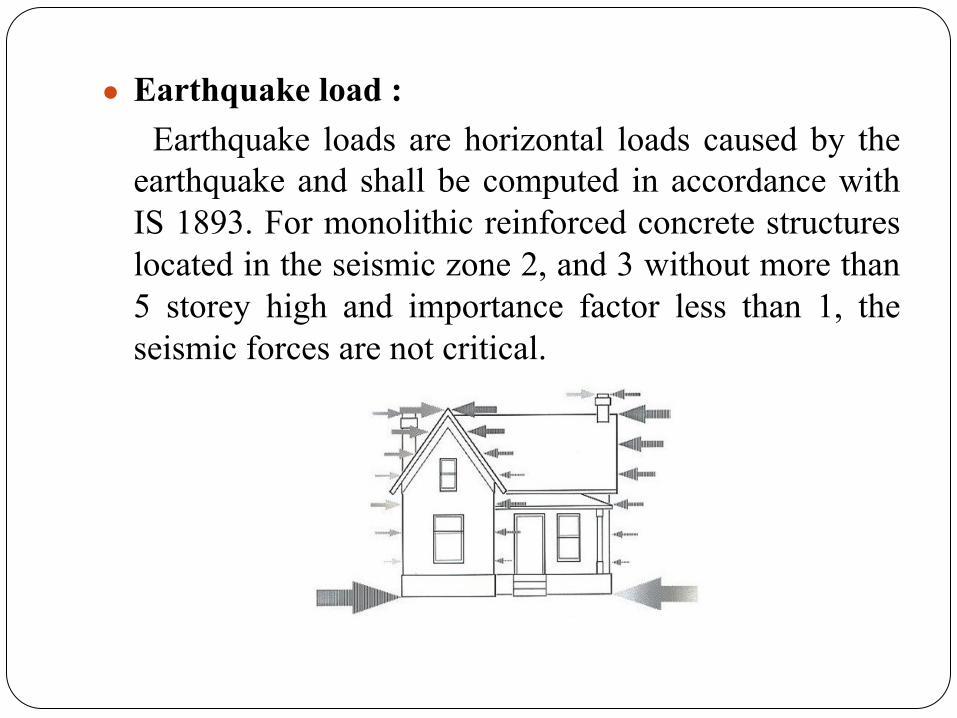
● Earthquake load :Earthquake loads are horizontal loads caused by the
earthquake and shall be computed in accordance with IS 1893. For monolithic reinforced concrete structures located in the seismic zone 2, and 3 without more than 5 storey high and importance factor less than 1, the seismic forces are not critical.
Types of Support
● The types of support used in structural members ➢ Roller ➢ Pinned ➢ Simply supported ➢ Fixed
● These supports can be located anywhere along a structural element. They are found at the ends, at midpoints, or at any other intermediate points. The type of support connection determines the type of load that the support can resist. The support type also has a great effect on the load bearing capacity of each element.
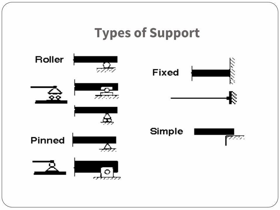
Types of Support
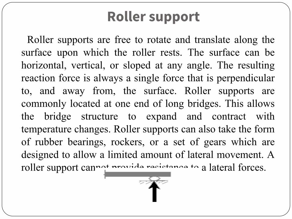
Roller supportRoller supports are free to rotate and translate along the
surface upon which the roller rests. The surface can be horizontal, vertical, or sloped at any angle. The resulting reaction force is always a single force that is perpendicular to, and away from, the surface. Roller supports are commonly located at one end of long bridges. This allows the bridge structure to expand and contract with temperature changes. Roller supports can also take the form of rubber bearings, rockers, or a set of gears which are designed to allow a limited amount of lateral movement. A roller support cannot provide resistance to a lateral forces.
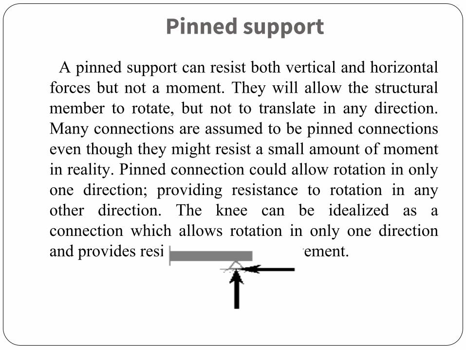
Pinned support
A pinned support can resist both vertical and horizontal forces but not a moment. They will allow the structural member to rotate, but not to translate in any direction. Many connections are assumed to be pinned connections even though they might resist a small amount of moment in reality. Pinned connection could allow rotation in only one direction; providing resistance to rotation in any other direction. The knee can be idealized as a connection which allows rotation in only one direction and provides resistance to lateral movement.
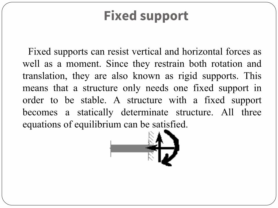
Fixed support
Fixed supports can resist vertical and horizontal forces as well as a moment. Since they restrain both rotation and translation, they are also known as rigid supports. This means that a structure only needs one fixed support in order to be stable. A structure with a fixed support becomes a statically determinate structure. All three equations of equilibrium can be satisfied.

Simple support
It is almost similar to pinned support. Simple supports are idealized by some to be frictionless surface supports. A simple support can be found as a type of support for long bridges or roof span. Simple supports are often found in zones of frequent seismic activity.

Concept of Transfer of Forces
BEAMS➢ It is a horizontal structural member which is transverse
to its axis.➢ Simplest structural element used to support loads➢ It may be curved or straight.➢ Internal stresses that develop in a beam are axial
forces, bending moment and shear force.
Transfer of loads in beams:
➢ In a beam, loads are assumed to act on a beam in a
plane containing the axis of symmetry.
➢ It carry the loads by deflecting in the same plane
without twisting.
➢ It transfers the load by bending action.
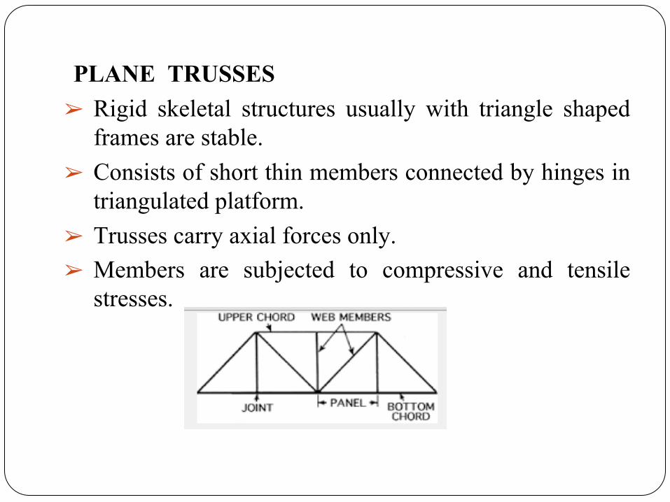
PLANE TRUSSES➢ Rigid skeletal structures usually with triangle shaped
frames are stable.➢ Consists of short thin members connected by hinges in
triangulated platform.➢ Trusses carry axial forces only.➢ Members are subjected to compressive and tensile
stresses.
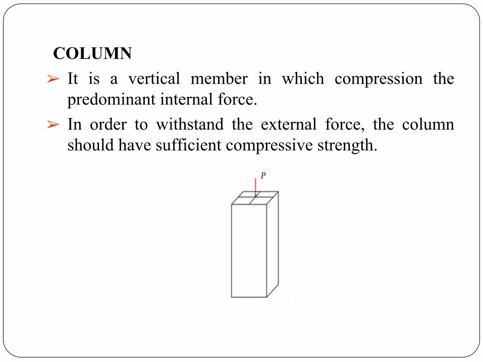
COLUMN➢ It is a vertical member in which compression the
predominant internal force.➢ In order to withstand the external force, the column
should have sufficient compressive strength.