unit a: basic principles of plant science · 2019-10-24 · 1 unit e: basic principles of soil...
TRANSCRIPT

1
Unit E: Basic Principles of Soil Science Lesson 5: Explaining a Soil Profile
Student Learning Objectives: Instruction in this lesson should result in students achieving the following objectives:
1. Explain the soil profile. 2. Explain how soils within the profile change over time. 3. Distinguish between the major horizons of a soil profile.
Recommended Teaching Time: 2 hours Recommended Resources: The following resources may be useful in teaching this lesson:
• A PowerPoint has also been developed for use with this lesson plan
List of Equipment, Tools, Supplies, and Facilities: Writing surface PowerPoint Projector PowerPoint Slides Transparency Master Soil monolith
Terms: The following terms are presented in this lesson (shown in bold italics and on PowerPoint Slide 2):
• Additions • Eluviation • Illuviation • Losses • Soil profile • Solum
• Subsoil • Substratum • Topsoil • Transformations • Translocations
Interest Approach: Use an interest approach that will prepare the students for the lesson. Teachers often develop approaches for their unique class and student situations. A possible approach is included here. Ask students what they would expect to see in a soil profile. If possible take students to a soil pit. Ask the students if they notice any color differences. Where do they see these? Does the entire section look the same? How do various sections appear to be different? Would you find certain living organisms in some sections of the profile but not in other sections?

2
Summary of Content and Teaching Strategies Objective 1: Explain the soil profile. (PowerPoint Slide 3) I. A soil profile is a vertical cross-section of the soil. When exposed, various
layers of soil should be apparent. (PowerPoint Slide 4)
A. Each layer of soil may be different from the rest in a physical or chemical way. The differences are developed from the interaction of such soil-forming factors as:
1. Parent material 2. Slope 3. Native vegetation 4. Weathering (time) 5. Climate
(PowerPoint Slide 5) B. A soil profile is usually studied to a depth of .9 to 1.5 meters.
**Use TM: E5-1 or PowerPoint Slide 6 to show the primary layers of a soil profile. Help students to see that there are differences in the soil throughout the profile. It would also be helpful to have a soil pit where students can see firsthand the various layers of a profile. Objective 2: Explain how soils within the profile change over time. (PowerPoint Slide 7) II. Soils change over time in response to their environment. The environment is
influenced by the soil-forming factors. (PowerPoint Slide 8)
A. The causes of these changes can be classified into 4 processes: 1. Additions. Materials such as fallen leaves, wind-blown dust, or
chemicals from air pollution that may be added to the soil. 2. Losses. Materials may be lost from the soil as a result of deep
leaching or erosion from the surface. (PowerPoint Slide 9)
3. Translocations. Materials may be moved within the soil. This can occur with deeper leaching into the soil or upward movement caused by evaporating water.
(PowerPoint Slide 10) 4. Transformations. Materials may be altered in the soil. Examples
include organic matter decay, weathering of minerals to smaller particles, or chemical reactions.
(PowerPoint Slide 11)
3
B. Each of these processes occurs differently at various depths. As a soil ages, horizontal layers develop and changes result.
**Use PowerPoint Slide 12 to discuss the processes of change in a soil profile. Give students the names of processes and ask for their ideas of soil profile changes for that process. Use notes above to enhance class discussion. Objective 3: Distinguish between the major horizons of a soil profile. (PowerPoint Slide 13) III. There are 3 primary soil horizons called master horizons. They are A, B, and C. These are part of a system for naming soil horizons in which each layer is identified by a code: O, A, E, B, C, and R. They will be discussed as follows: (PowerPoint Slide 14)
A. “O” horizon. This is an organic layer made up of partially decayed plant and animal debris. It generally occurs in undisturbed soil such as in a forest.
(PowerPoint Slide 15) B. “A” horizon. This is often referred to as topsoil and is the surface layer
where organic matter accumulates. Over time, this layer loses clay, iron, and other materials due to leaching. This is called eluviation. The A horizon provides the best environment for the growth of plant roots, microorganisms, and other life.
(PowerPoint Slide 16) C. “E” horizon. This is the zone of greatest eluviation. Because the clay,
chemicals, and organic matter are very leached, the color of the E horizon is very light. It usually occurs in sandy forest soils with high amounts of rainfall.
(PowerPoint Slide 17) D. “B” horizon. This horizon is referred to as the subsoil. It is often called the
“zone of accumulation” since chemicals leached from the A and E horizons accumulate here.
(PowerPoint Slide 18) This accumulation is called illuviation. The B horizon will have less
organic matter and more clay than the A horizon. Together, the A, E, and B horizons are known as the solum. This is where most of the plant roots grow.
(PowerPoint Slide 19) E. “C” horizon. This horizon is referred to as the substratum. It lacks the
properties of the A and B horizons since it is influenced less by the soil forming processes. It is usually the parent material of the soil.
(PowerPoint Slide 20) F. “R” horizon. This is the underlying bedrock, such as limestone, sandstone,
or granite. It is found beneath the C horizon.

4
**Models of soils help us to observe soil properties and explain how soil was formed. They are also valuable teaching tools when it is difficult to look at soils in the field. Soil monoliths are a kind of soil model that professional soil scientists use. A soil monolith is a vertical section that is removed from a soil profile in the field that is prepared for mounting. If you have access to a soil monolith, it and the notes above would be helpful in showing students the various layers of a soil profile. Having a soil model in your classroom might be a fun and informative way to learn about the soil in your area. There are many ways to create a model, ranging from the way professional soil scientists make them, to some simple methods to bring soil profiles into the class. Here are some options:
o Professional Method: Make a soil monolith. o Easy Method: Put soil into a tube or a jar, and layer the
horizons as they are extracted from the ground. o Easy Method: Use the one meter long Hydrology turbidity
tubes to fill with soil horizons, to get a full scale profile. o Easiest Method: Draw a soil profile and color in the different
horizons (perhaps using large pieces of paper glued to cardboard)
If you choose to create a professional monolith use LS: E5-1. This is a time consuming lab, but you will be able to keep the monoliths for many years. PowerPoint Slide 21 will show the students a picture of a soil monolith as a finished product. PowerPoint 22 will review the soil horizons. Also refer back to TM: E5-1 or PowerPoint Slide 23 to enhance discussion of soil horizons.
Review/Summary: Use the student learning objectives to summarize the lesson. Have students explain the content associated with each objective. Student responses can be used in determining which objectives need to be reviewed or taught from a different angle. Questions on PowerPoint Slide 24 can also be used. Application: Students will be able to take the information learned an apply it in their lives. Evaluation: Evaluation should focus on student achievement of the objectives for the lesson. Various techniques can be used, such as student performance on the application activities. A sample written test is attached.

5
Answers to Sample Test: Part One: Matching 1=d, 2=c, 3=a, 4=b, 5=e, 6=f Part Two: Completion 1. transformation 2. topsoil 3. organic 4. R 5. A Part Three: Short Answer 1. Use TM: E5-1 as a guide for scoring this sketch. 2. Materials in the soil may be lost as a result of leaching or erosion. 3. A Horizon—darker, contains microorganisms and will be relatively uniform in texture (probably medium or moderately fine). C Horizon—lighter in color, contains parent material, which may be sandy and gravelly.
6
Sample Test Name_____________________________________
Test
Unit E Lesson 5: Explaining a Soil Profile
Part One: Matching Instructions. Match the term with the correct response. Write the letter of the term by the definition.
a. soil profile c. substratum e. illuviation b. translocation d. solum f. subsoil
_______ 1. Area where most plant roots grow. _______ 2. C horizon. Usually composed of the parent material of the soil and
has had little soil forming activity. _______ 3. A vertical cross-section of the soil. _______ 4. Process of materials moving within the soil horizons. _______ 5. The accumulation of chemicals, clay, iron, and other materials in the
B horizon. _______ 6. Often referred to the B horizon. Part Two: Completion Instructions. Complete the following statements. 1. As materials such as organic matter and minerals are altered in the soil, this
process is called ____________________________. 2. The A horizon is often referred to as ___________________________. 3. The O horizon is often composed of an _________________ layer made up of
decayed plant and animal debris. 4. The ____________ horizon is underlying bedrock, such as limestone,
sandstone, or granite found underneath the C horizon. 5. The _____________ horizon is the one best suited for growth of plant roots.

7
Part Three: Short Answer Instructions. Use the space provided to answer the following questions. 1. Draw a soil profile and label each of the three major horizons. 2. Explain how “losses” might occur that will cause a change in the soil profile. 3. Explain how the A horizon is different from the C horizon in terms of color and content.

8
TM: E5-1
PRIMARY LAYERS OF A SOIL PROFILE

9
LS: E5-1 Name_____________________________________
Lab Sheet
Creating a Soil Monolith
If you have a large class, break them up into groups and make multiple soil monoliths so that each student can be involved in the process.
Have the students choose a section of the exposure and smooth out a vertical face in preparation for extraction. Keep in mind that this is the face that will eventually be displayed on the monolith. Follow the steps below to create a professional monolith.
1.) Excavate pit ( 4 feet deep) - a minimum of about 12 inches additional working space is required on each side of the profile extraction area. Moist soils are nearly essential. Smooth exposed profile face ( this is the face you will eventually pick for your finished profile).

10
2.) Place a 2 foot angle-iron frame (with inside dimensions of 4" x 2" x 40") against exposed profile.
3.) Insert the cutting edge into the profile-face to mark the edges of the frame (hammer or other pressure).

11
4.) Remove frame and carve the profile to be captured from the pit face by removing soil from the area to the outside of the marked profile.
5.) Remove soil to a depth of at least 2" so that the frame fits perfectly over the sculptured profile.

12
6.) Attach a flat board (approximately 3/4" x 8" x 48") over the flat side of welded angle iron frame with C-clamps.

13
7.) Depress the frame over the sculptured profile being careful to allow no side- to-side or vertical slippage and maintain constant pressure until profile is free from the pit face.
8.) Excavate along both sides and the bottom of the frame with the objective of capturing 2-6 inches more profile than is eventually required to fill the frame.

14
9.) When both sides are essentially mined to the center, insert a tiling spade at the surface about 4-6 inches beyond the frame and complete the separation of the profile from the pit face. Care must be exercised to insure the sculptured profile does not slip downward or is otherwise pulled from the frame.

15
This is a very precarious step. The frame containing the separated profile is simply tilted away from the face in one smooth motion.
10.) Then it is lifted from the pit. Place the frame, board-side down, on a flat surface. Gently yet firmly depress the extruding profile downward into the frame and against the backing board.

16
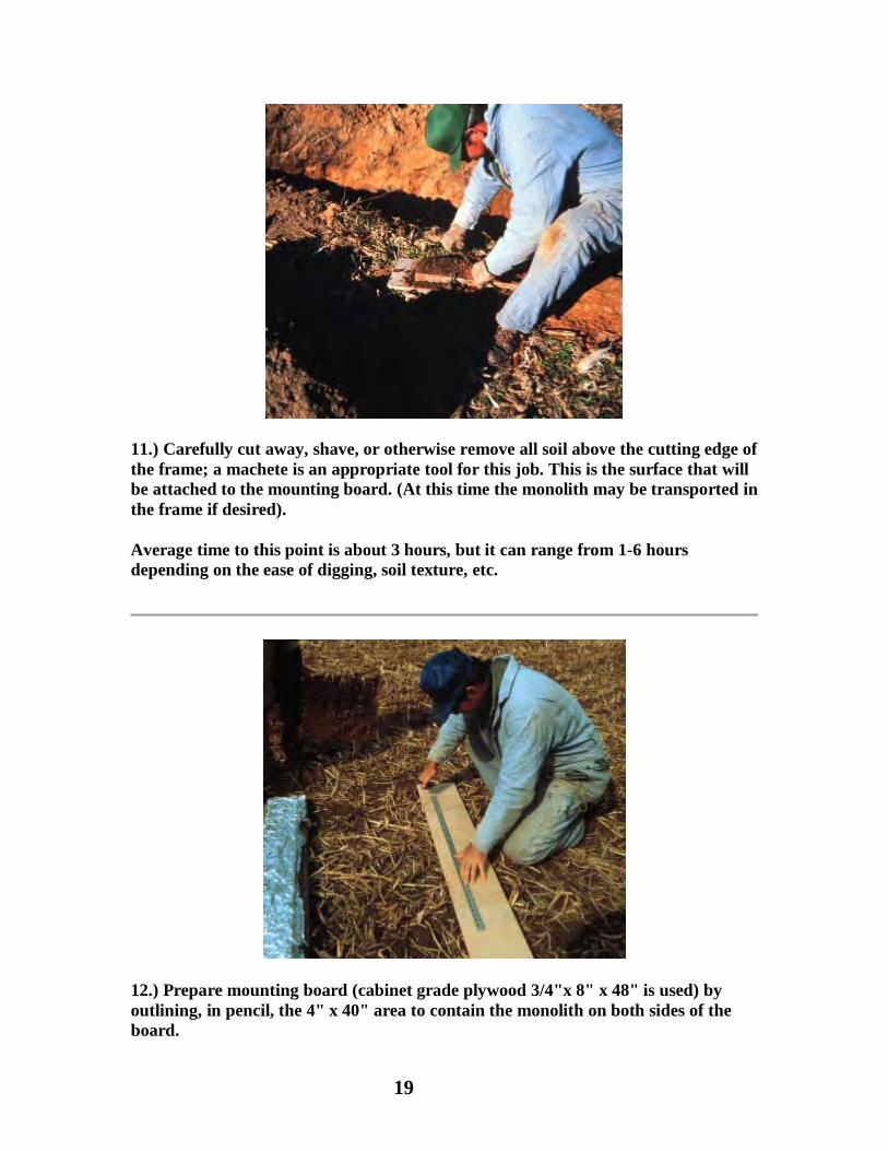
11.) Carefully cut away, shave, or otherwise remove all soil above the cutting edge of the frame; a machete is an appropriate tool for this job. This is the surface that will be attached to the mounting board. (At this time the monolith may be transported in the frame if desired).
Average time to this point is about 3 hours, but it can range from 1-6 hours depending on the ease of digging, soil texture, etc.
12.) Prepare mounting board (cabinet grade plywood 3/4"x 8" x 48" is used) by outlining, in pencil, the 4" x 40" area to contain the monolith on both sides of the board.
17
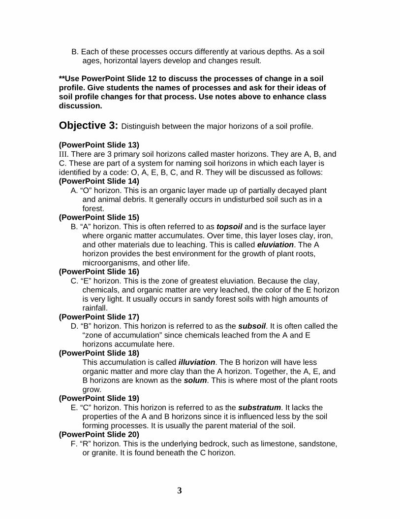
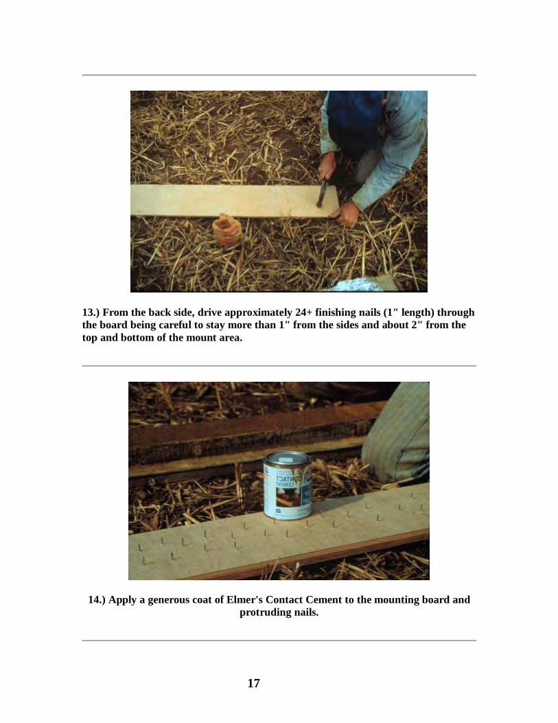
13.) From the back side, drive approximately 24+ finishing nails (1" length) through the board being careful to stay more than 1" from the sides and about 2" from the top and bottom of the mount area.
14.) Apply a generous coat of Elmer's Contact Cement to the mounting board and protruding nails.

18
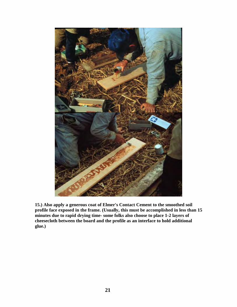
15.) Also apply a generous coat of Elmer's Contact Cement to the smoothed soil profile face exposed in the frame. (Usually, this must be accomplished in less than 15 minutes due to rapid drying time- some folks also choose to place 1-2 layers of cheesecloth between the board and the profile as an interface to hold additional glue.)
19
11.) Carefully cut away, shave, or otherwise remove all soil above the cutting edge of the frame; a machete is an appropriate tool for this job. This is the surface that will be attached to the mounting board. (At this time the monolith may be transported in the frame if desired).
Average time to this point is about 3 hours, but it can range from 1-6 hours depending on the ease of digging, soil texture, etc.
12.) Prepare mounting board (cabinet grade plywood 3/4"x 8" x 48" is used) by outlining, in pencil, the 4" x 40" area to contain the monolith on both sides of the board.

20
13.) From the back side, drive approximately 24+ finishing nails (1" length) through the board being careful to stay more than 1" from the sides and about 2" from the top and bottom of the mount area.
14.) Apply a generous coat of Elmer's Contact Cement to the mounting board and protruding nails.
21
15.) Also apply a generous coat of Elmer's Contact Cement to the smoothed soil profile face exposed in the frame. (Usually, this must be accomplished in less than 15 minutes due to rapid drying time- some folks also choose to place 1-2 layers of cheesecloth between the board and the profile as an interface to hold additional glue.)

22
16.) Align mounting board with soil profile and depress board with protruding nails into the profile with firm even pressure. Take steps to insure board is squarely aligned with profile before applying firm pressure.

23
17.) Immediately invert frame and mounting board combination so that mounting board is now on the bottom. (Usually this step requires a coordinated effort between two people).

24
18.) Remove C-Clamps and temporary backing board from the frame.

25
19.) Place a piece of board (cut to pass through the metal frame) on the soil profile exposed inside the frame.
20.) Press down on the board and pull up on the frame, simultaneously, to remove the frame from the soil profile.

26
21.) As the frame is raised about 3/4", quarter-round molding can be placed (tacked lightly) along both sides and ends to hold profile intact until glue has dried. This step may or may not be needed depending on texture, soil moisture content, and disposition of the monolith. Ideally, if molding is used, it should be loosened before glue completely hardens although it can be removed later or allowed to remain.
(Monoliths can be transported at this time if care is exercised in keeping them flat and relatively free from drastic bumps).

27
22.) Ideally, the exposed profile is picked or dressed to show desired structure or finish before the soil dries; however, it can be remoistened for this process. (Dentists' picks, walnut picks, or other fine tools are used for this process . Avoid tool smear marks on finished surface - they will be very obvious on the finished monolith).
Pick the profile, allowing about 1-1 1/2 inches of soil to remain. Remove all loose soil particles from the dressing process with low air pressure.

28
23.) Allow soil monolith to air dry for 2-3 weeks - it is absolutely essential that all moisture be removed from the monolith before applying "hardening compound", otherwise very undesirable and almost irreversible chemical reactions occur.
HARDENING COMPOUND PREPARATION AND FINAL SOIL MONOLITH PROCEDURES
1. Prepare hardening compound at least 24 hours in advance of pouring the monolith (consists of mixing 1 pint acetone- high strength- with 37 grams vinyl chloride/vinyl acetate resin {Union Carbide, Corp.}. This VC powder should dissolve completely - it may take 2-3 days to dissolve.
2. In a well-ventilated area, pour the hardening compound over the soil, completely saturating the surface, and taking care not to "pond" more liquid in structural cavaties than can readily be absorbed. Due to textural differences and absorption rates, the amount to pour and elapsed time between pours varies considerably.
3. The objective is to completely saturate the soil profile. Usually on fine-loamy soils, pour 2-3 times and use about 1-1 1/2 quarts of hardening compound per monolith. On some occasions, a second pour is done within one hour of the initial, followed by a third pour 24 hours later.
4. Allow profile to dry for about one week. Remove excess glue, which usually requires sanding.
5. Paint or finish mounting board as desired and apply soil name plaque and/or lettering, horizonation, depth, etc. (A flat, black background is best for emphasizing the soil profile).
Note: While there may be simpler, easier methods of extracting soil profiles and procedures requiring less time for preparing soil monoliths than this process, this process results in a better end product. Total time is estimated at 20-40 hours per each monolith.