unit 63: industrial services unit workbook 3
TRANSCRIPT

Unit Workbook 3 - Level 5 ENG – U63 Industrial Services © 2020 UniCourse Ltd. All Rights Reserved
Page 1 of 19
Pearson BTEC Level 5 Higher Nationals in Engineering (RQF)
Unit 63: Industrial Services
Unit Workbook 3 in a series of 4 for this unit
Learning Outcome 3
Steam
SAMPLE
Unit Workbook 3 - Level 5 ENG – U63 Industrial Services © 2020 UniCourse Ltd. All Rights Reserved
Page 2 of 19
Contents INTRODUCTION .................................................................................................................................................. 3
GUIDANCE .......................................................................................................................................................... 4
1.1 Steam Power Plant .................................................................................................................................. 5
1.1.1 Tables and Charts ............................................................................................................................. 5
1.1.2 Steam Plant Circuit Diagrams .......................................................................................................... 7
1.1.3 Steam & Energies ............................................................................................................................. 8
1.1.4 Power Steam Efficiencies ............................................................................................................... 10
1.1.5 Process Steam Efficiencies ............................................................................................................. 17
SAMPLE

Unit Workbook 3 - Level 5 ENG – U63 Industrial Services © 2020 UniCourse Ltd. All Rights Reserved
Page 3 of 19
INTRODUCTION Discuss the provision of steam services for process and power use.
• Steam Power Plant: o Use of tables and charts to analyse wet and dry saturated steam. o Circuit diagrams showing steam raising plant. o Process steam: enthalpy of evaporation, available energy. o Overall plant efficiencies for process. o Power steam: superheated steam, turbine efficiency, Rankine cycle, cooling towers. o Overall plant efficiency for power. o Efficiencies and improvements.
SAMPLE

Unit Workbook 3 - Level 5 ENG – U63 Industrial Services © 2020 UniCourse Ltd. All Rights Reserved
Page 4 of 19
Purpose
Theory
Question
Challenge
ee
Example
Video
GUIDANCE This document is prepared to break the unit material down into bite size chunks. You will see the learning
outcomes above treated in their own sections. Therein you will encounter the following structures;
Explains why you need to study the current section of material. Quite often learners
are put off by material which does not initially seem to be relevant to a topic or
profession. Once you understand the importance of new learning or theory you will
embrace the concepts more readily.
Conveys new material to you in a straightforward fashion. To support the treatments
in this section you are strongly advised to follow the given hyperlinks, which may be
useful documents or applications on the web.
The examples/worked examples are presented in a knowledge-building order. Make
sure you follow them all through. If you are feeling confident then you might like to
treat an example as a question, in which case cover it up and have a go yourself. Many
of the examples given resemble assignment questions which will come your way, so
follow them through diligently.
Questions should not be avoided if you are determined to learn. Please do take the
time to tackle each of the given questions, in the order in which they are presented.
The order is important, as further knowledge and confidence is built upon previous
knowledge and confidence. As an Online Learner it is important that the answers to
questions are immediately available to you. Contact your Unit Tutor if you need help.
You can really cement your new knowledge by undertaking the challenges. A challenge
could be to download software and perform an exercise. An alternative challenge
might involve a practical activity or other form of research.
Videos on the web can be very useful supplements to your distance learning efforts.
Wherever an online video(s) will help you then it will be hyperlinked at the appropriate
point.
SAMPLE

Unit Workbook 3 - Level 5 ENG – U63 Industrial Services © 2020 UniCourse Ltd. All Rights Reserved
Page 8 of 19
In a steam power plant, there are three basic types of components: turbines, pumps and heat exchangers
and with these different components comes a different characteristic change in the working properties of
the fluid. It is important to understand that the purpose of a turbine is to extract energy from the steam and
use that to do work, in most cases by rotating a shaft, leading to this work being converted to electrical
energy via the generator.
The work done by a turbine, under steady flow conditions, is actually equivalent to the decrease in enthalpy
of the steam and can be expressed in the following way:
𝑊𝑇𝑢𝑟𝑏𝑖𝑛𝑒 = 𝑀𝑎𝑠𝑠 𝐹𝑙𝑜𝑤 𝑅𝑎𝑡𝑒(𝐻𝐼𝑛 − 𝐻𝑂𝑢𝑡)
The purpose of a pump is to move the steam by doing work upon it, in this case the work done of the pump
is equivalent to the increase in enthalpy of the steam. As with the turbine, a pump is not 100% efficient. The
key difference between this and a turbine, is that the turbine extracts energy from the steam whilst the
pump increases the steam’s energy.
A heat exchanger is quite simply a device which transfers heat between two working fluids, examples include
hot gases being used to evaporate feedwater and the condenser being used to transfer heat from the
working fluid to the surrounding environment.
1.1.3 Steam & Energies Enthalpy of evaporation, sometimes known as enthalpy of vaporisation, heat of evaporation or (latent) heat
of vaporisation, is a term given to the amount of energy that must be added to a substance in order to turn
it from a liquid to a gas, it is dependent on the pressure at which this transformation takes place and is
measured in J/kg. Some older units are still used in certain industries and in other countries, such as kcal/mol
or Btu/lb.
The Carnot cycle is a principle which demonstrates the maximum theoretical efficiency of a heat engine, i.e.
a thermodynamic system transferring heat and work, which is based on the temperature of heat input and
the temperature of the heat rejected, and assuming that the process as a whole is reversible. In reality this
is not the case, however a theoretical Carnot efficiency, sometimes known as ideal efficiency, can be used
to show the unattainable upper limit for a real-life system’s efficiency. Since the Carnot efficiency is
dependent on the temperature of the heat input (source) and the temperature of the heat rejected (sink), it
makes sense that to improve efficiency, one would simply increase the temperature of the heat source and
decrease the temperature of the heat sink. This idea has certain limits because the ultimate heat sink is the
Earth, whose temperature is fixed, whilst the heat source temperature is also somewhat limited based on
the fuel that is being used and the materials that the whole system is made from. Considering these
limitations, the highest possible Carnot efficiency is 73%.
Not all energy is available to be used usefully and some is rejected to the surrounding environment. Firstly,
if we can consider that the working fluid is water/steam then this immediately causes efficiency restrictions,
heat is added to this fluid at constant pressure and at below the maximum allowable material temperature,
which means that not all of the available energy is harnessed. The following entropy-temperature graph
shows the amounts of energy which are available, unavailable and additionally available:
SAMPLE

Unit Workbook 3 - Level 5 ENG – U63 Industrial Services © 2020 UniCourse Ltd. All Rights Reserved
Page 9 of 19
Figure 1.4: Typical Steam Plant Cycle
The actual energy available can be seen as the area under the 1-2-3-4 curve, whilst the available energy from
an ideal Carnot cycle can be seen as the area under the 1-2-4 curve, with both operating between the exact
same temperatures. The Carnot cycle is not suitable to be used practically for a few different reasons, firstly,
it would require an enormous amount of pumping work, this pumping would also likely cause cavitation in
the system and the ideal mixture required at point 1 would also pose insurmountable technical problems. A
Carnot steam cycle on an entropy-temperature graph can be seen below:
Figure 1.5: Carnot Cycle on Temperature-Entropy Diagram
SAMPLE

Unit Workbook 3 - Level 5 ENG – U63 Industrial Services © 2020 UniCourse Ltd. All Rights Reserved
Page 13 of 19
Now we state our known conditions:
At point 1, Pressure (p) = 90 kPa and the working medium is fluid water which has come out of the condenser;
therefore, we know that we have a saturated liquid which, in turn, means that the quality or dryness ratio
(x) = 0. Now consult the steam tables or use a steam calculator to determine all of the other conditions at
this point (https://beta.spiraxsarco.com/resources-and-design-tools/steam-tables):
The key useful characteristics here are the specific volume (v), specific enthalpy (h) and specific entropy (s)
which we will subscript these with ‘1’ to signify that they apply to point 1 on the system:
𝑣1 = 1.04 × 10⁻³ 𝑚3
𝑘𝑔
ℎ1 = 404686 𝐽
𝑘𝑔
𝑠1 = 1269.77 𝐽
𝑘𝑔𝐾
Let us now consider point 2 on the system: we know that the pressure (p) is 4 MPa. From point 1 to point
two on the graph is a straight line upwards, meaning that there is no change in entropy, i.e. it is an isentropic
process. Therefore s1=s2 and the working medium is still a fluid, meaning that the specific volume is
unchanged, (v1=v2), these can both be signified simply as the specific volume of the fluid (vf). At this point
we cannot use the steam tables to determine parameters because we do not know the quality, however we
can determine the work done of the pump if we so wish, by using the formula below:
−𝑊𝑃𝑢𝑚𝑝 = 𝑣𝑓(𝑝2 − 𝑝1)
−𝑊𝑃𝑢𝑚𝑝 = 1.04 × 10⁻³(4 × 10⁶ − 90000) = 4066 𝐽
𝑘𝑔
SAMPLE

Unit Workbook 3 - Level 5 ENG – U63 Industrial Services © 2020 UniCourse Ltd. All Rights Reserved
Page 14 of 19
It transpires that this is actually an incredibly useful value to determine because, in an isentropic process the
work done is equivalent to the change in enthalpy, and so:
−𝑊 = 𝛥ℎ
In our case, we can say specifically that:
−𝑊𝑃𝑢𝑚𝑝 = ℎ2 − ℎ1
4066 = ℎ2 − 404686
ℎ2 = 408752𝐽
𝑘𝑔
At point 3, there is no change in pressure, so p3=p2=4 Mpa but rather we are now given the temperature of
380°C, where the medium has been changed from a saturated fluid to a superheated steam. We can now
use the steam tables to look up the values of its characteristics.
We can see that the values are as follows:
𝑣3 = 0.07 𝑚3
𝑘𝑔
SAMPLE
Unit Workbook 3 - Level 5 ENG – U63 Industrial Services © 2020 UniCourse Ltd. All Rights Reserved
Page 15 of 19
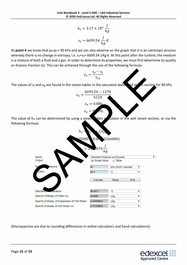
ℎ3 = 3.17 × 10⁶ 𝐽
𝑘𝑔
𝑠3 = 6699.54 𝐽
𝑘𝑔𝐾
At point 4 we know that p4=p1= 90 kPa and we can also observe on the graph that it is an isentropic process
whereby there is no change in entropy, i.e. s3=s4= 6699.54 J/kg K. At this point after the turbine, the medium
is a mixture of both a fluid and a gas. In order to determine its properties, we must first determine its quality
or dryness fraction (x). This can be achieved through the use of the following formula:
𝑥4 =𝑠4 − 𝑠𝑓
𝑠𝑓𝑔
The values of sf and sfg are found in the steam tables in the saturated water and steam section for 90 kPa.
𝑥4 =6699.54 − 1270
6124
𝑥4 = 0.886
𝑥4 = 88.6%
The value of h4 can be determined by using a steam tables calculator in the wet steam section, or via the
following formula:
ℎ4 = ℎ𝑓 + 𝑥4(ℎ𝑓𝑔)
ℎ4 = 405000 + 0.886(2266000)
ℎ4 = 2412676𝐽
𝑘𝑔
(Discrepancies are due to rounding differences in online calculators and hand calculations).
SAMPLE
Unit Workbook 3 - Level 5 ENG – U63 Industrial Services © 2020 UniCourse Ltd. All Rights Reserved
Page 16 of 19
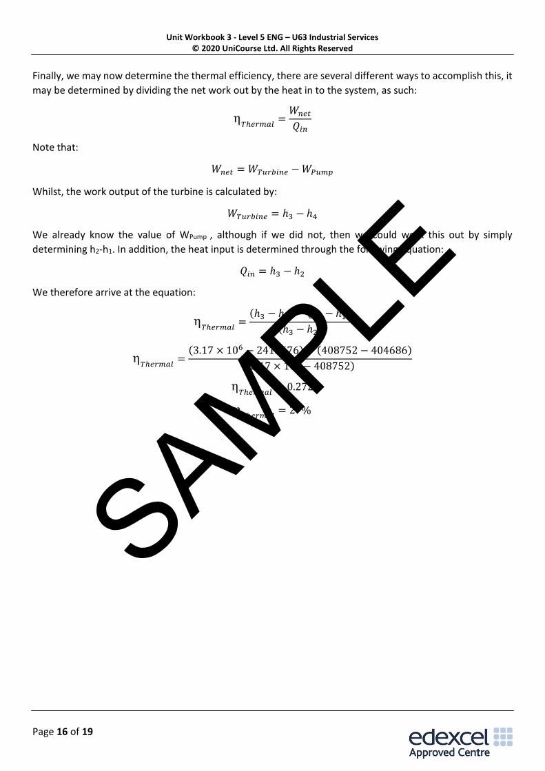
Finally, we may now determine the thermal efficiency, there are several different ways to accomplish this, it
may be determined by dividing the net work out by the heat in to the system, as such:
η𝑇ℎ𝑒𝑟𝑚𝑎𝑙
=𝑊𝑛𝑒𝑡
𝑄𝑖𝑛
Note that:
𝑊𝑛𝑒𝑡 = 𝑊𝑇𝑢𝑟𝑏𝑖𝑛𝑒 − 𝑊𝑃𝑢𝑚𝑝
Whilst, the work output of the turbine is calculated by:
𝑊𝑇𝑢𝑟𝑏𝑖𝑛𝑒 = ℎ3 − ℎ4
We already know the value of WPump , although if we did not, then we could work this out by simply
determining h2-h1. In addition, the heat input is determined through the following equation:
𝑄𝑖𝑛 = ℎ3 − ℎ2
We therefore arrive at the equation:
η𝑇ℎ𝑒𝑟𝑚𝑎𝑙
=(ℎ3 − ℎ4) − (ℎ2 − ℎ1)
(ℎ3 − ℎ2)
η𝑇ℎ𝑒𝑟𝑚𝑎𝑙
=(3.17 × 10⁶ − 2412676) − (408752 − 404686)
(3.17 × 10⁶ − 408752)
η𝑇ℎ𝑒𝑟𝑚𝑎𝑙
= 0.272
η𝑇ℎ𝑒𝑟𝑚𝑎𝑙
= 27%
SAMPLE