unit 2: internet of things - colvee
TRANSCRIPT

UNIT 2: INTERNET OF THINGS
OVERVIEW
IoT, Internet of Things is the term used to represent how “things” can be interconnected to the
Internet to communicate and automate different processes. For example, think of a fridge that
can detect the levels of products, and notify owner on the way back to home, to order them
directly from the supermarket, and owner just need to drive through to pick up products. Other
examples include, home automation, environmental monitoring, and so on.
LEARNING OUTCOMES
By the end of this unit, you should be able to do the following:
1. Identify the Components that forms part of IoT Architecture
2. Determine the most appropriate IoT Devices and Sensors based on Case Studies.
3. Setup the connections between the Devices and Sensors.
4. Evaluate the appropriate protocol for communication between IoT
5. Analyse the communication protocols for IoT
TOPIC 1: IoT ARCHITECTURES
Introduction
Among the range of new emerging technologies, Internet of Things is perhaps the one that is
going to have the greatest impact in terms of adoption, ubiquitous and pervasiveness. This
statement might seem far fetch, but the interconnection of “Things” and the Internet unlocks a
vast range of unimaginable applications, ranging from Agriculture, Environment, Gaming, up
to Zoology. To facilitate the emergence of those applications, it is necessary to have a well-
structured IoT architecture for the implementation of IoT-based solution.

Requirements for IoT Architecture
IoT Architecture a set of standards and layers that will group requirements of different devices,
actuators and protocols. In order to pave the way for fascinating IoT Applications, the IoT
Architecture needs to consist of the following:
Distributed open architecture with end to end characteristics, interoperability of
heterogeneous systems, neutral access, clear layering and resilience to physical network
disruption.
Decentralized autonomic architectures based on peering of nodes.
Architectures moving intelligence at edge of the networks, up to users’ terminals and
things.
Cloud computing technology, event-driven architectures, disconnected operations and
synchronization.
Use of market mechanisms for increased competition and participation.
Extracted from: Sundmaeker, 2010
IoT Models
To be able to come up with a well-structured IoT architecture, the first step would be to review
the existing IoT reference architectures proposed by different organisations as follows:
The Industrial Internet Consortium has delivered the Industrial Internet Reference
Architecture (IIRA), with a strong industry focus specifically on industrial IoT
applications (Shi-Wan et al., 2017).
The Internet of Things IoT-A EU initiative delivered a detailed architecture and model
from the functional and information perspectives (Carrez, 2017).
The Reference Architecture Model Industrie 4.0 (RAMI 4.0) goes beyond IoT, adding
manufacturing and logistics details. This is effectively a reference architecture for smart
factories dedicated to IoT standards that started in Germany (Platform-i40.de, 2018).
The IEEE P2413 project formed a working group dedicated to the IoT’s architectural
framework, highlighting protection, security, privacy and safety issues (Soo, 2016).

The common feature that can be derived from all the architectures mentioned above, is that
they have well-defined boundaries for different activities clustered into layers, which shows
how important aspects of the overall system operates and interacts among themselves. The
layers can be adopted by different technologies, components, brands and so on.
Conceptually, the layers can be identified as the following layers:
1. Physical devices: The “things” in the IoT
2. The gateway: A border module to link resource-limited devices
3. Integration: A protocol to allow communication between nodes and servers
4. Applications: Data processing and analytics, for example
Figure 1 – IoT Architecture (Walter, 2017)
Layer 1 – Physical Layer (Device Layer)
In this layer, devices such as sensors are used to capture parameters about the environment and
to convert those into signals. Also in this layer, actuators are being used for the process of
automation to perform any mechanical processes. Communication between the devices and
servers can happen in two ways.
1. Either each device communicate directly to the servers using protocols such as REST,
MQQT, XMPP or AMQP (explained in next topic);
2. Or they communicate indirectly through a gateway. This will allow devices to just
capture parameters and send them to the gateway through short-range communication
protocols like Zigbee, Bluetooth and RF. The gateway would then combine the received
the messages and transmit to the required server.

Layer 2 – Gateway Layer
In this layer, gathering of data from various devices is the main requirement. It performs
translation of various messages received from heterogeneous devices and sends the leverage
data using protocols mentioned above. Apart from doing the receiving and sending of data, it
can also provide services like data filtering, cleanup, aggregation and packet content inspection.
Layer 3 - Integration Layer
Most of the time this layer is hosted in the cloud; however it could also be a dedicated server.
This layer would be responsible for the collection of data from the gateways and storing in such
way that they can be queried and processed. That is why the cloud is the preferred host as they
also provided data redundancy. Examples are Apache Kafka, ThinkSpeed, Microsoft Azure
(IoT).
Layer 4 - Application Layer
Finally, the Application Layer is responsible for the presenting the data collected, processed
and labelled in such a way that it hides the complexities and is more inductive to users. In this
layer, the data can be further enriched by applying machine learning algorithms and predictions
can be made and presented to users. Presentation of final results can be through website or
mobile apps. Examples of such platforms are IBM’s Bluemix, Apache Spark, and so on.

TOPIC 2 - IoT COMMUNICATION AND PROTOCOLS
Introduction
Internet of Things encompasses a large range of applications (Agriculture, Smart Home, Smart
Town, Smart Bus, Environment Monitoring, etc) that scale from one controlled device up to
colossal amount of cross-platform distributions of different implanted technologies all
connected together and in real-time through cloud systems. Making all those different devices
talk to each other, and retrieving meaning information have led to the emergence of different
communication protocols at each layer of the communication protocol stack.
IoT Networking
The actual TCP/IP networking model has 4 layers with protocols defined at each layer.
However since IoT has its own specificity, different protocols have emerged at each layer to
suit it. They are presented in Figure 2 below.
Figure 2 – IoT and TCP/IP
Layer 1 (Link Layer) – concerns the infrastructure of the network. While current networking
infrastructure uses mainly Wired or Wireless networking, IoT infrastructure uses a variety of
technologies including:
1. WiFi – (Wireless Fidelity), latest version can cover up to 400m and can provide
bandwidth up to about 1 Gbps.
2. Bluetooth – can have a data rate up to 3 Mbps and maximum range of 100m.

3. ZigBee – works in the 2.4 GHz with a data rate of 250 Kbps and up to 200m or range.
It also supports AES encryption.
4. WiMax – can cover large area up to 50 km (fix device) and 15 km (mobile device) and
can provide a bandwidth up to 40 Mbps.
5. Cellular (2G/3G/4G) – provide worldwide coverage and varying bandwidth. However
operational costs are higher.
6. Others (less popular) include WirelessHart, DigiMesh, NFC, ANT, LoRaWAN, …
Layers 2 and 3 (Network and Transport Layer) - look at the communication protocols which
includes routing (choosing optimal path) and providing reliability (retransmission). Some
existing protocols are being used, while some new ones have also seen the day.
1. IPv6 is the upgraded version of IPv4, which could not cope with boom of ip addresses
demand. IPv6 can provide 1 IP address per cm2. It also has other features such as
encryption and simple header (less overhead).
2. 6LoWPAN is the acronym of IPv6 over Low power Wireless Personal Area Networks.
“It is an adaption layer for IPv6 over IEEE802.15.4 links. This protocol operates only
in the 2.4 GHz frequency range with 250 kbps transfer rate" (Postscapes.com, 2017).
3. UDP (User Datagram Protocol) is used an as alternative to TCP (reliable delivery), that
provides performance tuned for real-time applications. However UDP does not provide
reliability; therefore this aspect has to be addressed in higher level protocols.
4. Others include QUIC, Aeron, DTLS, NanoIP, CCN and TSMP.
Layer 4 (Application Layer) – concerns the data protocols, that is, specific for the application
it is meant for. In this layer, the predominant protocol is HTTP (HyperText Transfer Protocol),
which is still used by a lot of IoT Systems. However, some new protocols have also been
implemented.

1. HTTP – mainly designed for web browsers, it also important for IoT as it supports the
REST API which is becoming the main mechanism for Web Applications and services
to communicate. However HTTP comes with a lot of overhead.
2. MQQT - (Message Queuing Telemetry Transport) "The MQTT protocol enables a
publish/subscribe messaging model in an extremely lightweight way. It is useful for
connections with remote locations where a small code footprint is required and/or
network bandwidth is at a premium" (Postscapes.com, 2017).
3. AMQP - (Advanced Message Queuing Protocol) uses TCP/IP and publishes subscribe
model and Point to Point.
4. COAP - (Constrained Application Protocol) "is an application layer protocol that is
intended for use in resource-constrained internet devices, such as WSN nodes. CoAP
is designed to easily translate to HTTP for simplified integration with the web, while
also meeting specialized requirements such as multicast support, very low overhead,
and simplicity” (Postscapes.com, 2017).
5. Others include SMCP, XMPP, DDS, LLAP, Web Sockets and SOAP.

TOPIC 3: ASSEMBLY OF IoT DEVICE (HARDWARE PART)
Case Study 1: Blinking Led
In this case study, we are going to test the hardware setup by writing a simple sketch (Arduino
program) to blink a led and upload that program to the Arduino hardware.
Pre-requirements:
i. Hardware
Arduino Uno
LEDs
USB cable
Jumper wires
Resistors
Breadboard
Availability for purchase at https://store.arduino.cc/arduino-uno-smd-rev3 or other authorised
distributors
ii. Software:
Arduino IDE which can be downloaded at https://www.arduino.cc/en/Main/Software.
For this module, we are going to use the Zip file for Windows which does not require
administrator rights for installation.
For an overview of the Arduino hardware, refer to the YouTube video
https://www.youtube.com/watch?v=M2aPcvANOc4 courtesy of Programming Electronics
Academy
Arduino Programming reference available at: https://www.arduino.cc/reference/en/
Setting up The Hardware
You will need the Arduino Uno, the USB A to B cable to connect the Arduino to your
PC/Laptop, a breadboard, jumper wires, a LED and a 330 Ohm resistor as shown in Figure 3.

Figure 3
Note: All LEDs have a polarity, that is a positive pin called Anode (the side with the longer
pin) and a negative pin called Cathode (the side with the shorter pin) as shown in Figure 4
below:
USB Cable Arduino Uno
Bread Board Jumper wires LED 330 Ω resistor

Figure 4
Connect the anode of the LED to the 330 ohm resistor (the side with the longer pin) and then
use jumper wires to connect to the digital pin 13 (also called the led built-in) on the Arduino.
Connect the cathode of the LED to a jumper wire and connect the other part of the wire to the
ground (GND) pin.
Then connect the USB port (side-B) to the Arduino board and the other port to your laptop/pc.
Figure 5
Anode Cathode
+ -
Anode Cathode
+ -

Figure 6
The hardware has been setup, but to achieve blinking on the LED, instructions have to be
provided to the Arduino. This is where the Arduino IDE comes into play.
Extract the zipped Arduino IDE to your hard drive as shown in Figure 7.
Figure 7
Open the location where you have unzipped the archive and open the Arduino.exe. This will
load the IDE as shown in Figure 8.

Figure 8
Before writing the sketch, it is important to make sure that the hardware is connected to the
IDE so that the IDE can upload/update programmes on the hardware.
From the menu bar:
Connection setup between laptop/pc to Arduino device
i. Select type of hardware: Tools Board Arduino/Genuino Uno.
ii. Select communication port: Tools Port Select port detected by your OS.
Note: If at this point, no port is detected, disconnect hardware and close IDE. Connect hardware
(wait for it to be detected) and open IDE again.
Once the connection has been established, you will see the IDE showing the connected
hardware and port in the status bar as shown in Figure 8.
Editor
Message bar
Menu bar
Console
Status bar

Next step is to write the code to make the LED blink and upload it to the Arduino hardware.
The Editor provides two predefined functions namely setup() and loop(). Code used to
initialise the Arduino will be placed in the setup() method since this function executes only
once. The loop() function as its name suggest will execute the code block inside it over and
over.
To make the LED blink, we need to send power to it for a certain lapse of time (e.g., 1 second)
so that it lights up and then stop the current to turn it off for a certain time (e.g., 0.5 seconds).
Repeating this process will cause the blinking effect. This can be summarised according to the
pseudo-code below:
BEGIN
INITIALISE
SET digital pin (13) as OUTPUT
REPEAT
Send HIGH voltage for 1 second to the pin used as output (to light LED)
Send LOW voltage for 0.5 second to the pin used as output (to turn off LED)
END-REPEAT
END
The initialisation part of the pseudocode will go in the setup() function whereas the repeating
part will be written in the loop() function of the sketch as shown in the figure below

Figure 9
To compile and upload the code, click on the and respectively.
The Arduino Language Reference (ALR) available at
https://www.arduino.cc/reference/en/#functions explains the purpose of the different functions
such as pinMode(), digitalWrite(), etc., and arguments such as LED_BUILTIN, HIGH, etc.,
used in the sketch above.
Please make extensive use of the ALR to learn new functions and write more complex sketches.
Compile Upload

Case Study 2: Getting Temperature Values on Demand (Button Press)
In this case study, we are going to program an IoT device which will read a temperature sensor
(LM35) and output the value of the temperature when the user presses on a push button.
Pre-requirements:
i. Hardware
Arduino Uno
Push button
LM35 temperature sensor
USB cable
Jumper wires
Resistor 10k Ohm
Breadboard
ii. Software:
Arduino IDE which can be downloaded at https://www.arduino.cc/en/Main/Software.
123D circuit, this software allow use to simulate the circuit
(https://www.tinkercad.com)
I. Designing circuit
Use 123D Circuit site to create a model of your circuit as shown in Figure 10:

Figure 10
II. Setting up the IoT hardware
You will need the Arduino Uno, the USB A to B cable to connect the Arduino to your
PC/Laptop, Temperature sensor LM35, Jumper cables, 10k Ohm resistor, a push button and a
breadboard.
Figure 11
Arduino Uno
Temperature
Sensor LM35
Jumper wire
Bread Board USB Cable
Resistor
Push button

Factsheet about LM35 Temperature Sensor:
Temperature sensor pinout:
Figure 12
Facing the flat part of the sensor, the pins are labelled as shown in Figure 12 above. The sensor
is connected as follows:
- The positive pin is connected to the positive 5v;
- The negative is connected to the ground and the signal pin is connected to the analog
pin A0 of the Arduino.
The sensor and push button will be linked to the Arduino by jumper wires which are connected
to the breadboard as shown in Figures 13 & 14 below.
Additional details:
Push button (connection to Arduino through jumper wires):
The top left pin connects to the 10k Ohm resistor which will in turn connects to the ground pin.
The top right pin connects to the 3.3 volt pin while the bottom left pin connects to the digital
pin 2 of the Arduino.
Ground Data V+ (5v)
LM35
V+ (5v) Ground
Data

LM35 Temperature sensor (connection to Arduino through jumper wires):
The anode (+ve pin) of the temperature sensor connects to the 3.3 volt pin of the Arduino,
while the data pin connects to analog pin A0 and the ground pin of the sensor connects to the
ground pin of the Arduino.
Figure 13: Top view
Figure 14: Side view

Next step is to write the program to calculate and display the temperature value from the LM35
sensor when the push button is pushed. Note that the sensor only sends electrical signal to the
Arduino. The sketch will have to interpret these values and return the equivalent in degrees
Celsius. For that purpose, we are going to use a formula to convert the electrical values to
temperature values.
This can be summarised according to the pseudo code below
BEGIN
INITIALISE
SET digital pin2 as INPUT
REPEAT
Read value from pin2
Check if button is pushed.
If True
Apply formula to convert readings to degrees Celsius
Send data to Serial port
Display data on serial monitor
Else
Do nothing
End if
END-REPEAT
END
The sketch resulting from the above pseudocode is shown below:
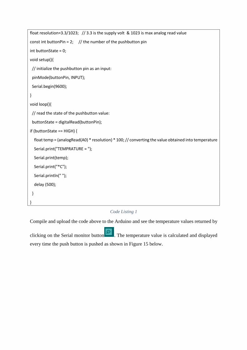
float resolution=3.3/1023; // 3.3 is the supply volt & 1023 is max analog read value
const int buttonPin = 2; // the number of the pushbutton pin
int buttonState = 0;
void setup(){
// initialize the pushbutton pin as an input:
pinMode(buttonPin, INPUT);
Serial.begin(9600);
}
void loop(){
// read the state of the pushbutton value:
buttonState = digitalRead(buttonPin);
if (buttonState == HIGH) {
float temp = (analogRead(A0) * resolution) * 100; // converting the value obtained into temperature
Serial.print("TEMPRATURE = ");
Serial.print(temp);
Serial.print("*C");
Serial.println(" ");
delay (500);
}
}
Code Listing 1
Compile and upload the code above to the Arduino and see the temperature values returned by
clicking on the Serial monitor button . The temperature value is calculated and displayed
every time the push button is pushed as shown in Figure 15 below.

Figure 15

SUMMARY
This unit outlined the different layers of the IoT Architecture, namely the physical layer for
devices, the gateway layer for external communication, the integration layer for storage and
application layer for processing and presentation. The different communication protocols used
at the different layers of an IoT system, namely, physical, network, transport and application
layers have also been analysed.
REFERENCES
1. Postscapes.com. (2017). IoT Standards & Protocols Guide | 2018 Comparisons on
Network, Wireless Comms, Security, Industrial. [online]
Available at: https://www.postscapes.com/internet-of-things-protocols/ [Accessed 26
May 2018]
2. Sundmaeker, H. (2010). Vision and challenges for realising the Internet of Things.
Luxembourg: Publications Office of the European Union.
3. Shi-Wan, L., Miller, B. and Durand, J. (2017). The Industrial Internet of Things Volume
G1: Reference Architecture. 1st ed. [ebook] Industrial Internet Consortium.
Available at: https://www.iiconsortium.org/IIC_PUB_G1_V1.80_2017-01-31.pdf
[Accessed 9 Jun. 2018]
4. Carrez, F. (2018). Open Platforms – IoT-A Architectural Reference Model. [online]
Open-platforms.eu.
Available at: http://open-platforms.eu/standard_protocol/iot-a-architectural-reference-
model/ [Accessed 9 Jun. 2018]
5. Walter, J. (2017). The essential building blocks of an IoT architecture. [online] Mobile
Business Insights.
Available at: https://mobilebusinessinsights.com/2017/09/the-essential-building-
blocks-of-an-iot-architecture/ [Accessed 11 Jun. 2018]