unit 1bytes.usc.edu/files/ee109/slides/sp18/ee109unit1...1.8 kirchhoff's laws •...
TRANSCRIPT
1.1
Unit 1
Circuit Basics
KVL, KCL, Ohm's Law
LED Outputs
Buttons/Switch Inputs

1.2
VOLTAGE AND CURRENT

1.3
Current and Voltage• Charge is measured in units of Coulombs
• Current – Amount of charge flowing through a specific point in a certain time period– Measured in Amperes (A) = Coulombs per
second
– Current is usually denoted by the variable, I
• Voltage – Electric potential energy – Analogous to mechanical potential energy
(i.e. F = mgh)
– Must measure across two points
– Measured in Volts (V)
– Common reference point: Ground (GND) = 0V• Often really connected to the ground
Conductive Material
(A Wire)
-
-
--
-- -
--
-
--
-
Higher
Potential
Lower
Potential
5V
3V
GND
Higher
Potential
Lower
Potential

1.4
Current / Voltage Analogy
Voltage Source =
Water Pressure
+
+
+
Charge =
Water
U2
U
1U3
+ v2 -
-v
1 +
+ v
3 -
i

1.5
Meet The Components
• Most electronic circuits are modeled with the following components
• Resistor
– Measures how well a material conducts electrons
• Capacitor & Inductor
– Measures material's ability to store charge and energy
• Transistor
– Basic amplification or switching technology
C
R
L
Transistor

1.6
Kirchhoff's Laws• Common sense rules that govern
current and voltage– Kirchhoff's Current Law (KCL)
– Kirchhoff's Voltage Law (KVL)
• Kirchhoff's Current Law (KCL)– The current flowing into a location (a.k.a.
node) must equal the current flowing outof the location
– …or put another way…
– The sum of current at any location must equal 0
i1 i2
i3i4
KCL says i1 + i2 = i3 + i4
An electronic
component (e.g.
resistor, transistor, etc.)
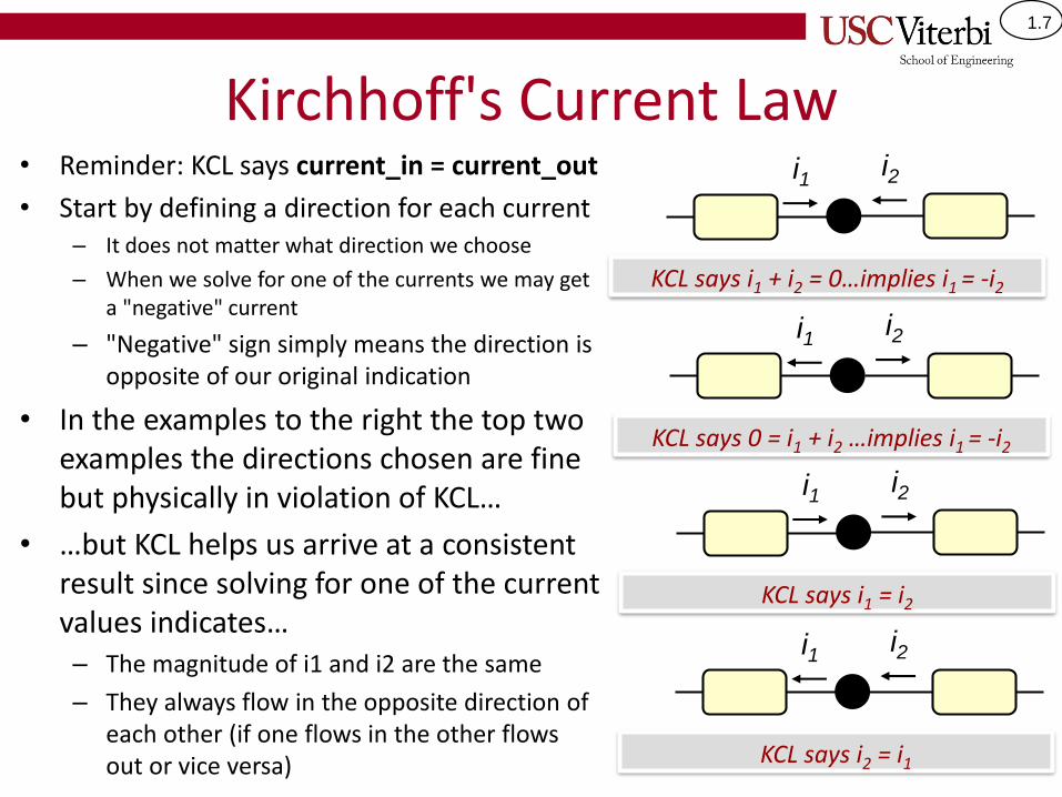
1.7
Kirchhoff's Current Law• Reminder: KCL says current_in = current_out
• Start by defining a direction for each current – It does not matter what direction we choose
– When we solve for one of the currents we may get a "negative" current
– "Negative" sign simply means the direction is opposite of our original indication
• In the examples to the right the top two examples the directions chosen are fine but physically in violation of KCL…
• …but KCL helps us arrive at a consistent result since solving for one of the current values indicates…– The magnitude of i1 and i2 are the same
– They always flow in the opposite direction of each other (if one flows in the other flows out or vice versa)
KCL says i1 + i2 = 0…implies i1 = -i2
i1 i2
KCL says 0 = i1 + i2 …implies i1 = -i2
i1 i2
KCL says i2 = i1
i1 i2
KCL says i1 = i2
i1 i2
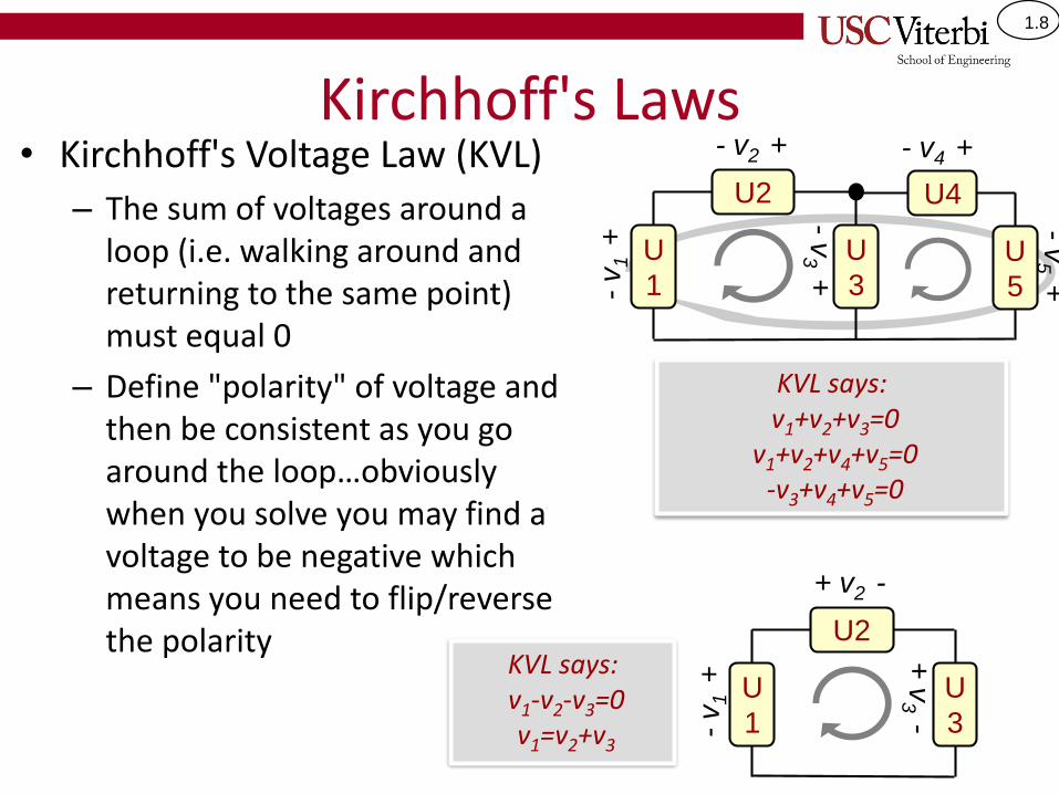
1.8
Kirchhoff's Laws• Kirchhoff's Voltage Law (KVL)
– The sum of voltages around a loop (i.e. walking around and returning to the same point) must equal 0
– Define "polarity" of voltage and then be consistent as you go around the loop…obviously when you solve you may find a voltage to be negative which means you need to flip/reverse the polarity
KVL says:v1+v2+v3=0
v1+v2+v4+v5=0-v3+v4+v5=0
U2
U
1
U4
U
3U
5
- v2 + - v4 +
-v
1 +
-v
3 +
-v
5 +
U2
U
1
U
3
+ v2 -
-v
1 +
+ v
3 -
KVL says:v1-v2-v3=0v1=v2+v3
1.9
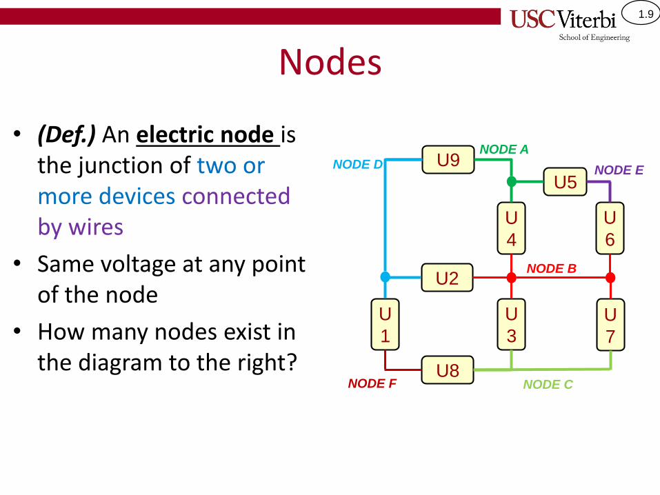
Nodes
• (Def.) An electric node is the junction of two or more devices connected by wires
• Same voltage at any point of the node
• How many nodes exist in the diagram to the right?
U2
U
1
U
3U
7
U8
U
4
U5
U
6
NODE D
NODE B
U9NODE A
NODE E
NODE F NODE C

1.10
Practice KCL and KVL
• Use KCL to solve for i3, i4, and i6
– Node A: i9 = i4 + 1A• 2 Unknowns…find another node
– Node D: i9 = 1A+1A = 2A
– Node A: 2A = i4 + 1A, thus i4=1A
– Node C: 0.5A +i3 = i8• i8 must be 1A so i3 = 0.5A
– Node B: i4 + i6 = 1A + i3 + 0.5A• i3 is 0.5A, i4 is 1A, and i6 has to be 1A
• So check: 2A = 1A + 0.5A + 0.5A
• Use KVL to solve for v3, v8, v5– Loop {U3,U7}: -V3 + -5V = 0
• V3 = -5V
– Loop {U5,U6,U4}: -V5 - 3V + 4V = 0• V5 = 1V
– Loop {U1,U2,U3,U8}: 2V + 5V + (-5V) - v8 = 0
• V8 = 2V
Hint: Find a node or loop where there is only one unknown and that should
cause a domino effect
U2
U
1
U
3U
7
- 5V +
-2
V +
-v
3 +
+ 5
V -
U8
U
4
U5
+ v5 -
U
6
- v8 +
+ 3
V -
+ 4
V -
1A
1A
1A
i4
i3
0.5A
i6
NODE D
NODE B
NODE C
U9
- 9V +
i9 NODE A
i8

1.11
Resistance and Ohms Law• Measure of how hard it is
for current to flow through the substance
• Resistance = Voltage / Current– How much pressure do you
have to put to get a certain current to flow
• Measured in Ohms (Ω)
• Ohm's Law– I = V/R or V = IR
– R ↑ => I ↓Schematic Symbol for
a Resistor
R
Small
Resistance
Large
Resistance
http://usc.scout.com/2/926916.html
http://www.zimbio.com/photos/Marquise+Lee/Oregon+v+USC/9qQqBuy838Z

1.12
Series & Parallel Resistance• Series resistors = one
after the next with no other divergent path
• Parallel resistors = Spanning the same two points
• Series and parallel resistors can be combined to an equivalent resistor with value given as shown…
Series Connections
Parallel Connection
R1 R2
R=R1+R2
R1 R2
𝑅𝑒𝑓𝑓 =1
𝑅1+
1
𝑅2
−1
=1
1𝑅1
+1𝑅2
Reff = R1 + R2
Reff

1.13
Solving Voltage & Current• Given the circuit to the right, let…
– Vdd = +5V, R1 = 400 ohms, R2 = 600 ohms
• Solve for the current through the circuit and voltages across each resistors (i.e. V1 and V2)
– Since everything is in series, KCL teaches us that the current through each component must be the same, let's call it i
• i = Vdd / (R1 + R2) = 5/1000 = 5 mA
– This alone lets us compute V1 and V2 since Ohm's law says
• V1 = i*R1 and V2 = i*R2
• V1 = 2V and V2 = 3V
– Though unneeded, KVL teaches us that
• Vdd-V1-V2=0 or that Vdd = V1 + V2
+
_
R1
R2Vdd
+ V1 -
+ V
2 -
i

1.14
Voltage Supply Drawings• The voltage source (Vdd) in the left diagram (i.e.
the circle connected to the "Rest of Circuit") is shown in an alternate representation in the right diagram (i.e. the triangle labeled "Vdd")
• In the left diagram we can easily see a KVL loop available
• There is still a KVL loop available in the right diagram
+
_
R1
R2Vdd
+ V1 -
+ V
2 -
iVdd
R2
+ V
2 -
R1
+ V
1 -
i
This diagram is an
equivalent to the one
above.
Actual
connection…
…will be drawn
like this
Vdd Rest of
Circuit

1.15
Voltage Dividers• Original Problem
– Vs = +5V, R1 = 400 ohms, R2 = 600 ohms
• Recall our solution
– i = Vs / (R1 + R2) = 5/1000 = 5 mA
– V1 = i*R1 = 2V and V2 = i*R2 = 3V
• When two resistors are in series we can deduce an expression for the voltage across one of them
– i = Vtot / (R1 + R2)
– V1 = i*R1 and V2 = i*R2
– Substituting our expression for i:
𝑉1 = 𝑉𝑡𝑜𝑡𝑅1
𝑅1 + 𝑅2𝑎𝑛𝑑 𝑉2 = 𝑉𝑡𝑜𝑡
𝑅2
𝑅1 + 𝑅2
• The voltage across one of the resistors is proportional to the value of that resistor and the total series resistance
– If you need 10 gallons of gas to drive 500 miles, how much gas you have you used up after driving 200 miles?
• Gas = Voltage, Milage = Resistance
R1 R2
+V1- +V2-
i
+ Vtot -
If two resistors Rx and Ry
are in series then voltage
across Rx is:
Vx = Vtot * Rx / (Rx + Ry)
Memorize this. We will use it often!
1.16
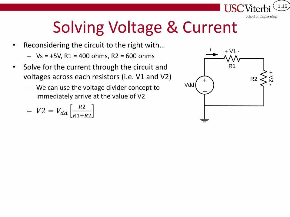
Solving Voltage & Current• Reconsidering the circuit to the right with…
– Vs = +5V, R1 = 400 ohms, R2 = 600 ohms
• Solve for the current through the circuit and voltages across each resistors (i.e. V1 and V2)
– We can use the voltage divider concept to immediately arrive at the value of V2
– 𝑉2 = 𝑉𝑑𝑑𝑅2
𝑅1+𝑅2
+
_
R1
R2Vdd
+ V1 -
+ V
2 -
i
1.17
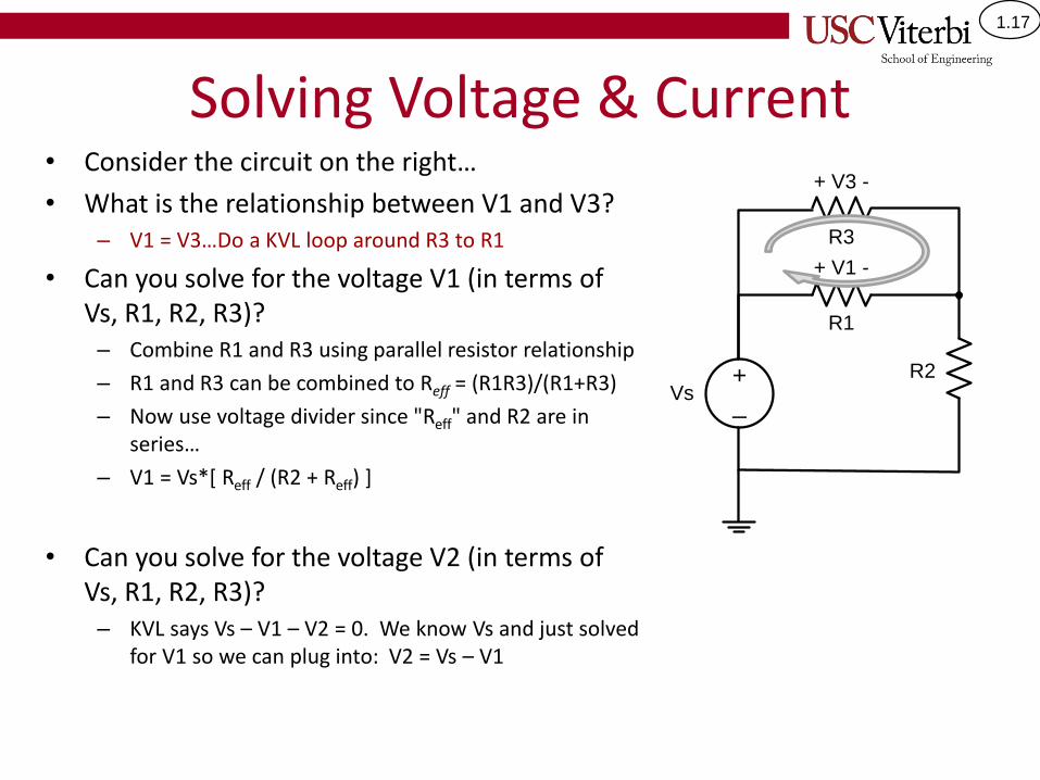
Solving Voltage & Current• Consider the circuit on the right…
• What is the relationship between V1 and V3?– V1 = V3…Do a KVL loop around R3 to R1
• Can you solve for the voltage V1 (in terms of Vs, R1, R2, R3)?
– Combine R1 and R3 using parallel resistor relationship
– R1 and R3 can be combined to Reff = (R1R3)/(R1+R3)
– Now use voltage divider since "Reff" and R2 are in series…
– V1 = Vs*[ Reff / (R2 + Reff) ]
• Can you solve for the voltage V2 (in terms of Vs, R1, R2, R3)?
– KVL says Vs – V1 – V2 = 0. We know Vs and just solved for V1 so we can plug into: V2 = Vs – V1
+
_
R1
R2Vs
+ V1 -
R3
+ V3 -

1.18
A Problem…• Given the following parameters…
– Vs=5V, R1=4, R2 = 12, R3 = 2 and R4 = 10 ohms.
• Can we use the voltage divider concept to immediately solve the voltage across R2 or do we need to first do some manipulation? What about R4?
• First, find the total equivalent resistance (Req) seen by Vs and then solve for the voltage across each resistor
First collapse this to a single
equivalent resistance, Req
Rtot = R1+[R2*(R3+R4)]/[R2+R3+R4]
= 10 ohms
i1 = Vs / Rtot = 5/10 = 0.5A
V1 = i1*R1 = 2V
V2 = 5V – 2V = 3V (using KVL)
V3 = 3 * 2/(2+10) (volt. divider)
= 3V * 1/6
= 0.5 V
V4 = V2 * R4/(R3 + R4) (volt. divider)
= 3V * 5/6
= 2.5V

1.19
LEDS AS OUTPUTS AND SWITCHES/BUTTONS AS INPUTS
1.20
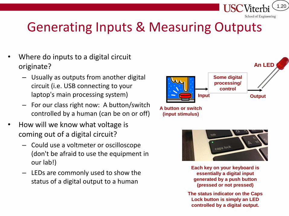
Generating Inputs & Measuring Outputs
• Where do inputs to a digital circuit originate?
– Usually as outputs from another digital circuit (i.e. USB connecting to your laptop's main processing system)
– For our class right now: A button/switch controlled by a human (can be on or off)
• How will we know what voltage is coming out of a digital circuit?
– Could use a voltmeter or oscilloscope (don't be afraid to use the equipment in our lab!)
– LEDs are commonly used to show the status of a digital output to a human
Each key on your keyboard is
essentially a digital input
generated by a push button
(pressed or not pressed)
The status indicator on the Caps
Lock button is simply an LED
controlled by a digital output.
Input
A button or switch
(input stimulus)
An LED
Output
Some digital
processing/
control

1.21
(Light-Emitting) Diodes
• The simplest output we can control is an LED (Light-emitting diode) which is like a tiny light bulb
• An LED glows ('on') when current flows through it (i.e. when there is a voltage difference across it)
• LEDs are polarized meaning they only work in one orientation (longer leg must be at higher voltage)
http://www.custobots.com/sites/def
ault/files/imagecache/product_full/p
roducts/Solarbotics-redLED.gif
Longer leg connects
to the side with the
higher voltage
Shorter leg connects
to the side with the
lower voltage
+ VLED -
LED Schematic
Symbol
Longer
leg
Shorter
leg
+ VLED -
+5V +0V
Current flows = LED on
+5V +0V
BACKWARDS!! No Current
flows = LED off
+ VLED -
+0V +0V
No voltage differential =
No Current flows = LED off
+ VLED -
+5V +5V
Main Point: The long leg of the LED must be attached to the side that will have the higher voltage.

1.22
Need for Series Resistor with LEDs• Problem: LEDs may allow too much current to flow which
may blow out the LED
• Solution: Use a series resistor to limit current
– Amount of current will determine brightness of LED
– R↑ then i↓ and thus LED brightness ↓
– i = V1/R1 = (Vs-VLED) / R1
– Usually R1 is a few hundred ohms (330 or 470 ohms)
No current
limitation…BAD
Choose resistor to
limit current
Doesn't matter where
resistor is placed as
long as it is in series
+ VLED -
LED Schematic
Symbol
Breadboard view
A digital (gate) output will usually serve as our voltage
source that can be either '0' (0V) or '1' (5V)
Longer
leg
Shorter
leg
Main Point: LED's should always be connected in series with a current-limiting resistor

1.23
LED Connection Approaches• When letting a digital output control an LED, the value
(i.e. '0' = low or '1' = high voltage) that causes the LED to light up depends on how the circuit is wired
– Note: Gates can often "sink" (take in) more current than they can "source" (push out), so option 2 may be preferred…but let's not worry about this now…let's use option 1
LED is on when
gate outputs '1'
LED is on when
gate outputs '0'
This box
represents a
digital output (e.g.
your Arduino) that
can generate a
high (1) or low (0)
voltage.
What digital
output value must
be present for the
LED to be on?
Main Point: LED's can light for either a logic '1' or '0' output…it depends on how they are wired.
Option 2Option 1Model of digital
outputVdd
GND
+ V
LE
D -
1
0
R
Vdd
GND
+ V
LE
D -
Vdd
1
0
R
LED off
LED on
LED on
LED off

1.24
Switch and PushButton Inputs
• Switches and pushbuttons can be in one of two configurations: open or closed
– Switches can be opened or closed and then stay in that position until changed
– Pushbuttons are open by default and require you to push them to close the circuit (they then open when you release)
• Can be used as an input to digital device
Example pushbuttons
Example switch

1.25
Switches and Pushbuttons• Important Note 1:
– When open a SW/PB looks like an infinite resistance (no current can flow)
– When closed a SW/PB looks like a wire (R=0) and no voltage drops across it
• Question: What voltage does an open or closed switch (pushbutton) generate?
• Answer: NOTHING.
• Important Note 2: – SW or PBs don't produce digital 0's or 1's on their
own, they control what voltage (PWR/GND) is connected to your device
SW
R=inf.
(open circuit)
SW
R=0
(wire)
=
=
SW
SW
V = ??
V = ??

1.26
Connecting a Switch• Switches only help control the voltage going
into a device, they do not produce a voltage (0V or 5V) by themselves
• Option 1: Attach one side to GND and the other side to the device– When the switch=open, nothing is connected to
the device (a.k.a. “floating”)
– A floating input may sometimes appears as zero, and other times as a one.
– We need the inputs to logic gates to be in either the 0 or 1 state…not floating
• Option 2:– When switch closed => low resistance connection
from power to ground = LARGE current flow…BAD!!! (This is known as a "short circuit").
Option 1: Bad (floating)
SW
R ≈ inf.
Arduino
input model
Vin = floating =
unknown
Vin
Option 2: Bad
(short circuit)
Arduino
input model
R ≈ inf.
Vdd
SW
Unlimited
current flow
when closed
Switch Closed = 0V (Logic 0) to input
Switch Open = ??? (does not work)
Switch Open = Vdd=5V (Logic 1) to input
Switch Closed = Short Circuit
(does not work)
1.27
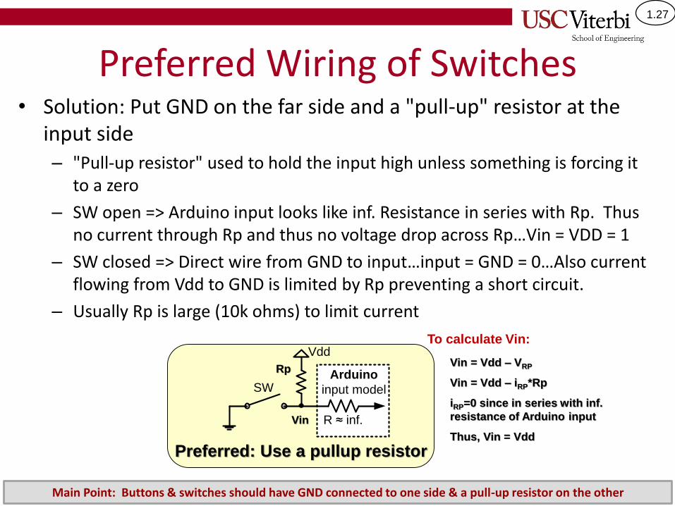
Preferred Wiring of Switches• Solution: Put GND on the far side and a "pull-up" resistor at the
input side – "Pull-up resistor" used to hold the input high unless something is forcing it
to a zero
– SW open => Arduino input looks like inf. Resistance in series with Rp. Thus no current through Rp and thus no voltage drop across Rp…Vin = VDD = 1
– SW closed => Direct wire from GND to input…input = GND = 0…Also current flowing from Vdd to GND is limited by Rp preventing a short circuit.
– Usually Rp is large (10k ohms) to limit current
Preferred: Use a pullup resistor
Vdd
SW
R ≈ inf.
Arduino
input model
Rp
Vin
Vin = Vdd – VRP
Vin = Vdd – iRP*Rp
iRP=0 since in series with inf.
resistance of Arduino input
Thus, Vin = Vdd
To calculate Vin:
Main Point: Buttons & switches should have GND connected to one side & a pull-up resistor on the other

1.28
Power & Ground Connections• Easy mistake when you're just learning to wire up circuits:
– Wire the inputs & outputs but forget to connect power and ground
• All circuits and chips require a connection to a power source and ground– Digital circuits (aka "gates")
– Switches
– Buttons
Actual
connection…
…will be drawn
like this
Vdd Rest of
Circuit
Vdd
GND
Rest of
Circuit
Digital
Circuit
Vdd
GND
Digital
Circuit