unit 12
DESCRIPTION
Unit 12. Timer Examples. Example – Music Generation. Channel 6 – Set up as a timer Output to Generate Square Waves Channel 4 – Set up as a timer Output to control the length of each tone. Free-running counter will have a time resolution of 1 Microsecond. Music Generation. Output 6 - PowerPoint PPT PresentationTRANSCRIPT

Unit 12
Timer Examples

Example – Music Generation
• Channel 6 – Set up as a timer Output to Generate Square Waves
• Channel 4 – Set up as a timer Output to control the length of each tone.
• Free-running counter will have a time resolution of 1 Microsecond

Music Generation
1 SecOutput 4
1 SecOutput 4
1 SecOutput 4
1 SecOutput 4
Output 6FrequencyF1
Output 6FrequencyF2
Output 6FrequencyF3
Output 6FrequencyF4

Details of implementation
• Channel 4 is used to generate an Interrupt every 50 milliseconds
– 20 interrupts = 1 second– Select a new frequency for Channel 6’s output at end
of each 1 second interval
• Prescale value of 2 is used to provide 1 MHZ clock to free-running counter
- Unit clock period is therefore 1 microsecond

Frequency of Notes
Note Frequency Period (usec)
C 262 3816.8
C# 272 3676.5
D 294 3401.4
D# 311 3215.4
E 330 3030.3
F 349 2865.3
F# 369 2710.0
G 392 2551.0
G# 415 2409.6
A 440 2272.7
A# 466 2145.9
B 495 2020.2

Software Initialization
----// forward references to interrupt service routinesvoid oc6_isr(void) __attribute__ ((interrupt)); // IC6 Interruptvoid oc4_isr(void) __attribute__ ((interurpt)): // IC4 interrupt--------// global variables – period of each noteunsigned int freq[12] = 3817, 3677, 3401, 3215, 3030, 2865, 2710,2551, 2410, 2273, 2146, 2020;// global variable - songunsigned char music[13] = 0,1,2,3,4,5,6,7,8,9,10,11,0xFF;//index of notes in song--12 notes plus end flag----unsigned int tp4 = 50000; //50 millisecondsunsigned int tp6 = 3817/2; // half period for C noteunsigned idx1=0, idx2=0;----

Main Program
int main(){ --- TSCR2 = 0x01; // 1 usec resolution with TNCT,using
// prescale factor of 2 on internal 2 MHz clock // No TOF Interrupt
---- // initialize Channel 6 for generating square wave ---- // initialize Channel 4 for control of interval length for each note --- ENABLE(); // enable interrupts---- }

Initialize Channel 6
/* Initialize Output Compare Channel 6 Complement on Each Compare Timer has been initialized */
TIOS = TIOS | 0x40: // Set Channel 6 to Output Compare – Bit 6// TIOS = x1xx xxxx
TCTL1 = (TCTL1&0xCF) | 0x10; // Toggle Output Line 6 (square wave)// TCTL1 = xx01 xxxx
TFLG1 = 0x40; // Clear Channel 6 Flag
TC6 = TCNT + tp6; // Complement in tp6 SecondsSet earlier to be half period of C Note

Using Interrupts for Channel 6 Task
SETVECT(0xFFE2, oc6_isr); // set interrupt vector
TIE = TIE | 0x40; // Enable Channel 6 Interrupt--------void oc6_isr(void)
{// Period of square wave is 2*tp6
TC6 = TC6 + tp6; // Next interrupt set up for tp6 from now
TFLG1 = 0x40; // Clear Channel 6 Flag}

Initialize Channel 4
/* Initialize Output Compare Channel 4 Complement on Each Compare Timer has been initialized */
TIOS = TIOS | 0x10: // Set Channel 4 to Output Compare – Bit 4// TIOS = xxx1 xxxx
TCTL1 = (TCTL1&0xFC) | 0x01; // Toggle Output Line 4// TCTL1 = xxxx xx01 – Toggle Pin 4
TFLG1 = 0x10; // Clear Channel 4 Flag
TC4 = TCNT + tp4; // Complement in tp4 Seconds// tp4 = 50 000 microseconds

Using Interrupts for Channel 4 Task
SETVECT(0xFFE6, oc4_isr); // set interrupt vectorTIE = TIE | 0x10; // Enable Channel 4 Interrupt-------- initially set to 50000void oc4_isr(void){TC4 = TC4 + tp4; // Complement T from now and generate
// interrupts 20 times per second TFLG1 = 0x10; // Clear Channel 4 Flag idx0++; // Count Channel 4 interrupts up to 20 if(idx0>20) initially set to 0 { // 1 second has elapsed idx0=0; idx1++; //bump up index to next note if (music[idx1]==0xFF)idx1=0; tp6 = freq[music[idx1]]/2; // select period of next note }}

ECE 371 Timer Example
Rotary Dial Telephone
Decode Dial Digits

Rotary Dial
• If not using phone, telephone presents an open circuit and no current flows.
• If telephone is in use, then current flows since there is a DC voltage of 48 volts on line. Phone appears as a 600 to 900 Ohm resistor.
• Rotary dial opens the line for 1/20 seconds for each pulse.

Rotary Dial Telephone
Old Rotary Dial Phones generated 1 to 10 pulse each time a numberWas dialed. The pulse rate was 10 pulses per second with a .3 secondInterval between successive digits.
The Dial opens the line for about 1/20 second for each digit.
Let Channel 0 detect and count the 0->1 transitionsLet Channel 1 detect the gap between digits
1 pulse for digit 1 2 pulses for
digit 2
3 pulses for digit 3
.3 sec .1 sec
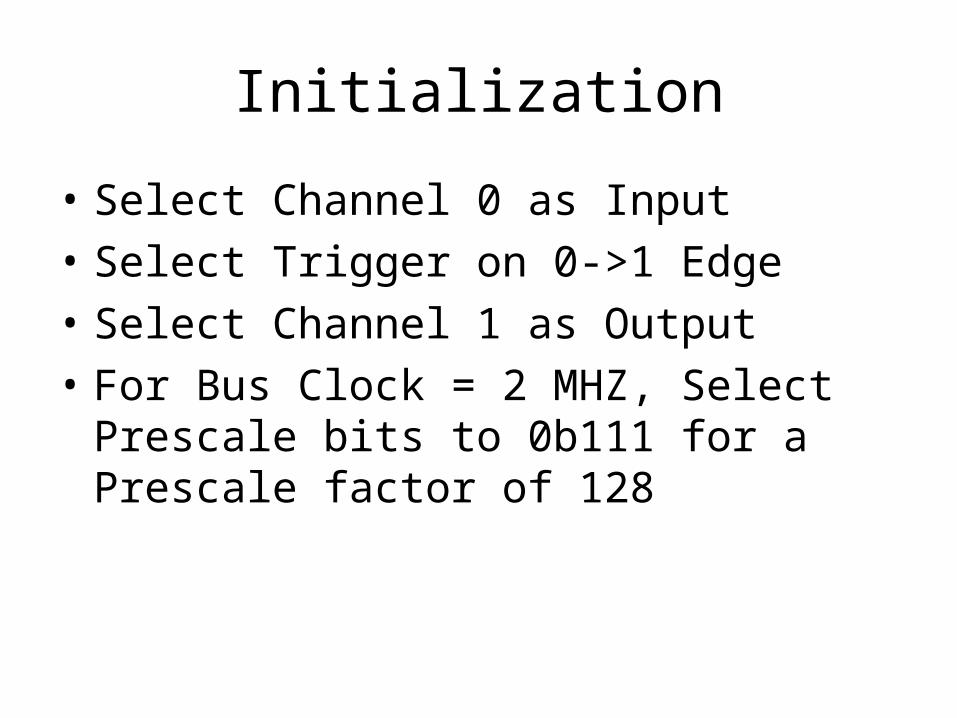
Initialization
• Select Channel 0 as Input
• Select Trigger on 0->1 Edge
• Select Channel 1 as Output
• For Bus Clock = 2 MHZ, Select Prescale bits to 0b111 for a Prescale factor of 128

2,000,000128 = 15,625 = frequency of scaled clock
1
15,625= period of divided clock
Let x = initialization value for Counter 1
Solve for x:
115,625
x = .2
x = .2 (15,625) = 3,125
3,12510 = 0x0C35

//Global Variablesunsigned int idx0 = 0; //count of pulses for each digit dialedunsigned int idx1 = 0; //count of number of digits dialedunsigned char digit[20]; //accept maximum of 20 dialed digits---//interrupt handler for channel 0void ic0_isr(void)
{ TFLG1 = 0x01; // clear channel 0 flag
TC1 = TC0 + 0x0C35; // Insert new time in channel 1 (for an interrupt in .2 sec)// If channel 1 interrupt before channel 0, then gap found idx0++; // increment pulse counter TFLG2=0x02; // clear channel 1 flag TIE = TIE | 0x02; // enable interrupts from channel 1}

// channel 1 interrupt service routine// Gap between digits is found
void oc1_isr(void)
{if(idx1<20) {// prevent buffer overflow digit[idx1++] = idx0; // save count idx0 = 0; TFLG1 = 0x02; // clear flag TIE = TIE & 0xFD; // disable interrupts }}
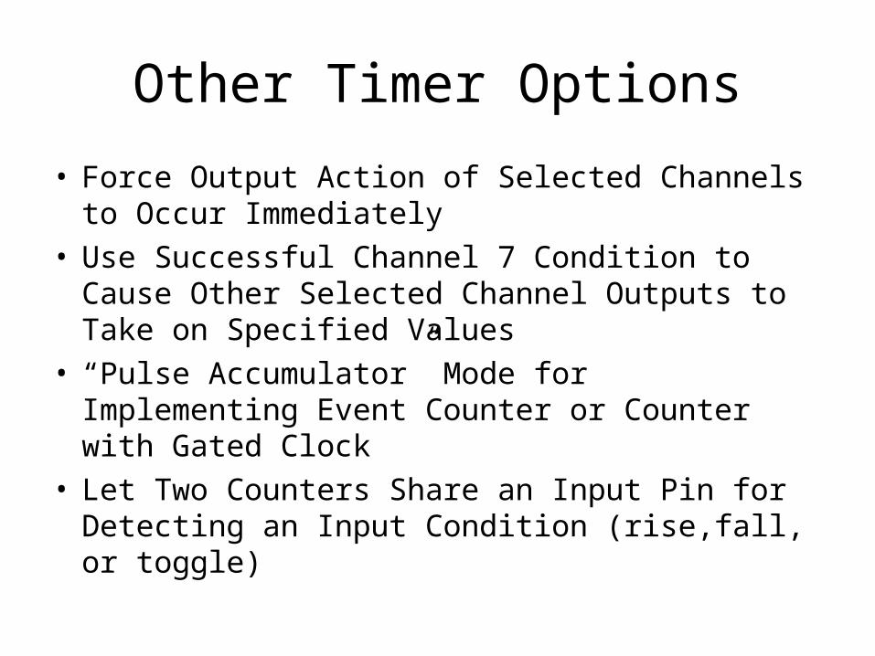
Other Timer Options
• Force Output Action of Selected Channels to Occur Immediately
• Use Successful Channel 7 Condition to Cause Other Selected Channel Outputs to Take on Specified Values
• “Pulse Accumulator” Mode for Implementing Event Counter or Counter with Gated Clock
• Let Two Counters Share an Input Pin for Detecting an Input Condition (rise,fall, or toggle)

Timer Compare Force Register

CFORC Example
// Channel 6, 3, 2, 0 are selected as OutputsCFORC = 0x05; // Force Output Actions on Channel 0 and 2// Does not set flags for interrupt request
// CFORC = 0x44; // Force Output Actions on Channel 3 and 6// Does not set flags for interrupt request

Output Compare on Channel 7
• Option of sending new values to all or any subset of Output Pins
• OC7M Selects Output Pins
• OC7D Select New State of Selected Pins
• Can Reset TNCT if TCRE=“1”
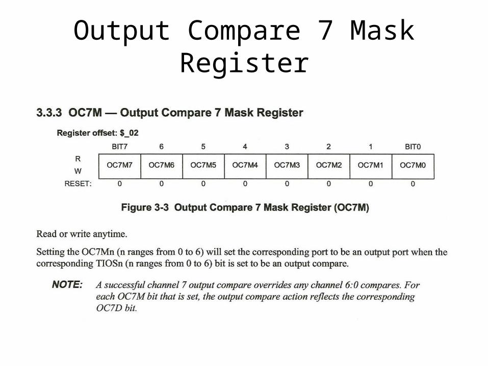
Output Compare 7 Mask Register

Output Compare 7 Data Register


Example of Application of “Output Compare on Channel 7”:
Generate Pulse Width Modulation (PWM) Signals
• Period Can Be Specified by OC7
• Width of Pulse Generated at Output I Can Be Specified by OCi

0 0x4000 0x8000 0xC000 0x4000 0x8000 0xC000
0 TCNT 0 TCNT 0
OC7
OC4
OC2

Example OC7 and TCRE=1
TIOS = TIOS | 0x94 ;//Select Channel 2, 4, 7 as Outputs
OC7M = 0x14; // Select Channel 4 and 2OC7D = 0x04; // Clear Channel 4 and Set Channel 2
TC7 = 0xC000;TC4 = 0x4000;TC2 = 0x8000;
TCTL1= (TCTL1&0x3C) | 0x41; //0b0100 0001 - Ch 7 and 4// TCTL1 = 01xx xx01 - toggle Ch 7 and 4
TCTL2= (TCTL2&0xCF) | 0x10; //0b0001 0000 - Ch2// TCTL2 = xx01 xxxx - toggle Ch 2
TSCR2=0x09; // 0b00001001 – TCRE=1, Prescale=1
“Alarm Clock” values for Channels 2, 4, 7

Pulse Accumulators
• 4 8-bit Pulse Accumulator– PAC0, PAC1, PAC2, PAC3– Pin 0, 1, 2, and 3 of Port T serve as inputs for
PACO, PAC1, PAC2, and PAC3
• Accumulators are incremented on selected edge on pin
• TCTL4 selects edge detector algorithm– Rise, fall, either


Delay Algorithm
• If 0->1 is selected edge, then input must be 1 after delay for Pulse Accumulator to be incremented
• If 1->0 is selected edge, then input must be 0 after delay for Pulse Accumulator to be incremented

Pulse Accumulator Enable

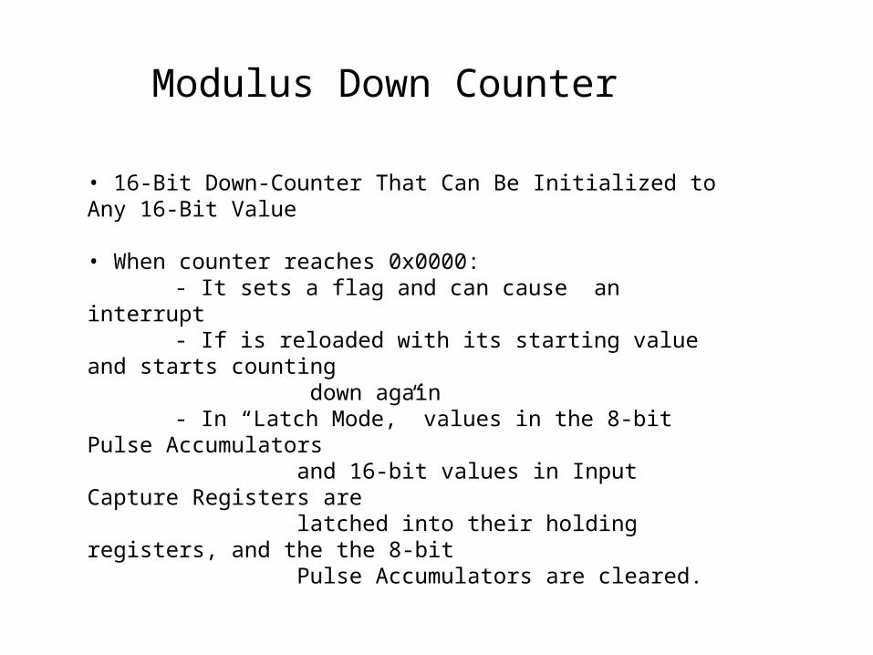
Modulus Down Counter
• 16-Bit Down-Counter That Can Be Initialized to Any 16-Bit Value • When counter reaches 0x0000:
- It sets a flag and can cause an interrupt- If is reloaded with its starting value and starts counting
down again- In “Latch Mode,” values in the 8-bit Pulse Accumulators
and 16-bit values in Input Capture Registers are latched into their holding registers, and the the 8-bit Pulse Accumulators are cleared.

Buffered Mode
• Holding registers for Input Capture and Pulse Accumulators are enabled.
• Permits 2 input captured values prior to interrupt
• Enabled by setting BUFEN=“1” in ICSYS
• Channels 0, 1, 2, and 3 support Buffered Mode

Buffered Mode (cont)
• Latching mode controlled by LATQ bit in ICSYS - LATQ = 0: Queue Mode: Latch on second edge (second pulse)
- LATQ = 1: Latch Mode: Latch when Modulus Down Counter = 0
Note: When LATQ = 1 in Buffered Mode, a latching operation can be forced by setting a “1” to the ICLAT in the MCCTL control register.

SH37 – Pin 3 in input to Channel 3 and 7 concurrentlySH26 – Pin 2 is input to Channel 2 and 6 concurrentlySH15 – Pin 1 is input to Channel 1 and 5 concurrentlySH04 – Pin 0 is input to Channel 0 and 4 concurrently

1 = Latch Mode is enabled. Latching occurs when modulus down-counter reaches zero or a zero is written into the count register MCCNT. When a latching event occurs, the contents of the Input Capture Registers and the 8-bit pulse accumulators are transferred to their Holding Registers and the 8-bit Pulse Accumulators are cleared.
