unique way of replacing main counterweight ropes
TRANSCRIPT

HEAVY MOVABLE STRUCTURES, INC.
TENTH BIENNIAL SYMPOSIUM
OCTOBER 25 - 28, 2004The Omni Orlando Resort at ChampionsGate
Unique Way Of Replacing Main Counterweight RopesBurlington Canal Lift BridgeBurlington, Ontario, Canada
Abbas Khan, P.Eng. & Clare LamontPublic Works and Government Services of Canada
John Low, P.Eng.Stantec Consulting Inc.
David O. Nyarko, P.E.Parsons Brinckerhoff Inc.
Ownership/Public Use/Management
Paper No. 10

TABLE OF CONTENTS
INTRODUCTION ................................................................................................................................. 3Background .......................................................................................................................................... 3Schedule and Challenges ........................................................................................................................ 3ROPE FABRICATON ........................................................................................................................... 4Replacement criteria ............................................................................................................................... 5ROPE DESIGN CRITERIA .................................................................................................................... 5ROPES REPLACEMENT ...................................................................................................................... 6WEIGHING THE LIFT SPAN ................................................................................................................ 6DETERMINING BRIDGE IMBALANCE ................................................................................................. 6READJUSTING THE CONTROLLED TORQUE COUPLINGS ................................................................... 6CONSTRUCTION SCHEME ................................................................................................................. 7ROPE TENSIONING ............................................................................................................................ 7ROPE TESTING .................................................................................................................................. 7ROPE LUBRICATION .......................................................................................................................... 7SEATING OF LIFT SPAN ..................................................................................................................... 7CONCLUSION .................................................................................................................................... 8
INTRODUCTION The Burlington Canal Lift Bridge is a tower driven steel truss bridge which was constructed in1962. Between 1962 and 2000 the bridge was raised in excess of 160,000 allowing thesafe passage of some 280,000 vessels to and from the Hamilton Harbor. The 2000 tonnes spanis 161 m long, and lifts 33.5 m, at a speed of 18m/ min. It was a tight schedule with ten weeksavailable for construction in a Canadian winter for the replacement of 80 main counterweightwire ropes. The ropes were 57 mm diameter, 6 x 19 classification, 6 x 25 Filler Wire construc-tion with an independent polypropylene core with a minimum ultimate strength of 420 kips. The bridge provides a vital link between Hamilton Harbour and Lake Ontario through the Burling-ton Canal for vessels entering Hamilton Harbour and vehicle traffic at 5450 AADT between thecities of Burlington and the Hamilton. The Bridge is operated around the clock, seven days aweek, and performs on average 4200 lifts per year The design and contract administration was carried out by the original designers, Stantec Con-sulting Ltd (C.C. Parker and Associates) and Parsons Brinckerhoff Quade & Douglas, Inc. Con-struction work was carried out by Ross Contractors & Engineers of Sarnia, The ropes weremanufactured by Briden America. Although not the first wire rope replacement on a lift bridge,this project was by no means routine. Unique problems arose during construction least of whichwas one of the coldest winter on record, or preparation for a 30 km traffic diversion in the eventof bad weather. The contractor used unique yet simple methods to remove and install the ropes,without the use of high cranes or and barges. One consideration was to work on one towereach winter. However, extension over two winters would have multiplied the complexity of traf-fic diversion and construction costs substantially.
Background The Burlington Canal Lift Bridge is located on the western shore of Lake Ontario on a site richhistory. The bridge spans the Burlington Canal that was opened in 1826.Once a narrow cut, the canal now provided Burlington Bay at the head of Lake Ontario withnavigable access to the Atlantic Ocean. The canal connected the Hamilton Harbour industrial re-gion to international trade and commerce. It was among a series of waterway projects to pro-vide navigation from Lake Erie to the Atlantic Ocean begun 200 years ago. Today, the BurlingtonCanal remains a busy waterway and is vital to the area commerce. There were five different movable bridges located on this site since 1830. The present bridgecarries four lanes of vehicular traffic across the canal and was opened to traffic in 1962. Thisstructure originally had tracks for the Hamilton-Northwestern railway. The tracks were removedin 1982 when the roadway was widened. The bridge structure is a tower drive type, vertical lift movable bridge. The lift span is 116 m (380feet) long, 21 m (65 feet) wide, weighs 2000 tonnes (2200 tons), and has a vertical lift of 33.5 m(110 feet). A system of machinery, sheaves, and wire ropes originating at the towers is used tomove the lift span. There is one-150 hp drive motor in each of the two towers to power the ma-chinery and one-150 hp synchro-tie motor in each tower to synchronize the drive motors at eachend of the span.
Schedule and Challenges
The Burlington Canal being the only access into the Hamilton Harbour, provides a vital link be-tween the harbour and international shipping. The Harbour remains closed to commercial ship-ping generally during the period of early January to mid March. In addition to the shipping trafficthe bridge carries Provincial Highway 2 (Eastport Drive) linking the cities of Hamilton and Burling-ton. The main expressway linking the cities is the Queen Elizabeth Way which runs along thehigh Burlington Skyway Bridge. This bridge provides an alternative to vehicular traffic in theevent of the Skyway closure due to high winds or lane closures due to accidents. The preparatory work including rope fabrication was to take 16 to 24 weeks. Project wasawarded in summer to be ready for installation in winter. Several scheduling options were con-sidered, which included;
- Construction during the 10 week winter period when the Bridge is closed to ship-ping
- Rope fabrication and installation under two separate contracts versus one- Replacement of one rope at a time- Replacement of wire ropes on one tower each year (winter construction pe-
riod)- Partial lane closure to vehicular traffic and pedestrians- Total road closure to vehicular traffic and pedestrians
Since the bridge can be closed to shipping only in the winter for about a 10 week period, the dis-cussion was mainly between one or two winter construction periods, and full or partial lane clo-sures. For safety considerations the bridge will be need to be closed to vehicular traffic whenthe bridge is raised to disconnect and lower the existing ropes, and when the new ropes arebeing hoisted up. This closure was estimated to add up to several weeks. Night work and ve-hicular traffic lanes opening and closing was considered too disruptive to the contractors pro-ductivity, and confuse the public. It was considered least disruptive to traffic, safe, most costeffective, shortest construction period and better productivity to give the contractor the fullbridge for a 10 week period and allow full road closure. The main concern was to ensure an established contractor with field staff having recent experi-ence in a vertical lift bridge wire rope replacement. Staff resume with reference were requiredwith the bid. The contractor’s bids were first evaluated for experience. Only those contractorswho met the recent experience requirement were qualified and their bids were opened. The Bridge site comprised high tension towers on the east side, cable trays on both sides of theBridge, and tight space conditions. For safety consideration the contractor was determined touse a simpler way to install the wire ropes and not use a high crane or a barge.
ROPE FABRICATON The wire ropes were manufactured by Bridon America, an ISO 9002 certified company. The ropes were fabricated at their Oakland City, Indiana plant. As specified the ropes were ten-sioned initially to 52.5 K which represents 12.5 % of the breaking strength. The rope measure-ments for length were taken after pre-stretching and with the rope under a tension of 12.5%percent of the nominal breaking strength. Testing of the ropes took place at the Wilkes-Barre, Pennsylvania facility in accordance withASTM A 931 (Standard Test method for Tension Testing of Wire Ropes and Strand) The testspecimens were taken from the stock of wire ropes for the project. The specimens were as

specified: 57 mm (2_-inch) diameter wire ropes preformed 6 x 19 classifications, and 6 x 25 FillerWire construction with an independent polypropylene core. The project specified a minimum ulti-mate strength of 420 k. The contract specifications required that the rope slip shall not exceed1/6 the nominal diameter of the rope (9.5 mm) when the rope stressed to 80 percent of its nomi-nal strength.
The ropes were shipped on 1.8 m (72-inch) diameter reels with appropriate lubrication.
Replacement criteria Testing of the existing wire ropes in 1999 showed that the ropes had experienced a 14 % lossof breaking strength and 10.5 % loss of metallic area. AASHTO does not provide specific guidelines relative to rope replacement however in the UStwo relative codes the ANSI B77 code for tramways has an inspection section. This has beenused to determine when tramway ropes should be replaced. The following are criteria from thecode. 1. The rope shall have a minimum diameter of 94% of the nominal diameter of the rope.2. A maximum of six broken wire in all strands and 4 in a single strand shall be allowed in singlestrand shall be allowed in one lay length.3. Not more that one third of the diameter of the surface wire shall be worn away. The ‘Wire Rope Users Manual' published the Wire Rope Technical Boardrefers to ANSI Standard B30.7 which recommend rope replacement if there were3 or more broken wires in one strand in one lay. Alternative for not replacing the wire rope is to wait for rope breakage. In this case the lifting ofthe Bridge will have to be stopped, or depending on severity of the rope breakage, restrict thefrequency of Bridge operation. Burlington Canal is the only shipping channel for accessand egress to Hamilton Harbour Based on the Lloyd's of London, Register of Shipping Code for Lifting Appliances in a Marine En-vironment and International Standards Association (ISO) 4309 Cranes, Wire Rope, Code of Prac-tice for Examination and Discard, the wire ropes should be changed when the loss of breakingstrength and loss of metallic diameter exceeds 10 %. The wire ropes were replaced on the ba-sis of testing that showed 14 % loss of breaking strength and 10.5 % loss of metallic area.
ROPE DESIGN CRITERIAThe existing 80 main counterweight wire ropes were made up of 2 _-inch diameter 6 x 25filler, improved plow steel, preformed with a sisal core. The original specification called fora maximum rope lay of 6 _ times the nominal rope diameter. The ropes were selected perAREA specification for Movable Railroad Bridges; 1956. Shop drawings indicated aminimum ultimate strength of 425,000 pounds.
A review of the 1953 AREA specifications indicated that the criteria and specifications formulaefor rope selection are very similar for allowable direct loading of wire ropes and bending stress.However, the 2000 edition of the AASHTO specifications uses a more conservative method ofcalculating bending stress. Calculations were performed to check the selected ropes against theapplicable specifications. The calculations indicated an overstress of 4 % for bending, using thecurrent specifications. Since the existing sheaves were being used and the groove diameter

was sized for 2 _ inch diameter ropes, the selected ropes were 2 _-inch-diameters 6x19 laywith 6x25 filler wire construction fabricated of extra improved plow steel with a fiber core.
ROPES REPLACEMENT
This was the major item of work. The new ropes included all associated accessories such asthe rope take-ups, pins, nuts, etc. The possibility of inspecting and keeping the existing ropetake-ups were considered, however, limited access and an inability to perform a complete in-spection and testing of the take-ups and pins ruled this option out. Moreover, the critical nature ofthe contract schedule made the project team rather skeptical of risking such critical items.As is common on most vertical lift bridges built in the 1960s, fatigue of the sheave shafts wasnot considered during design. Fatigue calculations of the shafts indicated that the shafts didnot exhibit an infinite fatigue life as required by 2000 AASHTO. As part of the project work, ultra-sonic and dye penetrant testing were conducted.
As part of the rope replacement, the sheave grooves were to be cleaned. The sheave grooveswere either corroded or covered with dried and caked grease. The intent was to inspect thesheave grooves for possible damage, as any sharp edges in the grooves could potentially dam-age the new ropes. The contractor proposed soda ash as a method of cleaning the sheavegrooves as the method suggested in the contract documents of using solvents and wire brushesappeared to be labor intensive. After cleaning one sheave it was determined that thesoda ash method left white powder on the existing equipment.
WEIGHING THE LIFT SPANOver the years, several modifications had been made to the lift span. The bridge had been de-signed originally as a combined railroad and highway lift bridge. When the railroad was removed,the structural framing was modified. The modification included the addition of a sidewalk and re-placement of the deck. Although the modified weight of the lift span had been computed, removalof existing wire ropes and jacking of the counterweights presented an opportunity to weigh thelift span.
DETERMINING BRIDGE IMBALANCEStrain gage testing of the bridge was done to determine initial imbalance, as well as to bringthe bridge to within the specified imbalance. AASHTO Standard Specification for MovableBridges, Section C1.5.1 in the 2000 edition, specifies a downward reaction of between 1000and 4,700 pounds at each corner with the span fully seated. This was performed after therope tensioning. Cement blocks in the counterweight pockets were redistributed to balancethe bridge
READJUSTING THE CONTROLLED TORQUE COUPLINGSAlthough the readjustment of the controlled torque coupling is typically made as part of anyrope replacement on a vertical lift bridge, the couplings were slipping excessively.Consideration was given to replace the couplings, however, complete disassembly of thecouplings and, examination of the discs led to the conclusion that the couplings could berehabilitated. The rehabilitation included cleaning the coupling discs, replacing of the torquesprings, and retorquing the coupling bolts.

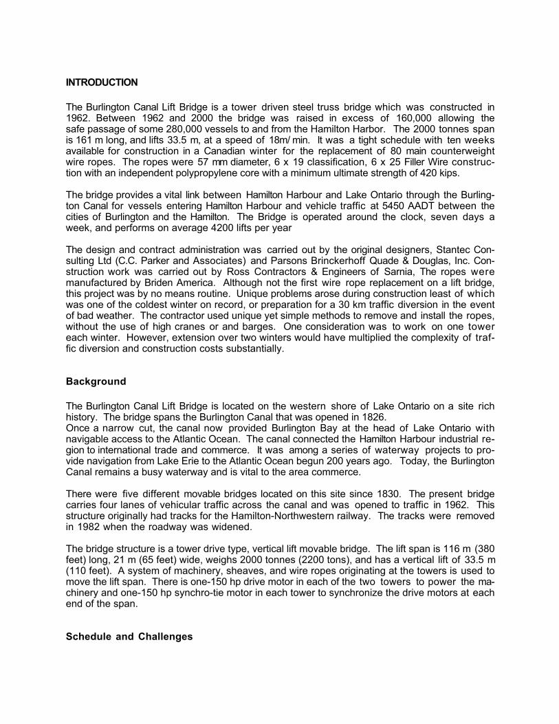
CONSTRUCTION SCHEMEAs part of a feasibility study for the project work, it was anticipated that the removal and installa-tion of the ropes would be accomplished by removal of the sheave shroud and panels from themachinery rooms. Cranes positioned off the approaches or on barges from the canal would thenlift the new ropes up the tower. However after several proposed schemes, the contractor usedvery a simple winch and pulley system to remove the existing and install the new wire ropes. Asimple trolley system that attaches to a socket at one end of the rope was used (See figures 1,2, and 3). To protect the new ropes, each rope was partially covered in plastic tubing. Althoughthe process appeared complicated, the contractor worked very efficiently, increasing the num-ber of ropes installed from about 2 per day to 8 per day there by maintaining the contracts ag-gressive schedule.
ROPE TENSIONINGThe specifications required that the ropes be tensioned following the initial readjustment atone month and six months after the initial tensioning. The specification criterion for acceptance ofthe rope tension in the main counterweight ropes should not differ by more than +- 5% from theaverage rope tension at that corner of the lift span.
Following each round of adjustments the bridge was operated through four lifts and the tensionrechecked. Any deviation in the tension greater than the 5 % criteria would then be adjusted andthe process repeated.
The specifications further required that the rope tension be determined by the use of an acceler-ometer. While this method is more expensive than the vibration method, the use of an acceler-ometer produces data that can easily be verified.
ROPE TESTING
In order to demonstrate the strength of the new rope, the specification required that the ropesbe tested to meet the minimum breaking strength. The testing was conducted as per ASTM931 (Standard Test Method for Tension Testing of Wire Ropes and Strand). The minimumbreaking strength of the specifications was 420k. The test samples broke at a minimum andmaximum of 435k and 445k, respectively.
ROPE LUBRICATION
Lubrication of counterweight ropes is important to the longevity of new or existing ropes.Most lift bridge ropes are maintained by applying lubricants to ropes that are already coveredwith dry lubricants, forming a type of plastic coating on the wire ropes. Rope dressing thatmerely covers the surface of the ropes and does not saturate the rope core will not keep therope in good condition. The lubricant recommended for this project was a “solvent cut back”type lubricant. The lubricant is in liquid state during application and solidifies long after being ap-plied. The use of an automatic lubrication system was considered; however after considerationof several systems, the more traditional method of brushing the lubricant over the wire ropes atthe sheaves was maintained.
SEATING OF LIFT SPANOne of the malfunctions that was expected to be resolved on this project was the properseating of the lift span. Prior to the project, the lift span was not fully seated at all four

corners of the live load shoes. It was anticipated the following could be the cause of theproblem:
1. Unequal tension of the main counterweight ropes2. Bridge imbalance3. Improper adjustment of the controls torque couplings4. Indexing of the operating machinery.5. Improper elevation of the live load shoes
After all the above issues were corrected the bridge was still not fully seated. Aninvestigation of the seating sequence of the lift span indicated that the lift span seats afterreleasing the brakes. An adjustment of the seating sequence resolved this issue.
CONCLUSIONIn spite of the severe cold and time constraints, the project was completed one day ahead ofschedule. The cooperation of the project team was key to the success of this project. Duringthe 10 week schedule the communication and meetings between the client, contractordesigners and fabricators contributed to the success of this project.
Burlington Canal Lift Bridge
New Ropes Attached at Counterweight

BURLINGTON LIFT BRIDGE SPECIFICATIONS
OWNED AND OPERATED BY PUBLIC WORKS & GOVERNMENTSERVICES CANADA1157 BEACH BLVD. HAMILTON ONTARIO L8H 6Z9
BURLINGTON CANAL LIFT BRIDGE, TOWER DRIVEN, STEEL TRUSSLIFTING EQUIPMENT 4 - 150 H.P. WOUND ROTOR MOTORSPOWERED BY 1000 KVA TRANSFORMER AND BACK UP DIESEL GENERATORFIRST LIFT JANUARY 1962
LAT. 43' 17.80N LON. 79' 47.69WELEVATION TOP OF CONCRETE TOWER BASE 254.75 FEET ( 77.647 METERS)CONTROLLED HIGH WATER LEVEL 248.0 FEET ( 75.59 METERS)
DIMENSIONS
LIFT SPAN LENGTH 380 FEET ( 116 METERS )TOWER SPAN LENGTH 32 FEET ( 9.8 METERS )APPROACH SPAN LENGTH 41.4 FEET ( 12.5 METERS )TOTAL LENGTH 526.8 FEET ( 161 METERS )
CLEARANCE
CANAL WIDTH 300 FEET ( 91.5 METERS )ROAD WAY WIDTH 44.5 FEET ( 13.6 METERS )SIDEWALK WIDTH 5 FEET ( 1.5 METERS )ROAD VERTICAL 20 FEET ( 6.1 METERS )ROADWAY TO TOWER FLOOR 160 FEET ( 48.8 METERS )ROADWAY TO SKF BEARINGS 170.5 FEET ( 51.9 METERS )UNDER SOUTH UNDERPASS 11.8 FEET ( 3.5 METERS )PIER TO UNDERSIDE OF SPAN 7.1 FEET ( 2.1 METERS )HEIGHT OF LIFT 110 FEET ( 33.5 METERS )LIFT CLEARANCE 120 FEET ( 36.5 METERS )SEAWAY CLEARANCE IS 116.5 FEET (35.51 METERS )MAXIMUM VERTICAL SPEED 60 FEET PER MINUTE ( 18.2 METERS )
WEIGHTS
SPAN WEIGHT 2200 TONS (1995.84 TONNE)COUNTERWEIGHT, EACH 1093 TONS ( 991.57 TONNE )OUT OF BALANCE LOAD ( SPAN ) 14 TONS ( 12.7 TONNE )