unique sideframe system - thunder tigerjk... · helicopter world champion, designed this helicopter...
TRANSCRIPT

1
Thank you very much for purchasing the Thunder Tiger/Taya "Raptor 60" helicopter. Mr. Taya, the first F3C
Helicopter World Champion, designed this helicopter to be the highest quality model helicopter in the RC
hobby industry. The Raptor 60 is designed for modelers who love building and flying model helicopters.
Only the highest quality materials are used. With the Raptor, the pilot can really appreciate the pleasure of
flying in 3-dimensional space. Its docile handling is ideally suited for beginners. The stable hover and agility
also make it the top choice for contest fliers and extreme 3-D pilots. The Raptor requires the least amount
of assembly of any helicopter kit. The ARF version comes complete with a high performance Thunder Tiger
Pro 70H ring engine and muffler. The helicopter and engine are both manufactured by Thunder Tiger using
the most modern technology and exceed the stringent internationally recognized ISO-9001 manufacturing
standard. We have incorporated all the state-of-the-art technology into designing and making this helicopter.
We believe you will enjoy this model for a long time. We have made no compromise in designing or
manufacturing this model.
Unique Sideframe SystemAluminum side plates are used in conjunction with molded material to construct the main structure. This
design produces a minimum weight with maximum strength. If the sideframes were completely made of
molded material, then to achieve equal strength the plastic would have to be very thick and heavy. Using
molded material at the right place avoids using metal angle brackets or putting compound bends in metal
frames. Slots have been added in the frame design to permit using optional gear ratios to optimize engine
performance to suit any pilot's demand.
Bell-Hiller Mixing Control UnitMain rotor control geometry has been carefully engineered to minimize cross-coupling in collective and cyclic
commands. Blade pitch arms and the Bell-Hiller mixing arms are designed at an angle such that the pushrod
interlinking them are at 90 degrees when the blades are at 0 degree. The pilots will get the symmetrical
cyclic control feel and flybar authority either at +10 or -10 degrees of collective. We designed this system
with the 3-D pilot in mind. We guarantee you this whole design philosophy provides a strong and accurate
control mechanism.
Shaft Drive Tail RotorThe Raptor 60 is designed with a constant drive tail rotor system to permit full tail rotor control during
autorotations. Backward autos, pirouette autos and 180 autos are all within your reach now. It has the same
aluminum torque tube system as the Thunder Tiger/Taya Imperio helicopter. This allows obtaining the
maximum performance from any modern high gain gyros.
3D CAD DesignWe used modern 3D Computer Aided Design to design and manufacture the Raptor 60. Our high-tech CAD
program allows simulation of all the moving part to ensure non-interference. The analysis automatically
analyze the weight, the mass distribution, and inertia to help us pursue a design that will provide the high
level of maneuverability needed for all-out 3-D aerobatics.
Instruction
2
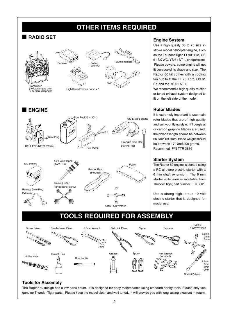
OTHER ITEMS REQUIRED
Glow Plug Wrench
12V Battery1.5V Glow starter(1.2V~1.5V)
Rubber Band
(Included)
Foam
Remote Glow Plug
Extension
Training Gear
(for beginners only)
Receiver
Transmitter(helicopter type only 6 or more channels)
High Speed/Torque Servo x 5
Battery1200mAh
Switch harness
Gyro
RADIO SET
ENGINE
Extended 6mm Hex
Starting ToolFuel Pump
HELI ENGINE(60-70size)
Glow Fuel(15%-30%)
Glow Plug
12V Electric starter
TOOLS REQUIRED FOR ASSEMBLY
Socket Drivers
Hex WrenchGrease
Blue Loctite
Instant GlueHobby Knife
Metric4-way WrenchScissorsNipper5.5mm WrenchNeedle Nose PliersScrew Driver
7mm
5.5mm7mm8mm
5.5mm7mm8mm
10mm
Epoxy
Ball Link Pliers
Tools for AssemblyThe Raptor 60 design has a low parts count. It is designed for easy maintenance using standard hobby tools. Please only use
genuine Thunder Tiger parts. Please keep the model clean and well tuned. It will provide you with long lasting pleasure in return.
Engine SystemUse a high quality 60 to 75 size 2-
stroke model helicopter engine, such
as the Thunder Tiger TT70H Pro, OS
61 SX WC, YS 61 ST II, or equivalent.
Please beware, some engine will not
fit because of its shape and size. The
Raptor 60 kit comes with a cooling
fan hub to fit the TT 70H pro, OS 61
SX and the YS 61 ST II.
We recommend a high quality muffler
or tuned exhaust system designed to
fit on the left side of the model.
Rotor BladesIt is extremely important to use main
rotor blades that are of high quality
and suit your flying style. If fiberglass
or carbon graphite blades are used,
their blade length should be between
660 and 690 mm. Blade weight should
be between 170 and 200 grams.
Recommed P/N TTR 3836
Starter SystemThe Raptor 60 engine is started using
a RC airplane electric starter with a
6 mm shaft extension. The 6 mm
starter extension is available from
Thunder Tiger, part number TTR 3801.
Use a strong high torque 12 volt
electric starter that is designed for
model use.
(Included)
3
Repair and replacement PartsPurchase replacement parts from the hobby shop where you have purchased the Raptor 60. Please contact the Thunder
Tiger distributor in your country, and the distributor can tell you where to obtain the parts. For example, in the U.S, all
Thunder Tiger products are distributed by Ace Hobby Distributors. On the web site www.acehobby.com, there is a list
of all the hobby shops in the USA that can special order any Thunder Tiger parts from Ace for you. Technical questions
on the Raptor will be answered quickly sending an email to [email protected] or call Technical Support at 949-
833-7498. In Europe, Asia and Australia, please contact the distributor in your country.
WarningsTo ensure safety, please read the instruction manual thoroughly before assembly. Radio control helicopters are
sophisticated equipment, and not toys. Radio control model helicopters are capable of causing serious bodily injury if
not properly assembled or operated. The manufacturer and distributors assume no liability for damages that could
occur from the assembly or use of this product. This product is designed for hobby use only. Operating model Helicopters
requires diligence and skill. It is best to seek help and guidance from other accomplished model helicopter pilots to
ensure quick and successful learning. It is strongly recommended to join the appropriate radio control modeling governing
society in your country. For example, in the United States, it is strongly encouraged to join the Academy of Model
Aeronautics. AMA is a nonprofit organization that provides members in the United States with liability insurance and
monthly modeling magazines. For further information or to find a model
helicopter club that's nearest to you, please contact AMA at:
Academy of Model aeronautics
515 East Memorial Drive
Muncie, IN 47302
USA
(317) 287-1256
We also encourage start subscribing to different radio control helicopter magazines to learn about RC flying events,
new flying techniques, safety procedures, and hints. Rotory Modeler is a bi-monthly and Model Helicopter Techniques
is a quarterly newsletter published in the USA. Model Helicopter World is a month magazine published by Traplet
Publication in England and sold worldwide. Rotor is a monthly German magazine. Helico is a Swiss quarterly magazine.
Attention We are unable to accept replacement or return of this model after it has been used or assembly has begun.
It is legally prohibited to duplicate or reprint this manual in any format without a written permission from the manufacturer.
The manufacturer has the right to make changes to this model or instruction without notice.
We have done our best to ensure the accuracy of information in this manual. If you are aware of any mistake, we
welcome you to notify us.
We will not accept any responsibility for any accident, breakdown, fault or trouble caused by improper usage of this
model. Please thoroughly inspect your model and range check the radio before flight. Please keep the model in its
best condition in order to enjoy it.
This model does not include all the items necessary for flying. It still needs a helicopter radio control system, a 60-
size 2-stroke engine, and a muffler.
It is difficult for beginners to fly RC helicopters by themselves. It is highly recommended that beginners seek the help
of experienced RC helicopter pilots. We recommend beginners start with an inexpensive model such as the Thunder
Tiger Raptor 30 that is also designed by Mr. Taya.
RC helicopters are not toys. The manufacturer does not assume the liability for any property or bodily damage caused
by the model or the operator.
4
In order to enjoy a safe and enjoyable experience, please study the manual carefully and completely understand
the helicopter structure and operation before the first flight.
Read the warnings to avoid injuries to you and others.
WARNING – The following could cause heavy injury or death if used incorrectly.
Keep the model away from other people or animal when starting the engine.
Do not fly any model helicopter near or above people or cars. Models can sometimes go out of control
due to pilot or mechanical failure.
WARNING – The following could also cause serious injury or death if not careful.
Take precaution with model fuel. Model engine glow fuel is highly flammable.
Please check the model carefully before each flight. Make sure that nothing has loosened up or come
apart.
Make sure everything moves freely without binding or excessive friction.
Do not operate the model in rain, snow, thunderstorm, or adverse weather.
WARNING – The following could also cause serious injury or death if not careful.
Please check to make sure that your radio frequency is not used before flight. If someone else is
flying on the same frequency as your radio, then do not turn on your transmitter. Otherwise, you
can cause a crash and even bodily and property damages.
Please monitor the fuel level during flight so you do not run out of fuel during flight.
Before each flight, please check that all servos and controls move properly.
Do not modify any parts or use other than genuine Thunder Tiger parts.
Do not fly in places that are forbidden by law.
Use Loctite on screws that do not use a locknut.
When operating the model, please beware that no loose cloth or jewelry can get entangled in the
model helicopter.
Make sure the transmitter and receiver switches are on before starting the engine.
Do not touch the engine or the muffler immediately after running the engine because they are very
hot and can cause burn.
Do not use this model for anything other than hobby.
WARNING – The following describes damage that can happen to the model.
Do not leave the model in a car for a long time. The heat in the summer or the cold in the winter and
the humidity can cause damage to the model.
Be careful and watch the sharp edges and corners on the model.
5
MAIN FRAME ASSEMBLY
1
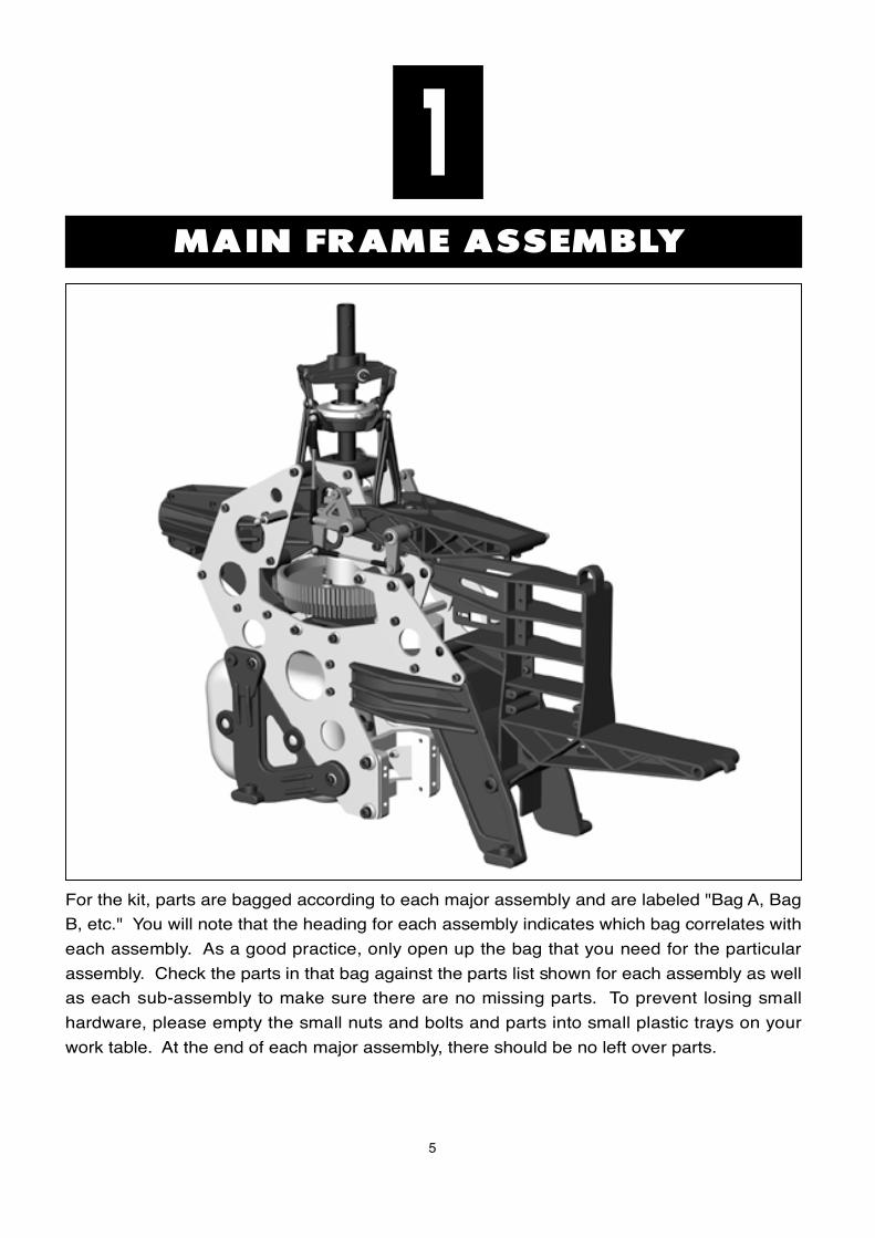
For the kit, parts are bagged according to each major assembly and are labeled "Bag A, Bag
B, etc." You will note that the heading for each assembly indicates which bag correlates with
each assembly. As a good practice, only open up the bag that you need for the particular
assembly. Check the parts in that bag against the parts list shown for each assembly as well
as each sub-assembly to make sure there are no missing parts. To prevent losing small
hardware, please empty the small nuts and bolts and parts into small plastic trays on your
work table. At the end of each major assembly, there should be no left over parts.
6
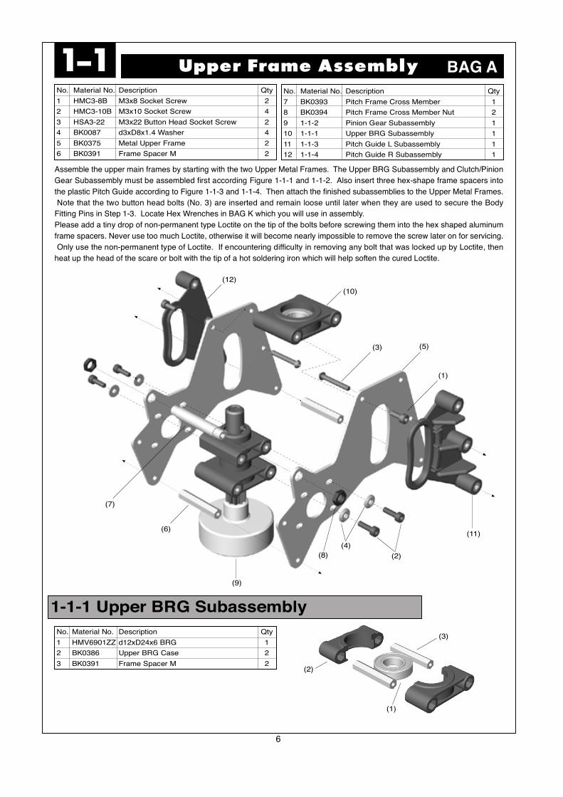
Upper Frame Assembly1-1No. Material No. Description Qty
1 HMC3-8B M3x8 Socket Screw 2
2 HMC3-10B M3x10 Socket Screw 4
3 HSA3-22 M3x22 Button Head Socket Screw 2
4 BK0087 d3xD8x1.4 Washer 4
5 BK0375 Metal Upper Frame 2
6 BK0391 Frame Spacer M 2
No. Material No. Description Qty
7 BK0393 Pitch Frame Cross Member 1
8 BK0394 Pitch Frame Cross Member Nut 2
9 1-1-2 Pinion Gear Subassembly 1
10 1-1-1 Upper BRG Subassembly 1
11 1-1-3 Pitch Guide L Subassembly 1
12 1-1-4 Pitch Guide R Subassembly 1
BAG A
(2)
(3)
(1)
No. Material No. Description Qty
1 HMV6901ZZ d12xD24x6 BRG 1
2 BK0386 Upper BRG Case 2
3 BK0391 Frame Spacer M 2
1-1-1 Upper BRG Subassembly
Assemble the upper main frames by starting with the two Upper Metal Frames. The Upper BRG Subassembly and Clutch/Pinion
Gear Subassembly must be assembled first according Figure 1-1-1 and 1-1-2. Also insert three hex-shape frame spacers into
the plastic Pitch Guide according to Figure 1-1-3 and 1-1-4. Then attach the finished subassemblies to the Upper Metal Frames.
Note that the two button head bolts (No. 3) are inserted and remain loose until later when they are used to secure the Body
Fitting Pins in Step 1-3. Locate Hex Wrenches in BAG K which you will use in assembly.
Please add a tiny drop of non-permanent type Loctite on the tip of the bolts before screwing them into the hex shaped aluminum
frame spacers. Never use too much Loctite, otherwise it will become nearly impossible to remove the screw later on for servicing.
Only use the non-permanent type of Loctite. If encountering difficulty in removing any bolt that was locked up by Loctite, then
heat up the head of the scare or bolt with the tip of a hot soldering iron which will help soften the cured Loctite.
(12)
(10)
(3) (5)
(1)
(11)
(4)
(8)
(9)
(6)
(7)
(2)
7
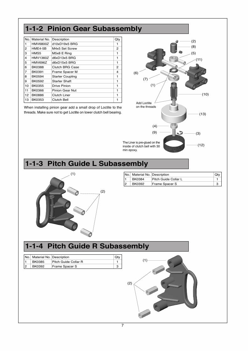
1-1-2 Pinion Gear Subassembly
1-1-3 Pitch Guide L Subassembly
1-1-4 Pitch Guide R Subassembly
No. Material No. Description Qty
1 BK0384 Pitch Guide Collar L 1
2 BK0392 Frame Spacer S 3
No. Material No. Description Qty
1 BK0385 Pitch Guide Collar R 1
2 BK0392 Frame Spacer S 3
(2)
(5)
(11)
(10)
(13)
(3)
(12)
(9)
(4)
(1)
(7)
(6)
The Liner is pre-glued on the
inside of clutch bell with 30min epoxy.
(1)
(2)
(1)
(2)
No. Material No. Description Qty
1 HMV6800Z d10xD19x5 BRG 1
2 HME4-5B M4x5 Set Screw 2
3 HMS5 M5x8 E Ring 1
4 HMV1360Z d6xD13x5 BRG 1
5 HMV696Z d6xD15x5 BRG 1
6 BK0388 Clutch BRG Case 2
7 BK0391 Frame Spacer M 4
8 BK0594 Starter Coupling 1
9 BK0592 Starter Shaft 1
10 BK0355 Drive Pinion 1
11 BK0366 Pinion Gear Nut 1
12 BK0886 Clutch Liner 1
13 BK0353 Clutch Bell 1
(8)
When installing pinion gear add a small drop of Loctite to the
threads. Make sure not to get Loctite on lower clutch bell bearing.
Add Loctiteon the threads
8
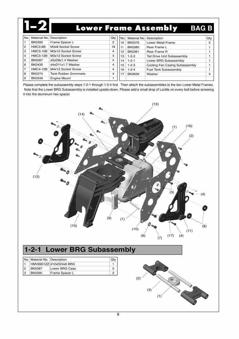
No. Material No. Description Qty
1 BK0390 Frame Spacer L 2
2 HMC3-8B M3x8 Socket Screw 18
3 HMC3-10B M3x10 Socket Screw 4
4 HMC3-12B M3x12 Socket Screw 4
5 BK0087 d3xD8x1.4 Washer 4
6 BK0435 d4xD11x1.7 Washer 4
7 HMC4-12B M4x12 Socket Screw 4
8 BK0274 Tank Rubber Grommets 4
9 BK0349 Engine Mount 1
Lower Frame Assembly1-2
(13)
(1) (16)
(2)
(8)
(11)
(17)(7)
(6)
(10)
(1)(9)
(15)
(12)
No. Material No. Description Qty
10 BK0376 Lower Metal Frame 2
11 BK0380 Rear Frame L 1
12 BK0381 Rear Frame R 1
13 1-2-2 Tail Drive Unit Subassembly 1
14 1-2-1 Lower BRG Subassembly 1
15 1-2-3 Cooling Fan Casing Subassembly 1
16 1-2-4 Fuel Tank Subassembly 1
17 BK0629 Washer 4
BAG B
(14)
(3)
(4)
(4)
Please complete the subassembly steps 1-2-1 through 1-2-4 first. Then attach the subassemblies to the two Lower Metal Frames.
Note that the Lower BRG Subassembly is installed upside-down. Please add a small drop of Loctite on every bolt before screwing
it into the aluminum hex spacer.
(3)
(2)
(1)
1-2-1 Lower BRG Subassembly
No. Material No. Description Qty
1 HMV6901ZZ d12xD24x6 BRG 1
2 BK0387 Lower BRG Case 2
3 BK0390 Frame Spacer L 2
9
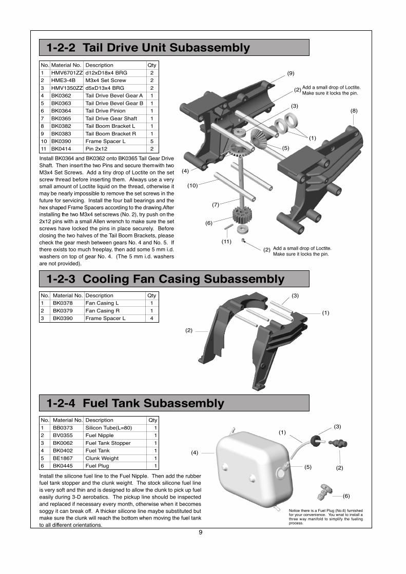
1-2-2 Tail Drive Unit Subassembly
1-2-3 Cooling Fan Casing Subassembly
No. Material No. Description Qty
1 BK0378 Fan Casing L 1
2 BK0379 Fan Casing R 1
3 BK0390 Frame Spacer L 4
(9)
(3)
(2)
(1)
(5)
(8)
(11)
(6)
(7)
(10)
(4)
No. Material No. Description Qty
1 HMV6701ZZ d12xD18x4 BRG 2
2 HME3-4B M3x4 Set Screw 2
3 HMV1350ZZ d5xD13x4 BRG 2
4 BK0362 Tail Drive Bevel Gear A 1
5 BK0363 Tail Drive Bevel Gear B 1
6 BK0364 Tail Drive Pinion 1
7 BK0365 Tail Drive Gear Shaft 1
8 BK0382 Tail Boom Bracket L 1
9 BK0383 Tail Boom Bracket R 1
10 BK0390 Frame Spacer L 5
11 BK0414 Pin 2x12 2
Install BK0364 and BK0362 onto BK0365 Tail Gear Drive
Shaft. Then insert the two Pins and secure them with two
M3x4 Set Screws. Add a tiny drop of Loctite on the set
screw thread before inserting them. Always use a very
small amount of Loctite liquid on the thread, otherwise it
may be nearly impossible to remove the set screws in the
future for servicing. Install the four ball bearings and the
hex shaped Frame Spacers according to the drawing.After
installing the two M3x4 set screws (No. 2), try push on the
2x12 pins with a small Allen wrench to make sure the set
screws have locked the pins in place securely. Before
closing the two halves of the Tail Boom Brackets, please
check the gear mesh between gears No. 4 and No. 5. If
there exists too much freeplay, then add some 5 mm i.d.
washers on top of gear No. 4. (The 5 mm i.d. washers
are not provided).
Install the silicone fuel line to the Fuel Nipple. Then add the rubber
fuel tank stopper and the clunk weight. The stock silicone fuel line
is very soft and thin and is designed to allow the clunk to pick up fuel
easily during 3-D aerobatics. The pickup line should be inspected
and replaced if necessary every month, otherwise when it becomes
soggy it can break off. A thicker silicone line maybe substituted but
make sure the clunk will reach the bottom when moving the fuel tank
to all different orientations.
(1)
(2)
(3)
1-2-4 Fuel Tank Subassembly
No. Material No. Description Qty
1 BB0373 Silicon Tube(L=80) 1
2 BV0355 Fuel Nipple 1
3 BK0062 Fuel Tank Stopper 1
4 BK0402 Fuel Tank 1
5 BE1867 Clunk Weight 1
6 BK0445 Fuel Plug 1
(1)
(2)
(3)
(5)
(4)
(6)
Notice there is a Fuel Plug (No.6) furnishedfor your convenience. You wnat to install athree way manifold to simplify the fuelingprocess.
Add a small drop of Loctite.Make sure it locks the pin.
(2)
Add a small drop of Loctite.Make sure it locks the pin.

10
1-3-1 Rod Guide Collar Subassembly
No. Material No. Description Qty
1 HMC3-25B M3x25 Socket Screw 10
2 BK0087 d3xD8x1.4 Washer 4
3 BK0103 Body Fitting Pin 2
4 BK0392 Frame Spacer S 2
5 1-3-1 Rod Guide Collar Subassembly 2
6 1-1 Upper Frame Assembly 1
7 1-2 Lower Frame Assembly 1
No. Material No. Description Qty
1 BK0389 Rod Guide Collar 1
2 BK0392 Frame Spacer S 2
Main Frame Assembly1-3
(1)
(3)
(2)
(5)
(4)
(2)
(1)
BAG C
(6)
(7)
Insert two hex Frame Spacers S into
the plastic Rod Guide Collars (1-3-1).
Then join the Upper Frame Assembly
to the Lower Frame Assembly according
to the drawing. Do not forget to install
the four taper washers (2) under the
bolts for the Rod Guide Collars. The
two Body Pins (BK0103) will be used
to secure the canopy in the future. Add
Loctite on all bolts and inside BK0103
threaded hole.
11
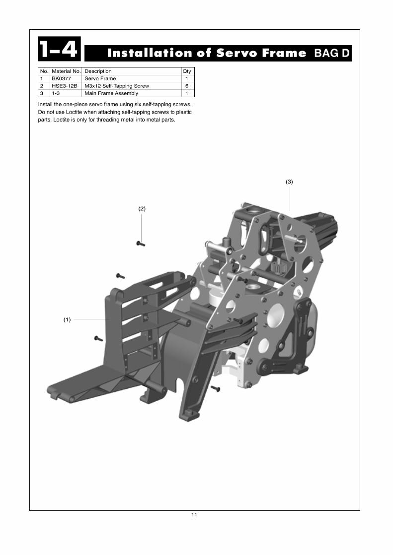
No. Material No. Description Qty
1 BK0377 Servo Frame 1
2 HSE3-12B M3x12 Self-Tapping Screw 6
3 1-3 Main Frame Assembly 1
Installation of Servo Frame1-4
(1)
(2)
(3)
BAG D
Install the one-piece servo frame using six self-tapping screws.
Do not use Loctite when attaching self-tapping screws to plastic
parts. Loctite is only for threading metal into metal parts.
12
No. Material No. Description Qty
1 BK0093 2x46 Link Rod 1
2 HMC3-10B M3x10 Socket Screw 1
3 HMJ3-20N M3x20 Self-Tapping Screw 4
4 HMC3-25B M3x25 Socket Screw 1
5 BK0088 d3xD5x0.5 Washer 1
6 BK0020 Elevator Arm Shaft 1
7 1-5-1 Aileron Lever L Subassembly 1
8 1-5-1 Aileron Lever R Subassembly 1
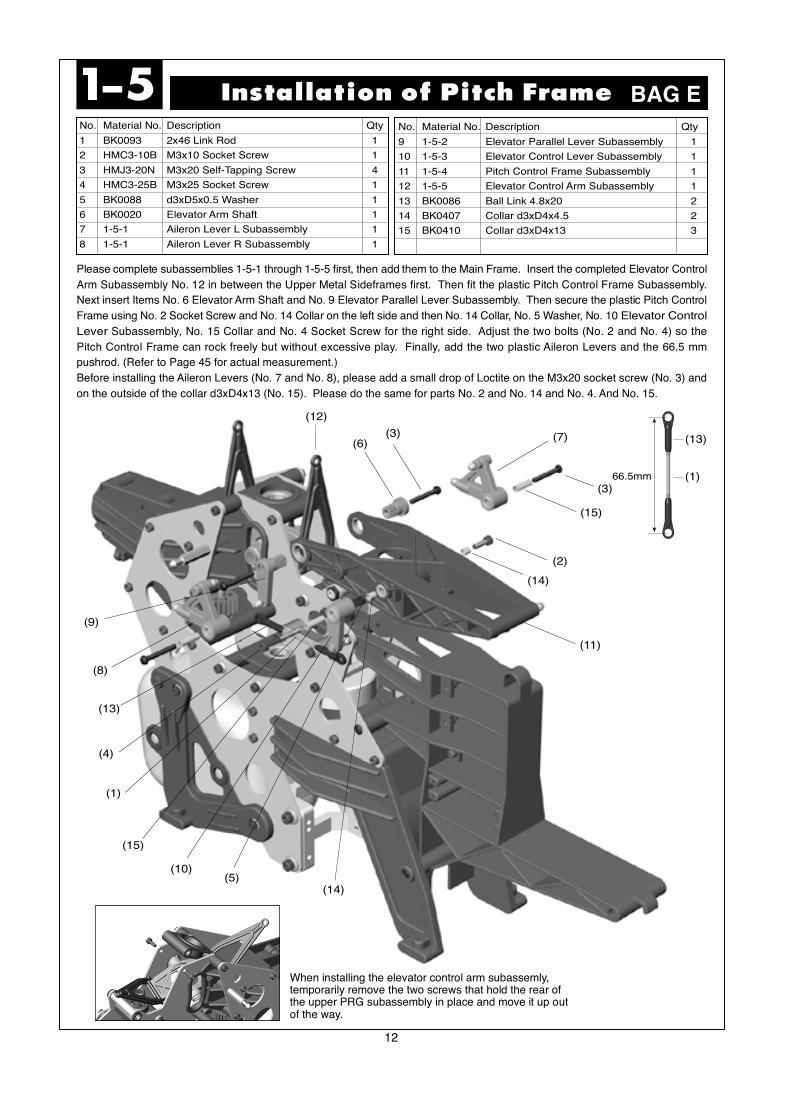
Please complete subassemblies 1-5-1 through 1-5-5 first, then add them to the Main Frame. Insert the completed Elevator Control
Arm Subassembly No. 12 in between the Upper Metal Sideframes first. Then fit the plastic Pitch Control Frame Subassembly.
Next insert Items No. 6 Elevator Arm Shaft and No. 9 Elevator Parallel Lever Subassembly. Then secure the plastic Pitch Control
Frame using No. 2 Socket Screw and No. 14 Collar on the left side and then No. 14 Collar, No. 5 Washer, No. 10 Elevator Control
Lever Subassembly, No. 15 Collar and No. 4 Socket Screw for the right side. Adjust the two bolts (No. 2 and No. 4) so the
Pitch Control Frame can rock freely but without excessive play. Finally, add the two plastic Aileron Levers and the 66.5 mm
pushrod. (Refer to Page 45 for actual measurement.)
Before installing the Aileron Levers (No. 7 and No. 8), please add a small drop of Loctite on the M3x20 socket screw (No. 3) and
on the outside of the collar d3xD4x13 (No. 15). Please do the same for parts No. 2 and No. 14 and No. 4. And No. 15.
Installation of Pitch Frame1-5No. Material No. Description Qty
9 1-5-2 Elevator Parallel Lever Subassembly 1
10 1-5-3 Elevator Control Lever Subassembly 1
11 1-5-4 Pitch Control Frame Subassembly 1
12 1-5-5 Elevator Control Arm Subassembly 1
13 BK0086 Ball Link 4.8x20 2
14 BK0407 Collar d3xD4x4.5 2
15 BK0410 Collar d3xD4x13 3
BAG E
(11)
(14)
(2)
(15)
(7)(3)(6)
(12)
(9)
(8)
(13)
(4)
(1)
(15)
(10)(5)
(14)
(3)66.5mm
(13)
(1)
When installing the elevator control arm subassemly,temporarily remove the two screws that hold the rear ofthe upper PRG subassembly in place and move it up outof the way.

13
1-5-1 Aileron Lever Subassembly
1-5-2 Elevator Parallel Lever Subassembly
1-5-3 Elevator Control Lever Subassembly
No. Material No. Description Qty
1 HMJ2-10N M2x10 Self-Tapping Screw 2
2 HMV840ZZ d4xD8x3 BRG 2
3 BK0340 Aileron Control Arm 1
4 BK0075 Link Ball 4.8 2
No. Material No. Description Qty
1 HMJ2-10N M2x10 Self-Tapping Screw 2
2 HMV840ZZ d4xD8x3 BRG 2
3 BK0340 Aileron Control Arm 1
4 BK0075 Link Ball 4.8 2
No. Material No. Description Qty
1 HMJ2-8N M2x8 Self-Tapping Screw 1
2 BK0337 Elevator Arm Parallel Lever 1
3 BK0075 Link Ball 4.8 1
No. Material No. Description Qty
1 HMJ2-14N M2x14 Self-Tapping Screw 1
2 HMV840ZZ d4xD8x3 BRG 2
3 BK0338 Elevator Control Lever 1
4 BK0075 Link Ball 4.8 2
(2)
(1)
(4)
(3)
(1)(4)
(2)
(3)
(2)
(3)
(1)
(1)
(4)
(2)(3)
(L)(R)
Add a tiny drop of thick CA glue at the tip of the M2x10
self-tapping screw (No. 1) before screwing it into the
Aileron Levers.
(3)
(1)
(2)
14
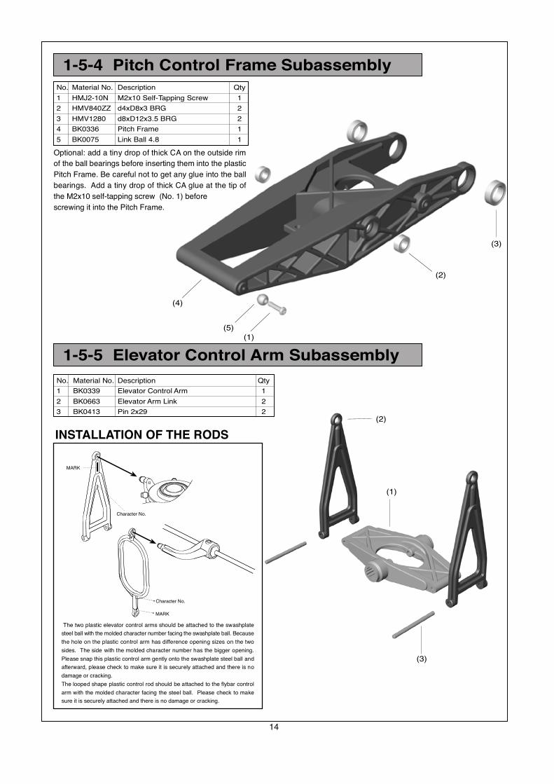
1-5-4 Pitch Control Frame Subassembly
1-5-5 Elevator Control Arm Subassembly
No. Material No. Description Qty
1 HMJ2-10N M2x10 Self-Tapping Screw 1
2 HMV840ZZ d4xD8x3 BRG 2
3 HMV1280 d8xD12x3.5 BRG 2
4 BK0336 Pitch Frame 1
5 BK0075 Link Ball 4.8 1
No. Material No. Description Qty
1 BK0339 Elevator Control Arm 1
2 BK0663 Elevator Arm Link 2
3 BK0413 Pin 2x29 2
The two plastic elevator control arms should be attached to the swashplate
steel ball with the molded character number facing the swashplate ball. Because
the hole on the plastic control arm has difference opening sizes on the two
sides. The side with the molded character number has the bigger opening.
Please snap this plastic control arm gently onto the swashplate steel ball and
afterward, please check to make sure it is securely attached and there is no
damage or cracking.
The looped shape plastic control rod should be attached to the flybar control
arm with the molded character facing the steel ball. Please check to make
sure it is securely attached and there is no damage or cracking.
INSTALLATION OF THE RODS
2
2
Character No.
Character No.
MARK
MARK
Optional: add a tiny drop of thick CA on the outside rim
of the ball bearings before inserting them into the plastic
Pitch Frame. Be careful not to get any glue into the ball
bearings. Add a tiny drop of thick CA glue at the tip of
the M2x10 self-tapping screw (No. 1) before
screwing it into the Pitch Frame.
(1)
(5)
(4)
(2)
(3)

15
No. Material No. Description Qty
1 BK0093 2x46 Link Rod 2
2 HMC3-6B M3x6 Socket Screw 2
3 HMM4B M4 Locknut 1
4 BK0617 M4 Bolt 1
5 BK0360 Main Shaft 1
Installation of Main Shaft1-6
(3)
(9)
(4)
(6)
(2)
(1)
(10)(8)
(7)
(5)
No. Material No. Description Qty
6 BK0234 Lock Ring 1
7 1-6-1 Wash Out Subassembly 1
8 1-6-2 Swash Plate Subassembly 1
9 1-6-3 Main Gear Subassembly 1
10 BK0086 Ball Link 4.8x20 4
BAG F
Assemble the constant drive Main Gear Subassembly according to Figure 1-6-3 first. Then build-up the Wash Out Subassembly
and Swash Plate Subassembly according to 1-6-1 and 1-6-2. Insert the No. 5 Main Shaft into the bearings and then add the
No. 6 Lock Ring and the slide through the Main Gear Subassembly. Do not over tighten the M4x25 bolt, otherwise the BK0359
Shaft will be distorted and prevent the Autorotation Clutch from turning freely. Add the M3x6 Socket Screw to the Locking Ring.
Slide the Locking Ring all the way up until the rotor shaft has no up and down play, then tighten the M3x6 Socket Screw.
66.5mm
(10)
(1)
16
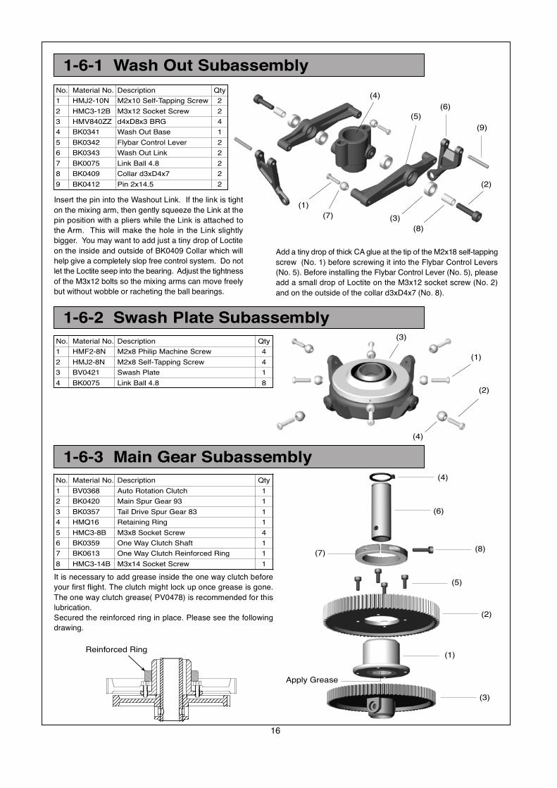
1-6-1 Wash Out Subassembly
No. Material No. Description Qty
1 HMJ2-10N M2x10 Self-Tapping Screw 2
2 HMC3-12B M3x12 Socket Screw 2
3 HMV840ZZ d4xD8x3 BRG 4
4 BK0341 Wash Out Base 1
5 BK0342 Flybar Control Lever 2
6 BK0343 Wash Out Link 2
7 BK0075 Link Ball 4.8 2
8 BK0409 Collar d3xD4x7 2
9 BK0412 Pin 2x14.5 2
1-6-3 Main Gear Subassembly
No. Material No. Description Qty
1 BV0368 Auto Rotation Clutch 1
2 BK0420 Main Spur Gear 93 1
3 BK0357 Tail Drive Spur Gear 83 1
4 HMQ16 Retaining Ring 1
5 HMC3-8B M3x8 Socket Screw 4
6 BK0359 One Way Clutch Shaft 1
7 BK0613 One Way Clutch Reinforced Ring 1
8 HMC3-14B M3x14 Socket Screw 1
Reinforced Ring(1)
(3)
(4)
(6)
(5)
(2)
(2)
(1)
(4)
(3)
(1)
(7) (3)
(8)
(2)
(9)
(6)
(5)
(4)
Insert the pin into the Washout Link. If the link is tight
on the mixing arm, then gently squeeze the Link at the
pin position with a pliers while the Link is attached to
the Arm. This will make the hole in the Link slightly
bigger. You may want to add just a tiny drop of Loctite
on the inside and outside of BK0409 Collar which will
help give a completely slop free control system. Do not
let the Loctite seep into the bearing. Adjust the tightness
of the M3x12 bolts so the mixing arms can move freely
but without wobble or racheting the ball bearings.
No. Material No. Description Qty
1 HMF2-8N M2x8 Philip Machine Screw 4
2 HMJ2-8N M2x8 Self-Tapping Screw 4
3 BV0421 Swash Plate 1
4 BK0075 Link Ball 4.8 8
1-6-2 Swash Plate Subassembly
Apply Grease
Add a tiny drop of thick CA glue at the tip of the M2x18 self-tapping
screw (No. 1) before screwing it into the Flybar Control Levers
(No. 5). Before installing the Flybar Control Lever (No. 5), please
add a small drop of Loctite on the M3x12 socket screw (No. 2)
and on the outside of the collar d3xD4x7 (No. 8).
(8)(7)
It is necessary to add grease inside the one way clutch before
your first flight. The clutch might lock up once grease is gone.
The one way clutch grease( PV0478) is recommended for this
lubrication.
Secured the reinforced ring in place. Please see the following
drawing.
17
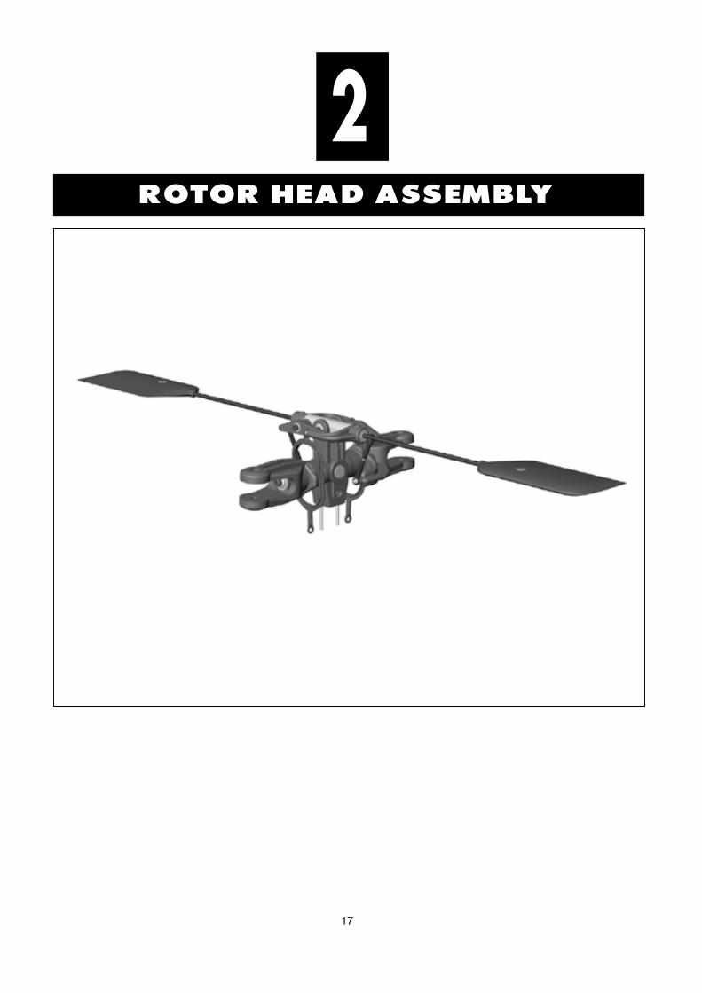
ROTOR HEAD ASSEMBLY
2
18
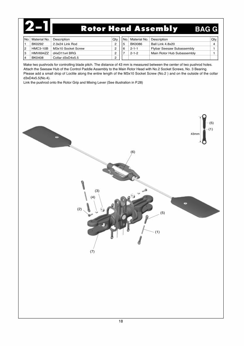
No. Material No. Description Qty.
1 BK0292 2.3x24 Link Rod 2
2 HMC3-10B M3x10 Socket Screw 2
3 HMV694ZZ d4xD11x4 BRG 2
4 BK0408 Collar d3xD4x5.5 2
No. Material No. Description Qty.
5 BK0086 Ball Link 4.8x20 4
6 2-1-1 Flybar Seesaw Subassembly 1
7 2-1-2 Main Rotor Hub Subassembly 1
Rotor Head Assembly2-1 BAG G
Make two pushrods for controlling blade pitch. The distance of 43 mm is measured between the center of two pushrod holes.
Attach the Seesaw Hub of the Control Paddle Assembly to the Main Rotor Head with No.2 Socket Screws, No. 3 Bearing.
Please add a small drop of Loctite along the entire length of the M3x10 Socket Screw (No.2 ) and on the outside of the collar
d3xD4x5.5(No.4).
Link the pushrod onto the Rotor Grip and Mixing Lever (See illustration in P.28)
43mm
(5)
(1)
(1)
(5)
(6)
(3)
(4)
(2)
(7)
19
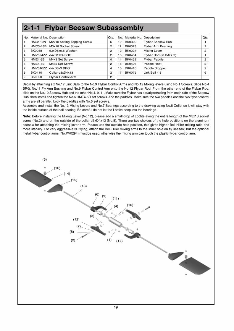
2-1-1 Flybar Seesaw Subassembly BAG G
Begin by attaching six No.17 Link Balls to the No.9 Flybar Control Arms and No.12 Mixing levers using No.1 Screws. Slide No.4
BRG, No.11 Fly Arm Bushing and No.9 Flybar Control Arm onto the No.12 Flybar Rod. From the other end of the Flybar Rod,
slide on the No.10 Seesaw Hub and the other No.4, 9, 11. Make sure the Flybar has equal protruding from each side of the Seesaw
Hub, then install and tighten the No.6 HME4-5B set screws. Add the paddles. Make sure the two paddles and the two flybar control
arms are all parallel. Lock the paddles with No.5 set screws.
Assemble and install the No.12 Mixing Levers and No.7 Bearings according to the drawing using No.8 Collar so it will stay with
the inside surface of the ball bearing. Be careful do not let the Loctite seep into the bearings.
Note: Before installing the Mixing Lever (No.12), please add a small drop of Loctite along the entire length of the M3x18 socket
screw (No.2) and on the outside of the collar d3xD4x13 (No.8). There are two choices of the hole positions on the aluminum
seesaw for attaching the mixing lever arm. Please use the outside hole position, this gives higher Bell-Hiller mixing ratio and
more stability. For very aggressive 3D flying, attach the Bell-Hiller mixing arms to the inner hole on fly seesaw, but the optional
metal flybar control arms (No.PV0294) must be used, otherwise the mixing arm can touch the plastic flybar control arm.
(5)
(16)
(14)
(15)
(13)
(6)(9)
(11)
(4) (10)
(2)
(8)
(7)
(12)(3)
(1) (17)
No. Material No. Description Qty.
10 BK0322 Flybar Seesaw Hub 1
11 BK0323 Flybar Arm Bushing 2
12 BK0324 Mixing Lever 2
13 BK0434 Flybar Rod (In BAG O) 1
14 BK0432 Flybar Paddle 2
15 BK0406 Paddle Root 2
16 BK0416 Paddle Stopper 2
17 BK0075 Link Ball 4.8 6
No. Material No. Description Qty.
1 HMJ2-10N M2x10 Selfing-Tapping Screw 6
2 HMC3-18B M3x18 Socket Screw 2
3 BK0088 d3xD5x0.5 Washer 2
4 HMV694ZZ d4xD11x4 BRG 2
5 HME4-3B M4x3 Set Screw 4
6 HME4-5B M4x5 Set Screw 2
7 HMV840ZZ d4xD8x3 BRG 4
8 BK0410 Collar d3xD4x13 2
9 BK0320 Flybar Control Arm 2
20
2-1-2 Main Rotor Hub Subassembly
(11)
(7)
(10)
(12)
(9)
(4)
(6)(4)
(8)
(5)
(3)
(2)
(13)
(1)
(14)
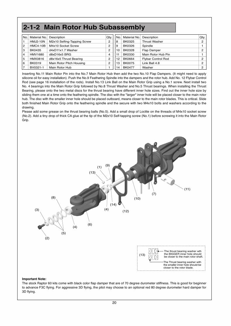
Inserting No.11 Main Rotor Pin into the No.7 Main Rotor Hub then add the two No.10 Flap Dampers. (It might need to apply
silicone oil for easy installation). Push the No.9 Feathering Spindle into the dampers and the rotor hub. Add No. 12 Flybar Control
Rod (see page 16 installation of the rods). Install No.13 Link Ball on the Main Rotor Grip using a No.1 screw. Next install two
No. 4 bearings into the Main Rotor Grip followed by No.8 Thrust Washer and No.5 Thrust bearings. When installing the Thrust
Bearing, please onto the two metal discs for the thrust bearing have different inner hole sizes. Find out the inner hole size by
sliding them one at a time onto the feathering spindle. The disc with the "larger" inner hole will be placed closer to the main rotor
hub. The disc with the smaller inner hole should be placed outboard, means closer to the main rotor blades. This is critical. Slide
both finished Main Rotor Grip onto the feathering spindle and the secure with two M4x10 bolts and washers according to the
drawing.
Please add some grease on the thrust bearing balls (No.5). Add a small drop of Loctite on the threads of M4x10 socket screw
(No.2). Add a tiny drop of thick CA glue at the tip of the M2x10 Self-tapping screw (No.1) before screwing it into the Main Rotor
Grip.
Important Note:
The stock Raptor 60 kits come with black color flap damper that are of 70 degree durometer stiffness. This is good for beginner
to advance F3C flying. For aggressive 3D flying, the pilot may choose to an optional red 80 degree durometer hard damper for
3D flying.
No. Material No. Description Qty.
8 BK0325 Thrust Washer 2
9 BK0326 Spindle 1
10 BK0328 Flap Damper 2
11 BK0330 Main Rotor Hub Pin 1
12 BK0664 Flybar Control Rod 2
13 BK0075 Link Ball 4.8 2
14 BK0477 Washer 2
No. Material No. Description Qty.
1 HMJ2-10N M2x10 Selfing-Tapping Screw 2
2 HMC4-10B M4x10 Socket Screw 2
3 BK0435 d4xD11x1.7 Washer 2
4 HMV1680 d8xD16x5 BRG 4
5 HMX0816 d8x16x5 Thrust Bearing 2
6 BK0319 Main Rotor Pitch Housing 2
7 BV0321-1 Main Rotor Hub 1
The Thrust bearing washer withthe smaller inner hole should becloser to the rotor blade.
The thrust bearing washer wththe BIGGER inner hole shouldbe closer to the main rotor shaft.
(13)
21
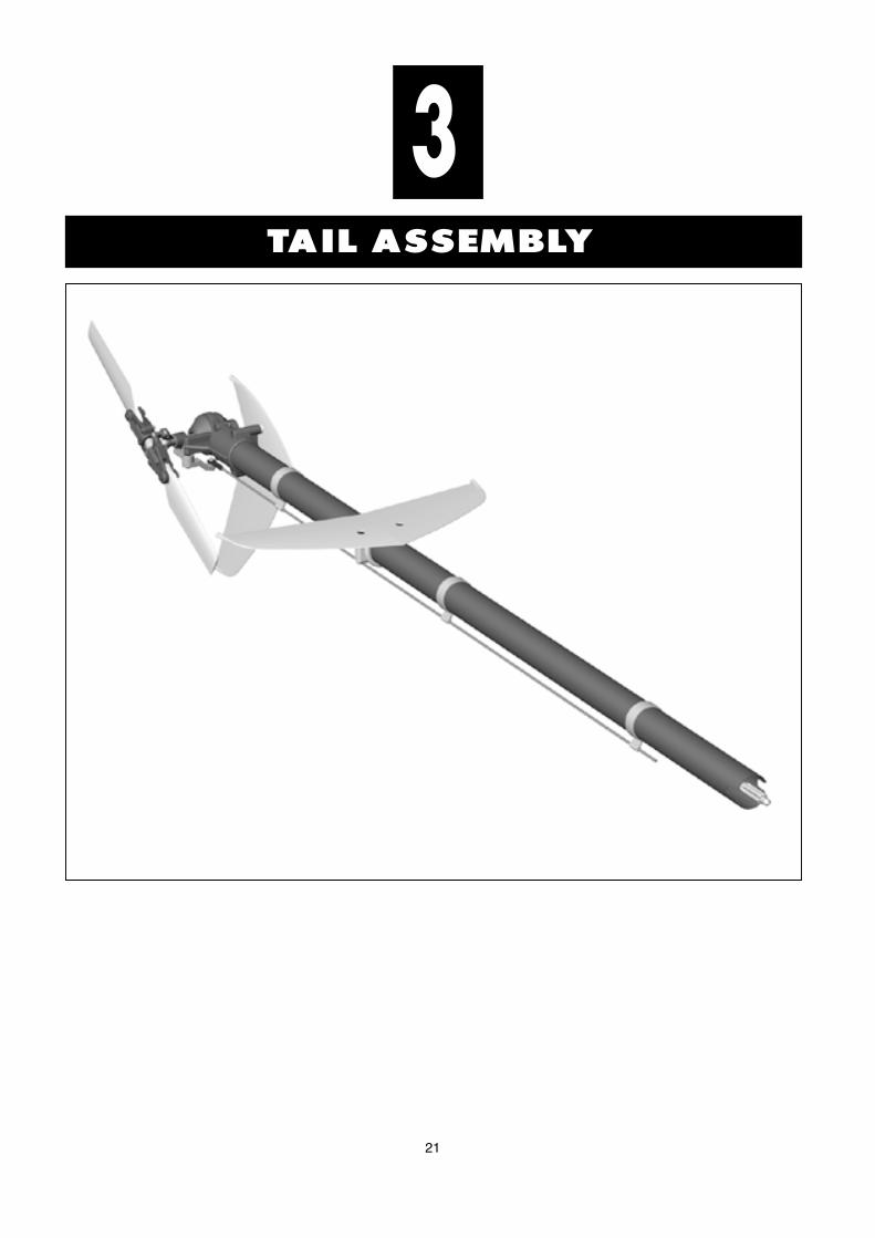
TAIL ASSEMBLY
3
22
No. Material No. Description Qty
1 HMM3B M3 Locknut 4
2 HSE3-12B M3x12 Self-Tapping Screw 2
3 HMC3-14B M3x14 Socket Screw 2
4 HMC3-30B M3x30 Socket Screw 2
5 BK0348 Tail Control Rod B (In BAG O) 1
6 BK0430 Tail Boom (In BAG O) 1
7 BK0403 Rod Guide 3
8 BK0399 Vertical Fin 1
9 BK0400 Stabilizer Fin 1
No. Material No. Description Qty
10 BK0401 Stabilizer Fin Bracket 1
11 BK0404 Tail Rotor Blade 2
12 BV0423 Tail Drive Shaft BRG (In BAG O) 1
13 BV0367 Tail Drive Shaft (In BAG O) 1
14 3-1-1 Tail Transmission Subassembly 1
15 BK0086 Ball Link 4.8x20 1
16 HMC2612B M2.6x12 Socket Screw 2
17 HMM26B M2.6 Locknut 2
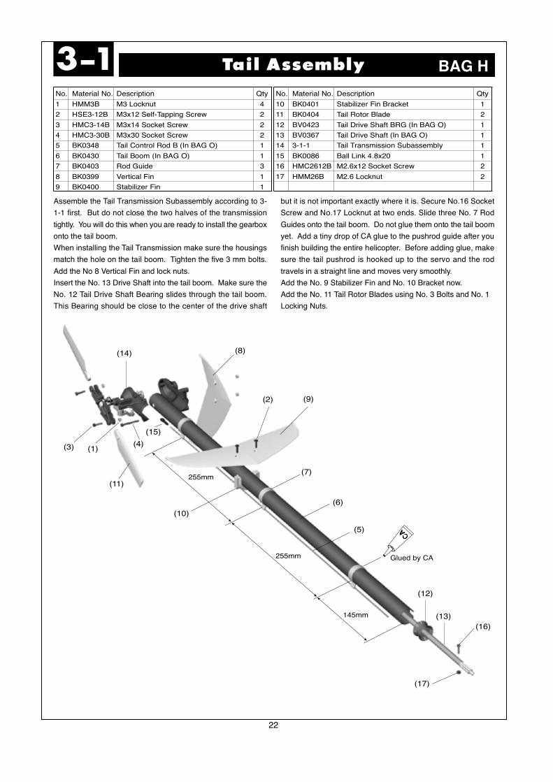
Tail Assembly3-1 BAG H
Assemble the Tail Transmission Subassembly according to 3-
1-1 first. But do not close the two halves of the transmission
tightly. You will do this when you are ready to install the gearbox
onto the tail boom.
When installing the Tail Transmission make sure the housings
match the hole on the tail boom. Tighten the five 3 mm bolts.
Add the No 8 Vertical Fin and lock nuts.
Insert the No. 13 Drive Shaft into the tail boom. Make sure the
No. 12 Tail Drive Shaft Bearing slides through the tail boom.
This Bearing should be close to the center of the drive shaft
but it is not important exactly where it is. Secure No.16 Socket
Screw and No.17 Locknut at two ends. Slide three No. 7 Rod
Guides onto the tail boom. Do not glue them onto the tail boom
yet. Add a tiny drop of CA glue to the pushrod guide after you
finish building the entire helicopter. Before adding glue, make
sure the tail pushrod is hooked up to the servo and the rod
travels in a straight line and moves very smoothly.
Add the No. 9 Stabilizer Fin and No. 10 Bracket now.
Add the No. 11 Tail Rotor Blades using No. 3 Bolts and No. 1
Locking Nuts.
(16)
(17)
(9)(2)
(8)(14)
(4)
(15)
(11)
(1)(3)
(10)
(7)
(6)
(5)
(12)
(13)145mm
255mm
255mm
Glued by CA
23
3-1-1 Tail Transmission Subassembly
No. Material No. Description Qty.
1 HMV6701Z d12xD18xBRG 2
2 HMJ2-8N M2x8 Self-Tapping Screw 1
3 HMM3B M3 Locknut 3
4 HME3-4B M3x4 Set Screw 1
5 HMC3-10B M3x10 Socket Screw 3
6 HMY2-12 Pin 2x12 1
7 HMJ3-20N M3x20 Self-Tapping Screw 1
8 BK0088 d3xD5x0.5 Washer 1
9 HMV740ZZ d4xD7x2.5 BRG 2
(16)
(5)
(18)
(8)
(17)
(11)
(7)
(2)
(15)
(6)(4)
(3)
(1)
(14)
(13)
(12)
(10)
(9)
No. Material No. Description Qty.
10 HMV1350 d5xD13x4 BRG 2
11 BK0346 Tail Pitch Control Lever 1
12 BK0370 Tail Case L 1
13 BK0371 Tail Case R 1
14 BK0372 Tail Input Bevel Gear 1
15 BK0373 Tail Output Bevel Gear 1
16 BK0075 Link Ball 4.8 1
17 BK0076 Collar d3xD4x10 1
18 3-1-2 Tail Rotor Subassembly 1
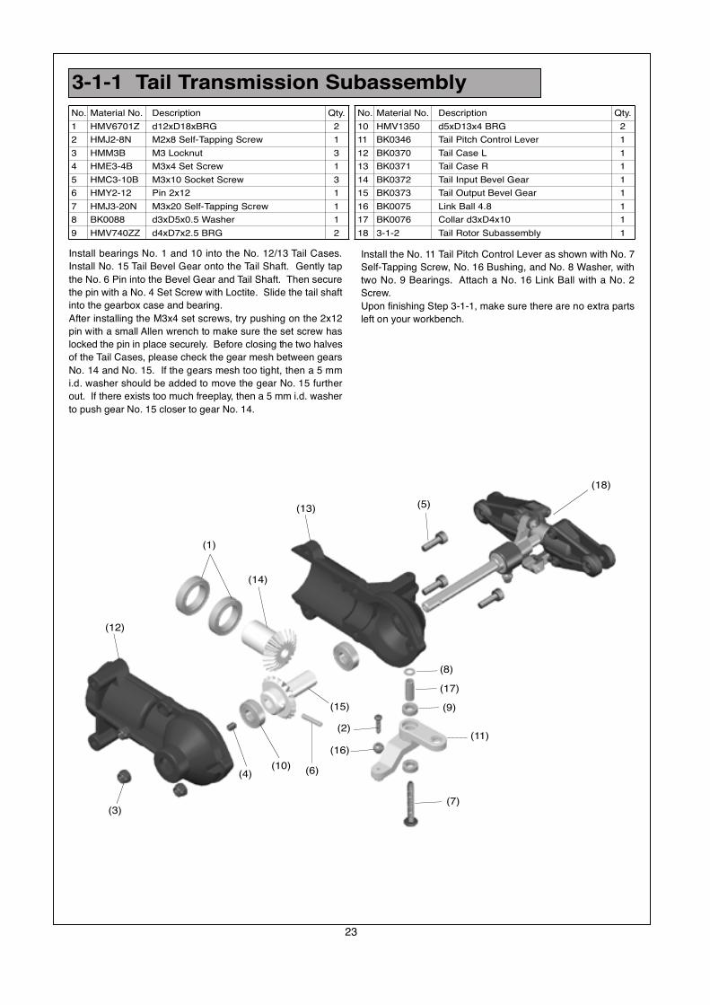
Install bearings No. 1 and 10 into the No. 12/13 Tail Cases.
Install No. 15 Tail Bevel Gear onto the Tail Shaft. Gently tap
the No. 6 Pin into the Bevel Gear and Tail Shaft. Then secure
the pin with a No. 4 Set Screw with Loctite. Slide the tail shaft
into the gearbox case and bearing.
After installing the M3x4 set screws, try pushing on the 2x12
pin with a small Allen wrench to make sure the set screw has
locked the pin in place securely. Before closing the two halves
of the Tail Cases, please check the gear mesh between gears
No. 14 and No. 15. If the gears mesh too tight, then a 5 mm
i.d. washer should be added to move the gear No. 15 further
out. If there exists too much freeplay, then a 5 mm i.d. washer
to push gear No. 15 closer to gear No. 14.
Install the No. 11 Tail Pitch Control Lever as shown with No. 7
Self-Tapping Screw, No. 16 Bushing, and No. 8 Washer, with
two No. 9 Bearings. Attach a No. 16 Link Ball with a No. 2
Screw.
Upon finishing Step 3-1-1, make sure there are no extra parts
left on your workbench.

No. Material No. Description Qty.
1 HMJ2-8N M2x8 Self-Tapping Screw 1
2 HSE2-10B M2x10 Self-Tapping Screw 2
3 HMC2510B M2.5x10 Socket Screw 4
4 HMM25 M2.5 Locknut 4
5 HMM3B M3 Locknut 2
6 HME3-18.5B M3x18.5 Set Screw 2
7 HMV1050ZZO d5xD10x4 Angular BRG 4
8 HMV1060 d6xD10X3 BRG 2
9 BK0302-1 Tail Pitch Housing A 2
10 BK0303-1 Tail Pitch Housing B 2
3-1-2 Tail Rotor Subassembly
24
No. Material No. Description Qty.
11 BK0307 Tail Rotor Hub 1
12 BK0025 Tail Pitch Control Fork 1
13 BK0026 Tail Pitch Control Link 2
14 BK0027 Tail Pitch Control Slider 1
15 BK0345 Tail Pitch Control Slide Bushing 1
16 BK0374 Tail Shaft 1
17 BK0075 Link Ball 4.8 1
18 BK0082 Collar d2xD3x4 2
19 BK0083 Pin 2x9 2
Assemble the Tail Pitch Control Slider and Pitch Control Fork
according to the drawing as follows. Insert bearings No. 8
Bearings into No. 14 Tail Pitch Control Slider. Add a tiny dropof Loctite on the "outside" surface of No. 15 Tail Pitch Control
Bushing, then slide it into the two bearings in the No. 14 Tail
Pitch Control Slider. Thread the No. 12 Pitch Control Fork onto
the brass bushing until the bushing does not have any in and
out play, but the pitch fork should still be able to spin freely in
the bearings. Add a No. 17 Link Ball with a No. 1 Screw. Thenslide the finished pitch slider onto the tail shaft.
Now assemble the Tail Blade Grip System. First install the No.
11 Tail Rotor Hub onto the No. 16 Tail Rotor Shaft. The hub
will be almost flush with the end of the tail rotor shaft. Secure
the hub to the shaft by using two No. 6 M3x18.5 set screws.
Add a tiny drop of Loctite on the set screw before threadingthem into the hub. If too much Loctite is used then it will be
impossible to remove the set screws for service in the future.
A tiny drop of Loctite is sufficient to prevent them from vibrating
out. Put a tiny drop of Loctite on the inside surface of No. 7
Bearings. Then slide two No. 7 bearings onto each end of thetail rotor hub. Add the No. 6 3mm locknut. Do not over tighten
the two locknuts because that may break the No. 6 set screw.
Now add the two piece plastic No. 9/10 Tail Pitch Housings.
Install No. 13 Tail Pitch Control Links, No. 18 Collars, and No.
2 Screws according to the drawing.Attach the Tail Pitch Control Links No. 13 to the Pitch Fork using
the small pins, No. 19.
(6)(3)
(19)
(2)
(16)
(12)
(1)
(14)
(17)
(15)
(7)
(5)
(4)
(11)
(10)
(18)
(13)(9)
(8)
Warning:Please note the assembling direction of the
angular bearing. If they are not assembled
properly as illustrated, they will easily fail
and result in unexpected danger.
Red Side In
Black Side Out
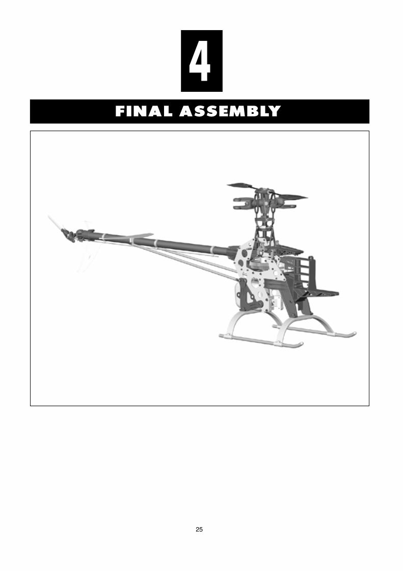
25
FINAL ASSEMBLY
4

26
No. Material No. Description Qty
1 BK0318 2.3x95 Link Rod 2
2 HMM4B M4 Locknut 1
3 BK0617 M4 Bolt 1
4 2-1 Rotor Head Assembly 1
5 BK0086 Ball Link 4.8x20 4
Installation of Rotor Head4-1
(4)
(2)
(1)
(5)
(3)
BAG I
113.5mm
(5)
(1)
Congratulation, we are almost done. Install the finished main
rotor head onto the 12 mm rotor main shaft. Secure it with a
No. 3 M4x25 socket bolt and No. 2 4 mm locknut. Make up two
113.5 mm long pushrods and attach them to the Bell-Hiller
mixing arm.
27
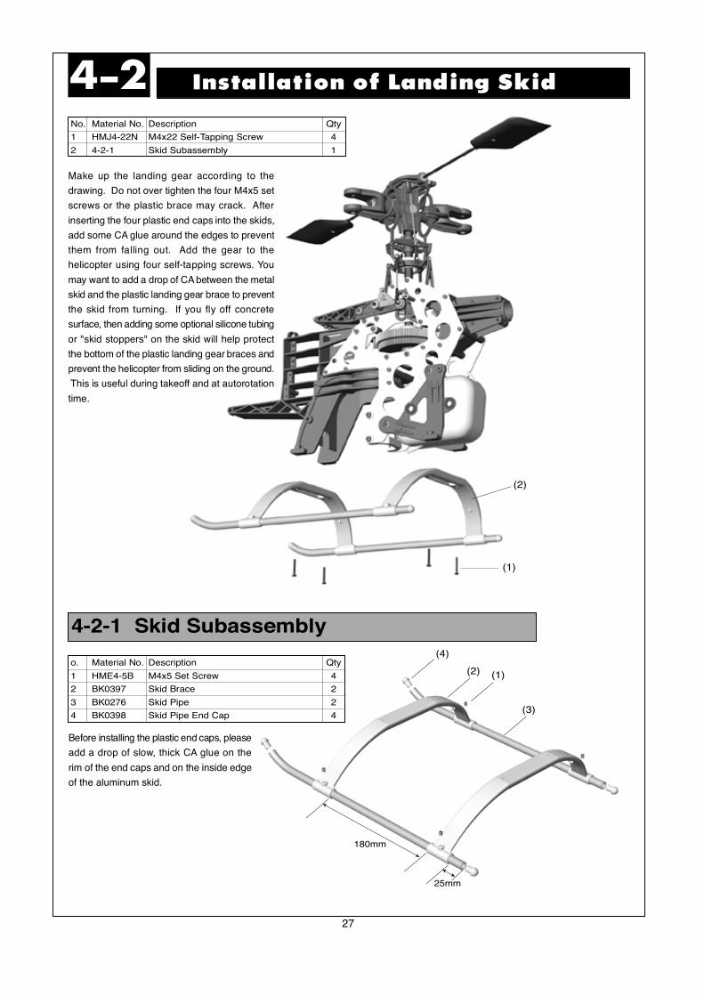
4-2-1 Skid Subassembly
No. Material No. Description Qty
1 HMJ4-22N M4x22 Self-Tapping Screw 4
2 4-2-1 Skid Subassembly 1
o. Material No. Description Qty
1 HME4-5B M4x5 Set Screw 4
2 BK0397 Skid Brace 2
3 BK0276 Skid Pipe 2
4 BK0398 Skid Pipe End Cap 4
Installation of Landing Skid4-2
(2)
(1)
(4)
(2) (1)
(3)
180mm
25mm
Before installing the plastic end caps, please
add a drop of slow, thick CA glue on the
rim of the end caps and on the inside edge
of the aluminum skid.
Make up the landing gear according to the
drawing. Do not over tighten the four M4x5 set
screws or the plastic brace may crack. After
inserting the four plastic end caps into the skids,
add some CA glue around the edges to prevent
them from falling out. Add the gear to the
helicopter using four self-tapping screws. You
may want to add a drop of CA between the metal
skid and the plastic landing gear brace to prevent
the skid from turning. If you fly off concrete
surface, then adding some optional silicone tubing
or "skid stoppers" on the skid will help protect
the bottom of the plastic landing gear braces and
prevent the helicopter from sliding on the ground.
This is useful during takeoff and at autorotation
time.
28
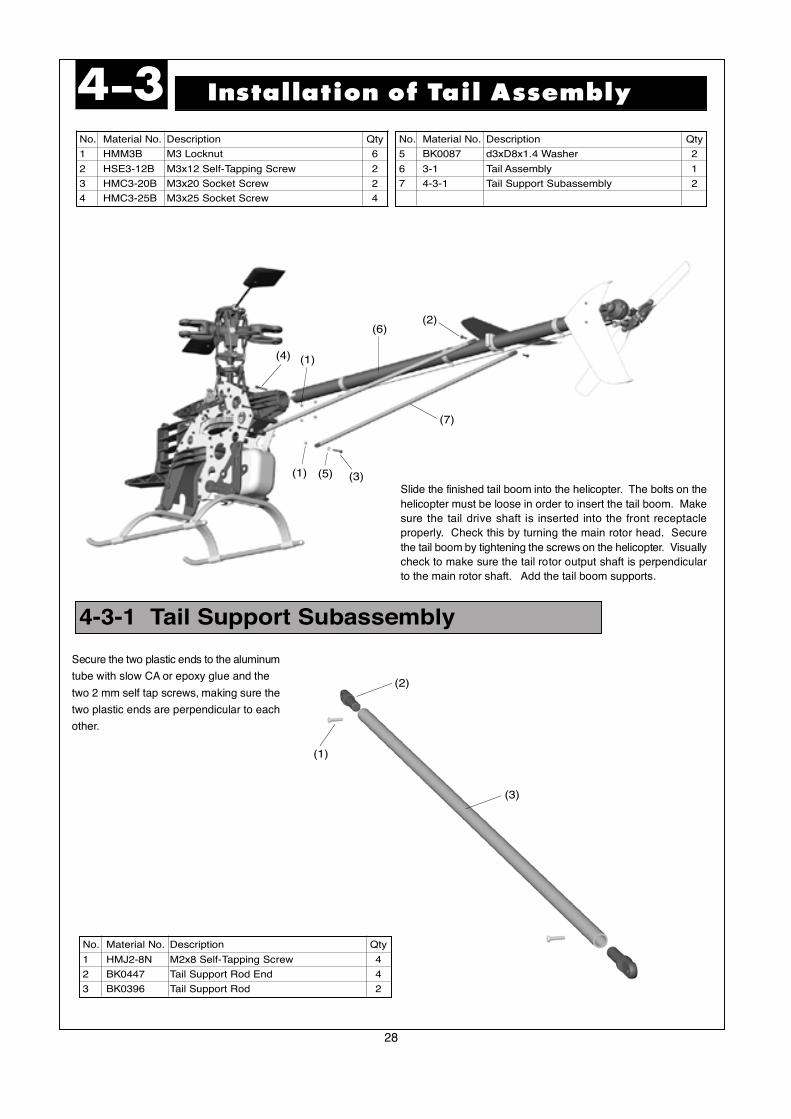
4-3-1 Tail Support Subassembly
No. Material No. Description Qty
5 BK0087 d3xD8x1.4 Washer 2
6 3-1 Tail Assembly 1
7 4-3-1 Tail Support Subassembly 2
Installation of Tail Assembly4-3
(2)(6)
(1)(4)
(1) (5) (3)
(7)
(1)
(2)
(3)
No. Material No. Description Qty
1 HMM3B M3 Locknut 6
2 HSE3-12B M3x12 Self-Tapping Screw 2
3 HMC3-20B M3x20 Socket Screw 2
4 HMC3-25B M3x25 Socket Screw 4
No. Material No. Description Qty
1 HMJ2-8N M2x8 Self-Tapping Screw 4
2 BK0447 Tail Support Rod End 4
3 BK0396 Tail Support Rod 2
Slide the finished tail boom into the helicopter. The bolts on the
helicopter must be loose in order to insert the tail boom. Make
sure the tail drive shaft is inserted into the front receptacle
properly. Check this by turning the main rotor head. Secure
the tail boom by tightening the screws on the helicopter. Visually
check to make sure the tail rotor output shaft is perpendicular
to the main rotor shaft. Add the tail boom supports.
Secure the two plastic ends to the aluminum
tube with slow CA or epoxy glue and the
two 2 mm self tap screws, making sure the
two plastic ends are perpendicular to each
other.
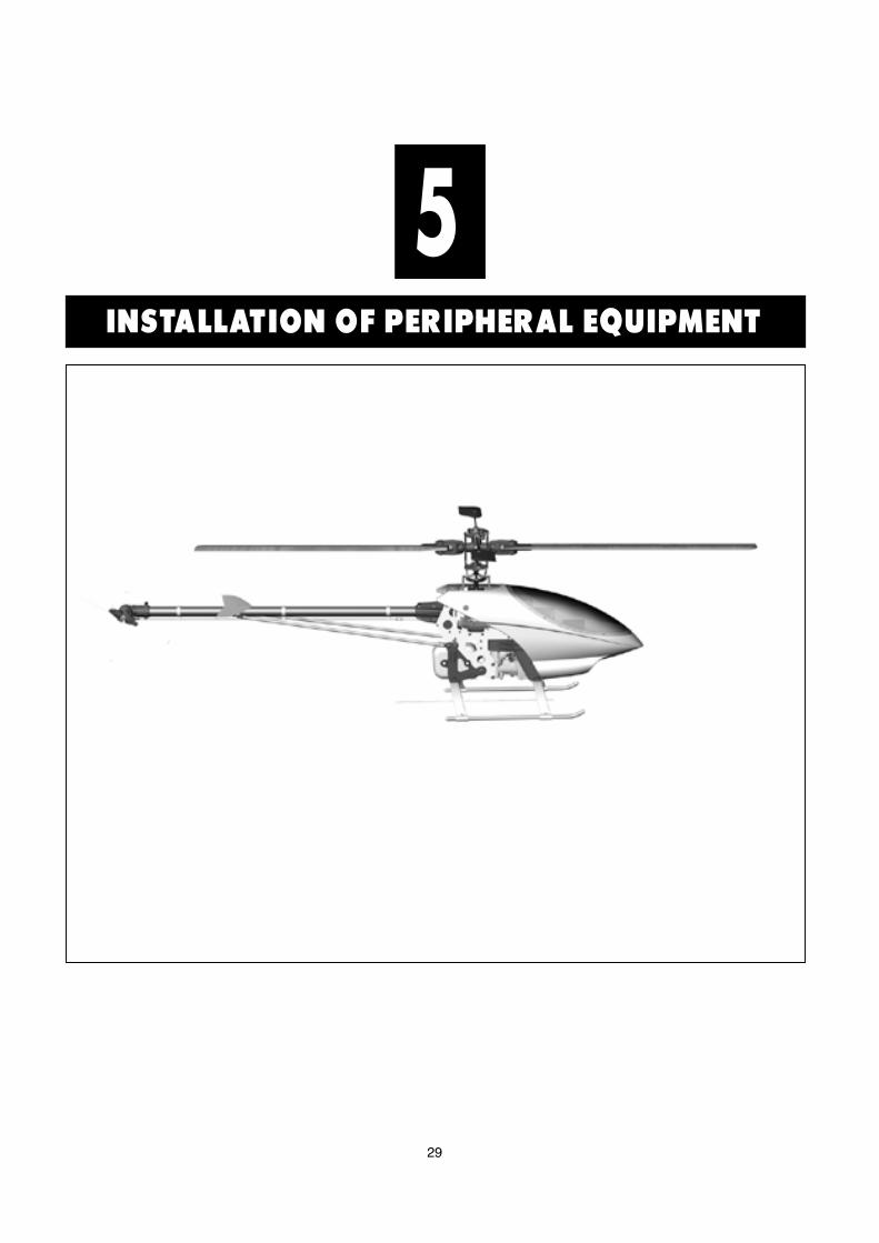
29
INSTALLATION OF PERIPHERAL EQUIPMENT
5
30
(2)
(6)
(3)
(5)
(4)
(1)
Installation of Engine5-1
(3)
(1)(2)(4)
No. Material No. Description Qty
1 5-1-1 Engine Subassembly 1
2 HMC4-18B M4x18 Socket Screw 4
3 BN1639 Muffler 1
No. Material No. Description Qty
1 ***** Heli Engine .60~.70 1
2 HMC4-8B M4x8 Socket Screw 2
3 ***** Nut ( Comes with Heli Engine) 1
4 HMO10 d9.5xD16x1 Washer 1
5 BV0380 Cooling Fan 1
6 BV0381 Clutch 1
BAG J
No. Material No. Description Qty
4 HMC4-42B M4x42 Muffler Bolt 2
5 HMT4B SPRING WASHER 2
(5)
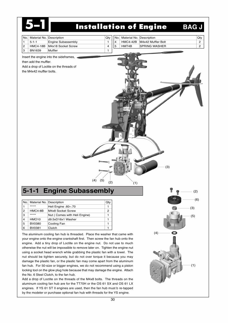
Insert the engine into the sideframes,
then add the muffler.
Add a drop of Loctite on the threads of
the M4x42 muffler bolts.
The aluminum cooling fan hub is threaded. Place the washer that came with
your engine onto the engine crankshaft first. Then screw the fan hub onto the
engine. Add a tiny drop of Loctite on the engine nut. Do not use to much
otherwise the nut will be impossible to remove later on. Tighten the engine nut
using a socket head wrench while grabbing the plastic fan with a towel. The
nut should be tighten securely, but do not over torque it because you may
damage the plastic fan, or the plastic fan may come apart from the aluminum
fan hub. For 50-size or bigger engines, we do not recommend using a piston
locking tool on the glow plug hole because that may damage the engine. Attach
the No. 6 Steel Clutch, to the fan hub.
Add a drop of Loctite on the threads of the M4x8 bolts. The threads on the
aluminum cooling fan hub are for the TT70H or the OS 61 SX and OS 61 LX
engines. If YS 61 ST II engines are used, then the fan hub must b re-tapped
by the modeler or purchase optional fan hub with threads for the YS engine.
5-1-1 Engine Subassembly
31
No. Material No. Description Qty
1 HML2 M2 Nut 4
2 HMF2-8N M2x8 Philip Machine Screw 4
3 BK0436 2.3x55 Link Rod 2
4 BK0438 2.3x88 Link Rod 1
5 HSE2614N 2.6x14 Self Tapping Screw 12
6 HME4-5B M4x5 Set Screw 2
Installation of Servo-Part 15-2
(6)
(8)
(9)
(3)
(11)
(1) (2) (10)
(5)
(12)
(7)
No. Material No. Description Qty
7 ***** Servo 5
8 BK0105 Rod Joint 1
9 BK0347 Tail Control Rod A (In BAG O) 1
10 BK0075 Link Ball 4.8 4
11 BK0086 Ball Link 4.8x20 7
12 BK0104 Servo Mounting Plate 6
BAG J
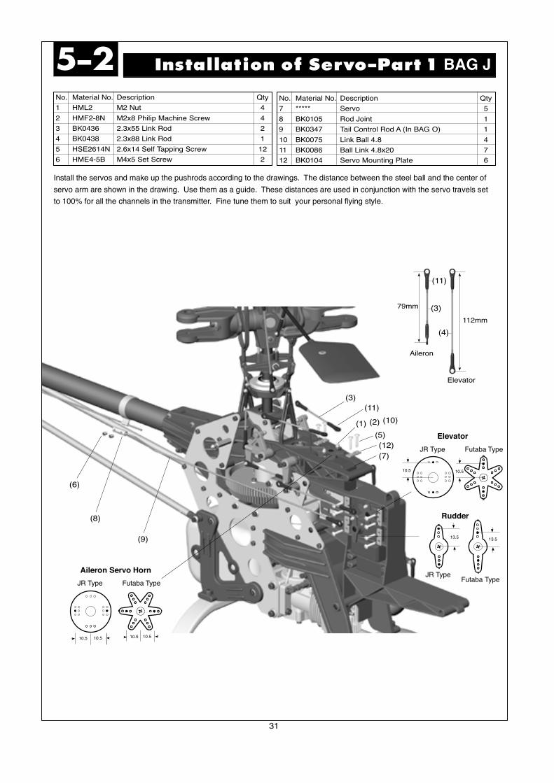
112mm
79mm
(11)
(3)
(4)
Elevator
Aileron
10.5 10.5 10.5 10.5
Aileron Servo Horn
JR Type Futaba Type
10.5
Elevator
JR Type Futaba Type
10.5
JR TypeFutaba Type
Rudder
13.5 13.5
Install the servos and make up the pushrods according to the drawings. The distance between the steel ball and the center of
servo arm are shown in the drawing. Use them as a guide. These distances are used in conjunction with the servo travels set
to 100% for all the channels in the transmitter. Fine tune them to suit your personal flying style.
32
No. Material No. Description Qty
1 HML2 M2 Nut 3
2 HMF2-8N M2x8 Philip Machine Screw 3
3 BK0436 2.3x55 Link Rod 1
4 BK0095 2.3x76 Link Rod 1
5 HSE2614N 2.6x14 Self-Tapping Screw 8
Installation of Servo-Part 25-3
(3)(1)
(2)
(9)
(5)
(8)(4)
(7)
No. Material No. Description Qty
6 ***** Servo 2
7 BK0075 Link Ball 4.8 3
8 BK0086 Ball Link 4.8x20 4
9 BK0104 Servo Mounting Plate 4
(6)
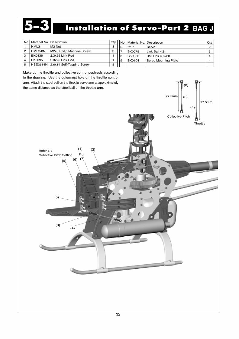
Refer 6-3
Collective Pitch Setting
97.5mm
77.5mm
(4)
Throttle
Collective Pitch
(3)
(8)
BAG J
Make up the throttle and collective control pushrods according
to the drawing. Use the outermost hole on the throttle control
arm. Attach the steel ball on the throttle servo arm at approximately
the same distance as the steel ball on the throttle arm.
33
No. Material No. Description Qty
1 ***** Switch JR Type 1
2 ***** Swtich Plate 1
3 ***** Battery(Recommend 1200mA) 1
4 ***** Reciever 1
Installation of Receiver & Gyro5-4
(6)
(2)
(8)
(1)
(5)
(4)
(3)
(7)
No. Material No. Description Qty
5 ***** Gyro AMP 1
6 ***** Gyro 1
7 BK0106 Two Touch Tape 2
8 BE1052 Antenna Pipe 1
BAG K
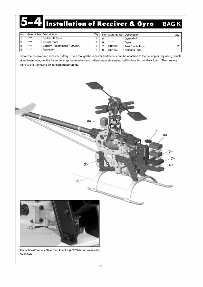
Install the receiver and receiver battery. Even though the receiver and battery can be attached to the helicopter tray using double
sided foam tape, but it is better to wrap the receiver and battery separately using half inch or 1o mm thick foam. Then secure
them to the tray using six to eight rubberbands.
The optional Remote Glow Plug Adaptor (#3803) is recommended
as shown.
34
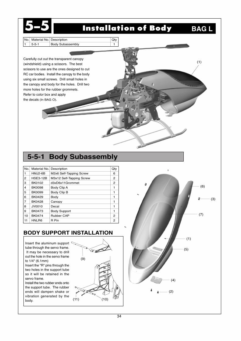
5-5-1 Body Subassembly
No. Material No. Description Qty
1 5-5-1 Body Subassembly 1
No. Material No. Description Qty
1 HMJ2-6B M2x6 Self-Tapping Screw 6
2 HSE3-12B M3x12 Self-Tapping Screw 2
3 BK0102 d3xD6x11Grommet 2
4 BK0098 Body Clip A 1
5 BK0099 Body Clip B 1
6 BK0429 Body 1
7 BK0428 Canopy 1
8 JV0010 Decal 1
9 BK0473 Body Support 1
10 BK0474 Rubber CAP 2
11 HNLR6 R Pin 2
BODY SUPPORT INSTALLATION
Insert the aluminum support
tube through the servo frame.
It may be necessary to drill
out the hole in the servo frame
to 1/4" (6.1mm)
Insert the "R" pins through the
two holes in the support tube
so it will be retained in the
servo frame.
Install the two rubber ends onto
the support tube. The rubber
ends will dampen shake or
vibration generated by the
body.
Installation of Body5-5
(1)
(6)
(3)
(7)
(5)
(1)
(4)
(2)
BAG L
Carefully cut out the transparent canopy
(windshield) using a scissors. The best
scissors to use are the ones designed to cut
RC car bodies. Install the canopy to the body
using six small screws. Drill small holes in
the canopy and body for the holes. Drill two
more holes for the rubber grommets.
Refer to color box and apply
the decals (In BAG O).
(9)
(10)(11)

35
No. Material No. Description Qty
1 BV0383 Main Rotor 2
2 BK0446 M5x35 Rotor Bolt 2
3 HMM5Z M5 Locknut 2
Since there are many after-market carbon fiber and fiberglass
blades on the market now with a 12 mm thick blade root, Thunder
Tiger has now added a complimentary Blade Grip Spacer with
each Raptor 60 Kit. This spacer is specially designed for carbon
fiber or fiberglass blades with a 12mm thick blade root. The
spacer SHOULD NOT be used on any brand or type of wood
rotor blades, including the stock Raptor 60 wood blades because
the space do not provide strength: it is just a spacer. To install
the spacer, simply bend it over and put it in place. If the blade
root is more than 12 mm, then do not use this spacer and use
the washer that comes with your blades.)
Thunder Tiger provides a good selection of high performance
680mm carbon fiber rotor blades (TTR 3836). Please check
your local dealer for more information on upgrading your rotor
blades.
See wood blade modification in page 41.
Installation of Rotor Blade5-6
(1)
(2)
(3)
BAG M
Main Rotor Grip
Raptor 60 Blade Grip Spacer for 12 mm Blade Roots
Rotor Spacer
36
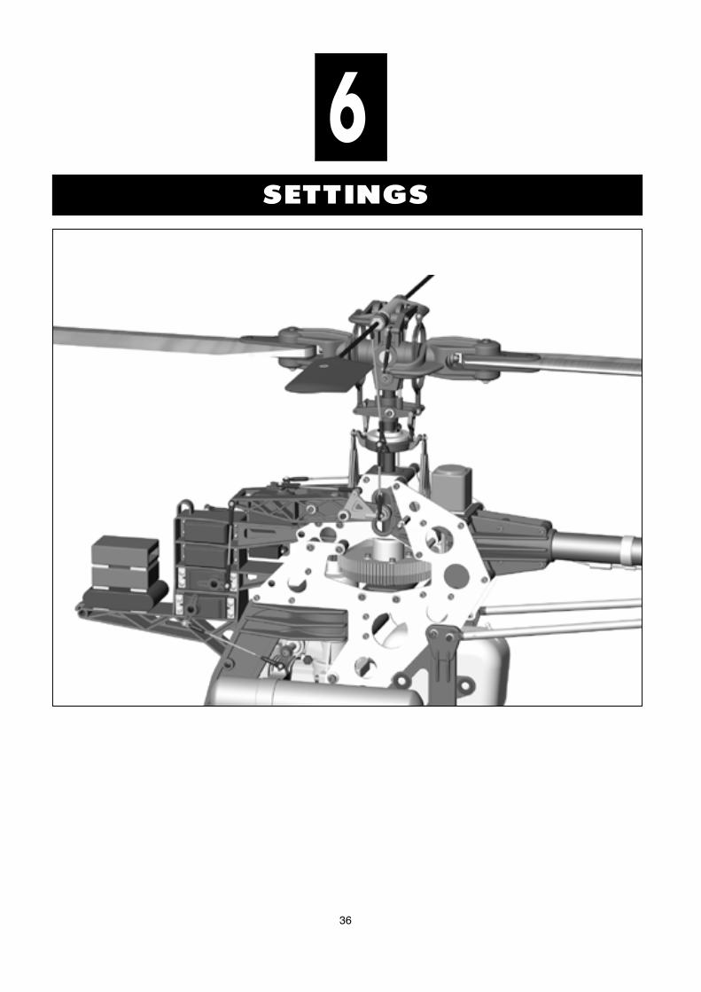
SETTINGS
6
37
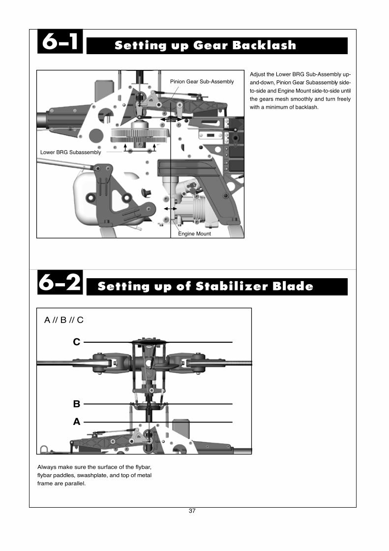
Adjust the Lower BRG Sub-Assembly up-
and-down, Pinion Gear Subassembly side-
to-side and Engine Mount side-to-side until
the gears mesh smoothly and turn freely
with a minimum of backlash.
Setting up Gear Backlash6-1
Setting up of Stabilizer Blade6-2
Engine Mount
Lower BRG Subassembly
Pinion Gear Sub-Assembly
Always make sure the surface of the flybar,
flybar paddles, swashplate, and top of metal
frame are parallel.
A
B
C
A // B // C
38
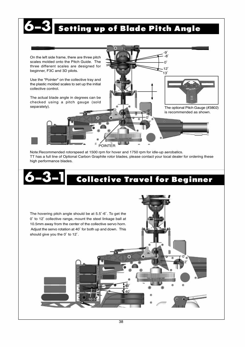
Setting up of Blade Pitch Angle6-3
Collective Travel for Beginner6-3-1
On the left side frame, there are three pitch
scales molded onto the Pitch Guide. The
three different scales are designed for
beginner, F3C and 3D pilots.
Use the "Pointer" on the collective tray and
the plastic molded scales to set up the initial
collective control.
The actual blade angle in degrees can be
checked using a pitch gauge (sold
separately).
13˚12˚
0˚
-8˚-9˚
0˚
13˚12˚
-8˚-9˚
POINTER
0˚
12˚
The hovering pitch angle should be at 5.5˚-6˚. To get the
0˚ to 12˚ collective range, mount the steel linkage ball at
10.5mm away from the center of the collective servo horn.
Adjust the servo rotation at 40˚ for both up and down. This
should give you the 0˚ to 12˚.
40˚
40˚
10.5
The optional Pitch Gauge (#3802)
is recommended as shown.
Note:Recommended rotorspeed at 1500 rpm for hover and 1750 rpm for idle-up aerobatics.
TT has a full line of Optional Carbon Graphite rotor blades, please contact your local dealer for ordering these
high performance blades.
39
Collective Travel for 3D6-3-3
Collective Travel for F3C6-3-2
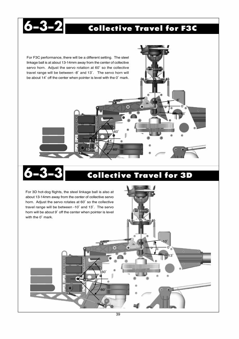
For F3C performance, there will be a different setting. The steel
linkage ball is at about 13-14mm away from the center of collective
servo horn. Adjust the servo rotation at 60˚ so the collective
travel range will be between -8˚ and 13˚. The servo horn will
be about 14˚ off the center when pointer is level with the 0˚ mark.
-8˚
0˚
13˚
For 3D hot-dog flights, the steel linkage ball is also at
about 13-14mm away from the center of collective servo
horn. Adjust the servo rotates at 60˚ so the collective
travel range will be between -10˚ and 13˚. The servo
horn will be about 9˚ off the center when pointer is level
with the 0˚ mark.
-10˚
0˚
13˚
14˚
60˚
60˚13-14
9˚
60˚
60˚

40
CONFIGURING THE RAPTOR 60 FOR 3D6-3-4
Advance 3-D SetupBeginner Setup
Use these number as a start only.Program the radio values into the transmitter. The
EXPO should be to reduce the control sensitivity
near center stick, some radio manufacturer use
negative value and some use positive value. Adjust
the pushrods to the above lengths.Then fine tune
the lengths to get the desired blade angles. Fly the
model to fine tune the value.
Pushrod length
given is from
c e n t e r t o
center of the
ball links
Extreme 3-D Setup
Beginner Setup
Besides the original settings, we have provided an additionalsetting for your reference. ( Suitable for extreme 3D flying)The only difference being the Pushrod and servo horn settingindicated with the instructions and the setting table below.
Elevator Rod Length: 66.5 69mm
Rudder Arm: 13.5 17mm
Pitch Rod Length: 77.5 73.5m
Pitch Arm: 18mm 19mm
Aileron Rod to swash: 66.5 68mm
Aileron Arm: 10.5 14mm
Swash to Hiller Assembly: 113.5 115mm
Additional Setting
43mm
113.5mm66.5mm
79mm
77.5mm
66.5mm
112mm
5˚ BEND
10.5mm
10.5mm
13.5mm
Pushrod length given
is from center to
center of the ball
links
Aileron Elevator Throttle Rudder Pitch
ATV 110% 110% 100% 120% 110%
EXPO 30% 30% 10%
Pitch Curve Low Pt. 1 Pt. 2 Pt. 3 High
Normal 15 35 60 78 95
Idle-up1 0 23 47 73 95
Idle-up2 0 23 47 73 95
Hold 10 35 60 78 100
Throttle Curve Low Pt. 1 Pt. 2 Pt. 3 High
Normal 0 25 50 75 100
Idle-up1 100 70 60 70 100
Idle-up2 100 80 70 80 100
Blade Angle Low Pt. 1 Pt. 2 Pt. 3 High
Normal -6˚ 0˚ 4~5˚ 8˚ 11.5˚
Idle-up1 -10˚ -5.5˚ 0˚ 5.5˚ 10˚
Idle-up2 -10˚ -5.5˚ 0˚ 5.5˚ 10˚
Hold -8˚ 0˚ -4˚ 8˚ 13˚
Aileron Elevator Throttle Rudder Pitch
ATV 100% 100% 100% 100% 100%
EXPO 25% 25% 30%
Pitch Curves Point 1 Point 2 Point 3 Point 4 Point 5
Normal 35 INH 50 63.5 100
Idle Up 1 0 22 40 63.5 100
Idle Up 2 7 25.5 50 63.5 100
Hold 0 25.5 50 63.5 100
Throttle Curves Point 1 Point 2 Point 3 Point 4 Point 5
Normal 35 INH 50 63.5 100
Idle Up 1 100 70 55 70 100
Idle Up 2 100 80 70 80 100
Blade Angels Point 1 Point 2 Point 3 Point 4 Point 5
Normal -3 INH 3 5.5 10
Idle Up 1 10 -5.5 0 5.5 10
Idle Up 2 -9 -5 4 5.5 10
Hold -10 -5.5 0 5.5 10
Aileron Elevator Throttle Rudder Pitch
ATV 100% 100% 100% 100% 100%
Dual Rate 70% 70% 80%Normal
Dual Rate 90% 90% 100%Idle Up 1&2
EXPO 25% 25% 30%
Radio Settings Point 1 Point 2 Point 3 Point 4 Point 5
Normal Pitch 35 INH 50 63.5 100Radio
Normal Pitch -3 INH 3 5.5 10Blade Angle
Normal Throttle 0 35 45 70 100
Aileron Elevator Throttle Rudder Pitch
ATV 90% 90% 100% 100% 100%
EXPO 30% 30% 10%
Radio Setting Low Pt. 2 Pt. 3 Pt. 4 High
Normal modeThrottle Curve
0 25 50 75 100
Normal modePitch Curve
15 35 60 80 100
Blade Angle -2˚ 3˚ 5.5˚ 9˚ 12˚

41
1. Mark around blade grips with a felt-tip marker.
2. Remove blade grips and cut covering lightly .125”
inside of mark, being careful not to cut into the blade.
3. Repeat for opposite side.
4. Trim bosses if necessary to allow tight fit to the blades.
5. Lightly sand inside of grips for better adhesion.
Apply Epoxy to blades in area shown top and bottom.
6. Attach blade grips and tighten screws.
7. Wipe off the excess Epoxy.
Idea and original art submitted by Randy Wishon,
Progressive Technologies, inc.
Dear Raptor Customers:
The stock wood blades should be operated with a main rotorspeed of no more than 1700 RPM. For 3D aerobatics
or rotor speed more than 1700RPM, it is recommended to use carbon main rotor blades. The above drawing
illustrate how to rem ove the plastic blade grips and then carefully slice away some of the covering material, and
add the "thin" type CA glue to further strengthen the wood. After installing the plastic blade grips, apply epoxy
around the seem of the plastic grip and the wood to seal it off. This adds more strength and prevent oil from seeping
through. For beginners, the best rotorspeed is around 1500 RPM. For advanced fliers, a good hovering RPM is
around 1500, and a constant 1800RPM in idle-up for 3D aerobatics.
Blade Modification
42
Always operate or fly a model helicopter in a safe manner and away from crowd, or spectators,or distractions.
Do not operate model helicopters in rainy or windy condition.
Check to make sure there is no radio interference before operating a model helicopter.
Make sure the transmitter and receiver batteries are fully charged before operation.
Make sure all controls operate properly before flight.
Model helicopter main and tail rotors operate at high rpm, therefore make sure nothing can comeinto contact with the rotors during flight.
Use only model engine fuel. Do not use gasoline, kerosene, or any other substitute.
Model engine fuel is highly flammable.
Do not let model engine fuel get in contact with eyes. Do not intake model engine fuel.
Range check the radio before flying. The servos must operate properly with the transmitterantenna collapsed and at 20 meters away.
The engine must be in the idle position before starting the engine.
Make sure the transmitter and receiver are turned on before starting the engine.
Always maintain a safe distance when operating a model helicopter.
Do not fly a model helicopter above people or cars.
Flying requires concentration. Operating a model helicopter for extended time can cause fatigue.Please rest in between flights.
Do not touch the engine or muffler immediately after the engine was run, because they will beextremely hot.
Warning (Items to watch out after flight)
Inspect the model helicopter thoroughly to make sure nothing is loosen or damaged.
Pump out the remaining fuel from the fuel tank.
Lubricate every moving part with oil to ensure a smooth operation in the future.
Warning (For Storage)
Keep the model in a cool, dry place. Avoid storage under direct sun light or near heat.
Add some engine after-run oil through the carburetor, then crank the engine by an electric starter.This help to prevent the engine bearings from rusting. After-run oils are available from hobbyshops.
Please replace any damaged parts if they are discovered during maintenance.
Attention
43
Control system check.(1) The flybar and control paddles must tilt in the proper direction and smoothly through the whole range.
(2) The rotor shaft and flybar must be straight and not damaged.
(3) The swashplate must remain clean and tilts freely.
(4) When control input are given to tilt the swashplate, make sure none of the control arms and pushrods
show any binding.
(5) The two control paddles must be leveled and parallel to each other, and point in the correct direction.
(6) Check to make sure there is no radio interfence before operating the model helicopter.
(7) Make sure the transmitter and receiver are on and all controls operate properly before flight. Range
check the radio.
(8) The engine carburetor must be in the idle position before starting the engine. Please read the engine
instruction manual on how to properly adjust the engine. Set the carburetor main needle according to
the engine instruction. Depends on the fuel and glow plug used, the carburetor idle screw may require
fine adjustment of 1/4 to 1/2 turns away from the factory setting.
(9) Fuel up the tank, move the throttle stick to idle, and connect a specially designed glow plug battery to
the glow plug.
Preflight Checklist and Starting Procedure
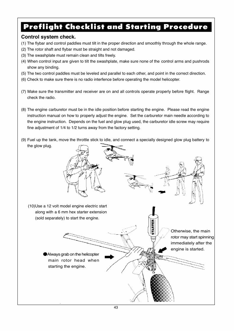
●Always grab on the helicopter
main rotor head when
starting the engine.
Otherwise, the main
rotor may start spinning
immediately after the
engine is started.
(10)Use a 12 volt model engine electric start
along with a 6 mm hex starter extension
(sold separately) to start the engine.
Flying Adjustments (1)
44
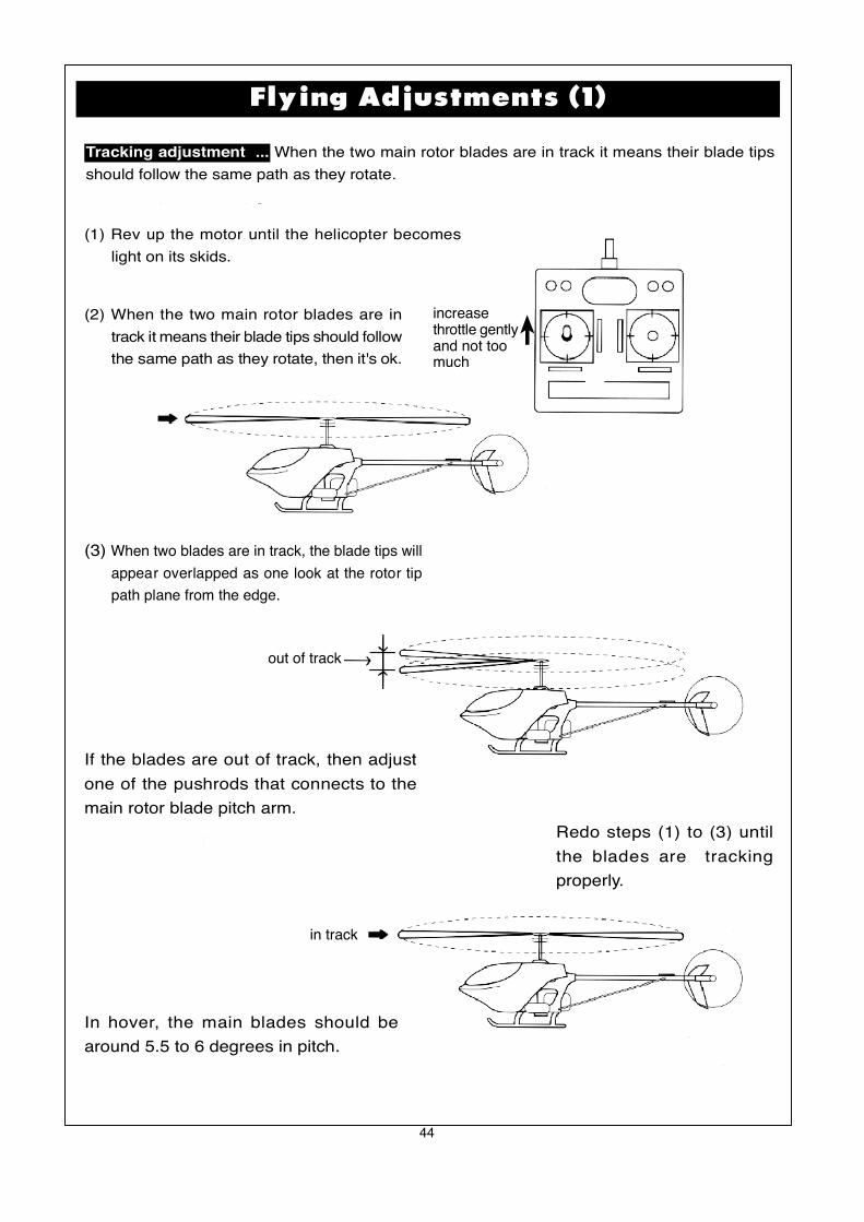
Tracking adjustment ... When the two main rotor blades are in track it means their blade tips
should follow the same path as they rotate.
(1) Rev up the motor until the helicopter becomes
light on its skids.
(2) When the two main rotor blades are in
track it means their blade tips should follow
the same path as they rotate, then it's ok.
(3) When two blades are in track, the blade tips will
appear overlapped as one look at the rotor tip
path plane from the edge.
If the blades are out of track, then adjust
one of the pushrods that connects to the
main rotor blade pitch arm.
Redo steps (1) to (3) until
the blades are tracking
properly.
In hover, the main blades should be
around 5.5 to 6 degrees in pitch.
out of track
in track
increasethrottle gentlyand not toomuch

45
Flying Adjustments (2)
Trimming: All helicopters are inherently unstable. But when a helicopter is properly trimmed, it
will not drift away or yaw by itself quickly. Use the following procedure to trim yourhelicopter.
(1) If the helicopter nose starts to yaw left or right,
then use the transmitter trim to compensate:
(3) If the helicopter noses down or up, then:
yaw right
yaw left
(A) situation: move to (b)(B) situation: move to (a)
(2) If the helicopter rolls to left or right, then:
rolls right
rolls left
(C) situation: move to (d)(d) situation: move to (c)
Noses down
Noses up
(E) situation: move to (f)(F) situation: move to (e)
46
Hover Training (1)
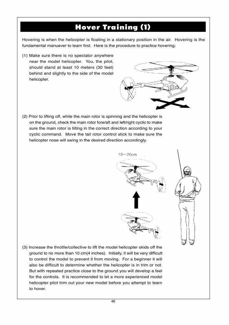
Hovering is when the helicopter is floating in a stationary position in the air. Hovering is the
fundamental manuever to learn first. Here is the procedure to practice hovering:
(1) Make sure there is no spectator anywhere
near the model helicopter. You, the pilot,
should stand at least 10 meters (30 feet)
behind and slightly to the side of the model
helicopter.
(3) Increase the throttle/collective to lift the model helicopter skids off the
ground to no more than 10 cm(4 inches). Initially, it will be very difficult
to control the model to prevent it from moving. For a beginner it will
also be difficult to determine whether the helicopter is in trim or not.
But with repeated practice close to the ground you will develop a feel
for the controls. It is recommended to let a more experienced model
helicopter pilot trim out your new model before you attempt to learn
to hover.
(2) Prior to lifting off, while the main rotor is spinning and the helicopter is
on the ground, check the main rotor fore/aft and left/right cyclic to make
sure the main rotor is tilting in the correct direction according to your
cyclic command. Move the tail rotor control stick to make sure the
helicopter nose will swing in the desired direction accordingly.
47
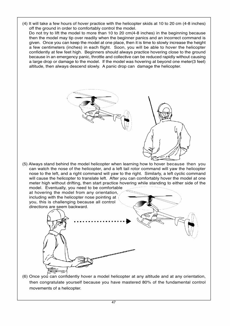
(4) It will take a few hours of hover practice with the helicopter skids at 10 to 20 cm (4-8 inches)off the ground in order to comfortably control the model.
Do not try to lift the model to more than 10 to 20 cm(4-8 inches) in the beginning becausethen the model may tip over readily when the beginner panics and an incorrect command isgiven. Once you can keep the model at one place, then it is time to slowly increase the heighta few centimeters (inches) in each flight. Soon, you will be able to hover the helicopterconfidently at few feet high. Beginners should always practice hovering close to the groundbecause in an emergency panic, throttle and collective can be reduced rapidly without causinga large drop or damage to the model. If the model was hovering at beyond one meter(3 feet)altitude, then always descend slowly. A panic drop can damage the helicopter.
(5) Always stand behind the model helicopter when learning how to hover because then youcan watch the nose of the helicopter, and a left tail rotor command will yaw the helicopternose to the left, and a right command will yaw to the right. Similarly, a left cyclic commandwill cause the helicopter to translate left. After you can comfortably hover the model at onemeter high without drifting, then start practice hovering while standing to either side of themodel. Eventually, you need to be comfortableat hovering the model from any orientation,including with the helicopter nose pointing atyou, this is challenging because all controldirections are seem backward.
(6) Once you can confidently hover a model helicopter at any altitude and at any orientation,
then congratulate yourself because you have mastered 80% of the fundamental control
movements of a helicopter.

48
Forward Flight Training
After mastering hovering flight:
(1) Start practicing moving the helicopter laterally to the left or right slowly from a 1.5 meter (60
inches) high hover. This is the beginning exercise of translational flight.
(2) After a few hours of practicing step (1) and you are comfortable with translational movement,start using some tail rotor control so the helicopter nose will point slightly to the left or right asyou fly it to the left or right. Eventually, this pattern will become a figure-eight in front of you.Please visualize these movements in your mind.
hovering at 1-1.5 meter
49
[1]The engine will not start.* The engine starting shaft will not turn:The engine may be flooded with too much fuel. Please remove the glow plug first, then turn the enginewith the electric starter until the excess fuel spits out of the glow plug hole.
* The engine turns when the electric starter is applied, but the engine will not start:(1) Is the glow plug working? Remove the glow plug and does the platinum coil glow red when a 1.5
volt battery is applied to the plug? The glow plug battery may be weak and old.(2) Is the carburetor needle properly set? Please refer to the engine instruction manual for the proper
needle setting.(3) Does the throttle control arm move properly and in the correct direction according to your transmitter
command?
* Engine will start, but quits immediately.(1) Use the transmitter to increase the throttle carburetor slightly.(2) Try a new or different type of glow plug. There are different types of glow plugs on the market for
different types of fuel and operating conditions. Seek the advice of experienced fliers and alsoexperiment with different types of glow plugs until you find the one that suits your operating conditionthe best.
*Engine runs, but the helicopter will not lift off.(1) Check the main rotor blade pitch angle, they should be set at 5.5 to 6 degrees when the transmitter
throttle/collective stick is at the center position.(2) Does the engine throttle arm move properly? The carburetor opening should be fully open when
the transmitter throttle/collective stick is moved up. The carburetor opening should be nearly closedwhen the transmitter throttle/collective stick is moved down. And the opening should be completelyclosed when the transmitter throttle/collective stick is moved down and the throttle trim is also moveddown.
(3) The carburetor needle is not set properly. Close the needle (turn it clockwise) all the way, thenopen the needle (turn it counter clockwise) 1 and 1/2 turns and try again. If the model still will notlift, then the engine maybe running too rich. The symptom is the engine exhaust has a lot of smokeand the engine coughs and wants to quit when the transmitter throttle/collective stick is moved up, then close the needle 1/8 turn at a time, until the model will lift off. Do not turn the needle too farinward, that will make the engine run too lean and over-heat and damage the engine.
[2] Helicopter problems.* The helicopter shakes.(1) Is the blade spindle bent?(2) Is the flybar bent?(3) Is the main rotor shaft bent?(4) Are the two control paddles mounted at the same distance from the rotor shaft, and the paddles
are parallel to each other, and in the proper direction?(5) Is the tail rotor shaft bent? The tail rotor blades mounted properly or damaged?(6) Are the main rotor blades damaged or mounted in the proper orientation? The blade may require
additional balancing. The blade balance can be checked by removing both blades and then useone of the 5mm blade bolt and nut to hold the two blades together like a teeter totter. Then, holdthe blade bolt with your thumb and index finger. The two blades should teeter and remain in alevel position. If not, then add some tape to the lighter blade near the blade tip until the two bladesteeter in a level position. Hobby shops also sell blade balancers that are designed solely for balancingmodel helicopter blades.
The model helicopter should be thoroughly inspected after each flying session.
(1) Check every screw and bolt to make sure none has loosened due to vibration.
(2) Check every rotating and movable part to ensure they still move smoothly and normally.
(3) Clean off the exhaust residue from the muffler, engine, and helicopter.
(4) Check all movable parts, such as gears, ball links, belt, etc. for unusual wear.
Trouble Shooting
After Flight Checklist

50
In the event the model has crashed.
Inspect the flybar, rotor shaft and the blade spindle to make sure they are not bent at all. If any item is damaged, it
must be replaced by a new part to ensure safe operation. Do not glue any broken or damaged plastic part. Do not
repair broken rotor blades. Always inspect the following items immediately:
(a). Engine starting shaft.
(b). All the gears.
(c). Main shaft, flybar and blade feathering spindle.
(d). Tail boom and supports for cracks.
(e). Drive shaft for the tail rotor.
(f). Vertical and horizontal fins.
(g). Tail rotor shaft and control system.
(h). Main and tail rotor blades.
(i). Main frame.
1 2 3 4 5 6 7 8 9 10 11 12 13 14 15 16 17 180
cm

51
PARTS LIST SECTION
α
7
52
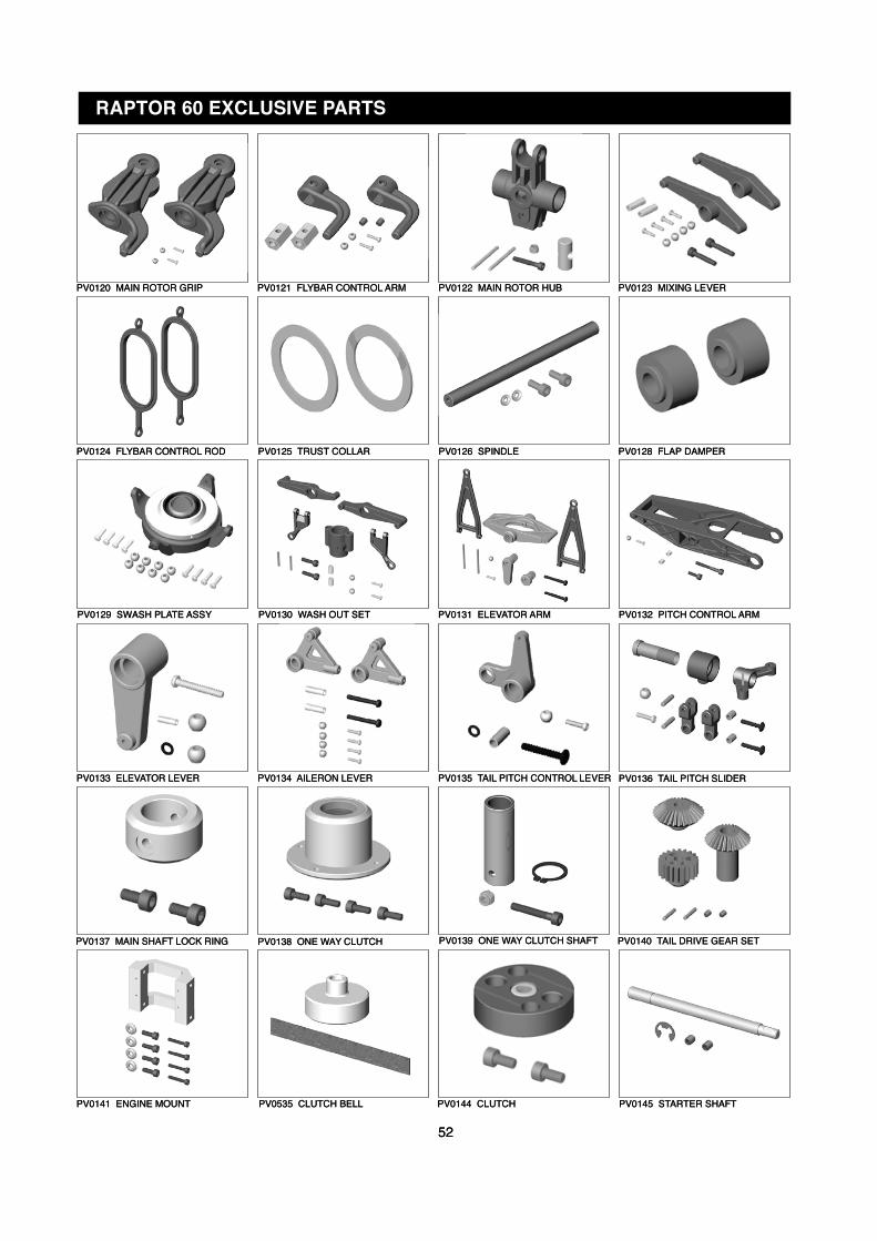
PV0141 ENGINE MOUNT PV0535 CLUTCH BELL PV0144 CLUTCH PV0145 STARTER SHAFT
PV0137 MAIN SHAFT LOCK RING PV0138 ONE WAY CLUTCH PV0139 ONE WAY CLUTCH SHAFT PV0140 TAIL DRIVE GEAR SET
PV0120 MAIN ROTOR GRIP PV0121 FLYBAR CONTROL ARM PV0122 MAIN ROTOR HUB PV0123 MIXING LEVER
PV0124 FLYBAR CONTROL ROD PV0125 TRUST COLLAR PV0126 SPINDLE PV0128 FLAP DAMPER
PV0129 SWASH PLATE ASSY PV0130 WASH OUT SET PV0131 ELEVATOR ARM
PV0133 ELEVATOR LEVER
PV0132 PITCH CONTROL ARM
PV0134 AILERON LEVER PV0135 TAIL PITCH CONTROL LEVER PV0136 TAIL PITCH SLIDER
RAPTOR 60 EXCLUSIVE PARTS
52
PV0141 ENGINE MOUNT PV0535 CLUTCH BELL PV0144 CLUTCH PV0145 STARTER SHAFT
PV0137 MAIN SHAFT LOCK RING PV0138 ONE WAY CLUTCH PV0139 ONE WAY CLUTCH SHAFT PV0140 TAIL DRIVE GEAR SET
PV0120 MAIN ROTOR GRIP PV0121 FLYBAR CONTROL ARM PV0122 MAIN ROTOR HUB PV0123 MIXING LEVER
PV0124 FLYBAR CONTROL ROD PV0125 TRUST COLLAR PV0126 SPINDLE PV0128 FLAP DAMPER
PV0129 SWASH PLATE ASSY PV0130 WASH OUT SET PV0131 ELEVATOR ARM
PV0133 ELEVATOR LEVER
PV0132 PITCH CONTROL ARM
PV0134 AILERON LEVER PV0135 TAIL PITCH CONTROL LEVER PV0136 TAIL PITCH SLIDER
RAPTOR 60 EXCLUSIVE PARTS
α
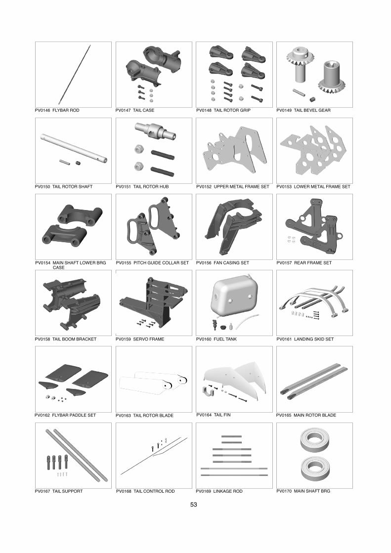
53
PV0146 FLYBAR ROD PV0147 TAIL CASE PV0148 TAIL ROTOR GRIP PV0149 TAIL BEVEL GEAR
PV0150 TAIL ROTOR SHAFT PV0151 TAIL ROTOR HUB PV0152 UPPER METAL FRAME SET PV0153 LOWER METAL FRAME SET
PV0154 MAIN SHAFT LOWER BRG CASE
PV0155 PITCH GUIDE COLLAR SET PV0156 FAN CASING SET
PV0158 TAIL BOOM BRACKET
PV0157 REAR FRAME SET
PV0159 SERVO FRAME PV0160 FUEL TANK PV0161 LANDING SKID SET
PV0162 FLYBAR PADDLE SET PV0163 TAIL ROTOR BLADE PV0164 TAIL FIN
PV0167 TAIL SUPPORT
PV0165 MAIN ROTOR BLADE
PV0168 TAIL CONTROL ROD PV0169 LINKAGE ROD PV0170 MAIN SHAFT BRG
α
54
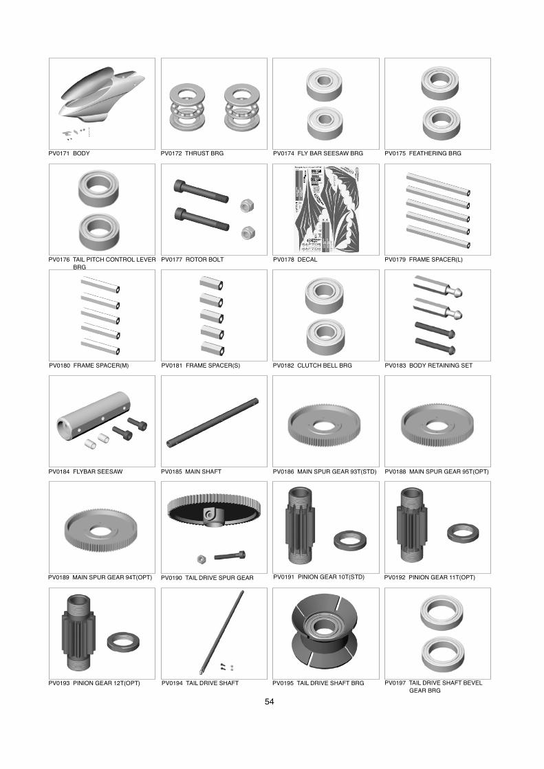
PV0171 BODY PV0172 THRUST BRG PV0174 FLY BAR SEESAW BRG PV0175 FEATHERING BRG
PV0176 TAIL PITCH CONTROL LEVER
BRG
PV0177 ROTOR BOLT PV0178 DECAL PV0179 FRAME SPACER(L)
PV0180 FRAME SPACER(M) PV0181 FRAME SPACER(S) PV0182 CLUTCH BELL BRG
PV0184 FLYBAR SEESAW
PV0183 BODY RETAINING SET
PV0185 MAIN SHAFT PV0186 MAIN SPUR GEAR 93T(STD) PV0188 MAIN SPUR GEAR 95T(OPT)
PV0189 MAIN SPUR GEAR 94T(OPT) PV0190 TAIL DRIVE SPUR GEAR PV0191 PINION GEAR 10T(STD)
PV0193 PINION GEAR 12T(OPT)
PV0192 PINION GEAR 11T(OPT)
PV0194 TAIL DRIVE SHAFT PV0195 TAIL DRIVE SHAFT BRG PV0197 TAIL DRIVE SHAFT BEVEL
GEAR BRG
α
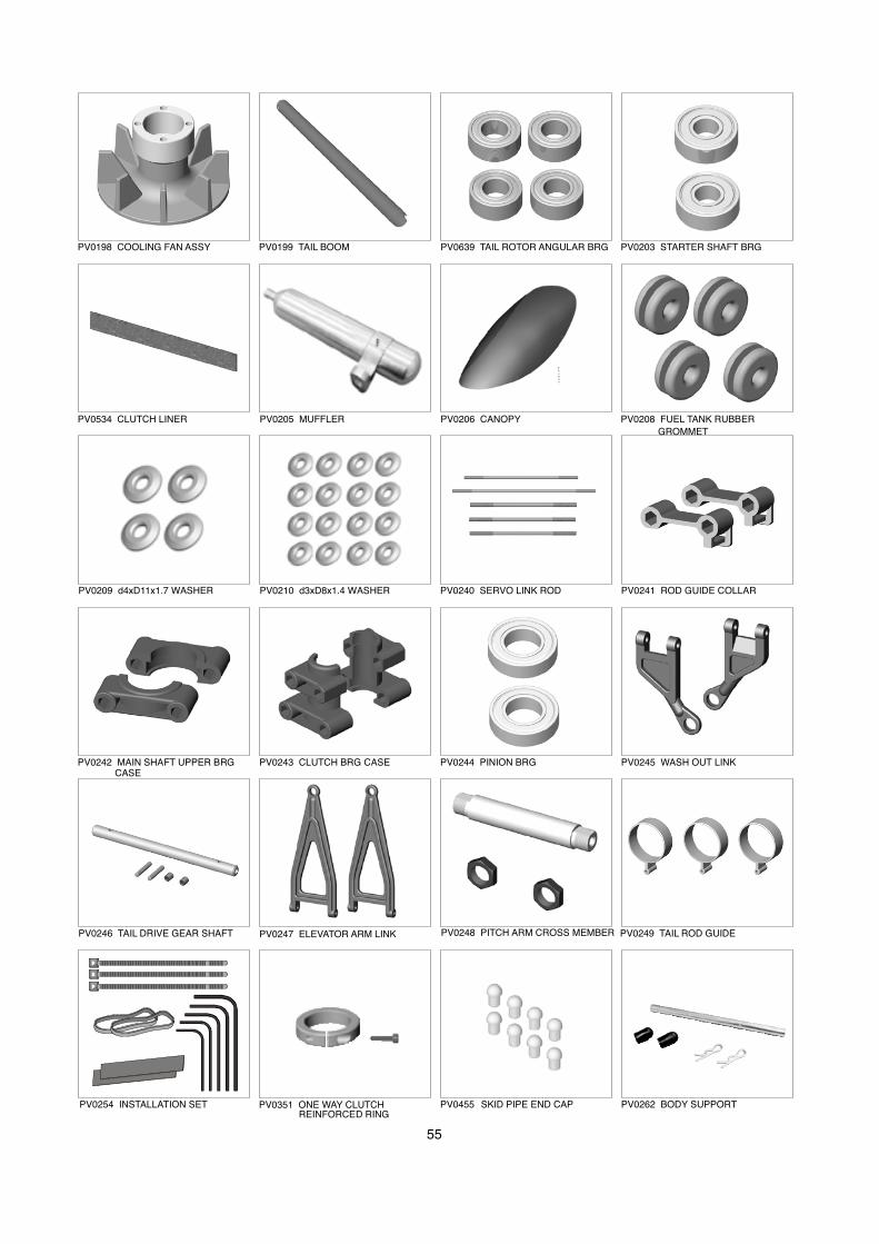
α
55
PV0198 COOLING FAN ASSY PV0199 TAIL BOOM PV0639 TAIL ROTOR ANGULAR BRG PV0203 STARTER SHAFT BRG
PV0534 CLUTCH LINER PV0205 MUFFLER PV0206 CANOPY PV0208 FUEL TANK RUBBER
GROMMET
PV0209 d4xD11x1.7 WASHER PV0210 d3xD8x1.4 WASHER PV0240 SERVO LINK ROD
PV0242 MAIN SHAFT UPPER BRG CASE
PV0241 ROD GUIDE COLLAR
PV0243 CLUTCH BRG CASE PV0244 PINION BRG PV0245 WASH OUT LINK
PV0246 TAIL DRIVE GEAR SHAFT PV0247 ELEVATOR ARM LINK PV0248 PITCH ARM CROSS MEMBER PV0249 TAIL ROD GUIDE
PV0254 INSTALLATION SET PV0262 BODY SUPPORTPV0455 SKID PIPE END CAPPV0351 ONE WAY CLUTCH REINFORCED RING
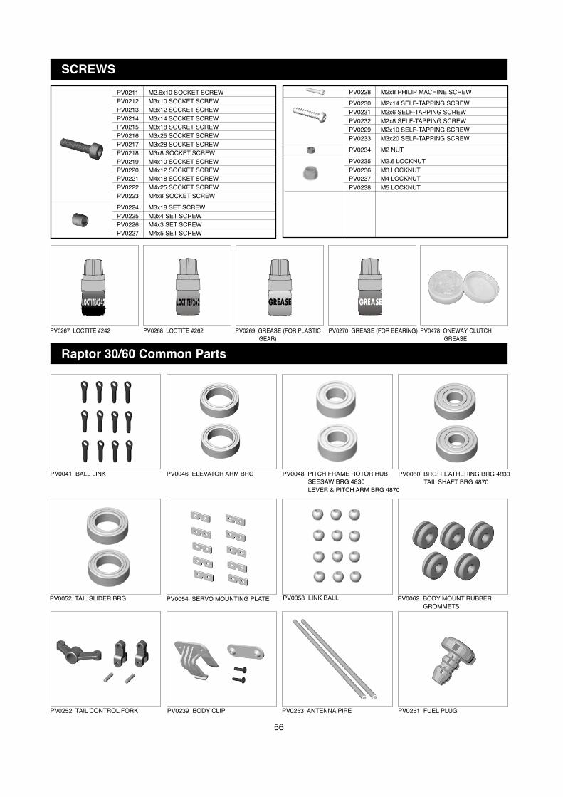
56
PV0041 BALL LINK PV0046 ELEVATOR ARM BRG PV0048 PITCH FRAME ROTOR HUB
SEESAW BRG 4830
LEVER & PITCH ARM BRG 4870
PV0050 BRG: FEATHERING BRG 4830
TAIL SHAFT BRG 4870
PV0052 TAIL SLIDER BRG PV0054 SERVO MOUNTING PLATE PV0058 LINK BALL
PV0252 TAIL CONTROL FORK
PV0062 BODY MOUNT RUBBER
GROMMETS
PV0239 BODY CLIP PV0253 ANTENNA PIPE
SCREWS
PV0211 M2.6x10 SOCKET SCREW
PV0212 M3x10 SOCKET SCREW
PV0213 M3x12 SOCKET SCREW
PV0214 M3x14 SOCKET SCREW
PV0215 M3x18 SOCKET SCREW
PV0216 M3x25 SOCKET SCREW
PV0217 M3x28 SOCKET SCREW
PV0218 M3x8 SOCKET SCREW
PV0219 M4x10 SOCKET SCREW
PV0220 M4x12 SOCKET SCREW
PV0221 M4x18 SOCKET SCREW
PV0222 M4x25 SOCKET SCREW
PV0223 M4x8 SOCKET SCREW
PV0228 M2x8 PHILIP MACHINE SCREW
PV0230 M2x14 SELF-TAPPING SCREW
PV0231 M2x6 SELF-TAPPING SCREW
PV0232 M2x8 SELF-TAPPING SCREW
PV0229 M2x10 SELF-TAPPING SCREW
PV0233 M3x20 SELF-TAPPING SCREW
PV0234 M2 NUT
PV0235 M2.6 LOCKNUT
PV0236 M3 LOCKNUT
PV0237 M4 LOCKNUT
PV0238 M5 LOCKNUT
PV0224 M3x18 SET SCREW
PV0225 M3x4 SET SCREW
PV0226 M4x3 SET SCREW
PV0227 M4x5 SET SCREW
Raptor 30/60 Common Parts
PV0251 FUEL PLUG
PV0267 LOCTITE #242 PV0268 LOCTITE #262 PV0269 GREASE (FOR PLASTIC
GEAR)
PV0270 GREASE (FOR BEARING) PV0478 ONEWAY CLUTCH
GREASE
α

α
PV0041 BALL LINK BK0086 Ball Link 4.8X20 12
PV0046 ELEVATOR ARM, BRG HMV1280 d8XD12X3.5 BRG 2 1-5-4
PV0048 BRG: PITCH FRAME & ROTOR HUB HMV840ZZ d4XD8X3 BRG 2
SEESAW 4830/ LEVER & PITCH ARM 4870
PV0050 BRG: FEATHERING 4830/TAIL SHAFT HMV1350 d5XD13X4 BRG 2 3-1-1
PV0052 TAIL SLIDER BRG HMV1060 d6XD10X3 BRG 2 3-1-1
PV0054 SERVO MOUNTING PLATE BK0104 Servo Mounting Plate 10 5-2, 5-3
PV0058 LINK BALL BK0075 Link Ball 4.8 12
PV0062 BODY MOUNT RUBBER GROMMETS BK0102 d3xD6x11 Rubber Grommet 5 5-5-1
PV0120 MAIN ROTOR GRIP BK0075 Link Ball 4.8 2 2-1
BK0319 Main Rotor Pitch Housing 2 2-1
HMJ2-10N M2X10 Self-Tapping Screw 2 2-1
PV0121 FLYBAR CONTROL ARM BK0075 Link Ball 4.8 2 2-1
BK0320 Flybar Control Arm 2 2-1
BK0323 Flybar Arm Bushing 2 2-1
HME4-5B M4X5 Set Screw 2 2-1
HMJ2-10N M2X10 Self-Tapping Screw 2 2-1
PV0122 MAIN ROTOR HUB BK0321-1 Main Rotor Hub 1 2-1
BK0329 Pin 2 2-1
BK0330 Main Rotor Hub Pin 1 2-1
HMC4-25B M4X25 Socket Screw 1 4-1
HMM4B M4 Locknut 1 4-1
PV0123 MIXING LEVER BK0324 Mixing Lever 2 2-1
BK0075 Link Ball 4.8 4 2-1
BK0410 Collar d3XD4X13 2 2-1
HMC3-18B M3X18 Socket Screw 2 2-1
BK0088 d3XD5X0.5 Washer 2 2-1
HMJ2-10N M2X10 Self-Tapping Screw 4 2-1
PV0124 FLYBAR CONTROL ROD BK0664 Flybar Control Rod 2 2-1
PV0125 TRUST COLLAR BK0325 Thrust Collar 2 2-1
PV0126 SPINDLE BK0326 Spindle 1 2-1
BK0435 Washer 2 2-1
HMC4-10B M4X10 Socket Screw 2 2-1
PV0128 FLAP DAMPER BK0328 Flap Damper 2 2-1
PV0129 SWASH PLATE ASSY BK0075 Link Ball 4.8 8 1-6-2
BV0421 Swash Plate Assy. 1 1-6-2
HMF2-8N M2X8 Philip Machine Screw 4 1-6-2
HMJ2-8N M2X8 Self-Tapping Screw 4 1-6-2
PV0130 WASH OUT SET BK0075 Link Ball 4.8 2 1-6-1
BK0341 Wash Out Base 1 1-6-1
BK0342 Flybar Control Lever 2 1-6-1
BK0343 Wash Out Link 2 1-6-1
BK0409 Collar d3XD4X7 2 1-6-1
BK0412 Pin 2X14.5 2 1-6-1
HMC3-12B M3X12 Socket Screw 2 1-6-1
HMJ2-10N M2X10 Self-Tapping Screw 2 1-6-1
PV0131 ELEVATOR ARM BK0020 Elevator Arm Shaft 1 1-5
BK0075 Link Ball 4.8 1 1-5-2
BK0335 Elevator Arm Link 2 1-5-5
BK0337 Elevator Arm Parallel Lever 1 1-5-2
BK0339 Elevator Control Arm 1 1-5-5
BK0413 Pin 2X29 2 1-5-5
HMJ2-8N M2X8 Self-Tapping Screw 1 1-5-2
HMJ3-20N M3X20 Self-Tapping Screw 2 1-5
PV0132 PITCH CONTROL ARM BK0075 Link Ball 4.8 1 1-5-4
BK0336 Pitch Frame 1 1-5-4
BK0407 Collar d3XD4X4.5 2 1-5
HMC3-10B M3X10 Socket Screw 1 1-5
HMC3-25B M3X25 Socket Screw 1 1-5
HMJ2-10N M2X10 Self-Tapping Screw 1 1-5-4
PV0133 ELEVATOR LEVER BK0075 Link Ball 4.8 2 1-5-3
BK0088 d3XD5X0.5 Washer 1 1-5
BK0410 Collar d3XD4X13 1 1-5
BK0338 Elevator Control Lever 1 1-5-3
No. NAME Parts No. Parts Name quantity ReferenceAssembly Step
57

α
HMJ2-14N M2x14 Self-Tapping Screw 1 1-5-3
PV0134 AILERON LEVER BK0075 Link Ball 4.8 4 1-5-1
BK0340 Aileron Control Arm 2 1-5-1
BK0410 Collar d3xD4x13 2 1-5
HMJ2-10N M2x10 Self-Tapping Screw 4 1-5-1
HMJ3-20N M3x20 Self-Tapping Screw 2 1-5
PV0135 TAIL PITCH CONTROL LEVER BK0075 Link Ball 4.8 1 3-1-1
BK0076 Collar d3xD4x10 1 3-1-1
BK0088 d3xD5x0.5 Washer 1 3-1-1
BK0346 Tail Pitch Control Lever 1 3-1-1
HMJ2-8N M2x8 Self-Tapping Screw 1 3-1-1
HMJ3-20N M3x20 Self-Tapping Screw 1 3-1-1
PV0136 TAIL PITCH SLIDER BK0025 Tail Pitch Control Fork 1 3-1-1
BK0026 Tail Pitch Control Link 2 3-1-1
BK0027 Tail Pitch Control Slider 1 3-1-1
BK0075 Link Ball 4.8 1 3-1-1
BK0082 Collar d2xD3x4 2 3-1-1
BK0083 Pin 2x9 2 3-1-1
BK0345 Tail Pitch Control Slide Bushing 1 3-1-1
HMJ2-8N M2x8 Self-Tapping Screw 1 3-1-1
HSE2-10B M2x10 Self-Tapping Screw 2 3-1-1
PV0137 MAIN SHAFT LOCK RING BK0234 Lock Ring 1 1-6
HMC3-6B M3x6 Socket Screw 2 1-6
PV0138 ONE WAY CLUTCH BV0368 Auto Rotation Clutch 1 1-6-3
HMC3-8B M3x8 Socket Screw 4 1-6-3
PV0139 ONE WAY CLUTCH SHAFT BK0359 One Way Clutch Shaft 1 1-6-3
HMC4-25B M4x25 Socket Screw 1 1-6
HMM4B M4 Locknut 1 1-6
HMQ16 Retaining Ring 1 1-6-3
PV0140 TAIL DRIVE GEAR SET BK0362 Tail Drive Bevel Gear A 1 1-2-2
BK0363 Tail Drive Bevel Gear B 1 1-2-2
BK0364 Tail Drive Pinion 1 1-2-2
BK0414 Pin 2x12 2 1-6-2
HME3-4B M3x4 Set Screw 2 1-6-2
PV0141 ENGINE MOUNT BK0349 Engine Mount 1 1-2
BK0435 d4xD11x1.7 Washer 4 1-2
HMC4-12B M4x12 Socket Screw 4 1-2
HMC4-18B M4x18 Socket Screw 4 5-1
PV0535 CLUTCH BELL BK0886 Clutch Liner 1 1-1-2
BV0431 Clutch Bell Set 1 1-1-2
PV0144 CLUTCH BV0381 Clutch BRG Housing 1 1-1-2
HMC4-8B M4x8 Socket Screw 2 5-1-1
PV0145 STARTER SHAFT BK0361 Starter Shaft 1 1-1-2
HME4-5B M4x5 Set Screw 2 1-1-2
HMS5 M5x8 E Ring 1 1-1-2
PV0146 FLYBAR ROD BK0434 Flybar Rod 1 2-1
PV0147 TAIL CASE BK0370 Tail Case L 1 3-1-1
BK0371 Tail Case R 1 3-1-1
HMC3-10B M3x10 Socket Screw 3 3-1-1
HMM3B M3 Locknut 3 3-1-1
PV0148 TAIL ROTOR GRIP BK0302-1 Tail Pitch Housing A 2 3-1-1
BK0303-1 Tail Pitch Housing B 2 3-1-1
HMC2610B M2.6x10 Socket Screw 4 3-1-1
HMC3-14B M3x14 Socket Screw 2 3-1
HMM26B M2.6 Locknut 4 3-1-1
HMM3B M3 Locknut 2 3-1
PV0149 TAIL BEVEL GEAR BK0372 Tail Input Bevel Gear 1 3-1-1
BK0373 Tail Output Bevel Gear 1 3-1-1
BK0414 Pin 2x12 1 3-1-1
HME3-4B M3x4 Set Screw 1 3-1-1
PV0150 TAIL ROTOR SHAFT BK0374 Tail Shaft 1 3-1-1
BK0414 Pin 2x12 1 3-1-1
HME3-4B M3x4 Set Screw 1 3-1-1
PV0151 TAIL ROTOR HUB BK0307 Tail Rotor Hub 1 3-1-1
58
No. NAME Parts No. Parts Name quantity ReferenceAssembly Step

α
HME3-18B M3x18 Set Screw 2 3-1-1
HMM3B M3 Locknut 2 3-1-1
PV0152 UPPER METAL FRAME SET BK0375 Upper Metal Frame 2 1-1
PV0153 LOWER METAL FRAME SET BK0376 Lower Metal Frame 2 1-2
PV0154 MAIN SHAFT LOWER BRG CASE BK0387 Lower BRG Case 2 1-2-1
PV0155 PITCH GUIDE COLLAR SET BK0384 Pitch Guide Collar L 1 1-1-3
BK0385 Pitch Guide Collar R 1 1-1-4
PV0156 FAN CASING SET BK0378 Fan Casing L 1 1-2-3
BK0379 Fan Casing R 1 1-2-3
PV0157 REAR FRAME SET BK0380 Rear Frame L 1 1-2
BK0381 Rear Frame R 1 1-2
BK0629 Washer 4 1-2
PV0158 TAIL BOOM BRACKET BK0382 Tail Boom Bracket L 1 1-2-2
BK0383 Tail Boom Bracket R 1 1-2-2
PV0159 SERVO FRAME BK0377 Servo Frame 1 1-4
HSE3-12B M3x12 Self-Tapping Screw 6 1-4
PV0160 FUEL TANK BK0402 Fuel Tank 1 1-2-4
BB0373 Silicone Tube 1 1-2-4
BV0355 Fuel Nipple 1 1-2-4
BK0062 Fuel Tank Stopper 1 1-2-4
BE1867 Clunk Weight 1 1-2-4
PV0161 LANDING SKID SET BK0276 Skid Pipe 2 4-2-1
BK0397 Skid Brace 2 4-2-1
BK0398 Skid Pipe End Cap 4 4-2-1
HME4-5B M4x5 Set Screw 4 4-2-1
HMJ3-20N M3x20 Self-Tapping Screw 4 4-2-1
PV0162 FLYBAR PADDLE SET BK0406 Paddle Root 2 2-1
BK0416 Paddle Stopper 2 2-1
BK0432 Flybar Paddle 2 2-1
HME4-3B M4x3 Set Screw 4 2-1
PV0163 TAIL ROTOR BLADE BK0404 Tail Rotor Blade 2 3-1
PV0164 TAIL FIN BK0399 Vertical Fin 1 3-1
BK0400 Stabilizer Fin 1 3-1
BK0401 Stabilizer Fin Bracket 1 3-1
HMC3-30B M3x30 Socket Screw 2 3-1
HMM3B M3 Locknut 2 3-1
HSE3-12B M3x12 Self-Tapping Screw 2 3-1
PV0165 MAIN ROTOR BLADE BV0383 Main Rotor 2 5-6
PV0167 TAIL SUPPORT BK0396 Tail Support Rod 2 4-3-1
BK0447 Tail Support Rod End 4 4-3-1
HMJ2-8N M2x8 Self-Tapping Screw 4 4-3-1
PV0168 TAIL CONTROL ROD BK0086 Ball Link 4.8x20 2 3-1
BK0105 Rod Joint 1 5-2
BK0347 Tail Control Rod A 1 5-2
BK0348 Tail Control Rod B 1 3-1
HME4-5B M4x5 Set Screw 2 5-2
PV0169 LINKAGE ROD BK0093 2x46 Link Rod 3 1-5
BK0292 2.3x24 Link Rod 2 2-1
BK0318 2.3x95 Link Rod 2 4-1
PV0170 MAIN SHAFT BRG HMV6901ZZ d12xD24x6 BRG 2 1-1-1
PV0171 BODY BK0098 Body Clip A 1 5-5-1
BK0099 Body Clip B 1 5-5-1
BK0102 d3xD6x11 Rubber Grommet 2 5-5-1
BK0428 Canopy 1 5-5-1
BK0429 Body 1 5-5-1
HMJ2-6B M2x6 Self-Tapping Screw 8 5-5-1
HSE3-12B M3x12 Self-Tapping Screw 2 5-5-1
PV0172 THRUST BRG HMX0816 d8xD16x5 Thrust Bearing 2 2-1
PV0174 FLY BAR SEESAW BRG HMV694ZZ d4xD11x4 BRG 2 2-1
PV0175 FEATHERING BRG HMV1680 d8xD16x5 BRG 2 2-1
PV0176 TAIL PITCH CONTROL LEVER BRG HMV740ZZ d4xD7x2.5 BRG 2 3-1-1
PV0177 ROTOR BOLT BK0446 Rotor Bolt 2 5-6
HMM5Z M5 Locknut 2 5-6
PV0178 DECAL,4870 JV0010 Decal 1 5-5-1
No. NAME Parts No. Parts Name quantity ReferenceAssembly Step
59

α
PV0179 FRAME SPACER(L) BK0390 Frame Spacer L 13 1-2-1
PV0180 FRAME SPACER(M) BK0391 Frame Spacer M 8 1-1-1
PV0181 FRAME SPACER(S) BK0392 Frame Spacer S 12 1-1-3
PV0182 CLUTCH BELL BRG HMV1360Z d6xD13x5 BRG 2 1-1-2
PV0183 BODY RETAINING SET BK0103 Body Fitting Pin 2 1-3
HSA3-22 M3x22 Button Head Socket Screw 2 1-1
PV0184 FLYBAR SEESAW BK0322 Flybar Seesaw Hub 1 2-1
BK0408 Collar d3xD4x5.5 2 2-1
HMC3-10B M3x10 Socket Screw 2 2-1
PV0185 MAIN SHAFT BK0360 Main Shaft 1 1-6
PV0186 MAIN SPUR GEAR 93T(STD) BK0420 Main Spur Gear 93T 1 1-6-3
PV0188 MAIN SPUR GEAR 95T(OPT) BK0431 Main Spur Gear 95T 1 1-6-3
PV0189 MAIN SPUR GEAR 94T(OPT) BK0421 Main Spur Gear 94T 1 1-6-3
PV0190 TAIL DRIVE SPUR GEAR BK0357 Tail Drive Spur Gear 83T 1 1-6-3
HMC4-25B M4x25 Socket Screw 1 1-6
HMM4B M4 Locknut 1 1-6
PV0191 PINION GEAR 10T(STD) BK0355 Drive Pinion 10T 1 1-1-2
BK0366 Pinion Gear Nut 1 1-1-2
PV0192 PINION GEAR 11T(OPT) BK0422 Drive Pinion 11T 1 1-1-2
BK0366 Pinion Gear Nut 1 1-1-2
PV0193 PINION GEAR 12T(OPT) BK0423 Drive Pinion 12T 1 1-1-2
BK0366 Pinion Gear Nut 1 1-1-2
PV0194 TAIL DRIVE SHAFT BV0367 Tail Drive Shaft 1 3-1
PV0195 TAIL DRIVE SHAFT BRG BV0423 Tail Drive Shaft BRG 1 3-1
PV0197 TAIL DRIVE SHAFT BEVEL GEAR BRG HMV6701Z d12xD18x4 BRG 2 3-1-1
PV0198 COOLING FAN ASSY BV0380 Cooling Fan Assy. 1 5-1-1
PV0199 TAIL BOOM BK0430 Tail Boom 1 3-1
PV0639 TAIL ROTOR ANGULAR BRG HMV1050ZZO d5xD10x4 BRG 4 3-1-1
PV0203 STARTER SHAFT BRG HMV696Z d6xD15x5 BRG 2 1-1-2
PV0534 CLUTCH LINER BK0886 Clutch Liner 1 1-1-2
PV0205 MUFFLER BN1639 Muffler 1 5-1
HMC4-42B M4x42 Muffler Bolt 2 5-1
HMT4B d4 Spring Washer 2 5-1
PV0206 CANOPY BK0428 Canopy 1 5-5-1
HMJ2-6B M2x6 Self- Tapping Screw 8 5-5-1
PV0208 FUEL TANK RUBBER GROMMET BK0274 Tank Rubber Grommet 4 1-2
PV0209 d4xD11x1.7 WASHER BK0435 d4xD11x1.7 Washer 4 1-2
PV0210 d3xD8x1.4 WASHER BK0087 d3xD8x1.4 Washer 16 1-2
PV0211 M2.6x10 SOCKET SCREW HMC2610B M2.6x10 Socket Screw 20
PV0212 M3x10 SOCKET SCREW HMC3-10B M3x10 Socket Screw 20
PV0213 M3x12 SOCKET SCREW HMC3-12B M3x12 Socket Screw 20
PV0214 M3x14 SOCKET SCREW HMC3-14B M3x14 Socket Screw 20
PV0215 M3x18 SOCKET SCREW HMC3-18B M3x18 Socket Screw 20
PV0216 M3x25 SOCKET SCREW HMC3-25B M3x25 Socket Screw 20
PV0217 M3x28 SOCKET SCREW HMC3-28B M3x28 Socket Screw 20
PV0218 M3x8 SOCKET SCREW HMC3-8B M3x8 Socket Screw 20
PV0219 M4x10 SOCKET SCREW HMC4-10B M4x10 Socket Screw 20
PV0220 M4x12 SOCKET SCREW HMC4-12B M4x12 Socket Screw 20
PV0221 M4x18 SOCKET SCREW HMC4-18B M4x18 Socket Screw 20
PV0222 M4x25 SOCKET SCREW HMC4-25B M4x25 Socket Screw 20
PV0223 M4x8 SOCKET SCREW HMC4-8B M4x8 Socket Screw 20
PV0224 M3x18 SET SCREW HME3-18B M3x18 Set Screw 20
PV0225 M3x4 SET SCREW HME3-4B M3x4 Set Screw 20
PV0226 M4x3 SET SCREW HME4-3B M4x3 Set Screw 20
PV0227 M4x5 SET SCREW HME4-5B M4x5 Set Screw 20
PV0228 M2x8 PHILIP MACHINE SCREW HMF2-8N M2x8 Philip Machine Screw 20
PV0230 M2x14 SELF-TAPPING SCREW HMJ2-14N M2x14 Self-Tapping Screw 20
PV0231 M2x6 SELF-TAPPING SCREW HMJ2-6B M2x6 Self-Tapping Screw 20
PV0232 M2x8 SELF-TAPPING SCREW HMJ2-8N M2x8 Self-Tapping Screw 20
PV0229 M2x10 SELF-TAPPING SCREW HMJ2-10N M2x10 Self-Tapping Screw 20
PV0233 M3x20 SELF-TAPPING SCREW HMJ3-20N M3x20 Self-Tapping Screw 20
PV0234 M2 NUT HML2 M2 Nut 20
PV0235 M2.6 LOCK NUT HMM26B M2.6 Locknut 20
PV0236 M3 LOCK NUT HMM3B M3 Locknut 20
60
No. NAME Parts No. Parts Name quantity ReferenceAssembly Step
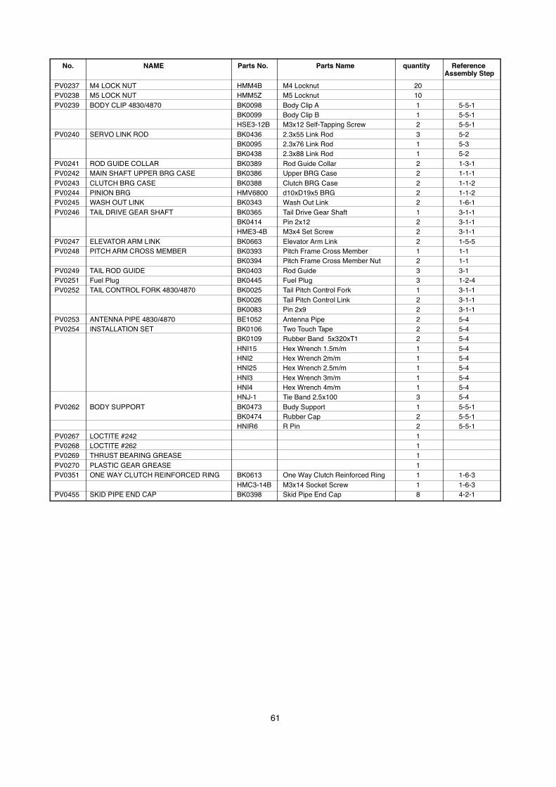
α
PV0237 M4 LOCK NUT HMM4B M4 Locknut 20
PV0238 M5 LOCK NUT HMM5Z M5 Locknut 10
PV0239 BODY CLIP 4830/4870 BK0098 Body Clip A 1 5-5-1
BK0099 Body Clip B 1 5-5-1
HSE3-12B M3x12 Self-Tapping Screw 2 5-5-1
PV0240 SERVO LINK ROD BK0436 2.3x55 Link Rod 3 5-2
BK0095 2.3x76 Link Rod 1 5-3
BK0438 2.3x88 Link Rod 1 5-2
PV0241 ROD GUIDE COLLAR BK0389 Rod Guide Collar 2 1-3-1
PV0242 MAIN SHAFT UPPER BRG CASE BK0386 Upper BRG Case 2 1-1-1
PV0243 CLUTCH BRG CASE BK0388 Clutch BRG Case 2 1-1-2
PV0244 PINION BRG HMV6800 d10xD19x5 BRG 2 1-1-2
PV0245 WASH OUT LINK BK0343 Wash Out Link 2 1-6-1
PV0246 TAIL DRIVE GEAR SHAFT BK0365 Tail Drive Gear Shaft 1 3-1-1
BK0414 Pin 2x12 2 3-1-1
HME3-4B M3x4 Set Screw 2 3-1-1
PV0247 ELEVATOR ARM LINK BK0663 Elevator Arm Link 2 1-5-5
PV0248 PITCH ARM CROSS MEMBER BK0393 Pitch Frame Cross Member 1 1-1
BK0394 Pitch Frame Cross Member Nut 2 1-1
PV0249 TAIL ROD GUIDE BK0403 Rod Guide 3 3-1
PV0251 Fuel Plug BK0445 Fuel Plug 3 1-2-4
PV0252 TAIL CONTROL FORK 4830/4870 BK0025 Tail Pitch Control Fork 1 3-1-1
BK0026 Tail Pitch Control Link 2 3-1-1
BK0083 Pin 2x9 2 3-1-1
PV0253 ANTENNA PIPE 4830/4870 BE1052 Antenna Pipe 2 5-4
PV0254 INSTALLATION SET BK0106 Two Touch Tape 2 5-4
BK0109 Rubber Band 5x320xT1 2 5-4
HNI15 Hex Wrench 1.5m/m 1 5-4
HNI2 Hex Wrench 2m/m 1 5-4
HNI25 Hex Wrench 2.5m/m 1 5-4
HNI3 Hex Wrench 3m/m 1 5-4
HNI4 Hex Wrench 4m/m 1 5-4
HNJ-1 Tie Band 2.5x100 3 5-4
PV0262 BODY SUPPORT BK0473 Budy Support 1 5-5-1
BK0474 Rubber Cap 2 5-5-1
HNIR6 R Pin 2 5-5-1
PV0267 LOCTITE #242 1
PV0268 LOCTITE #262 1
PV0269 THRUST BEARING GREASE 1
PV0270 PLASTIC GEAR GREASE 1
PV0351 ONE WAY CLUTCH REINFORCED RING BK0613 One Way Clutch Reinforced Ring 1 1-6-3
HMC3-14B M3x14 Socket Screw 1 1-6-3
PV0455 SKID PIPE END CAP BK0398 Skid Pipe End Cap 8 4-2-1
61
No. NAME Parts No. Parts Name quantity ReferenceAssembly Step
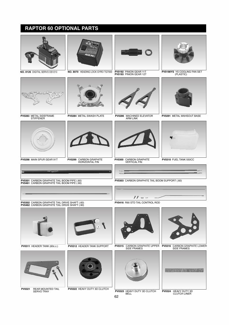
62
RAPTOR 60 OPTIONAL PARTS
PV0283 METAL SIDEFRAME STIFFENER
PV0286 MACHINED ELEVATORARM LINK
PV0298 MAIN SPUR GEAR 91T PV0299 CARBON GRAPHITEHORIZONTAL FIN
PV0300 CARBON GRAPHITEVERTICAL FIN
PV0315 CARBON GRAPHITE UPPERSIDE FRAMES
PV0198YS YS COOLING FAN SET (PLASTIC)
PV0192 PINION GEAR 11TPV0193 PINION GEAR 12T
PV0284 METAL SWASH PLATE PV0291 METAL WAHSOUT BASE
PV0301 CARBON GRAPHITE TAIL BOOM PIPE (.60)PV0461 CARBON GRAPHITE TAIL BOOM PIPE (.90)
PV0302 CARBON GRAPHITE TAIL DRIVE SHAFT (.60)PV0462 CARBON GRAPHITE TAIL DRIVE SHAFT (.90)
PV0303 CARBON GRAPHITE TAIL BOOM SUPPORT (.60)
PV0416 R90 STD TAIL CONTROL ROD
PV0310 FUEL TANK 550CC
PV0311 HEADER TANK (60c.c.) PV0312 HEADER TANK SUPPORT
PV0322 HEAVY DUTY 3D CLUTCHPV0324 HEAVY DUTY 3D
CLUTCH LINERPV0323 HEAVY DUTY 3D CLUTCH
BELL
PV0316 CARBON GRAPHITE LOWERSIDE FRAMES
NO. 8126 DIGITAL SERVO DS1213 NO. 8070 HEADING LOCK GYRO TG7000
α
PV0321 REAR MOUNTED TAILSERVO TRAY
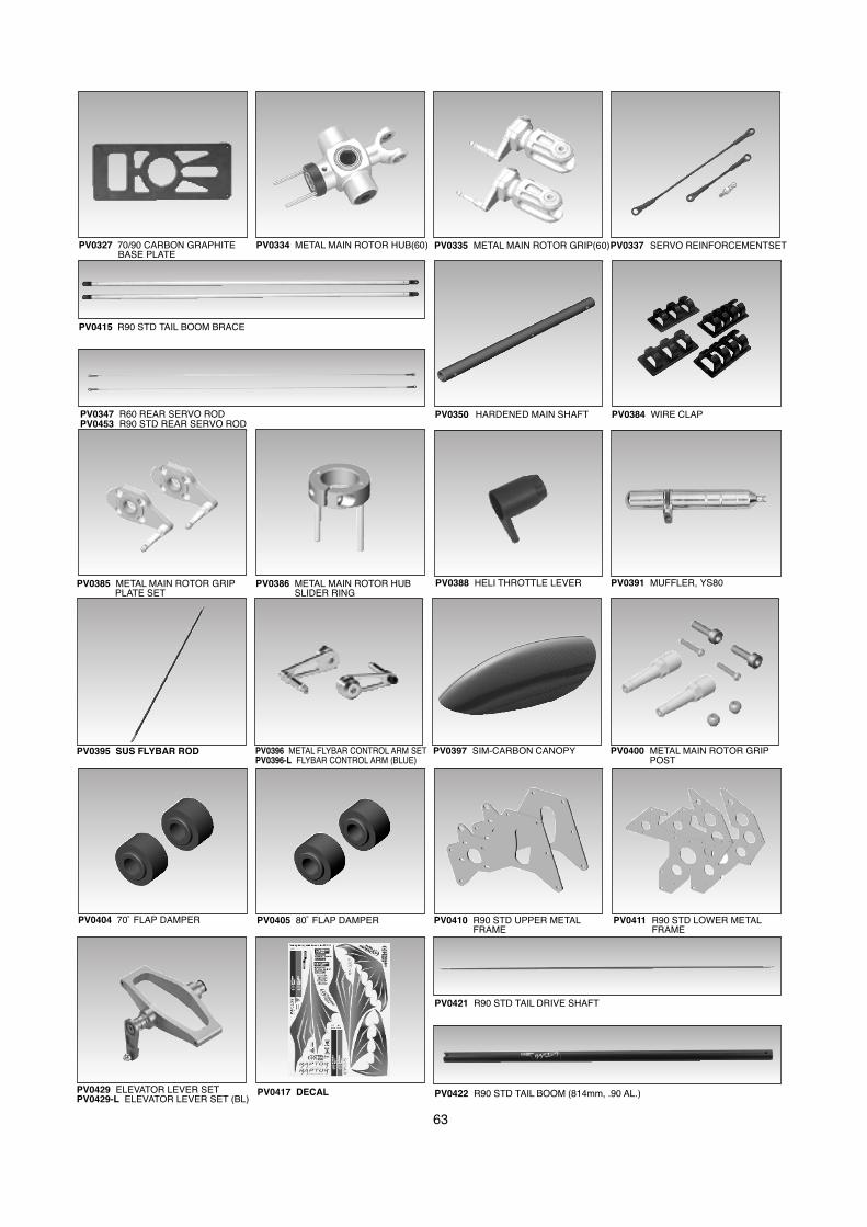
63
PV0422 R90 STD TAIL BOOM (814mm, .90 AL.)
PV0421 R90 STD TAIL DRIVE SHAFT
PV0415 R90 STD TAIL BOOM BRACE
PV0347 R60 REAR SERVO RODPV0453 R90 STD REAR SERVO ROD
PV0327 70/90 CARBON GRAPHITE BASE PLATE
PV0337 SERVO REINFORCEMENTSET
PV0429 ELEVATOR LEVER SETPV0429-L ELEVATOR LEVER SET (BL)
αPV0410 R90 STD UPPER METALFRAME
PV0411 R90 STD LOWER METALFRAME
PV0404 70˚ FLAP DAMPER PV0405 80˚ FLAP DAMPER
PV0395 SUS FLYBAR ROD
PV0417 DECAL
PV0335 METAL MAIN ROTOR GRIP(60)PV0334 METAL MAIN ROTOR HUB(60)
PV0384 WIRE CLAP
PV0388 HELI THROTTLE LEVER
PV0397 SIM-CARBON CANOPY
PV0385 METAL MAIN ROTOR GRIPPLATE SET
PV0386 METAL MAIN ROTOR HUBSLIDER RING
PV0400 METAL MAIN ROTOR GRIPPOST
PV0350 HARDENED MAIN SHAFT
PV0396 METAL FLYBAR CONTROL ARM SETPV0396-L FLYBAR CONTROL ARM (BLUE)
PV0391 MUFFLER, YS80
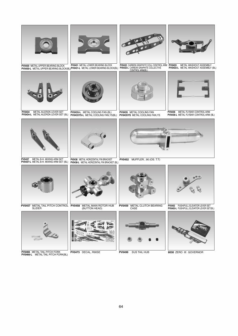
64
PV0430 METAL UPPER BEARING BLOCKPV0430-L METAL UPPER BEARING BLOCK(BL)
PV0434 METAL AILERON LEVER SETPV0434-L METAL AILERON LEVER SET (BL)
PV0432 CARBON GRAPHITE COLL CONTROL ARMPV0432-L CARBON GRAPHITE COLLECTIVE
CONTROL ARM(BL)
PV0433 METAL WASHOUT ASSEMBLYPV0433-L METAL WASHOUT ASSEMBLY (BL)
PV0435-L METAL COOLING FAN (BL)PV0435YS-L METAL COOLING FAN,YS(BL)
PV0431 METAL LOWER BEARING BLOCKPV0431-L METAL LOWER BEARING BLOCK(BL)
PV0435 METAL COOLING FANPV0435YS METAL COOLING FAN,YS
PV0436 METAL FLYBAR CONTROL ARMPV0436-L METAL FLYBAR CONTROL ARM (BL)
PV0437 METAL B-H. MIXING ARM SETPV0437-L METAL B-H. MIXING ARM SET (BL)
8030 ZERO α GOVERNORPV0499 SUS TAIL HUBPV0473 DECAL, R90SE
PV0438 METAL HORIZONTAL FIN BRACKETPV0438-L METAL HORIZONTAL FIN BRACKET (BL)
PV0452 MUFFLER, .90 (OS. T.T)
PV0457 METAL TAIL PITCH CONTROLSLIDER
PV0458 METAL MAIN ROTOR HUB(BUTTON HEAD)
PV0459 METAL CLUTCH BEARINGCASE
PV0463 PUSH/PULL ELEVATOR LEVER SETPV0463-L PUSH/PULL ELEVATOR LEVER SET(BL)
PV0466 METAL TAIL PITCH FORKPV0466-L METAL TAIL PITCH FORK(BL)