unimaster uma 450 dust collectors - donaldson.com · quick-release sealer gear dust container...
TRANSCRIPT
Donaldson reserve the right to alter design without notice.
Data Sheet
Unimaster Dust CollectorsSeries UMA 450
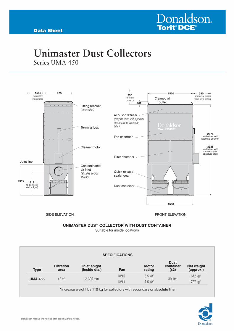
Lifting bracket(removable)
Terminal box
Acoustic diffuser (may be fitted with optional secondary or absolute filter)
Fan chamber
Cleaned air outlet
Joint lineFilter chamber
Quick-release sealer gear
Dust container
Cleaner motor
Contaminated air inlet (at sides and/or at rear)
975
1040
1550230
102
1520
1583
2875(collectors with
acoustic diffuser)
812(to centre of inlet spigot)
3335(collectors with secondary or absolute filter)
380required for maintenance minimum
clearance
required for cleaner motor cover removal
SIDE ELEVATION FRONT ELEVATION
UNIMASTER DUST COLLECTOR WITH DUST CONTAINERSuitable for inside locations
SPECIFICATIONS
TypeFiltration
areaInlet spigot (inside dia.) Fan
Motor rating
Dust container
(x2)Net weight (approx.)
UMA 456 42 m2 Ø 305 mmKV10 5.5 kW
80 litre672 kg*
KV11 7.5 kW 737 kg*
*Increase weight by 110 kg for collectors with secondary or absolute filter

2
Data Sheet
Unimaster Dust Collectors – Series UMA 450
Lifting bracket (removable)
Terminal box
Acoustic diffuser (may be fitted with optional secondary or absolute filter)
Fan chamber
Filter chamberCleaner motor
230975 1520
757 413
812
1550
minimum clearance
required for maintenance
380
102
required for cleaner motor cover removal
1835(collectors with
acoustic diffuser)
2295(collectors with secondary or absolute filter)
s e a t i n g l e v e l
UNIMASTER HOPPER TYPE DUST COLLECTORSuitable for inside locations
POSITION OF REAR CONTAMINATED AIR INLETS
SPECIFICATIONS
TypeFiltration
area FanMotor rating
Net weight (approx.)
UMA 450H 42 m2KV10 5.5 kW 537 kg*
KV11 7.5 kW 568 kg*
*Increase weight by 110 kg for collectors with secondary or absolute filter
SIDE ELEVATION FRONT ELEVATION
REAR ELEVATION
413
Cleaned air outlet

3
Data Sheet
Unimaster Dust Collectors – Series UMA 450
Lifting bracket (removable)
Lifting bracket (removable)
Filter chamber
Filter chamber
Quick-release sealer gear
Dust container
Cleaner motor
Cleaner motor
Contaminated air inlet(at sides and/or at rear)
230975 1520
875
1520975
1040
1915
1583
380
960
minimum clearance
required for maintenance
380
81
required for cleaner motor cover removal
required for cleaner motor cover removal
s e a t i n g l e v e l
UNIMASTER VENTING TYPE DUST COLLECTORSuitable for inside locations and outside when fitted with optional weather cowl
UNIMASTER VENTING TYPE DUST COLLECTOR WITH DUST CONTAINERSSuitable for inside locations and outside when fitted with optional weather cowl
SPECIFICATIONS
TypeFiltration
areaInlet spigot (inside dia.)
Dust container
(x2)Net weight (approx.)
UMA 456V 42 m2 Ø 305 mm 80 litre 414 kg*
*Increase weight by 45 kg for collectors with weather cowl
SPECIFICATIONS
TypeFiltration
areaNet weight (approx.)
UMA 450V 42 m2 279 kg*
*Increase weight by 45 kg for collectors with weather cowl
SIDE ELEVATION
SIDE ELEVATION
FRONT ELEVATION
FRONT ELEVATION
Cleaned air outlet
Cleaned air outlet
230minimum clearance
81
960required for maintenance
812to centre of inlet spigot
Joint line

4
Data Sheet
Unimaster Dust Collectors – Series UMA 450
CLEANED AIR OUTLET DETAILS
Standard and Hopper type colllectors Venting type colllectorsAll holes Ø 3.5 mm. Pitch centres: 100 mm.
APERTURE AND MOUNTING FLANGE DETAILS FOR HOPPER AND VENTING TYPE COLLECTORSAll holes Ø12 mm for M10 bolts
558 228 228
38.5
38.5
300
46
909090
16.5
16
911
1517
1583
3333
977
4040 40
33
90
33
40
90
90
135
4 pitches @133 mm
2 pitches @137 mm
2 pitches @137 mm
4 pitches @133 mm
428
200
347
200 2929
295= =117
327
56.5

5
Data Sheet
Unimaster Dust Collectors – Series UMA 450
FAN SELECTION
These curves indicate static pressure available at fan inlet for a given volume when fitted inside a Unimaster dust collector.
To select the most suitable fan for a given application:
1 Determine the air volume, in m3/h, needed to entrain the dust.
2 Read off the unit resistance, in mm W.G., at air volume required.
3 Assess pressure drop over filter bags prior to cleaning, usually 50 to 100 mm W.G.
4 Estimate pressure drop through connected system − i.e. between point of entrainment and collector inlet.
5 The sum of 2, 3 and 4 = W.G. required.
6 Consult graph for fan performances available.
NOISE LEVELS
Machinery noise levels are an important consideration in the design and selection of new equipment. Several EC Directives and National Laws/Regulations adopting these directives make reference to airborne noise emissions.
Actions that employers are required to comply with if employees are subjected to a daily personal noise exposure Lep,d of 80 dB(A) or more are also specified.
All Unimaster dust collectors, when fitted with an acoustic diffuser, secondary filter or absolute filter, operating an 8 hour shift, are below this action limit.
WEIGHTED SOUND PRESSURE LEVELS
All readings were taken in normal industrial areas, i.e. semi-reverberant surroundings, with local equipment silent.Measurements were taken at maximum air flow conditions at 1.0 metre radius from the equipment housing
and 1.6 metres above base level, using a precision sound level meter and octave filter.
KV10 KV11
74 dB(A)* 76dB(A)
Noise levels of installed equipment may vary due to site conditions. *Estimated data.
UNIT PERFORMANCE CURVES

6
Data Sheet
Unimaster Dust Collectors – Series UMA 450
DUST CONTAINER
Typical dust densities
80 litre(3 cu.ft.)
SizeApprox. net
weight DustDensity with 50%
voidage
80 litre 6 kg Sander 0.13 kg/litreGraphite 0.80 kg/litreSand 1.33 kg/litreIron 3.58 kg/litreSteel 3.72 kg/litre
A reasonable total load forremoval by hand would be 25 kg
ELECTRICAL REQUIREMENTS
UCS Controller
Voltage input: 380-420V, Three Phase, 50Hz
440-480V, Three Phase, 60Hz
or to suit local voltage
DESIGN LIMITS (standard equipment)
Temperature range: -10° to +60°C
Pressure limits: Collecters with fan: As fan performance curves from shut-off to operating pressure
Venting type collectors: -300 mm W.G. to +250 mm W.G.
Dimension tolerances: ±3 mm on main dimensions; ±2 mm on detail dimensions
OPTIONAL WEATHER COWL
SIDE ELEVATION
(Detail of cleaned air outlet with weather cowl and lid removed)
SIDE ELEVATION FRONT ELEVATION
230
229
27.5 27.5 75 194
402
30
1541920
155
984
minimum clearance

7
Data Sheet
Unimaster Dust Collectors – Series UMA 450
REAR ELEVATION SIDE ELEVATION
100
114all units
Joint line
POSITION OF OPTIONAL EXPLOSION RELIEF FLANGEIf a vent duct is not connected to the explosion relief flange, then a minimum clearance of 500 mm should be made to the rear of the collector to ensure efficient operation of the explosion venting process. Consideration should be given to the
local surrounding area in regards to the pressure and flame effects.
OPTIONAL EXPLOSION RELIEF FLANGE MOUNTING DETAILSAll holes Ø10 mm for M8 bolts
57
40
40
4040
53
53
57
666
1424
4 pitches @ 150 mm
9 pitches @ 150 mm
1504
746
20
20

Donaldson Southeast AsiaTel: +65 6349 8168Website: www.asia.donaldson.com
Donaldson USATel: +1 800 365 1331Website: www.donaldsontorit.com
Donaldson EuropeTel: +32 16 383 811Website: www.donaldson.com
Donaldson JapanTel: +81 42 540 4114Website: www.donaldson.co.jp
Donaldson KoreaTel: +82 251 733 33Website: www.donaldson.co.kr
Donaldson South AsiaTel: +91 124 480 7536Website: www.india.donaldson.com
Donaldson Australasia
Website: www.donaldsonfilters.com.au
Donaldson ChinaTel: 400 820 1038 Website: www.donaldson.cn
www.donaldson.com
Data Sheet
Unimaster Dust Collectors – Series UMA 450