uniform nanostructured arrays of sodium rare-earth fluorides for highly efficient multicolor...
TRANSCRIPT

Hydrothermal SynthesisDOI: 10.1002/ange.200702519
Uniform Nanostructured Arrays of Sodium Rare-Earth Fluorides forHighly Efficient Multicolor Upconversion Luminescence**Fan Zhang, Ying Wan, Ting Yu, Fuqiang Zhang, Yifeng Shi, Songhai Xie, Yigang Li, Lei Xu,Bo Tu, and Dongyuan Zhao*
Upconversion (UC) phosphors emit high-energy photonswhen they are excited by low-energy photons. This property isattractive for flat-panel displays,[1,2] optical storage,[3] bio-labels,[4] solid-state lasers,[5] and light-emitting diodes.[6] HighUC luminescence efficiency is typically generated by bulkmaterials[1] and colloidal nanocrystals[7] of hexagonal-phaselanthanide-doped rare-earth fluorides, but nanoarrays ofsingle crystals are more desirable for solid-state lasers. TheUC luminescence efficiency can be enhanced if the nano-arrays are aligned with photonic-crystal microstructures, andthe faceted end planes of well-shaped crystals serve as goodlaser-cavity mirrors.[8]
Herein, we report a general solution-based approach forthe preparation of uniform nanostructured arrays of thesodium rare-earth (M) fluorides NaMF4. The arrays can beprepared with well-controlled morphologies (tubes, disks, orrods), phases (cubic or hexagonal), sizes (80–900 nm), andcompositions. This approach avoids the assistance of tem-plates, applied fields, and undercoating on substrates,[9,10] andis industrially feasible, owing to its ease and low cost.Multicolor UC fluorescence is also generated when thenanoarrays are pumped in the near-infrared (NIR) region;for example, green or blue fluorescence is produced fornanoarrays of NaYF4 codoped with Yb3+ and Er3+, or Yb3+
and Tm3+, respectively. Owing to their unique luminescence
and chemical flexibility, these nanoarrays offer great potentialas light sources for miniaturized solid-state lasers.
The nanostructured arrays of NaMF4 were prepared by afacile hydrothermal approach, using oleic acid as a stabilizingagent, and NaF and M(NO3)3 as precursors, in the temper-ature range of 130–230 8C under basic conditions (for detailssee the Supporting Information). The products are composedof uniformly hexagonal nanotubes with outer diameters ofabout 250 nm and lengths of about 500 nm, as shown byscanning electron microscopy (SEM) (Figure 1a).
Energy-dispersive X-ray (EDX) analyses of the productsobtained using Y(NO3)3 as a precursor revealed that thenanotubes have a molar Na/Y/F ratio of 1.0:1.0:4.0, demon-strating the formation of stoichiometric NaYF4 (see Figure S1in the Supporting Information). Owing to their homogeneity,these tubes could pack into ordered hexagonal arrays(Figure 1b). Inside the hexagonal tubes are wedge-shapedinstead of channel structures, as confirmed by transmissionelectron microscopy (TEM) (Figure 1c). Electron diffraction(ED) patterns taken from top/bottom surfaces and side facesof the tubes could be indexed as {0001} and {11̄00} planes,respectively, of hexagonal b-NaYF4 (space group P63/mmc ;Figure 1c, inset). The nanotubes grow along the [0001]direction, owing to the aspect ratio of the cell parameters.High-resolution (HR) TEM images show interplanar spacings
Figure 1. a),b) SEM images of arrays of hexagonal nanotubes ofb-NaYF4. c) TEM image of the nanotubes and corresponding EDpatterns (insets). d) HRTEM image of a nanotube.
[*] F. Zhang, T. Yu, Dr. F. Q. Zhang, Dr. Y. F. Shi, Dr. S. H. Xie, Dr. B. Tu,Prof. Dr. D. Y. ZhaoLaboratory of Advanced MaterialsShanghai Key Laboratory of Molecular Catalysis and InnovativeMaterialsDepartment of ChemistryFudan University, Shanghai 200433 (China)Fax: (+ 86)21-5566-4192E-mail: [email protected]: http://homepage.fudan.edu.cn/~dyzhao/default.htm
Dr. Y. WanDepartment of ChemistryShanghai Normal University, Shanghai 200234 (China)
Dr. Y. G. Li, Prof. Dr. L. XuDepartment of Optical Science and EngineeringFudan University, Shanghai 200433 (China)
[**] This work was supported by the NSF of China (20421303 and20521140450), the State Key Basic Research Program of China(2006CB202502 and 2006CB0N0302), the Shanghai Science andTechnology Committee (06DJ14006, 055207078, and 05DZ22313),and the Shanghai Nanotech Promotion Center (0652nm024). Wethank J. Shan, D. R. Wang, H. Y. Chen, and Y. Chen for assistancewith the characterization.
Supporting information for this article is available on the WWWunder http://www.angewandte.org or from the author.
Zuschriften
8122 � 2007 Wiley-VCH Verlag GmbH & Co. KGaA, Weinheim Angew. Chem. 2007, 119, 8122 –8125

of 0.52 and 0.35 nm corresponding to the {101̄0} and {0001}planes of b-NaYF4, respectively (Figure 1d).
An important feature of the nanotubes is that theirconcave surface also possesses a sixfold structure associatedwith the crystal symmetry. X-ray diffraction (XRD) patternsfurther indicate that the nanotubes obtained after heating at230 8C for 12 h consist of pure b-NaYF4 (Figure S2).
The XRD patterns demonstrate that the productsobtained with lower NaOH concentrations remain nano-crystals of b-NaYF4 (Figure S3). SEM images reveal that theproducts obtained by decreasing the concentration of NaOHto some extent consist of fairly uniform disks with diametersof about 800 nm and thicknesses of about 300 nm (Figure 2a),which close pack into nanoarrays in some domains (Fig-ure 2b). All the disks feature flower-like patterns, with a
sixfold axis, on their tops and bottoms. Careful statisticalmeasurements reveal that the rotary direction of the flowerpatterns is random. The number of disks with left-handedpatterns is equal to that with right-handed patterns. Forindividual disks, only one rotary direction is observed in TEMimages (Figure 2c and Figure S4a), which indicates that thetop and bottom faces of the disks have opposite rotationpatterns. This result may explain the even distribution ofright- and left-handed patterns (Figure 2d). The side faces ofthe disks exhibit a well-faceted quasirhombic morphology(Figure 2a,b,d and Figure S4b). ED patterns verify that thehexagonal disks are single crystals of the b-NaYF4 structure
with {0001} top/bottom surfaces and {11̄00} side faces(Figure 2c, inset, and Figure S4c,d). The {1000} lattice fringeestimated from an HRTEM image is 0.52 nm (Figure 2e), ingood agreement with the value of 0.52 nm calculated fromXRD data (Figure S3).
At higher NaF concentrations, nanorods of b-NaYF4 canbe obtained. SEM and TEM images show that these nanorodshave uniform diameters of about 110 nm and lengths of about2 mm (Figure 2 f,g). The same b-NaYF4 structure as for thenanotubes and disks was detected for the nanorods by XRD,HRTEM, and ED analyses. Again, the top/bottom surfacescould be indexed as {0001} planes and the side faces as {11̄00}planes (Figure 2g, inset, and Figure S5). The intensity of the100 diffraction peak in the XRD pattern is relatively high,consistent with preferential growth along the [0001] direction.
Temperature and time of the hydrothermal reactiongreatly influence the final products. A mixture of the cubica-NaYF4 (space group Fm3̄m) phase and the hexagonalb-NaYF4 phase was obtained after hydrothermal reaction at230 8C for 1 h, as shown in the XRD pattern of the products(Figure S6 in the Supporting Information). TEM images andED patterns, indeed, show both large cylindrical particles ofthe hexagonal phase and small nanocrystals of the cubic phase(Figure S7 in the Supporting Information). Prolonging thereaction time (3–24 h) results in the formation of increasingamounts of hexagonal nanotubes and eventually yields pureb-NaYF4. Nanocrystals of cubic a-NaYF4 with diameters ofabout 5 nm are formed at a low temperature of 130 8C(Figure S2 and Figure S8). Increasing the reaction temper-ature leads to a phase transformation from a- to b-NaYF4
(Figure S2 in the Supporting Information).The phase and morphology of the products can also be
tuned by adjusting the composition of the reaction mixture.With an increase in the oleic acid/NaOH ratio, a phasetransformation from the cubic phase to the hexagonal phaseoccurs as well. Under these conditions, a short reaction time(9 h) results in flower-patterned disks of b-NaYF4 withunclear rotary directions and very small side faces(Figure S9a). Comparison with the disks obtained after a12-hour hydrothermal treatment, which have distinct rotarydirections, suggests that the rotary direction is generated fromcompetition between the [0001] and [011̄0] directions in thegrowth of the {11̄00} side faces. Further growth of the sidefaces along the [0001] direction leads to the dislocation of theflower-pattern ends. When the concentration of Y3+ (withY3+/F� constant at 1:4) increases from 0.2 to 0.8 to 1.6 mm, theouter diameter of the b-NaYF4 nanotubes increases from 80to 200 to 500 nm (Figure S9b–d). The present synthesisapproach is general and can produce nanoarrays of hexagonalNaMF4 phases with other rare earths, such as NaErF4,NaTmF4, NaYbF4, and NaLuF4 (Figure S10).
We speculate that the formation of NaYF4 is related to adissolution–reconstruction process (Figure 3),[11] in whicha-NaYF4 is a metastable phase, and the transformation froma- to b-NaYF4 is irreversible. The reaction system could bedescribed with a model of microemulsion and reverse micelles(Figure 3). The sodium oleate generated from oleic acid andNaOH forms reverse micelles containing Y3+ ions. Thesereverse micelles, together with NaF, oleic acid, and water,
Figure 2. a),b) SEM images of arrays of flower-patterned hexagonaldisks of b-NaYF4. c) TEM image of the disks and corresponding EDpattern (inset). d) Illustration of the {0001} top/bottom faces and the{11̄00} side faces of a disk. e) HRTEM image of a corner of a disk.f) SEM image of arrays of hexagonal nanorods of b-NaYF4. g) TEMimage of the nanorods and corresponding ED pattern (inset).
AngewandteChemie
8123Angew. Chem. 2007, 119, 8122 –8125 � 2007 Wiley-VCH Verlag GmbH & Co. KGaA, Weinheim www.angewandte.de
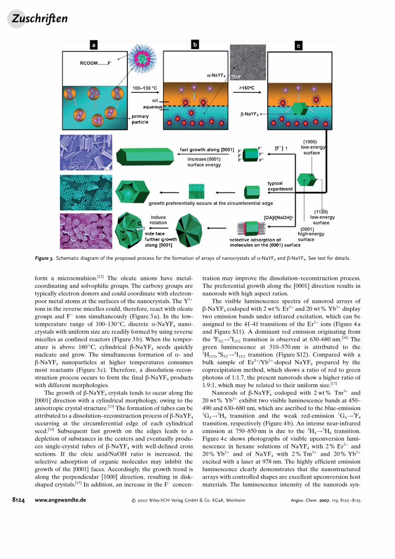
form a microemulsion.[12] The oleate anions have metal-coordinating and solvophilic groups. The carboxy groups aretypically electron donors and could coordinate with electron-poor metal atoms at the surfaces of the nanocrystals. The Y3+
ions in the reverse micelles could, therefore, react with oleategroups and F� ions simultaneously (Figure 3a). In the low-temperature range of 100–130 8C, discrete a-NaYF4 nano-crystals with uniform size are readily formed by using reversemicelles as confined reactors (Figure 3b). When the temper-ature is above 160 8C, cylindrical b-NaYF4 seeds quicklynucleate and grow. The simultaneous formation of a- andb-NaYF4 nanoparticles at higher temperatures consumesmost reactants (Figure 3c). Therefore, a dissolution–recon-struction process occurs to form the final b-NaYF4 productswith different morphologies.
The growth of b-NaYF4 crystals tends to occur along the[0001] direction with a cylindrical morphology, owing to theanisotropic crystal structure.[13] The formation of tubes can beattributed to a dissolution–reconstruction process of b-NaYF4
occurring at the circumferential edge of each cylindricalseed.[14] Subsequent fast growth on the edges leads to adepletion of substances in the centers and eventually produ-ces single-crystal tubes of b-NaYF4 with well-defined crosssections. If the oleic acid/NaOH ratio is increased, theselective adsorption of organic molecules may inhibit thegrowth of the {0001} faces. Accordingly, the growth trend isalong the perpendicular [1000] direction, resulting in disk-shaped crystals.[15] In addition, an increase in the F� concen-
tration may improve the dissolution–reconstruction process.The preferential growth along the [0001] direction results innanorods with high aspect ratios.
The visible luminescence spectra of nanorod arrays ofb-NaYF4 codoped with 2 wt% Er3+ and 20 wt% Yb3+ displaytwo emission bands under infrared excitation, which can beassigned to the 4f–4f transitions of the Er3+ ions (Figure 4aand Figure S11). A dominant red emission originating fromthe 4F9/2!4I15/2 transition is observed at 630–680 nm.[16] Thegreen luminescence at 510–570 nm is attributed to the2H11/2,
4S3/2!4I15/2 transition (Figure S12). Compared with abulk sample of Er3+/Yb3+-doped NaYF4 prepared by thecoprecipitation method, which shows a ratio of red to greenphotons of 1:1.7, the present nanorods show a higher ratio of1.9:1, which may be related to their uniform size.[17]
Nanorods of b-NaYF4 codoped with 2 wt% Tm3+ and20 wt% Yb3+ exhibit two visible luminescence bands at 450–490 and 630–680 nm, which are ascribed to the blue-emission1G4!3H6 transition and the weak red-emission 1G4!3F4
transition, respectively (Figure 4b). An intense near-infraredemission at 750–850 nm is due to the 3H4!3H6 transition.Figure 4c shows photographs of visible upconversion lumi-nescence in hexane solutions of NaYF4 with 2% Er3+ and20% Yb3+ and of NaYF4 with 2% Tm3+ and 20% Yb3+
excited with a laser at 978 nm. The highly efficient emissionluminescence clearly demonstrates that the nanostructuredarrays with controlled shapes are excellent upconversion hostmaterials. The luminescence intensity of the nanorods syn-
Figure 3. Schematic diagram of the proposed process for the formation of arrays of nanocrystals of a-NaYF4 and b-NaYF4. See text for details.
Zuschriften
8124 www.angewandte.de � 2007 Wiley-VCH Verlag GmbH & Co. KGaA, Weinheim Angew. Chem. 2007, 119, 8122 –8125

thesized with high F� concentrations is stronger than those ofthe tube and disk samples. This result may be related to thelarge amount of F� ions on the surface of the nanorods, whichcould prevent oxygen contamination.
These results illustrate the great potential of well-definednanoarrays of tubes and rods of b-NaYF4 for use in laser-cavity mirrors and laser media. The arrays of b-NaYF4
nanoparticles could shed light for the optical microdiskresonator, which could confine light to a small modalvolume by resonant recirculation with a low optical loss. Weconsider this an important step towards the development ofupconversion nanostructured materials with a great potential
for the development of miniature optoelectronics, in partic-ular in the fields of solid-state lasers, photonic crystals, opticalstorage, and waveguides.
Received: June 10, 2007Revised: July 16, 2007Published online: September 11, 2007
.Keywords: fluorides · hydrothermal synthesis · luminescence ·nanostructures · rare earth metals
[1] E. Downing, L. Hesselink, J. Ralston, R. Macfarlane, Science1996, 273, 1185.
[2] P. Lodahl, A. F. van Driel, I. S. Nikolaev, A. Irman, K. Overgaag,D. Vanmaekelbergh, W. L. Vos, Nature 2004, 430, 654.
[3] P. Cheben, F. del Monte, D. J. Worsfold, D. J. Carlsson, C. P.Grover, J. D. Mackenzie, Nature 2000, 408, 64.
[4] D. van de Rijke, H. Zijlmans, S. Li, T. Vail, A. K. Raap, R. S.Niedbala, H. J. Tanke, Nat. Biotechnol. 2001, 19, 273.
[5] G. Rumbles, Nature 2001, 409, 572.[6] M. Stockman, Nat. Mater. 2004, 3, 423.[7] G. S. Yi, H. C. Lu, S. Y. Zhao, G. Yue, W. J. Yang, Nano Lett.
2004, 4, 2191.[8] M. H. Huang, S. Mao, H. Feick, H. Q. Yan, Y. Y. Wu, H. Kind, E.
Weber, R. Russo, P. D. Yang, Science 2001, 292, 1897.[9] B. Z. Tian, X. Y. Liu, B. Tu, C. Z. Yu, J. Fan, L. M. Wang, S. H.
Xie, G. D. Stucky, D. Y. Zhao, Nat. Mater. 2003, 2, 159.[10] X. Wang, J. Zhuang, Q. Peng, Y. D. Li, Nature 2005, 437, 121.[11] J. W. Mullin, Crystallization, 3rd ed., Butterworth-Heinemann,
Oxford, 1997.[12] M. Li, H. Schnablegger, S. Mann, Nature 2000, 402, 393.[13] Y. W. Jun, J. S. Choi, J. Cheon, Angew. Chem. 2006, 118, 3492;
Chem. Int. Ed. 2006, 45, 3414.[14] B. Mayers, Y. N. Xia, Adv. Mater. 2002, 14, 279 – 282.[15] X. G. Peng, L. Manna, W. D. Yang, J. Wickham, A. P. Alivisatos,
Nature 2000, 404, 59.[16] F. Auzel, Chem. Rev. 2004, 104, 139.[17] R. H. Page, K. I. Schaffers, P. A. Waide, J. B. Tassano, S. A.
Payne, J. Opt. Soc. Am. B 1998, 15, 996.
Figure 4. UC luminescence spectra of b-NaYF4 codoped with a) 2 wt %Er3+ and 20 wt % Yb3+, or b) 2 wt % Tm3+ and 20 wt % Yb3+ (excitedwith a 978-nm laser diode; power density of 80 Wcm�2). c) Photo-graphs of the UC luminescence of 0.2 wt % (1) and 1 wt % (2) hexanesolutions of b-NaYF4 codoped with 2 wt % Er3+ and 20 wt % Yb3+, andof 0.2 wt % (3) and 1 wt % (4) hexane solutions of b-NaYF4 codopedwith 2 wt % Tm3+ and 20 wt % Yb3+ (excited with a 978-nm laser diode;laser power of 800 mW).
AngewandteChemie
8125Angew. Chem. 2007, 119, 8122 –8125 � 2007 Wiley-VCH Verlag GmbH & Co. KGaA, Weinheim www.angewandte.de