underthrusting-accretion cycle: work budget as revealed by
TRANSCRIPT

Underthrusting-accretion cycle: Work budget as revealed
by the boundary element method
Mario Del Castello1 and Michele L. Cooke1
Received 16 February 2007; revised 3 August 2007; accepted 20 September 2007; published 29 December 2007.
[1] Sandbox models of accretionary wedges have demonstrated that fault systems growepisodically via cycles of alternating wedge thickening, which is accommodated by slipalong faults within the wedge (underthrusting), and wedge lengthening, which isaccommodated by growth of new faults at the wedge toe (accretion). The transitionbetween these two modes of deformation is controlled by the interplay of work againstgravity, frictional heating, the work of deformation around faults, and the work offault propagation and seismic/acoustic energy. Using numerical mechanical models basedon the boundary element method, we have simulated the deformation observed in sandboxexperiments, providing a mechanical analysis of the underthrusting/accretiontransition. Our results show that the total work done by the contracting wedge increasesduring the underthrusting stage up to a critical value when the propagation of a new frontalthrust significantly reduces the work required for further deformation. The numericalmodels also predict the location of the maximum shear along the basal decollement duringunderthrusting as well as the energetically most viable position and vergence for thenucleation of a new thrust. These locations do not coincide, and the match of theenergetically most favorable position with the experimental results suggests that the newthrust ramps develop first ahead and then link down and backward to the propagatingbasal decollement. The shear localization producing a new thrust ramp will occurwhere the energy spent by the deforming wedge is minimized due to an optimalcombination of gravitational, frictional, internal, and propagation work terms.
Citation: Del Castello, M., and M. L. Cooke (2007), Underthrusting-accretion cycle: Work budget as revealed by the boundary
element method, J. Geophys. Res., 112, B12404, doi:10.1029/2007JB004997.
1. Introduction
1.1. Critical Taper Theory
[2] Since the proposition of the critical taper theory[Dahlen et al., 1984; Dahlen, 1990], fold and thrust beltshave been successfully analyzed with the assumption thatthey deform as a self-similar wedge of noncohesive brittlematerial such as in front of an advancing bulldozer. Thetheory states that the wedge deformation is ultimatelycontrolled by the ratio between internal coefficient offriction (m) and the basal coefficient of friction (mb) andthat the wedge must be on the verge of Coulomb failureeverywhere and at every time. Only in this case can thetaper angle be calculated as a function of m and mb [Dahlen,1990]. The requirements set in the analytical treatmentproduce a constant taper angle during wedge growth, i.e.,the wedge preserves a fixed length to height ratio through-out deformation. However, this reflects observations only toa first degree.[3] The critical taper theory has been largely applied to
the evolution of fold and thrust belts since its proposition
and systematically tested against both natural analogues[Lallemand et al., 1994; Ford, 2004; Bangs et al., 2004;Vannucchi et al., 2003; Saffer and Bekins, 2006; Wang andHu, 2006] and experimental techniques [Bombolakis, 1994;Lohrmann et al., 2003; Adam et al., 2005]. The wideapplication of the theory of critical taper owes to itsintuitively simple approach to interpret wedge mechanicsin terms of m/mb ratio, despite the complexity of theanalytical treatment. By simply reducing or increasing theaforementioned ratio, the equations derived for this theorysuccessfully predict the complete sequence of faultingprocesses occurring at contractional margins (accretion,underthrusting, underplating and basal erosion). Neverthe-less, the current form of the critical taper theory provides anend-member scenario that neglects the importance of elasticprocesses and strain hardening/softening that might affectthe temporal distribution of the state of stress and ultimatelythe wedge geometry [Wang and Hu, 2006]. For instance, thetheory correctly envisages transition between accretion andunderthrusting, but does not address why a wedge shouldactivate a deeper decollement level nor where shear stresseswould localize in order to produce a new fore-thrust ramp.Furthermore, the predicted constant taper is seldom ob-served in natural case studies. Rather than growing self-similarly, new material is generally seen to be incorporated
JOURNAL OF GEOPHYSICAL RESEARCH, VOL. 112, B12404, doi:10.1029/2007JB004997, 2007ClickHere
for
FullArticle
1Geosciences Department, University of Massachusetts, Amherst,Massachusetts, USA.
Copyright 2007 by the American Geophysical Union.0148-0227/07/2007JB004997$09.00
B12404 1 of 14

into the wedge episodically via processes that occur atdistinct times.[4] Elastic effects related to subduction megathrust faults
locking are well known to influence the large-scale geom-etry of the forearc. Zones of interseismic locking may act asboundaries between subsiding basins and accreting regions[Wells et al., 2003] and control variations in trench-parallelforearc topography [Song and Simons, 2003], such assteepening of the forearc slope [Bangs et al., 2004]. Alsorotations of large-scale sectors of orogens have been attrib-uted to plate locking [McCaffrey et al., 2000]. However,how the role of local elastic processes that operate on singlethrust fault might influence the wedge mechanics has notyet been investigated in detail.
1.2. Overview of Sandbox Experiments of WedgeGrowth
[5] Sandbox models are a common technique to studywedge kinematics. Analysis of analogue experiments sug-gest that the wedge development is characterized by dis-continuous phases of alternating wedge thickening,accommodated by slip along thrust faults within the wedge,and wedge lengthening, accommodated by nucleation ofnew thrust faults in front of the wedge [e.g., Mulugeta andKoyi, 1992; Storti and McClay, 1995; Gutscher et al., 1996;McClay and Whitehouse, 2004; Konstantinovskaia andMalavieille, 2005]. These two processes are referred to asunderthrusting and accretion. After an early phase ofaccretion (Figure 1a), an underthrusting stage begins, whena coherent sheet of undeformed material slides underneath
the wedge via activation of a roof thrust. The roof thrustallows for the wedge to vertically thicken, increasing thetaper angle (Figure 1b). By contrast, the accretionary stagepredicts nucleation of new thrust ramps in front of the toe ofthe wedge by concentrating the slip along the basal decolle-ment. New fore thrusts accrete at the wedge front and thewedge taper decreases accordingly (Figure 1c). Recentanalyses showed the cyclic nature of this transition[Gutscher et al., 1998; Del Castello et al., 2004; Adam etal., 2005; Naylor et al., 2005]. As a result of these cyclicprocesses, the wedge may display a variety of slope anglesduring growth and does not obey the self-similar growthrequirement of critical taper theory. What controls theduration in time and the persistence of the accretion andunderthrusting stages? Observation of wedge growth insand-box models suggests that the predominance of onemode over the other can be controlled by such factors assyntectonic erosion/sedimentation or temporarily unbal-anced topography [Storti and McClay, 1995; Del Castelloet al., 2004], high basal friction [Gutscher et al., 1996;Kukowski et al., 2002; Konstantinovskaia and Malavieille,2005], wedge thickening and basal friction [Burbidge andBraun, 2002], mechanical interaction between prowedgeand retrowedge [Del Castello et al., 2004; Naylor et al.,2005]. Yet, all these approaches envisage static m/mb ratiowith faults in constant state of creep. In contrast, naturalfaulting processes incur friction drop during slip (i.e., slipweakening) that can change the mechanics of the system.Consequently, previous studies underestimate or totallyneglect the effect of the phases of elastic loading predatingepisodes of frictional slip on faults.[6] Stick-slip behavior [e.g., Rabinowicz, 1958] has been,
until recently, disregarded in analogue modeling of accre-tionary wedges, because of the general assumption that sandcannot preserve a ‘‘mechanical’’ memory on preexistingfractures. Because of the poor measurements of analogmaterial properties, the elastic interval of deformation andstrain hardening processes have been traditionally consid-ered as of secondary importance for noncohesive wedgegrowth. Recent refined laboratory analyses demonstrate thatgranular analogue materials show a significant departurefrom the Coulomb elastoperfectly plastic behavior, with amarked decrease in m at the transition between material peakstrength and residual strength [Lohrmann et al., 2003; Elliset al., 2004; Panien et al., 2006]. The strain hardening priorto peak strength and the strain softening post peak strengthhas been related to decompaction/compaction cycles affect-ing the sand during the compressional stress loading andsubsequent rupturing [Lohrmann et al., 2003]. The stress-strain curves for the sand materials tested agree well withcharacteristic curves of rocks and soils [Jaeger and Cook,1969; Lambe andWhitman, 1969;Marone, 1998; Barnhoornet al., 2004]. Adam et al. [2005] used particle imagingvelocimetry (PIV) techniques within sandbox experimentsof wedge growth to document how accretion and under-thrusting processes are not synchronous but cyclic and mightbe related to strain hardening/softening cycles occurring atthe roof thrust and basal decollement.[7] In this paper we use a boundary element method
(BEM) code to numerically reproduce the sandbox exper-iment of wedge deformation published by Adam et al.[2005]. Analogue models based on noncohesive, Coulomb
Figure 1. Schematic diagram illustrating two sequentialcycles of underthrusting-accretion. (a) Initial accretion. (b)Episodic deactivation of the basal decollement causesunderthrusting under the roof thrust (white arrows). (c)Nucleation of a new fore thrust that steps the wedge toeforward. Continuous thick lines indicate active faultsegments. Insets in Figures 1b and 1c show transitoryincrease/decrease of taper angle during underthrusting andaccretion phases, respectively.
B12404 DEL CASTELLO AND COOKE: UNDERTHRUSTING-ACCRETION WORK BUDGET
2 of 14
B12404

material are excellent tools to test the applicability of thecritical taper theory, yet their information is limited tokinematics rather than a full mechanical deformation. Wetry to bridge this gap by constructing a numerical model thatutilizes recently revisited strain hardening/softening proper-ties of sand within a fully elastic BEM code. The investi-gation is restricted to a single underthrusting/accretiontransition for which we calculate the work balance anddiscriminate between different work terms, trying to assessboth the trade-off mechanisms between the energy termsand the impact of each of them at the transition. The setupof our numerical models is based on the fault configurationsand sequence of faulting revealed by PIV analysis ofsandbox experiments by Adam et al. [2005]. This paperpresents a systemic view of wedge growth using workbudget assessments that are consistent with natural andsandbox observations, encompasses existing ideas of wedgegrowth and does not rely on temporal nor spatial variationsin material properties to achieve cyclic transitions betweenunderthrusting and accretion modes.
2. Work Analysis by Boundary Element Method
2.1. Description of Work Terms
[8] Transitions between underthrusting and accretionmodes may reflect adjustments to the balance between workagainst frictional slip along the basal and inner wedge faults,work of deformation within the host material and upliftwork against gravity. Despite the lack of consensus on theapplicability of the principle of work minimization to large-scale systems in nature [e.g., Bird and Yuen, 1979; Sleep etal., 1979], systemic analysis of the interaction betweenvarious work terms has yielded insights to the study ofdeformation mechanics of geological structures [Mitra andBoyer, 1986; Platt, 1988; Melosh and Williams, 1989;Gutscher et al., 1998; Masek and Duncan, 1998; Burbidgeand Braun, 2002]. However, studies to date have notrevealed the trade-off between the various work componentsas the system shifts between accretion and underthrustingmodes. Within accretionary systems, faults are constantlygrowing, shutting down and initiating via a complex inter-play of different work terms as the system persistently seeksto minimize the total work. The total work in thefault system, Wtot, is the sum of work against gravity, Wgrav,work against frictional sliding, Wfric, work of internaldeformation in the material around the fault, Wint, work ofpropagating new faults, Wprop, and work of seismic radiatedenergy, Wseis [Cooke and Murphy, 2004].
Wtot ¼ Wgrav þWfric þWint þWprop þWseis ð1Þ
Each of these work terms is calculated as the product ofappropriate force times displacement. The work againstgravity is positive for contractional systems and negative forextensional systems. Wgrav depends on the vertical upliftand vertical normal stress due to overburden weightintegrated over the area of the system. In a two-dimensionalsystem with horizontal position, x, and depth of burial, d, asa function of vertical position, z,
Wgrav ¼ZZ
rgd zð Þdxdz ð2Þ
where g is gravitational acceleration and r is the averagedensity of the overburden. When a fault slips, work is doneresisting friction along the fault surface; this work isexpressed as frictional heating. For example, weak faults(m = 0) produce no work against friction and do no exhibitfrictional heating.Wfric depends on fault slip and shear stressintegrated along the length of each fault in the system. Wfric
is one of several forms of work that is path-dependent.Faults do not necessarily unslip when they are unloaded sothat different loading paths may produce different Wfric.Consequently, this work is integrated over the loading path;in this case the path of applied horizontal strain, "hor. Wfric isalso integrated over the fault length, l, along which normalstress, sn, slip, s, and frictional coefficient, m, may vary.
Wfric ¼ZZ
sn "hor;l� �
m lð Þs "hor;l� �
d"hor;dl ð3Þ
The internal work is the stored strain energy density, ameasure of mechanical work within the system. Wint iscalculated as strain times stress at a point, integrated over thearea of the system [e.g., Timoshenko and Goodier, 1934].Using Hooke’s law, the strains can be formulated as stressesto get
Wint ¼ZZ
1� n2ð Þ2E
s2xx þ s2
zz
� �þ 1þ nð Þ
Es2xz þ nsxxszz
� �� �dzdx
ð4Þ
where E and v are the elastic properties Young’s modulusand Poisson’s ratio, respectively. The work of faultpropagation, based on Gibb’s free energy, is the energyrequired to break intact rock and create new fault surfaceenergy integrated over the length of new fault surfaces[Scholz, 2002]. Fault surfaces are often accompanied byabundant damage within the host rock so that the total newsurface area created is far greater than the area of new faultsurface. The seismic radiated energy, expressed as groundshaking or acoustic energy, is the energy released from thesurrounding rock during fault slip. Wseis is path-dependentand depends on the shear stress drop, Dt, and slip along thesliding faults [Scholz, 2002].
Wseis ¼ZZ
Dt "hor;l� �
s "hor;l� �
d"hor;dl ð5Þ
For finite models, such as that considered in this study, wecan also calculate external work on the system, which shouldequal the sum of the individual work terms. This externalwork is the product of displacement along the boundaries ofthe system times the forces along that boundary.Wext is path-dependent and is integrated over the loading path. Withinthis study we are able to compare the Wext from our modelsto Wtot in order estimate the errors in our work calculations.[9] Whereas some forms of work are nonconservative
and lost to the system such as Wfric, Wprop and Wseis, othersserve to store work that can be later used to drive faulting,Wgrav and Wint. For example, thrust faulting may releasestored internal strain within contracting systems, but thisoccurs at the expense of producing greater work againstgravity. Cooke and Murphy [2004] expanded the theoretical
B12404 DEL CASTELLO AND COOKE: UNDERTHRUSTING-ACCRETION WORK BUDGET
3 of 14
B12404

formulations of Mitra and Boyer [1986] to include a morerigorous internal work term (equation (4)) so that a com-pletely balanced work budget can be evaluated withinnumerical models to simulate the growth fault systems.We use this formulation (1) to evaluate the principle ofwork minimization theory for an accretion/underthrustingcycle, (2) to quantify the role of each work componentwithin a cycle, and (3) to test the similarity of analogexperiments to results obtained by the boundary elementmethod (BEM) technique.
2.2. BEM
[10] The BEM uses the principle of continuum mechanicsto calculate stress and strain throughout a faulted rock body[e.g., Crouch and Starfield, 1990]. All the data necessaryfor analysis of the work terms, including slip, traction,internal stress and strain and vertical displacements, areconstrained by the governing differential equations ofcontinuum mechanics. Unlike the Finite Element Method,which requires discretization of the entire body, the BEMonly requires discretization of model boundaries and dis-continuities (i.e., faults). This is advantageous for modelingmultiple interacting faults because BEM requires less effortfor discretization, and errors due to discretization andapproximation arise only on the boundaries and along faultsurfaces [Crouch and Starfield, 1990]. The BEM code usedin this study, FRIC2D, computes the two-dimensionalelastic and inelastic deformation associated with frictionalslip along faults using the displacement discontinuity for-mulation of Crouch and Starfield [1990] with specialconstitutive frictional-slip elements [Cooke and Pollard,1997]. The model boundaries and fault surfaces are dis-cretized into linear elements each with uniform shear andnormal displacement discontinuities. Additionally, alongfault surfaces FRIC2D requires prescription of constitutiveproperties such as cohesion and friction coefficient.FRIC2D has been used to investigate faulting [Cooke andPollard, 1997; Roering et al., 1997; Cooke and Kameda,2002; Cooke and Murphy, 2004], bedding plane slip withinfolds [Cooke et al., 2000], joint propagation [Cooke andUnderwood, 2001] and sediment compaction associatedwith buried craters [Buczkowski and Cooke, 2004]. FRIC2Dassumes linear elastic, isotropic and homogeneous rheology,
which may not appropriately simulate sand deformation atall scales or at all time intervals. Specifically, the code doesnot capture the details of individual grain movement andinstead treats the entire sandbox as elastic for the short timeperiods simulated. Because loose sand accumulates a largeamount inelastic deformation over the course of an analogexperiment, infinitesimal snap shots of quasi-elastic defor-mation are simulated within each numerical experiments ofthis study. These snapshots allow us to investigate the first-order effects of fault geometry and growth on the workbudget of the accretionary system.
3. Model Setup
[11] The shape and properties of the wedge in the modelwere designed to mimic the sandbox analog experimentsanalyzed by the particle image velocimetry technique (PIV)[Adam et al., 2005]. By comparing sequential high-resolu-tion images, PIV is able to track grain-by-grain dislocationand thus produce maps of shear strain within the wedge. Inthis way, it is possible to obtain a continuous recording ofthe activity of faults and their geometry.[12] The BEM model simulates a 0.6 m length of the
sandbox experiment performed by Adam et al. [2005]. Wefollow the observations of Adam et al. [2005] and focus ourinvestigation on the deformation within the toe of the wedgeat the transition from underthrusting to accretion. The totallength of the model is 1 m to ensure that the lateral sides ofthe model are sufficiently far from the region of investiga-tion to minimize boundary effects. The topography of thetop of the model resembles the laboratory experiment, andin the model, the upper surface is prescribed to be stress free(Figure 2). A series of numerical models investigates smallincrements of deformation during the transition from un-derthrusting to accretion; in this manner, the models simu-late snapshots through this transition. Within each snapshot,only fault surfaces with activity detected by PIVof Adam etal. [2005] and the basal decollement are included in themodel. For each snapshot, the left side and base of themodel are heaved to the right 0.5 cm (0.5% contraction)while the upper portion of the right side of the mode ishorizontally fixed. The lower two elements of the right sideheave to the right creating a discontinuity along a horizontal
Figure 2. Conceptual diagram of model set up and boundary conditions. The deformation is modeledby heaving the left, bottom elements and bottommost two elements of the right end side toward the right.The residual and peak coefficients of friction are chosen for active and inactive segments of the basaldecollement, respectively. The underthrusting stage is modeled by progressively lengthen the roof thruststo the right. Because of wedge geometry, the roof thrust will be loaded by increasing overburden as itlengthens.
B12404 DEL CASTELLO AND COOKE: UNDERTHRUSTING-ACCRETION WORK BUDGET
4 of 14
B12404

frictional interface that simulates the base of the laboratoryexperiment. Where the shear stress is low (i.e., less thanfrictional strength) along this base, the overlying sand istransported to the right; where shear stresses are high, thesand may not be transported to the right creating a decolle-ment surface. In addition to the frictional interface simulat-ing the basal decollement, various roof thrust lengths andaccretion fore thrusts are prescribed as frictional interfaceswithin the models.[13] The frictional properties assigned to the fault surfa-
ces depend on whether they are slipping or not. For slidingsurfaces (faults within the wedge and portions of the basaldecollement to the right of these faults) a friction coefficientof 0.5 is assigned to mimic frictional properties underdynamic slip conditions measured in laboratory tests ofAdam et al. [2005]. The portion of the basal decollement tothe left of the thrust faults (in front of the thrust faults) isassigned higher friction (m = 0.7). This higher valuecorresponds to the coefficient of friction measured for thesand at peak strength, i.e., at the verge of failure [Adam etal., 2005]. The roof thrust and fore thrusts added insequential models are assigned the lower-valued dynamiccoefficient of friction (m = 0.5). The effective normal andshear stiffness are estimated from the material stiffness andthe width of the fault zone observed in the experiments ofAdam et al. [2005]. To establish the values of Young’smodulus and Poisson’s ratio for our models, we comparedthe frictional strength of the fine sand used by Adam et al.[2005] to physical properties compiled from soil engineer-ing studies of a uniform fine to medium sand [Lambe andWhitman, 1969]. Average values for the Poisson’s ratio(0.25–0.40) and Young’s modulus (10.35–17.25 MPa)were prescribed for our models (Turner-Fairbank HighwayResearch Center, http://www.tfhrc.gov/safety/pubs/04094/
04.htm). The sand density was set at 1.732 g/cm3 [Adamet al., 2005].[14] Using the prescribed boundary conditions and mate-
rial properties, the BEM solves for the displacements andstresses along external boundaries and faults within themodel so that that Wfric and external work Wext can becalculated. For example, the only boundaries that produceexternal work are the left side and bottom two elements ofthe right side. The product of force times displacement iszero along the other model boundaries. Additionally, dis-placements and stresses can be sampled at specific pointsthroughout the fault system to calculate Wgrav and Wint. Theseismic and fault propagation energy are not directlyassessed within the quasi-static models because they reflecta change in conditions over time. The seismic energy is theenergy released during slip. This can be calculated bycomparison of fault stresses within two models before andafter the fault has slipped. Similarly, the propagation energycan be estimated by the length of new fault surface times theenergy needed to create new fault surface area in modelsbefore and after the development of the new fault. Theenergy needed to create new fault surface has been mea-sured in the lab. Depending on different confining pressuresand rock type, the fracture energy can vary greatly (between101 and 104 J/m2 [Wong, 1982, 1986; Cox and Scholz,1988]). Recent studies suggest that these values can bedecreased by a factor of 3 to 5 if the dilation process beforerupture is properly taken into account [Labuz and Dai,2000]. The sum of the seismic energy and the faultpropagation should equal the change in external energybetween models before and after fault slip or a new faultdevelops.
4. Model Results
[15] Progressive underthrusting is simulated by lengthen-ing the roof thrust. We examine five snapshots of under-thrusting at intervals or 2 cm thrust length measured alongthe upper horizontal portion of the roof thrust. The cumu-lative error of all the work terms can be assessed from thedifference between the sum of all the work components(Wtot) and the work done on the external boundary of thesystem (Wext). Most models produce cumulative errors lessthan 1.5% of the Wext (Figure 3). Much of this error arisesfrom the internal and gravitational work calculations, whichare integrated over the area of the model. Because thestresses and displacements are numerically unreliable nearthe edges of individual fault elements, some critical pointswithin regions of stress concentration near the faults are leftout of the integrations, resulting in underestimation of Wint
and Wgrav. Consequently, Wtot is consistently less than Wext
and the external work, which is not hampered by data gaps,provides a reliable estimate of the total work in the system.
4.1. Work Increase During the Underthrusting Mode
[16] Numerical results show a systematic increase in Wext
as the sheet is progressively underthrust (Figure 3). Thissuggests that with increasing underthrusting, continueddeformation of the wedge requires greater work applied tothe system. The largest portion of work goes into frictionalheating (Wfric > 0.5 Wext), while uplift against gravityconsumes only about 2% of Wext.
Figure 3. Increase in Wgrav, Wfric, and Wint for each stageof roof thrust lengthening. This increase leads to systematicincrease of total work during progressive underthrusting.The new fore thrust produces significantly less frictionalheating and less total work in spite of increased Wint. Thetransition from underthrusting to accretion via the develop-ment of the new fore thrust follows total work minimizationof the fault system.
B12404 DEL CASTELLO AND COOKE: UNDERTHRUSTING-ACCRETION WORK BUDGET
5 of 14
B12404

[17] Within the underthrusting system, uplift againstgravity only occurs near the dipping ramp section of theroof thrust (Figure 4). Although small, Wgrav increases withthrust sheet length due to increasing thickness of materialuplifted above the ramp. The increase in Wfric with progres-sive underthrusting can be attributed to both increasing roofthrust length and increased weight of overburden, whichresists frictional sliding and subsequently increases friction-al heating within the system. For similar reasons, Wint
systematically increases as the roof thrust grows longer.As the active ramp is under deeper portions of the wedge,fault slip is inhibited and contraction instead is accommo-dated by greater internal deformation of the surroundingmaterial. We see in the models a trade-off between thecontraction accommodated by fault slip and that accommo-dated by deformation of the surrounding material.
4.2. Work Decrease During Transition
[18] We simulate the beginning of the accretionary stagedocumented in sandbox experiments by removing theinactive roof thrust and adding an active fault ramp at thefront of the deforming wedge in the position of forethrusting observed by Adam et al. [2005]. The transitionfrom underthrusting to accretionary mode is associated witha significant decrease in the total work on the system(Figure 3). This suggests that deforming a wedge systemwith a ramp in front of the wedge takes less overall tectonicwork than deforming a system with a mature underthrustsheet. The transition produces a net decrease in Wext via anincrease in Wint and a correspondingly larger decrease inWfric.[19] The work against gravity decreases upon the transi-
tion to accretion because the active fault ramp has now lessoverburden to uplift than the mature roof thrust (Figure 2).The reduction of overburden weight on the active fault rampalso decreases the resistance of the ramp to frictionalsliding. Thus, to accommodate the same amount of con-traction, the accretionary fault system produces less fric-tional heating than the long and mature underthrust faultsystem. In apparent contrast to the lesser resistance of thefore thrust to frictional slip, this fault has less slip than theroof thrust in the underthrust models just prior to transitionto underthrusting (Figure 5). This is demonstrated by thesignificant increase in internal work within the accretionarymodel as the surrounding material accommodates deforma-tion in lieu of fore-thrust slip (Figure 3). Consequently, theaccretion model that minimizes the overall contributions ofWgrav, Wint and Wfric is not the fault configuration thataccommodates greatest slip.
4.3. Position of the Maximum Shear Stress Along theBasal Decollement
[20] The position of the maximum shear stress on thebasal decollement was calculated in the model with thelongest roof thrust just before the transition to the accretionstage (based on the sandbox models of Adam et al. [2005]).The numerical model gives a left-lateral maximum shearstress located at 26 cm along the basal decollement(Figure 6b) that is also associated with a high distortionalstrain energy (white arrow, Figure 6a) along the base of thenumerical wedge. High levels of distortional strain energydensity have been suggested to characterize the propagationpath of deformation bands [Okubo and Schultz, 2005].Accordingly, we hypothesize that the localization of distor-tional strain energy in our model may mimic the incipientpropagation of a new fore-thrust ramp at the wedge toe. Astriking fit can be observed between the position of themaximum basal shear stress within the numerical model andthe location of accumulating shear strain at the base of the
Figure 4. Plot of vertical displacement within the wedge during shortening. The vertical uplift isconcentrated on the ramp portion of the roof thrust. The total work against gravity integrated throughoutthe model is much smaller than other work terms.
Figure 5. Slip distribution along the (1) roof thrust rampand (2) fore-thrust ramp, respectively. The fore-thrust ramphas less slip despite the lesser vertical overburden acting onthe fault compared to on the roof thrust ramp. The roofthrust is at its maximum length, prior to transition toaccretion observed by Adam et al. [2005].
B12404 DEL CASTELLO AND COOKE: UNDERTHRUSTING-ACCRETION WORK BUDGET
6 of 14
B12404

sandbox model of Adam et al. [2005] (black arrow pointingat yellow red patches in Figures 6d and 6e).
4.4. Efficient New Ramp Location and Vergence
[21] In the sandbox experiment, before the roof thrust istotally abandoned (turning pale green from red) an area ofdiffuse deformation can be observed ahead of the wedge toe(Figure 6d). Adam et al. [2005] interpreted this area as adilational domain that produces strain hardening of the sandjust prior to nucleation of a new fault, which eventuallyoccurs toward the leftmost part of the dilational domain(Figure 6e). The new fore-thrust ramp location is expectedto breach the dilational domain. On this premise, we testedthe most efficient position for a new ramp to nucleate basedon the principle of energy minimization. In our numericalmodel, we explored two likely locations for fore-thrust andback-thrust ramps for the accretionary stage: (1) the locationof maximum shear stress along the basal decollement(location 1, fore thrust 1 (FT1) and back thrust 1 (BT1);Figure 7) and (2) beyond the wedge toe in the location offaulting observed by Adam et al. [2005] (location 2, FT2and BT2; Figure 7). FT 2, in front of the wedge, requires theleast external work to accommodate the same contraction asthe other ramps. The Wfric and Wgrav show nearly equalvalues for both FT 1 and FT 2 (Figure 7); however, the Wint
within the FT 1 model exceeds the Wint within the FT 2model. This reflects the resistance of FT 1 to slip (Figure 8)due to increased overburden weight. The reduced slip on the
ramp increases the amount of local deformation (i.e., Wint)ahead of the wedge toe, as displayed by plots of StrainEnergy Density (SED) (Figure 9b). Conversely, FT 2 moreefficiently accommodates contraction via a greater slip(Figure 9a), resulting in a net decrease of the Wtot.[22] The mechanical efficiency of fore thrusts and back
thrusts can also be compared. The wedge needs to expend alarger amount of energy in order to develop back thrustsrather than fore thrusts (Figure 7). Both BT1 and BT2 arecharacterized by a lesser slip than the fore thrusts (Figure 8),so that the Wfric is smaller than along the FTs, even whereBT1 has greater overburden than FT1. However, the lesserslip yields disproportionably large increase in Wint. Thedistribution of strain energy density within the wedgeindicates a higher level of wedge internal strain for backthrusts compared to the model with fore thrusts (Figures 9cand 9d). The overall effect is that of a larger Wtot that makesthe wedge less efficient to deform with a back thrust ratherthan with a fore thrust. This is consistent with manyanalogue experimental observations in that back thrusts donot display prolonged activity. Consequently, the mostefficient location for a new ramp is not at the point ofmaximum basal shear stress, as one would expect for a rampbranching off the basal decollement. Instead new faultsdevelop where the gravitational, frictional and internalmechanical work terms are optimally combined. As valida-tion of the work minimization principle, the fault configu-
Figure 6. (a) Distortional strain energy (DSE) density within the wedge. (b) Greatest shear stress(negative is left lateral), which occurs at x = 26 cm along the base of the numerical sandbox, where themodel also shows an area of relatively high distortional strain energy. (c) PIV image of sandboxexperiment of Adam et al. [2005]. (d) Decrease of slip on the roof thrust that follows stress buildup at thebase of the wedge and frontal dilation of sand. (e) Shear localization in the form of a fore-thrust–back-thrust couple. The numerical model is superimposed to show coincidence of numerically calculatedmaximum shear stress with area of maximum shear strain at the base of the sand-box experiment (blackarrows in Figures 6d and 6e).
B12404 DEL CASTELLO AND COOKE: UNDERTHRUSTING-ACCRETION WORK BUDGET
7 of 14
B12404

ration that minimizes the overall work of the systemcorrelates with sandbox observations.
5. Discussion
5.1. Friction and Slip Evolution in Sandbox Models
[23] We have implemented a numerical model in order toquantitatively study the work components of an underthrust-ing/accretion transition. The analysis was based on the ideathat faults nucleate within sandbox models of wedge growthto minimize the system’s overall work. Our results indicatethat gravity plays a fundamental role during deformation bycontrolling the balance between the shear resistance on faultsurfaces (Wfric) and the overall strain around the fault (Wint).While the critical taper theory predicts uniform deformationwithin a growing wedge of constant taper angle, locallychanging wedge slope has been proposed to alter the normalstress distribution along the basal decollement to promotethe development of distinct under thusting and accretionmodes [Gutscher et al., 1998; Burbidge and Braun, 2002;Del Castello et al., 2004]. Our numerical experimentsfurther verify that cycles of episodic cycles of underthrust-ing and accretion should be expected within growingaccretionary wedges rather than monotonic growth pre-dicted by critical taper theory. The analysis in this paperoffers an explanation of the trade-off mechanisms betweendifferent energy terms that force slip to jump from fault tofault across a sand wedge when a new fault propagatesalong the basal decollement, which was fully disclosed byrecent advances in visualization techniques of analoguemodels of Coulomb wedges (PIV [Adam et al., 2005]).
5.2. Work Minimization
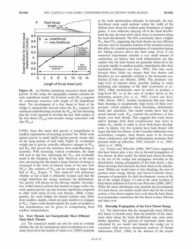
[24] The principle of work minimization predicts that thefault system will evolve to a configuration that requires theleast total work so that we can compare the energetic costsof various fault geometries to predict wedge system evolu-tion. If we neglect the acoustic energy released by slip(Wseis) and energy consumed in the formation of new faultsurface (Wprop), we can predict that the accretionary mode isfavored once the underthrust sheet is longer than 4.5 cm(Figure 10). At this length the total work of accommodatingcontraction by roof thrusting equals the work of accommo-dating contraction along a new fore thrust in front of thewedge. As the thrust sheet grows beyond 4.5 cm, the Wext
(Wint + Wgrav + Wfric) of continued underthrusting requiresgreater energy than accretion (9.04 J). However, the systempersists in the underthrusting stage. Why? The energyrequired to produce the new frontal ramp from the basaldecollement must also be taken into account. Underthrust-ing will be favored as long as the Wext is less than thatnecessary for accretion plus Wseis and Wprop for the accre-tionary model (equation (1)). The experiment of Adam et al.[2005] demonstrates that the transition from underthrustingto accretion occurs when the roof thrust is 10.5 cm long,when the model is expending 9.44 J to continue under-thrusting (Figure 10). The difference between theWext of theunderthrust model at the transition and Wext of the newaccretion model (0.4 J) reflects the energy lost during thistransition to acoustic energy and development of new faultsurface (Wseis + Wprop; Figure 10).
Figure 8. Slip along different fault locations and rampvergencemodeled. Fore thrust 2 shows the greatest amount ofslip. Positive sign is for left-lateral motion (FT), and negativesign is for right-lateral motion along the ramp (BT).
Figure 7. Weight of different work terms for under-thrusting phase (roof thrust length just prior to transition)and accretion. Fore thrust 2 is the most energeticallyefficient faulting geometry for this system setup as itdisplays the least amount of Wtot required for wedgedeformation. In all other cases, the Wint increase overrunsWfric decrease, making these faults not favorably positionedin terms of work minimization.
B12404 DEL CASTELLO AND COOKE: UNDERTHRUSTING-ACCRETION WORK BUDGET
8 of 14
B12404

[25] Although the energy required to propagate faults insand is not available due to the difficulty of these measure-ments, laboratory tests on soft cemented sedimentary rocksat low confining pressure have shownWprop around 140 J/m
2
[Labuz and Dai, 2000]. If such sandstone grew a fault aslong as the fore thrust in our accretionary models, the rockwould consume �9.7 J. Of course, we expect loose sand torequire much less energy than soft cemented sandstonebecause the unconfined compressive strength of soft,cemented sandstone is 100 times greater than that of sand.The order of magnitude of Wprop estimated by the model(<0.4 J) agrees with our expectations from available labora-tory data.[26] The values of the various work terms reported here
reflect the specific fault geometry of and material propertieswithin the numerical experiment. Although the values of thework components will vary with different fault configura-tions, the tradeoffs between the different work componentswithin the overall work budget will remain the same. Thetransition from underthrusting to accretion occurs when the
energetic benefit of slip along the new fore thrust exceedsthe energetic cost of producing this surface.
5.3. Is Work Against Gravity Not Important inSandboxes?
[27] The progressive increase of vertical overburden dueto thickening by no doubts constitutes one of the maindrivers to induce the wedge to switch from underthrusting toaccretion during cycles observed in analogue experiments[Mulugeta and Koyi, 1992; Gutscher et al., 1996; DelCastello et al., 2004]. The BEM models have relativelysmall components of work against gravity (Wgrav �; Wint
and Wfric). To some degree, this is due to the small scale ofthe sandbox, which produces small overburden pressures;larger scaled numerical models display a higher portion ofwork against gravity [Cooke and Murphy, 2004]. Adding adip to the base of the sandbox model would increase thework against gravity slightly but not to the level of the otherwork components. Our gravitational work values are in thesame order as the analytical estimates of Gutscher et al.
Figure 9. Plots of strain energy density for different fore-thrust and back-thrust location. A progressiveenlargement of wedge regions affected by high levels of strain (yellow, see scale for reference) can beobserved from Figure 9a (fore thrust 2) to Figure 9d (back thrust 1). These cross sections confirm thatfore thrust 2 accumulates the least internal strain within the wedge. The box in Figure 9a indicates thelocation of Figure 11.
B12404 DEL CASTELLO AND COOKE: UNDERTHRUSTING-ACCRETION WORK BUDGET
9 of 14
B12404
[1998]. Does this mean that gravity is insignificant insandbox experiments of accreting systems? No. While workagainst gravity is small (uplift against gravity occurs onlyon the ramp portion of each fault, Figure 4), overburdenweight due to gravity critically influences changes in Wfric
and Wint that govern the transition from underthursting toaccretion. With increasing vertical overburden, the rampwill tend to slip less, decreasing the Wfric and eventuallyresult in the clamping of the fault. However, at the sametime, decreasing the slip means a larger fraction of energy isconsumed in the form of internal strain of the host rock(Wint). The variation of Wint can be smaller or larger thanthat of Wfric (Figure 7). This trade-off will determinewhether or not a fault is efficiently located such that thewedge minimizes the energy necessary for deformation.Yet, gravity will always be the driving variable. Neverthe-less, within natural systems that operate on larger scales, thework against gravity can also become significant comparedto other work terms [Cooke and Murphy, 2004]. Conse-quently, the work budget for natural systems may differfrom sandbox models, which are quite sensitive to changesin Wfric. Future work should explore the scales of models sothat consideration can be given in extrapolating fromsandbox interpretations.
5.4. Fore Thrusts Are Energetically More EfficientThan Back Thrusts
[28] The numerical model can also be used to evaluatewhether the site for spontaneous shear localization in a newramp observed in the models of Adam et al. [2005] responds
to the work minimization principle. In principle, the newfore-thrust ramp could nucleate within the width of thedilation zone along the weakest grain boundaries or largestgrains. A new imbricate splaying off at the basal decolle-ment tip may develop where shear stress is maximum alongthe basal decollement. The BTs consistently show a higherWtot than FTs, suggesting that back thrusts are less efficientand may only be secondary features of the accretion processthat allow for a partial accommodation of contraction duringthe folding process above the fault ramp. Even if ournumerical experiments simulate a very small amount ofcontraction, we believe that work minimization can alsoexplain why the back thrusts are generally observed to dieout quite rapidly in sandbox models, immediately after theirnucleation [Mulugeta and Koyi, 1992]. This may occurbecause these faults are steeper than fore thrusts andtherefore are not optimally oriented to the horizontal con-traction [Cooke and Murphy, 2004]. This produces veryhigh level of internal strain, possibly leading to strainhardening and clamping of the fault [Lohrmann et al.,2003]. Other mechanisms must be active to produce along-lived BT, as in the case of weaker layers in thedeforming section [Liu et al., 1992; Cotton and Koyi,2000; Bonini, 2001]. Another mechanism that may favorback thrusting is exceptionally high levels of fluid over-pressure, which produces micro fracturing, deformationbands and cataclastic. Our model results show that thestored internal work, Wint, controls the preference of forethrusts over back thrusts. This suggests that weak layersand/or damage from fluid overpressures may serve toreduce Wint locally in order to favor back-thrust develop-ment. In nature, very few systems have back thrusts withlarger slip than fore thrusts. In the Cascadia subduction zoneaccretionary complex, back thrusts seem to be favoredwhere conspicuous and rapid sedimentation promotes fluidpressure build up [MacKay, 1995; Gutscher et al., 2001;Adam et al., 2004].[29] Panian and Wiltschko [2004, 2007] have suggested
that back thrusts play a key role in forward propagation offore thrusts. In their model, the initial back thrust developsat the toe of the wedge and propagates downdip to thedecollement. During propagation of the back thrust, a forethrust develops that intersects the back thrust at the decolle-ment. Within our model prior to fore thrusting, the area ofgreatest strain energy density and Navier-Coulomb stress,measures of propensity for fault development, occurs at thetip of the wedge (Figure 11) and at the same location ofback-thrust initiation of Panian and Wiltschko [2004, 2007].While the stress distribution may promote the developmentof a back thrust, our models results show that for the overallsystem, a fore thrust requires less work than the back thrustto accommodate contraction; the fore thrust is more efficientand takes over.
5.5. Downdip Propagation of the Fore-Thrust Ramp
[30] The observation that the energetically most efficientfore thrust is located away from the position of the maxi-mum shear along the basal decollement may raise somefurther questions. The position of maximum shear stresscalculated by our model just beneath the wedge toe isconsistent with previous mechanical analyses of frontalimbrication [Platt, 1988]. In the absence of the results
Figure 10. (a) Models simulating successive thrust sheetgrowth. In this setup, the topography remains constant foreach underthrust model. (b) External work (Wext) requiredfor contraction increases with length of the underthrustsheet. The development of a fore thrust in front of thewedge is energetically favored when the Wext required forcontinued underthrusting exceeds the Wext for fore thrustingplus the work required to develop the new fault surface ofthe fore thrust (Wprop) and acoustic energy associated withslip (Wseis).
B12404 DEL CASTELLO AND COOKE: UNDERTHRUSTING-ACCRETION WORK BUDGET
10 of 14
B12404
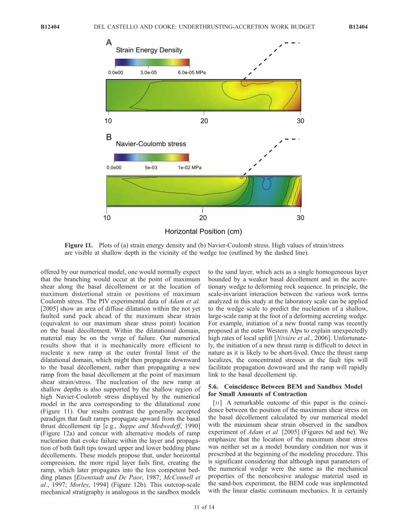
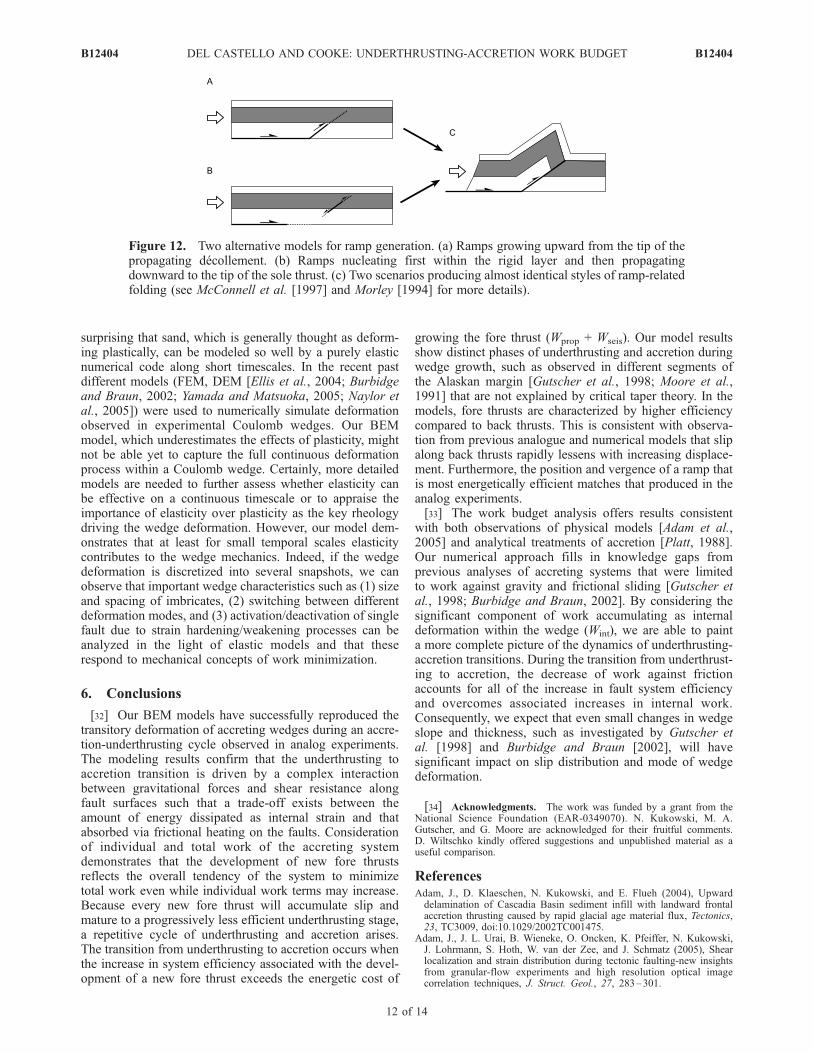
offered by our numerical model, one would normally expectthat the branching would occur at the point of maximumshear along the basal decollement or at the location ofmaximum distortional strain or positions of maximumCoulomb stress. The PIV experimental data of Adam et al.[2005] show an area of diffuse dilatation within the not yetfaulted sand pack ahead of the maximum shear strain(equivalent to our maximum shear stress point) locationon the basal decollement. Within the dilatational domain,material may be on the verge of failure. Our numericalresults show that it is mechanically more efficient tonucleate a new ramp at the outer frontal limit of thedilatational domain, which might then propagate downwardto the basal decollement, rather than propagating a newramp from the basal decollement at the point of maximumshear strain/stress. The nucleation of the new ramp atshallow depths is also supported by the shallow region ofhigh Navier-Coulomb stress displayed by the numericalmodel in the area corresponding to the dilatational zone(Figure 11). Our results contrast the generally acceptedparadigm that fault ramps propagate upward from the basalthrust decollement tip [e.g., Suppe and Medwedeff, 1990](Figure 12a) and concur with alternative models of rampnucleation that evoke failure within the layer and propaga-tion of both fault tips toward upper and lower bedding planedecollements. These models propose that, under horizontalcompression, the more rigid layer fails first, creating theramp, which later propagates into the less competent bed-ding planes [Eisenstadt and De Paor, 1987; McConnell etal., 1997; Morley, 1994] (Figure 12b). This outcrop-scalemechanical stratigraphy is analogous in the sandbox models
to the sand layer, which acts as a single homogeneous layerbounded by a weaker basal decollement and in the accre-tionary wedge to deforming rock sequence. In principle, thescale-invariant interaction between the various work termsanalyzed in this study at the laboratory scale can be appliedto the wedge scale to predict the nucleation of a shallow,large-scale ramp at the foot of a deforming accreting wedge.For example, initiation of a new frontal ramp was recentlyproposed at the outer Western Alps to explain unexpectedlyhigh rates of local uplift [Niviere et al., 2006]. Unfortunate-ly, the initiation of a new thrust ramp is difficult to detect innature as it is likely to be short-lived. Once the thrust ramplocalizes, the concentrated stresses at the fault tips willfacilitate propagation downward and the ramp will rapidlylink to the basal decollement tip.
5.6. Coincidence Between BEM and Sandbox Modelfor Small Amounts of Contraction
[31] A remarkable outcome of this paper is the coinci-dence between the position of the maximum shear stress onthe basal decollement calculated by our numerical modelwith the maximum shear strain observed in the sandboxexperiment of Adam et al. [2005] (Figures 6d and 6e). Weemphasize that the location of the maximum shear stresswas neither set as a model boundary condition nor was itprescribed at the beginning of the modeling procedure. Thisis significant considering that although input parameters ofthe numerical wedge were the same as the mechanicalproperties of the noncohesive analogue material used inthe sand-box experiment, the BEM code was implementedwith the linear elastic continuum mechanics. It is certainly
Figure 11. Plots of (a) strain energy density and (b) Navier-Coulomb stress. High values of strain/stressare visible at shallow depth in the vicinity of the wedge toe (outlined by the dashed line).
B12404 DEL CASTELLO AND COOKE: UNDERTHRUSTING-ACCRETION WORK BUDGET
11 of 14
B12404
surprising that sand, which is generally thought as deform-ing plastically, can be modeled so well by a purely elasticnumerical code along short timescales. In the recent pastdifferent models (FEM, DEM [Ellis et al., 2004; Burbidgeand Braun, 2002; Yamada and Matsuoka, 2005; Naylor etal., 2005]) were used to numerically simulate deformationobserved in experimental Coulomb wedges. Our BEMmodel, which underestimates the effects of plasticity, mightnot be able yet to capture the full continuous deformationprocess within a Coulomb wedge. Certainly, more detailedmodels are needed to further assess whether elasticity canbe effective on a continuous timescale or to appraise theimportance of elasticity over plasticity as the key rheologydriving the wedge deformation. However, our model dem-onstrates that at least for small temporal scales elasticitycontributes to the wedge mechanics. Indeed, if the wedgedeformation is discretized into several snapshots, we canobserve that important wedge characteristics such as (1) sizeand spacing of imbricates, (2) switching between differentdeformation modes, and (3) activation/deactivation of singlefault due to strain hardening/weakening processes can beanalyzed in the light of elastic models and that theserespond to mechanical concepts of work minimization.
6. Conclusions
[32] Our BEM models have successfully reproduced thetransitory deformation of accreting wedges during an accre-tion-underthrusting cycle observed in analog experiments.The modeling results confirm that the underthrusting toaccretion transition is driven by a complex interactionbetween gravitational forces and shear resistance alongfault surfaces such that a trade-off exists between theamount of energy dissipated as internal strain and thatabsorbed via frictional heating on the faults. Considerationof individual and total work of the accreting systemdemonstrates that the development of new fore thrustsreflects the overall tendency of the system to minimizetotal work even while individual work terms may increase.Because every new fore thrust will accumulate slip andmature to a progressively less efficient underthrusting stage,a repetitive cycle of underthrusting and accretion arises.The transition from underthrusting to accretion occurs whenthe increase in system efficiency associated with the devel-opment of a new fore thrust exceeds the energetic cost of
growing the fore thrust (Wprop + Wseis). Our model resultsshow distinct phases of underthrusting and accretion duringwedge growth, such as observed in different segments ofthe Alaskan margin [Gutscher et al., 1998; Moore et al.,1991] that are not explained by critical taper theory. In themodels, fore thrusts are characterized by higher efficiencycompared to back thrusts. This is consistent with observa-tion from previous analogue and numerical models that slipalong back thrusts rapidly lessens with increasing displace-ment. Furthermore, the position and vergence of a ramp thatis most energetically efficient matches that produced in theanalog experiments.[33] The work budget analysis offers results consistent
with both observations of physical models [Adam et al.,2005] and analytical treatments of accretion [Platt, 1988].Our numerical approach fills in knowledge gaps fromprevious analyses of accreting systems that were limitedto work against gravity and frictional sliding [Gutscher etal., 1998; Burbidge and Braun, 2002]. By considering thesignificant component of work accumulating as internaldeformation within the wedge (Wint), we are able to painta more complete picture of the dynamics of underthrusting-accretion transitions. During the transition from underthrust-ing to accretion, the decrease of work against frictionaccounts for all of the increase in fault system efficiencyand overcomes associated increases in internal work.Consequently, we expect that even small changes in wedgeslope and thickness, such as investigated by Gutscher etal. [1998] and Burbidge and Braun [2002], will havesignificant impact on slip distribution and mode of wedgedeformation.
[34] Acknowledgments. The work was funded by a grant from theNational Science Foundation (EAR-0349070). N. Kukowski, M. A.Gutscher, and G. Moore are acknowledged for their fruitful comments.D. Wiltschko kindly offered suggestions and unpublished material as auseful comparison.
ReferencesAdam, J., D. Klaeschen, N. Kukowski, and E. Flueh (2004), Upwarddelamination of Cascadia Basin sediment infill with landward frontalaccretion thrusting caused by rapid glacial age material flux, Tectonics,23, TC3009, doi:10.1029/2002TC001475.
Adam, J., J. L. Urai, B. Wieneke, O. Oncken, K. Pfeiffer, N. Kukowski,J. Lohrmann, S. Hoth, W. van der Zee, and J. Schmatz (2005), Shearlocalization and strain distribution during tectonic faulting-new insightsfrom granular-flow experiments and high resolution optical imagecorrelation techniques, J. Struct. Geol., 27, 283–301.
Figure 12. Two alternative models for ramp generation. (a) Ramps growing upward from the tip of thepropagating decollement. (b) Ramps nucleating first within the rigid layer and then propagatingdownward to the tip of the sole thrust. (c) Two scenarios producing almost identical styles of ramp-relatedfolding (see McConnell et al. [1997] and Morley [1994] for more details).
B12404 DEL CASTELLO AND COOKE: UNDERTHRUSTING-ACCRETION WORK BUDGET
12 of 14
B12404

Bangs, N. L., T. H. Shipley, S. P. S. Gulick, G. F. Moore, S. Kuromoto, andY. Nakamura (2004), Evolution of the Nankai Trough decollement fromthe trench into the seismogenic zone: Inferences from three-dimensionalseismic reflection imaging, Geology, 32, 273 – 276, doi:10.1130/G20211.2.
Barnhoorn, A., M. Bystricky, L. Burlini, and K. Kunze (2004), The role ofrecrystallisation on the deformation behaviour of calcite rocks: Largestrain torsion experiments on Carrara marble, J. Struct. Geol., 26,885–903.
Bird, P., and D. A. Yuen (1979), The use of minimum dissipation principlein tectonophysics, Earth Planet. Sci. Lett., 45, 214–217.
Bombolakis, E. G. (1994), Applicability of critical-wedge theories toforeland belts, Geology, 22, 535–538.
Bonini, M. (2001), Passive roof thrusting and forelandward fold propaga-tion in scaled brittle-ductile physical models of thrust wedges, J. Geo-phys. Res., 106, 2291–2311.
Buczkowski, D. L., and M. L. Cooke (2004), Formation of double-ringcircular grabens due to volumetric compaction over buried impact craters:Implications for thickness and nature of cover material in Utopia Planitia,Mars, J. Geophys. Res., 109, E02006, doi:10.1029/2003JE002144.
Burbidge, D. R., and J. Braun (2002), Numerical models of the evolution ofaccretionary wedges and fold-and-thrust belts using the distinct-elementmethod, Geophys. J. Int., 148, 542–561.
Cooke, M. L., and A. Kameda (2002), Mechanical fault interaction withinthe Los Angeles Basin: A two-dimensional analysis using mechanicalefficiency, J. Geophys. Res., 107(B7), 2146, doi:10.1029/2001JB000542.
Cooke, M. L., and S. Murphy (2004), Assessing the work budget andefficiency of fault systems using mechanical models, J. Geophys. Res.,109, B10408, doi:10.1029/2004JB002968.
Cooke, M. L., and D. D. Pollard (1997), Bedding-plane slip in initial stagesof fault-related folding, J. Struct. Geol., 19, 567–581.
Cooke, M. L., and C. A. Underwood (2001), Fracture termination and step-over at bedding interfaces due to frictional slip and interface opening,J. Struct. Geol., 23, 223–238.
Cooke, M. L., D. Mollema, D. D. Pollard, and A. Aydin (2000), Interlayerslip and joint localization in East Kaibab Monocline, Utah: Fieldevidence and results from numerical modeling, in Forced Folds andFractures, edited by J. W. Cosgrove and M. S. Ameen, Geol. Soc. Spec.Publ., 169, 23–49.
Cotton, J. T., and E. Koyi (2000), Modeling of thrust fronts above ductileand frictional detachments: Application to structures in the Salt Rangeand Potwar Plateau, Pakistan, Geol. Soc. Am. Bull., 112, 351–363.
Cox, S. J. D., and C. H. Scholz (1988), Rupture initiation in shear fractureof rocks: An experimental study, J. Geophys. Res., 93, 3307–3320.
Crouch, S. L. and A. M. Starfield (1990), Boundary Element Methods inSolid Mechanics, Unwin Hyman, Boston, Mass.
Dahlen, F. A. (1990), Critical taper model of fold-and-thrust belts andaccretionary wedges, Annu. Rev. Earth Planet. Sci. Lett., 18, 55–99.
Dahlen, F. A., J. Suppe, and D. Davis (1984), Mechanics of fold-and-thrustbelts and accretionary wedges: Cohesive Coulomb theory, J. Geophys.Res., 89, 87–101.
Del Castello, M., G. A. Pini, and K. R. McClay (2004), Effect of unbalancedtopography and overloading on Coulomb wedge kinematics: Insightsfrom sandbox modeling, J. Geophys. Res., 109, B05405, doi:10.1029/2003JB002709.
Eisenstadt, G., and D. G. De Paor (1987), Alternative model of thrust-faultpropagation, Geology, 15, 630–633.
Ellis, S., G. Schreurs, and M. Panien (2004), Comparisons betweenanalogue and numerical models of thrust wedge development, J. Struct.Geol., 26, 1659–1675.
Ford, M. (2004), Depositional wedge tops: Interaction between low basalfriction external orogenic wedges and flexural foreland basins, BasinRes., 16, 361–375.
Gutscher, M. A., N. Kukowski, J. Malavieille, and S. Lallemand (1996),Cyclic behavior of thrust wedges: Insights from high basal frictionsandbox experiments, Geology, 24, 135–138.
Gutscher, M. A., N. Kukowski, J. Malavieille, and S. Lallemand (1998),Episodic imbricate thrusting and underthrusting: Analog experiments andmechanical analysis applied to the Alaskan Accretionary Wedge, J. Geo-phys. Res., 103, 10,161–10,176.
Gutscher, M. A., D. Klaeschen, E. Flueh, and J. Malavieille (2001), Non-Coulomb wedges, wrong-way thrusting, and the natural hazards inCascadia, Geology, 29, 379–382.
Jaeger, J. C. and N. G. Cook (1969), Fundamentals of Rock Mechanics, 513pp., Methuen, London.
Konstantinovskaia, E., and J. Malavieille (2005), Erosion and exhumationin accretionary orogens: Experimental and geological approaches,Geochem. Geophys. Geosyst., 6, Q02006, doi:10.1029/2004GC000794.
Kukowski, N., S. E. Lallemand, J. Malavieille, M. A. Gutscher, and T. J.Reston (2002), Mechanical decoupling and basal duplex formation
observed in sandbox experiments with application to the WesternMediterranean Ridge accretionary complex, Mar. Geol., 186, 29–42.
Labuz, J. F., and S. T. Dai (2000), Residual strength and fracture energyfrom plane-strain testing, J. Geotech. Geoenviron. Eng., 126, 882–889.
Lallemand, S. E., P. Schnurle, and J. Malavieille (1994), Coulomb theoryapplied to accretionary and non-accretionary wedges: Possible causes fortectonic erosion and/or frontal accretion, J. Geophys. Res., 99, 12,033–12,055.
Lambe, T. W. and R. V. Whitman (1969), Soil Mechanics, 553 pp., JohnWiley, New York.
Liu, H., K. R. McClay, and D. Powell (1992), Physical models of thrustwedges, in Thrust Tectonics, edited by K. R. McClay, pp. 71 –81,Chapman and Hall, New York.
Lohrmann, J., N. Kukowski, J. Adam, and O. Oncken (2003), The impactof analogue material properties on the geometry, kinematics, anddynamics of convergent sand wedges, J. Struct. Geol., 25, 1691–1711.
MacKay, M. E. (1995), Structural variation and landward vergence at thetoe of the Oregon accretionary prism, Tectonics, 14, 1309–1320.
Marone, C. (1998), Laboratory-derived friction laws and their application toseismic faulting, Annu. Rev. Earth Planet. Sci. Lett., 26, 643–696.
Masek, J. G., and C. C. Duncan (1998), Minimum-work mountain building,J. Geophys. Res., 103, 907–917.
McCaffrey, R., M. D. Long, C. Goldfinger, P. C. Zwick, J. L. Nabelek, C. K.Johnson, and C. Smith (2000), Rotation and plate locking at the southernCascadia subduction zone, Geophys. Res. Lett., 27, 3117–3120.
McClay, K. R. and P. S. Whitehouse (2004), Analog modeling of doublyvergent thrust wedges, in Thrust Tectonics and Hydrocarbon Systems,edited by K. R. McClay, AAPG Mem., 82, 187–209.
McConnell, D. A., S. A. Kattenhorn, and L. M. Benner (1997), Distributionof fault slip in outcrop-scale fault-related folds, Appalachian Mountains,J. Struct. Geol., 19, 257–267.
Melosh, H. J., and C. A. Williams Jr. (1989), Mechanics of grabenformation in crustal rocks: A finite element analysis, J. Geophys. Res.,94, 13,961–13,973.
Mitra, G., and S. E. Boyer (1986), Energy balance and deformationmechanisms of duplexes, J. Struct. Geol., 8, 291–304.
Moore, J. C., et al. (1991), Edge deep seismic-reflection transect of theeastern Aleutian arc-trench layered lower crust reveals underplating andcontinental growth, Geology, 19, 420–424.
Morley, C. K. (1994), Fold-generated imbricates: Examples from theCaledonides of southern Norway, J. Struct. Geol., 16, 619–631.
Mulugeta, G., and H. Koyi (1992), Episodic accretion and strain partition-ing in a model sand wedge, Tectonophysics, 202, 319–333.
Naylor, M., H. D. Sinclair, S. Willett, and P. A. Cowie (2005), A discreteelement model for orogenesis and accretionary wedge growth, J. Geo-phys. Res., 110, B12403, doi:10.1029/2003JB002940.
Niviere, B., M. Giamboni, I. Christophe, and T. Winter (2006), Kinematicevolution of a tectonic wedge above a flat-lying decollement: The Alpineforeland at the interface between the Jura Mountains (Northern Alps) andthe Upper Rhine Graben, Geology, 34, 469–472.
Okubo, C. H., and R. A. Schultz (2005), Evolution of damage zonegeometry and intensity in porous sandstone: Insight gained from strainenergy density, J. Geol. Soc. London, 162, 939–949.
Panian, J., and D. Wiltschko (2004), Ramp initiation in a thrust wedge,Nature, 427, 624–627.
Panian, J., and D. Wiltschko (2007), Ramp initiation and spacing in ahomogeneous thrust wedge, J. Geophys. Res., 112, B05417,doi:10.1029/2004JB003596.
Panien, M., G. Schreurs, and A. Pfiffner (2006), Mechanical behaviour ofgranular materials used in analogue modelling: Insights from graincharacterisation, ring-shear tests and analogue experiments, J. Struct.Geol., 28, 1710–1724.
Platt, J. P. (1988), The mechanics of frontal imbrication: A first orderanalysis, Geol. Rundsch., 77, 577–589.
Rabinowicz, E. (1958), The intrinsic variables affecting the stick-slipprocess, Proc. Phys. Soc., 71, 668–675.
Roering, J. J., M. L. Cooke, and D. D. Pollard (1997), Why blind thrustfaults do not propagate to the Earth’s surface: Numerical modeling ofcoseismic deformation associated with thrust-related anticlines, J. Geo-phys. Res., 102, 11,901–11,912.
Saffer, D. M., and B. A. Bekins (2006), An evaluation of factorsinfluencing pore pressure in accretionary complexes: Implications fortaper angle and wedge mechanics, J. Geophys. Res., 111, B04101,doi:10.1029/2005JB003990.
Scholz, C. H. (2002), The Mechanics of Earthquakes and Faulting, 472 pp.,Cambridge Univ. Press, New York.
Sleep, N. H., S. Stein, R. J. Geller, and R. G. Gordon (1979), Comment on‘‘The use of the minimum-dissipation principle in tectonophysics’’ byP. Bird and D. A. Yuen, Earth Planet. Sci. Lett., 45, 218–220.
B12404 DEL CASTELLO AND COOKE: UNDERTHRUSTING-ACCRETION WORK BUDGET
13 of 14
B12404

Song, T. A., and M. Simons (2003), Large trench-parallel gravity variationspredict seismogenic behavior in subduction zones, Science, 301, 630–633.
Storti, F., and K. McClay (1995), Influence of syntectonic sedimentation onthrust wedges in analog models, Geology, 23, 999–1002.
Suppe, J., and D. A. Medwedeff (1990), Geometry and kinematics of fault-propagation folding, Eclogae Geol. Helv., 83, 409–454.
Timoshenko, S. P. and J. N. Goodier (1934), Theory of Elasticity,McGraw-Hill, New York.
Vannucchi, P., C. R. Ranero, S. Galeotti, S. M. Straub, D. W. Scholl, andK. McDougall-Reid (2003), Fast rates of subduction erosion along theCosta Rica Pacific margin: Implications for nonsteady rates of crustalrecycling at subduction zones, J. Geophys. Res., 108(B11), 2511,doi:10.1029/2002JB002207.
Wang, K., and Y. Hu (2006), Accretionary prisms in subduction earthquakecycles: The theory of dynamic Coulomb wedge, J. Geophys. Res., 111,B06410, doi:10.1029/2005JB004094.
Wells, R. E., R. J. Blakely, Y. Sugiyama, D. W. Scholl, and P. A. Dinterman(2003), Basin-centered asperities in great subduction zone earthquakes:
A link between slip, subsidence, and subduction erosion?, J. Geophys.Res., 108(B10), 2507, doi:10.1029/2002JB002072.
Wong, T. F. (1982), Shear fracture energy of Westerly granite from post-failure behavior, J. Geophys. Res., 87, 990–1000.
Wong, T. F. (1986), On the normal stress dependence of the shear fractureenergy, in Earthquake Source Mechanics, Geophys. Monogr. Ser.,vol. 37, edited by S. Das, J. Boatwright, and C. H. Scholz, pp. 1–12,AGU, Washington, D. C.
Yamada, Y. and T. Matsuoka (2005), Digital sandbox modeling usingdistinct element method: Applications to fault tectonics, in Faults, fluidflow, and Petroleum Traps, edited by R. Sorkhabi and Y. Tsuji, AAPGMem., 85, 107–123.
�����������������������M. L. Cooke and M. Del Castello, Geosciences Department, University
of Massachusetts, 611 North Pleasant Street, Amherst, MA 01003, USA.([email protected])
B12404 DEL CASTELLO AND COOKE: UNDERTHRUSTING-ACCRETION WORK BUDGET
14 of 14
B12404