understanding your 30s-1 by bill carns, k0cxx a … bill carns, k0cxx a preface for the uninitiated,...
TRANSCRIPT

Understanding Your 30S-1 ©
By Bill Carns, K0CXX
A Preface For the uninitiated, tuning a higher power amplifier can be a bit intimidating. On one hand, they do deserve a bit more “respect”, but on the other hand, a 30S-1 is no different than a 30L-1 or your driver PA for that matter. The noises just get louder, and the repair bill higher, when those “events” happen. The following is meant to be a primer for those so intimidated, or new to the game. Tuning is actually pretty straight forward and, if you follow the basic steps, the results gratifying and easy to achieve. Some of you may know most of this. However, reading through this you may find a new perspective or a tidbit or two that you did not know – or that will help your perspective on what is happening inside and outside the amp during its operation. Enjoy.
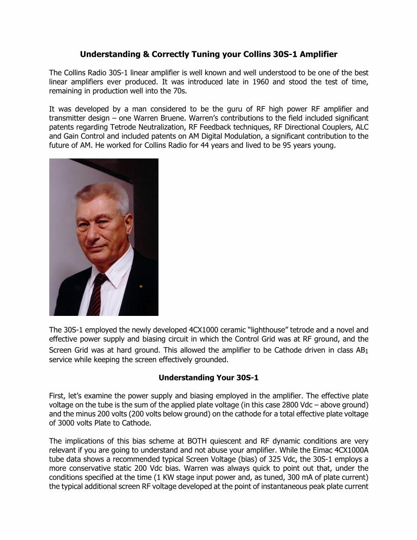
Understanding & Correctly Tuning your Collins 30S-1 Amplifier The Collins Radio 30S-1 linear amplifier is well known and well understood to be one of the best linear amplifiers ever produced. It was introduced late in 1960 and stood the test of time, remaining in production well into the 70s. It was developed by a man considered to be the guru of RF high power RF amplifier and transmitter design – one Warren Bruene. Warren’s contributions to the field included significant patents regarding Tetrode Neutralization, RF Feedback techniques, RF Directional Couplers, ALC and Gain Control and included patents on AM Digital Modulation, a significant contribution to the future of AM. He worked for Collins Radio for 44 years and lived to be 95 years young.
The 30S-1 employed the newly developed 4CX1000 ceramic “lighthouse” tetrode and a novel and effective power supply and biasing circuit in which the Control Grid was at RF ground, and the
Screen Grid was at hard ground. This allowed the amplifier to be Cathode driven in class AB1
service while keeping the screen effectively grounded.
Understanding Your 30S-1 First, let’s examine the power supply and biasing employed in the amplifier. The effective plate voltage on the tube is the sum of the applied plate voltage (in this case 2800 Vdc – above ground) and the minus 200 volts (200 volts below ground) on the cathode for a total effective plate voltage of 3000 volts Plate to Cathode. The implications of this bias scheme at BOTH quiescent and RF dynamic conditions are very relevant if you are going to understand and not abuse your amplifier. While the Eimac 4CX1000A tube data shows a recommended typical Screen Voltage (bias) of 325 Vdc, the 30S-1 employs a more conservative static 200 Vdc bias. Warren was always quick to point out that, under the conditions specified at the time (1 KW stage input power and, as tuned, 300 mA of plate current) the typical additional screen RF voltage developed at the point of instantaneous peak plate current
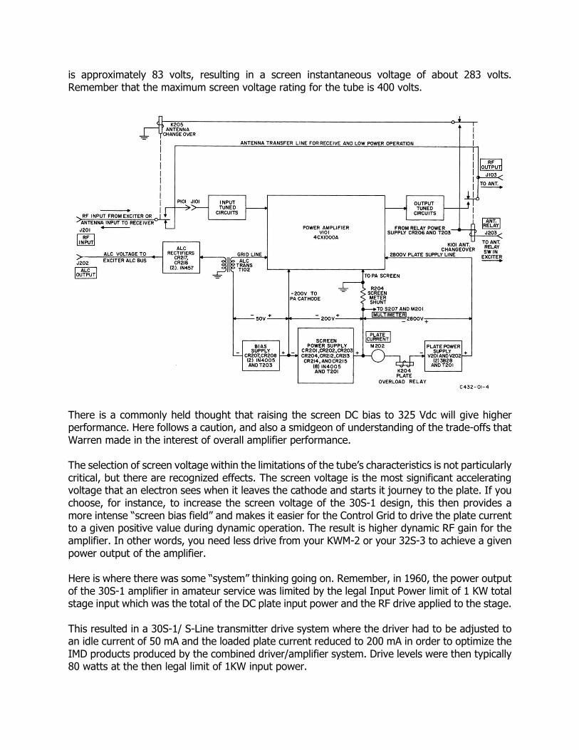
is approximately 83 volts, resulting in a screen instantaneous voltage of about 283 volts. Remember that the maximum screen voltage rating for the tube is 400 volts.
There is a commonly held thought that raising the screen DC bias to 325 Vdc will give higher performance. Here follows a caution, and also a smidgeon of understanding of the trade-offs that Warren made in the interest of overall amplifier performance. The selection of screen voltage within the limitations of the tube’s characteristics is not particularly critical, but there are recognized effects. The screen voltage is the most significant accelerating voltage that an electron sees when it leaves the cathode and starts it journey to the plate. If you choose, for instance, to increase the screen voltage of the 30S-1 design, this then provides a more intense “screen bias field” and makes it easier for the Control Grid to drive the plate current to a given positive value during dynamic operation. The result is higher dynamic RF gain for the amplifier. In other words, you need less drive from your KWM-2 or your 32S-3 to achieve a given power output of the amplifier. Here is where there was some “system” thinking going on. Remember, in 1960, the power output of the 30S-1 amplifier in amateur service was limited by the legal Input Power limit of 1 KW total stage input which was the total of the DC plate input power and the RF drive applied to the stage. This resulted in a 30S-1/ S-Line transmitter drive system where the driver had to be adjusted to an idle current of 50 mA and the loaded plate current reduced to 200 mA in order to optimize the IMD products produced by the combined driver/amplifier system. Drive levels were then typically 80 watts at the then legal limit of 1KW input power.
If Warren had elected to use a higher Screen Bias Voltage, the basic RF gain of the amplifier would have increased, the required S-Line drive power (already low) would have gone down and it would have resulted in a “system” where it would have been much easier for an operator to over-drive the amplifier and to risk getting up against the Screen Voltage absolute maximum rating. Let’s say you raise the Screen Grid bias to 300 Vdc. Perhaps you are doing that to get more gain but for sure you are doing that to get more power out. So, the instantaneous Screen Grid voltage is now north of 290 (RF + DC) volts peak (you pick your poison) and the tube is getting right up there against the screen limit. In other words, it would have been a lot easier for the average amateur radio operator to produce a less than stellar signal and/or damage the tube. Notice here that we are talking about total system considerations. This is always a good perspective to think about when you are choosing to monkey with one parameter of a known quality “system” in order to get a “better” result. Well, you say, we are going to substitute in a 4CX1500B. Hmmmm This tube indeed is a bit more rugged. The Control Grid rating is now 1 Watt max dissipation, so you can now get away with running a little Control Grid current without disaster, but notice something else. The Screen Grid ratings are the same (400 Volts Max and 12 Watts dissipation). Now look at the data sheet and the typical class AB1 operating recommendations for both tubes. Some years had gone by since Eimac designed the 4CX1000A, and they had gotten more
experience with this tube family. The Screen Grid Typical Operating condition for Class AB1
operation now shows not 325 V on the screen, but 225 V, and the “Useful” output power has actually been reduced from the 1600 plus Watts shown for the 4CX1000A to 1100 watts for the 4CX1500B. OK, let’s park that thought for a while and look at another aspect of Warren’s system design. He was also VERY quick to point out that the 30S-1 was designed (as a system) to provide very low fan noise. He talked about the fact that since the legal limit was 1 KW PA stage DC input power, Collins had reduced the airflow from the Eimac spec’d (sea level) airflow of 25 CFM for max dissipation rating (1 KW to start with) to a lower flow in order to use both a smaller fan, and to produce less air impact noise in the ductwork. (For reference, at 25 CFM, the pressure drop across the 4CX1000A is just 0.2 inches of water column) Note: Therefore, your 30S-1 4CX1000A is NOT rated at 1 KW dissipation. Unfortunately, until we get some good actual airflow data, we do not know what the rating is. Operating the amplifier at greater than the manual recommended plate currents (higher Pout) therefore puts you in no man’s land. OK, but we can substitute a 4CX1500B. You get better Control Grid dissipation and higher plate dissipation. But, wait! Looking at the data sheet for the 1500B, we see that the specified airflow for its rating of 1500 watts is not 25 CFM (Sea Level), but rather 34 CFM with a pressure drop of 0.6 inches of water column. Looking carefully at the tube, we also see that the fin density of the 4CX1500B is denser than the 4CX1000 - and thus the airflow as used in the 30S-1 will be even lower than it was with the original tube.
More no man’s land - and it gets worse. When you sub a 4CX1500B for the designed 4CX1000A, as we said, the airflow though the tube is lower. How much, we do not know. Sitting on top of the tube, and serving as a last ditch protector of your tube and amplifier, is a bimetallic strip thermal interlock sensor. If the air temperature of the cooling air reached the point where the bimetallic strip opens the interlock, the amp drops off line (HV kicks out) and gives you a moment to think about things. If you look carefully at the circuitry surrounding this interlock, you will see that the trip point is adjustable. This adjustment is accomplished by running a AC bias current through the strip to heat it up (or bias it up thermally) so that it is closer to tripping. Interesting is the fact that, if you consider the static (no drive applied - so no thermal rise of the tube air above the idle temperature) bias temperature of this thermal interlock, this temperature is a function of airflow over the sensor. Reduce the airflow (by substituting a 4CX1500B into the equation) and the bias temperature of the thermal interlock, K102, will rise, making it more sensitive and causing it to trip at a lower air temperature. Ha…more systems considerations. The practical result of all of this involves both tube configurations. If you are tempted to just run a little (maybe a lot) higher Pout with the 4CX1000A and the amp otherwise stock, but push it above the 1 KW input power operating limit, that sensor will get you at some point. If you run a 4CX1500B and maybe the higher screen voltage with a boost mod, then the airflow will be reduced and the sensor will get you, unless you adjust it of course. What we see in many actual cases is that the sensor is moved, or removed, from the airflow and tube protection is lost. Now, fan failure = Tube destruction. Or, some folks figure out the adjustment, and “tweak” it using Kentucky windage. This is not a good plan. This lands you deep in no man’s land again. In the manual, the adjustment of K102 is listed as a factory adjustment and “Do Not Tamper”. I have seen the factory adjustment spec, and it is not for the faint of heart. You need to drive the amp above limits VERY CAREFULLY. Then quickly – after it stabilizes – adjust R106 that controls the AC bias current through T103 and K102. Someone who is not experienced in this adjustment may well damage the tube in the process. What is the take away from all of this? Each of you must reach your own conclusions. We all know that the 30S-1 (as unmodified and with a 4CX1000A installed) is capable of running better than 1000 Watts Pout. Many do it regularly with no apparent damage done. Stay within tube limits, suffer the occasional thermal sensor trip and all is well in amplifier land. I happen to use a 4CX1500B in my amplifier and like the fact that it is a bit more robust on average. I do not drive it hard. The fact is that the small difference between 1000 Watts output and 1500 Watts output is a mere 1.76 dB increase in power into your antenna, which equates to less than a half S-Unit at the other end of the path.. Now, do I do the full legal power enchilada when running my 204H (which is rated conservatively at 2.5 KW) – of course I do. I like full power as much as the next guy when it is useful. In many case it is not necessary at all.
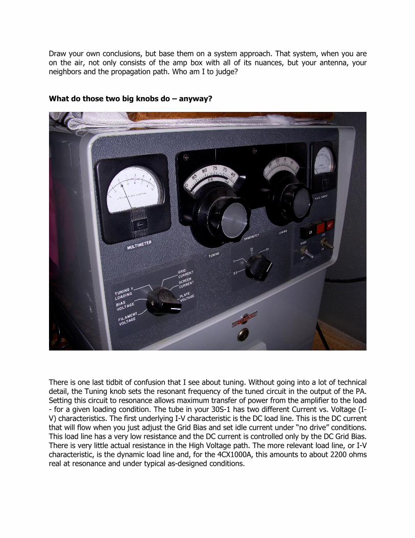
Draw your own conclusions, but base them on a system approach. That system, when you are on the air, not only consists of the amp box with all of its nuances, but your antenna, your neighbors and the propagation path. Who am I to judge? What do those two big knobs do – anyway?
There is one last tidbit of confusion that I see about tuning. Without going into a lot of technical detail, the Tuning knob sets the resonant frequency of the tuned circuit in the output of the PA. Setting this circuit to resonance allows maximum transfer of power from the amplifier to the load - for a given loading condition. The tube in your 30S-1 has two different Current vs. Voltage (I-V) characteristics. The first underlying I-V characteristic is the DC load line. This is the DC current that will flow when you just adjust the Grid Bias and set idle current under “no drive” conditions. This load line has a very low resistance and the DC current is controlled only by the DC Grid Bias. There is very little actual resistance in the High Voltage path. The more relevant load line, or I-V characteristic, is the dynamic load line and, for the 4CX1000A, this amounts to about 2200 ohms real at resonance and under typical as-designed conditions.
The output matching network (typically a PI configuration) converts the impedance of the antenna to the proper load impedance for the tube. To do this, the network must be tuned to resonance, meaning the load presented to the tube is purely resistive. The job of the Loading control (the loading capacitor) is to transform the - hopefully close to 50 ohm real - antenna impedance into something that looks close to 2200 ohms at the tube plate. The combination of the correctly set Loading control, inductor and the Tuning control does this. And, as you know from tuning, this is an interactive process. This is because resonance of the matching network is affected by both the Load and Tune controls. (As an example, let’s assume we have a properly adjusted PI network that is resonant and converts 50 to 2200. If the Load control is “increased” (its capacitance is reduced) and the network re-resonated with the Tune control, the resistive load presented to the tube decreases. So, the tube “loading” is indeed increased. Note that in this example, the inductor remains the same value, so the Q of the circuit is different from the original. By varying the inductor value, the Q could be made to be the same.) When you are increasing loading (note this because some are confused here), you are actually reducing loading shunt capacitance, and you are shifting the dynamic load line impedance up on the Y-axis (current). This equates to a lower impedance dynamic load line. Remember: Lower capacitance equals increased loading. More system perspective Also note that the amplifier ALC circuit detects the RF grid drive level and makes proportional ALC available to the driving transmitter such that there is about 3 db of override authority. This circuit has been factory set – if it has not been monkeyed with – using the (as designed) legal limit derived power output and required drive. If you elect to tune the amplifier above this level, regardless of what other changes have been made, the ALC compression will be more severe and onset too early. This ALC alignment should be changed if you elect to go to higher power output. It should also be noted that changes in screen bias and the subsequent change in amplifier gain will also change the relationship between desired output level and ALC authority. I think you are starting to get the point about making changes without understanding, and taking into account the balance of the “system”.
Some other Considerations Control Yourself While this may seem a bit unrelated to tuning, the following comments are very relevant and an area where we commonly see confusion and mistakes being made. When you define “Tuning” as the process where you make sure that the amplifier is operating properly, putting out its cleanest signal and not hurting itself, then the following is VERY relevant.
Analog meter movements are essentially an averaging measurement system. They react to waveforms in a way that tends to make them an averaging device. They are made of mechanical parts that have mass, and so they do not give you a real time version of a time varying current or voltage, but rather a delayed (and “squashed”) version. This phenomena is related to the “meter ballistics”. In other words, whether you are looking at plate current on your driving rig, on the amp, or at the resulting power output of either, after you tune up in Lock Key and note the resulting drive and amplifier output power, do not expect to ever see those readings again in normal operation. To the unknowledgeable, or un-indoctrinated, this can result in creeping mic gain – or carrier level – and then over-driving the amplifier with the resulting compromise (sometimes quite severe) of IMD performance and splatter. If you feel like you are not getting what you expect, go back to Lock Key quickly, or get yourself a peak-reading wattmeter. Saying “Ahhhhhhhhhhhh” into the microphone can often get you to the correct (or close) reading but it just does not sound that great on the air. About tuning in general Rule number one when tuning an amplifier – any amplifier: Start at reduced drive and STAY DIPPED, which means the network is adjusted to resonance and the plate current is at minimum. Sneaking up on the tuning is good. It adds some time to the tuning – maybe, but it helps protect the amplifier and the tube. Always read the manual and follow the directions contained. A 30L-1 for instance has some duty cycle tuning considerations that must be considered when tuning, or you will overheat the tubes. Then, RESONANCE is next to Godliness. Consider: The 30S-1 as shipped used the 4CX1000A rated at 1 KW dissipation under optimum cooling conditions. At rated output, and about 300 mA amplifier plate current in Lock Key mode (constant Carrier), the output power will be about 850-900 watts. Under these conditions, dissipation in the tube is a mere 150 watts. Now consider letting the amplifier get out of resonance (undipped). We all know that the plate current will rise and the power output will fall. Suddenly, power input can be 1200 watts and Pout falls to say 500 watts and the dissipation soars (just as quick as you can turn that knob) to 700 watts. Stay out of dip too long, get the drive a little too high, and that dissipation number can get right up to the limit. That is why you stay dipped. And, by the way, all of the above assumes you have a 50 ohm antenna being presented to the amp. A quick look at a VSWR table will tell you that, if you are say at 2:1 VSWR (not all that bad), add another about 80 watts into the dissipation result. Rule number two for a Tetrode amplifier: Tune the amplifier to a tad over-loaded condition. Then, operate at a slightly lower level. This will improve IMD and reduce grid current. That means operating it at a point below where you loaded it to. The 30S-1 manual (read that Warren Bruene) recommends loading to 350 MA in Lock Key and then backing off on the drive in Lock Key until
300 MA plate current is read. Then you leave the driver carrier gain adjust set right there for SSB operation.
The actual tuning Now that you have some better understanding of what is going on, let’s talk turkey. Tuning is not an overly complicated or difficult process. It should start with reading the manual. I can’t emphasize enough how important this is and basically just follow the instructions. But, tuning is summarized here for completeness of this article. Start by preparing your driver transmitter. Because less than full output power is required to drive the 30S-1 (and the 30L-1), the driver should be set up for lower power output. This involves more than just turning down the mic gain and Pout. Set the idle current of the 32S-X transmitter, or the KWM-1 or 2, to 50 mA and tune the driver into a dummy load or directly into a good antenna, but load it only to 200 mA in place of the normal 230 mA. The driver is now ready to use with the 30S-1. Make sure you are using ALC if at all possible as this improves the IMD and protects you from accidental overdrive (and Grid Current). Bring the amplifier on line and let it warm up until the HV lamp and HV will come on.
1. Start with the mic gain turned all the way down 2. Select the band of interest on the 30S-1 3. Preset the tuning control to the center of the band segment indicated on the lower (difficult
to see) part of the dial disk below the logging scale 4. Set the 30S-1 load control almost all the way to the left (CCW – low numbers) 5. Place the multimeter switch in the Control Grid Position (Grid Current) & monitor closely
during tuning 6. Go back and forth between Grid Current and Screen Current.
a. Allow no Grid Current – Ever b. Try to keep Screen Current under 10 mA – I usually see almost none.
7. Select Lock Key with the driving rig (You can start with the Tune position, but this is not necessary if the driver is already tuned and you are careful).
8. Increase the mic gain (carrier control) until you get some indication of 30S-1 plate current rise.
9. Immediately dip the 30S-1 Plate Tuning. 10. Increase the amp loading. The plate current should rise and then quickly redip
the plate current. You should be seeing some power output. 11. Repeat steps 8 thru 10 until you reach 350-400 mA of plate current dipped on the 30S-1. 12. Reduce the drive to get 300-350 mA of plate current. Leave the Loading & Tuning where
they were. 13. Give the amp a break and let it cool taking the driver out of Lock Key. Leave the Mic Gain
set where it is. Select the correct sideband on the driver. 14. You should have seen over 6 dB of ALC indication on the driving rig meter with it set to ALC
position. Now, in normal SSB operation, you should see about 6 dB (32S series) or S6
reading on the KWM-1/2 series on voice peaks. You should increase the mic gain slightly (only if you need to) to get these ALC readings.
Note that if you are driving the amplifier to higher than “book” power output, the ALC will be out of calibration. Just leave the mic gain/carrier control alone. You are now ready to operate. See the above comments about average readings and meter ballistics. Enjoy! de Bill, K0CXX
© Copyright 2015, All Rights Reserved