understanding the …support.softrol.com/custsites/softrol/conveyor manual.pdfunderstanding the...
TRANSCRIPT

Understanding theautoPulseautoPulseautoPulseautoPulseautoPulseautoPulseautoPulseautoPulse
ConveyorSystem
1100 Northpoint Parkway
Acworth, GA 30102
770.974.2700
www.softrol.com

AUTOPULSE
AUTOAUTOAUTOAUTOPPPPULSEULSEULSEULSE SSSSOFOFOFOFTTTTROLROLROLROL
This Page has been intentionally left blank.
AUTOPULSE
3: 1 AutoPulse SOFTROL
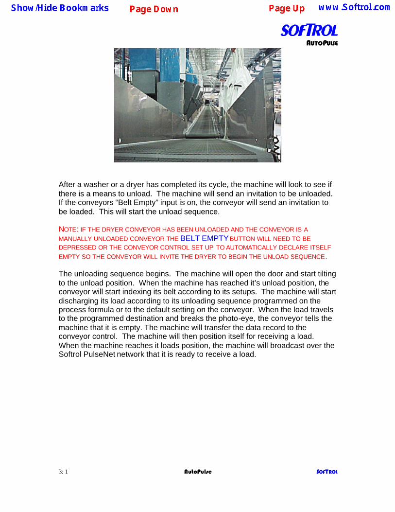
After a washer or a dryer has completed its cycle, the machine will look to see if there is a means to unload. The machine will send an invitation to be unloaded. If the conveyors “Belt Empty” input is on, the conveyor will send an invitation to be loaded. This will start the unload sequence. NOTE: IF THE DRYER CONVEYOR HAS BEEN UNLOADED AND THE CONVEYOR IS A MANUALLY UNLOADED CONVEYOR THE BELT EMPTY BUTTON WILL NEED TO BE DEPRESSED OR THE CONVEYOR CONTROL SET UP TO AUTOMATICALLY DECLARE ITSELF EMPTY SO THE CONVEYOR WILL INVITE THE DRYER TO BEGIN THE UNLOAD SEQUENCE. The unloading sequence begins. The machine will open the door and start tilting to the unload position. When the machine has reached it’s unload position, the conveyor will start indexing its belt according to its setups. The machine will start discharging its load according to its unloading sequence programmed on the process formula or to the default setting on the conveyor. When the load travels to the programmed destination and breaks the photo-eye, the conveyor tells the machine that it is empty. The machine will transfer the data record to the conveyor control. The machine will then position itself for receiving a load. When the machine reaches it loads position, the machine will broadcast over the Softrol PulseNet network that it is ready to receive a load.
AUTOPULSE
3: 2 AutoPulse SOFTROL
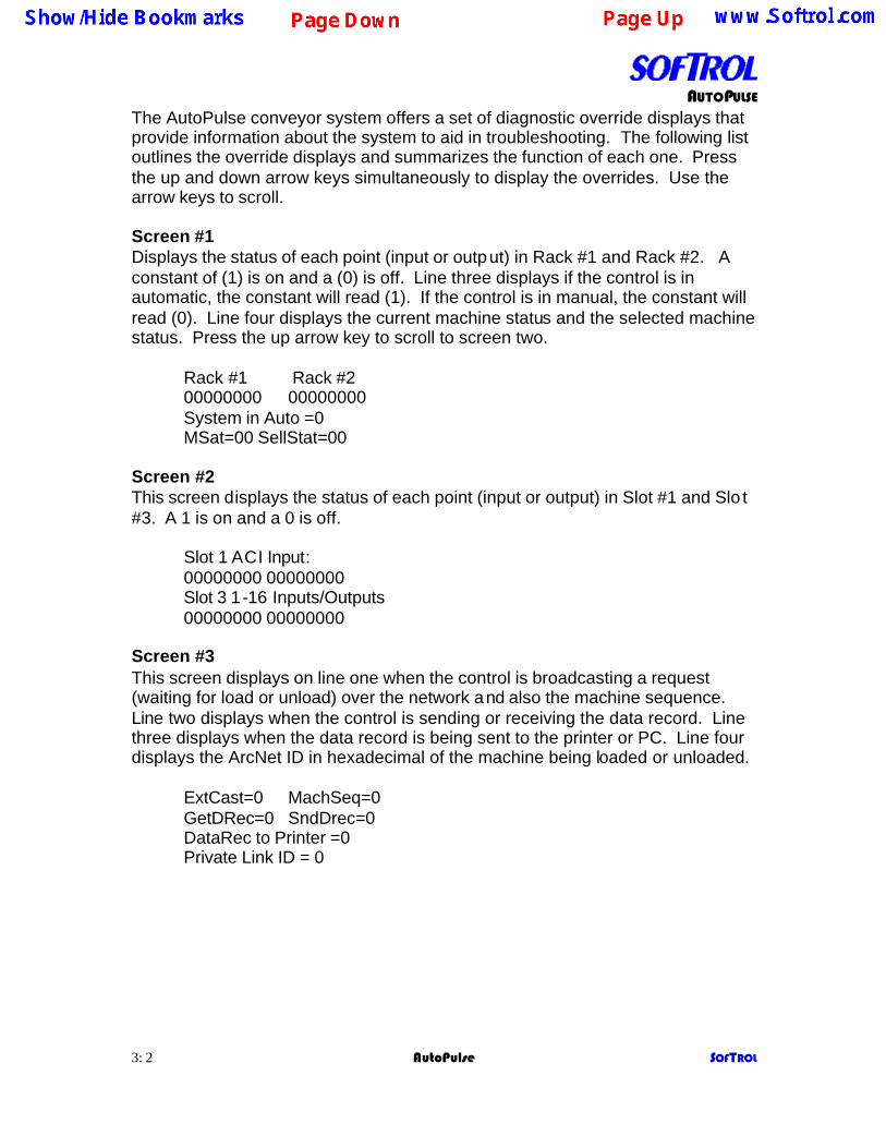
The AutoPulse conveyor system offers a set of diagnostic override displays that provide information about the system to aid in troubleshooting. The following list outlines the override displays and summarizes the function of each one. Press the up and down arrow keys simultaneously to display the overrides. Use the arrow keys to scroll. Screen #1 Displays the status of each point (input or output) in Rack #1 and Rack #2. A constant of (1) is on and a (0) is off. Line three displays if the control is in automatic, the constant will read (1). If the control is in manual, the constant will read (0). Line four displays the current machine status and the selected machine status. Press the up arrow key to scroll to screen two. Rack #1 Rack #2 00000000 00000000
System in Auto =0 MSat=00 SellStat=00
Screen #2 This screen displays the status of each point (input or output) in Slot #1 and Slo t #3. A 1 is on and a 0 is off.
Slot 1 ACI Input: 00000000 00000000 Slot 3 1-16 Inputs/Outputs 00000000 00000000
Screen #3 This screen displays on line one when the control is broadcasting a request (waiting for load or unload) over the network and also the machine sequence. Line two displays when the control is sending or receiving the data record. Line three displays when the data record is being sent to the printer or PC. Line four displays the ArcNet ID in hexadecimal of the machine being loaded or unloaded.
ExtCast=0 MachSeq=0 GetDRec=0 SndDrec=0 DataRec to Printer =0 Private Link ID = 0

AUTOPULSE
3: 3 AutoPulse SOFTROL
Screen #4 This screen displays on line one the programmed unload sequence. Line two displays the item code and the customer code. Line three displays the destination and lot number. Line four displays the dryer classification and the dry formula number.
DATAREC ULPrm = 0 I = 0 C= 0 D = 0 L = 0 DClass=00 Dform=00
Screen #5 This screen displays on line one the connecting belt ID’s. Line two displays the unload parameters positive and negative ends. Line three displays the post process to receive low limits and high limits.
CB ID’s 0 0 0 0 UnLs PP 00 NP 00 PP LL 0 HL 00000
(blank line) Screen #6 This screen displays the status of a semi-automatic interface with each point (input or output) for an Auxiliary Rack and Slot #7. A 1 is on and a 0 is off.
AuxRACK1 In / Out: Inp=0000 Out=0000 Slot 7 1-16 Inputs/Outputs 00000000 00000000
Screen #7 This screen is for Softrol troubleshooting.
Forground Sta=0 Cast1 Sta Ptr = 0
Ptr #1 = 0 (blank line) Screen #8 This screen displays the Backscans, software date, ArcNet ID, and software name, version, and revision numbers. Bacscans = 123456 (Blank Line) 01-05-2001 ID# 0
SOFTBELT V3.0 R0.0
AUTOPULSE
3: 4 AutoPulse SOFTROL
The menu structure on the AutoPulse Belt Conveyors is as follows: Place the machine into the manual mode. The display will read Softrol Systems Manual Enabled
Enter a valid level seven password. The display will read 1=Setups 2=Maintenance 3=Set Clock 0=Exit 1=Setups The following will be displayed: 1=Belt Setup 2= Password Pressing 1=Belt Setup, you can view and change all of the belts automation and operational setups. Conveyor Control Setups Belt Type The control can currently be configured for one of the following type belts: Certain setups pertain only to the belt type selected.
Unload Washers Belt Meaning the belt unloads washers only. Unload Belts Belt Meaning the belt unloads belts only. Unload Dryers Belt Meaning the belt unloads dryers only. Unload Belt / Load Dryer Belt Meaning the belt unloads washers or another belt and loads a dryer.
No Dry Belt Meaning the belt unloads a shuttle and bypassing the dryers. Unload Shuttle Meaning the conveyor unloads a shuttle. Unload Washer / Load Dryer Belt Meaning the conveyor unloads a washer and loads a dryer. This belt is typically an extend/retract type belt Unload Dryers Belt / No Dry Belt (DND) Meaning unloads a shuttle or dryers.

AUTOPULSE
3: 5 AutoPulse SOFTROL
Transfer Load Auto Pos. - Yes / No If Transfer Auto Pos. is set to Yes, when the belt is loaded it will go to a state where it assumes the identity of a Washer and waits to be unloaded automatically to the positive end of the belt. The belt will usually be unloaded by another belt. If Transfer Auto is set to No, when the belt is loaded it will go to a state where a message is displayed telling the operator to unload the belt and reset it to empty when unloaded. This setup does not apply to an Unload Belt / Load Dryer Belt. Transfer Load Auto Neg. - Yes / No If Transfer Auto Neg. is set to Yes, when the belt is loaded it will go to a state where it assumes the identity of a Washer and waits to be unloaded automatically to the negative end of the belt. The belt will usually be unloaded by another belt. If Transfer Auto is set to No, when the belt is loaded it will go to a state where a message is displayed telling the operator to unload the belt and reset it to empty when unloaded. This setup does not apply to an Unload Belt / Load Dryer Belt. Unload a Belt – Yes / No This setup tells the control if the conveyor also unloads a belt along with a dryers another piece of equipment for example a DND belt. If answered No, certain setups are skipped. Post Process Range to Receive (Low Limit) Every load passed onto a belt should have a Post Process (Destination) Number associated with it as part of the Data record for that Load. This setup is used along with the next one (High Limit) to establish a range of values for Post Process Numbers to be received by an Unload Belts Belt. For example; If an Unload Belts Belt is empty and sending an invitation to unload another belt, it will check the Post Process # of the load on any belt that responds. If the Post Process # of the load on any responding belt falls within the acceptable range of Post Process Numbers to receive, a criterion for an automatic unload is met. This is one of three criterions that must be met before a Belt will automatically unload another Belt. Post Process Range to Receive (High Limit) Used along with the above setup to establish a range for Post Process Numbers to be received by an Unload Belts Belt. See above Setup.
AUTOPULSE
3: 6 AutoPulse SOFTROL
Connecting Belt #11 ID All of the Connecting Belt ID setups #11 - #14 allow an Unload Belts Belt sending an invitation to unload a belt to determine if a responding belt is a connecting Belt. The respondent ID is compared to each of the Connecting Belt IDs #11 - #14. If the respondent’s ID matches any of the four, a criterion for an automatic unload is met. This is one of three criterions that must be met before a Belt will automatically unload another Belt. Connecting Belt #11 is a Positive end connecting Belt and causes the Transferring Belt to run Positive while being unloaded. If there is no positive end connecting Belt set this ID to 0. Connecting Belt #12 ID Connecting Belt #12 is a Negative end connecting Belt and causes the Transferring Belt to run Negative while being unloaded. If there is no negative end connecting Belt set this ID to 0. Connecting Belt #13 ID Connecting Belt #13 is a Positive end connecting Belt and causes the Transferring Belt to run Positive while being unloaded. If there is no positive end connecting Belt set this ID to 0. Connecting Belt #14 ID Connecting Belt #14 is a Negative end connecting Belt and causes the Transferring Belt to run Negative while being unloaded. If there is no negative end connecting Belt set this ID to 0. Connecting Dryer ID This setup applies to the Unload Belt / Load Dryer Belt only. For all other type belts set this parameter to 0. The Unload Belt / Load Dryer Belt is an extend / retract belt similar in operation to a shuttle belt except that it only services one belt and one dedicated dryer. The network ID of the dedicated dryer to be serviced by the Unload Belt / Load Dryer Belt is entered in this setup. Unload Positive W/D Position This setup value along with the next (Unload Negative W/D Position) determines the direction the belt will run while unloading a washer or dryer. One or the other of the Unload Positive or Unload Negative Position setup values must match the Unload Position of the machine being unloaded. This is the only criterion to be met before a belt will select a washer or dryer for unloading. Unload Negative W/D Position This setup value along with the previous (Unload Positive W/D Position) determines the direction the belt will run while unloading a washer or dryer. If the unload position of the machine being unloaded matches the Unload Negative Position setup value, the belt will run in the negative direction while receiving a load.

AUTOPULSE
3: 7 AutoPulse SOFTROL
Unload Positive BLT Position This setup value along with the next (Unload Negative BLT Position) determines the direction the belt will run while unloading another belt. One or the other of the Unload Positive or Unload Negati ve Position setup values must match the Unload Position of the belt being unloaded. It is one of three criterions to be met before a belt will unload another belt. If the unload position of the machine being unloaded matches the Unload Positive Position setup value, the belt will run in the positive direction while receiving a load. Unload Negative BLT Position This setup value along with the previous (Unload Positive BLT Position) determines the direction the belt will run while unloading another belt. If the unload position of the belt being unloaded matches the Unload Negative Position setup value, the belt will run in the negative direction while receiving a load. Max. Time Belt Full This setup parameter can be set to any time value from 0 to 99:59 (99 minutes and 59 seconds). When the belt is in a state waiting to be manually unloaded by an operator (belt is loaded and is not setup for Automatic Unload) a timer counts up and its value is compared to this setup value. This setup value if exceeded will set off the System Alarm on the belt control which will have to be reset by pressing the [CLR] key on the control keypad. If Max Time Belt Full is set to 0, the Max Time Belt Full Timer will never count up and the alarm will never sound. Max. Time Unload Sequence A belt sequence timer runs during many of the steps the belt control goes through while receiving and transferring loads. If the running timer ever exceeds the set value of this parameter the Belt Control System Alarm will be set off. Pressing the [CLR] key on the control keypad can clear the Alarm. This resets the belt sequence timer to 0. Belt Run Time at RX Minimum Time This setup determines the minimum time that the belt will run while receiving a load from a washer, dryer, or from another belt. The run of the receiving belt is usually stopped when the load being received blocks the photo eye at the end of the belt. However, the photo eyes on the receiving belt will be ignored until the set value of this parameter is accomplished. Belt Run Time at RX Maximum Time This setup determines the maximum time that the belt will run while receiving a load from a washer, dryer, or from another belt. The run of the receiving belt is usually stopped when the load being received blocks the photo eye at the end of the belt. However, the photo eyes on the receiving belt will be ignored until the set value of this parameter is accomplished.
AUTOPULSE
3: 8 AutoPulse SOFTROL
W/D Belt Delay at Receive This setup value is evaluated when the belt is receiving a load from a washer, dryer or shuttle. Once the transferring machine starts to pass its load to the receiving belt a timer is started. The receiving belt will not start its belt into motion until the timer has a value greater than the set value of this parameter. This does not apply to a DND type belt. W/D Belt at Receive Jog Off This setup parameter along with the next (Jog Belt On at Receive) can be used to automatically jog the belt On and Off while receiving a load from a washer or dryer. The maximum Jog Off time that will be accepted is 1:00 minute. If this parameter is set to 0:00, the next parameter will be skipped and the belt will run continuously while receiving the load. W/D Belt at Receive Jog On This setup is used in conjunction with the previous parameter and will determine the duration of the On part of the Jog On / Off cycle. The maximum Jog On time that will be accepted is 1:00 minute. Belts Belt Delay at Receive This setup value is evaluated when the belt is receiving a load from another belt. Once the transferring machine starts to pass its load to the receiving belt a timer is started. The receiving belt will not start its belt into motion until the timer has a value greater than the set value of this parameter. Belts Belt at Receive Belt Jog Off This setup parameter along with the next (Jog Belt On at Receive) can be used to automatically jog the belt On and Off while receiving a load from another belt. The maximum Jog Off time that will be accepted is 1:00 minute. If this parameter is set to 0:00, the next parameter will be skipped and the belt will run continuously while receiving the load. Belts Belt at Receive Belt Jog On This setup is used in conjunction with the previous parameter and will determine the duration of the On part of the Jog On / Off cycle. The maximum Jog On time that will be accepted is 1:00 minute. Eye Block Delay Positive This setup is the time (in seconds) that the conveyor should run the belt in the positive direction after sensing that the belt is full. The belt full indication will be ignored during this time. Eye Block Delay Negative This setup is the time (in seconds) that the conveyor should run the belt in the negative direction after sensing that the belt is full. The belt full indication will be ignored during this time.
AUTOPULSE
3: 9 AutoPulse SOFTROL
Belt Run Time at Transfer Min. Time This setup determines the minimum time that the belt will run while transferring a load to another belt or machine. The run of the belt will continue until the value of this parameter is accomplished regardless of whether the load has reached the photo eye at the end of the belt or not. This value has to be greater than zero. Belt Run Time at Transfer Max. Time This setup determines the maximum time that the belt will run while transferring a load to another belt or machine. The run of the belt will be stopped when the value of this parameter is accomplished regardless of whether the load has reached the photo eye at the end of the belt or not. This value has to be greater than the minimum time. Belt at Transfer Jog Off This parameter along with the next (Jog Belt On at Transfer) can be used to automatically jog the belt On and Off while transferring a load to a dryer or to another belt. Belt at Transfer Jog On This setup is used in conjunction with the previous parameter and will determine the duration of the On part of the Jog On / Off cycle. Signal Mute Time This allows the user to define how long a signal will be ignored when pressing the CLR key. Hold Load at the Positive End = Yes / No If Move Load to a Hold Position = Yes, and Hold Load at the Positive End = Yes, the load will be moved to the belts positive end as soon as the load has been received from the transferring machine. Hold Load at the Negative End = Yes /No If Move Load to a Hold Position = Yes, and Hold Load at the Negative End = Yes, the load will be moved to the belts negative end as soon as the load has been received from the transferring machine. Hold Load According to Post Process Number = Yes / No If Move Load to a Hold Position = Yes, and Hold Load According to Post Process Number = Yes, the load will be moved to the appropriate end of the belt according to the Post Process Number (Destination) of the Load. The appropriate end is determined by comparing the Post Process Number with the range of numbers to be received at either end of the belt. This is setup with the following parameters (Post Process Numbers to Positive End and Post Process Numbers to Negative End)

AUTOPULSE
3: 10 AutoPulse SOFTROL
Post Process Numbers to Positive End (Low Limit) This setup defines the low limit of the range of Post Process Numbers that will be transferred off the belt at the positive end and therefore moved there for holding. This value must be less than 999 to be accepted. Post Process Numbers to Positive End (High Limit) This setup defines the high limit of the range of Post Process Numbers that will be transferred off the belt at the positive end and therefore moved there for holding. This value must be greater than the value entered for the low limit parameter above, in order to be accepted. Post Process Numbers to Negative End (Low Limit) This setup defines the low limit of the range of Post Process Numbers that will be transferred off the belt at the negative end and therefore moved there for holding. This value must be less than 999 to be accepted. Post Process Numbers to Negative End (High Limit) This setup defines the high limit of the range of Post Process Numbers that will be transferred off the belt at the negative end and therefore moved there for holding. This value must be greater than the value entered for the low limit parameter above, in order to be accepted. Post Process Interference (Yes/No) This setup defines whether a belt can have interference while receiving a load from either the negative or the positive ends of the belt. Post Process Interference Low This setup defines the low limit of the range of Post Process Numbers that will be interfering with a transfer off the belt. Post Process Interference Hi This setup defines the Hi limit of the range of Post Process Numbers that will be interfering with a transfer off the belt. Variable Speed Drive = Yes / No The belt control has a single Input that is used to set off a control system alarm if the Motor Overloads trip or if the Variable Speed Drive should fault, depending on which is used by the belt. If contactors are used instead of a variable speed drive this setup would be set to “Variable Speed Drive = No”.

AUTOPULSE
3: 11 AutoPulse SOFTROL
Flash in Auto = Yes / No This setup allows the Belt in Auto Output to be pulsed On and Off if “Flash in Auto = Yes”. The primary use of this option is to allow flexibility in sending the signal Belt is in Auto (Automatic operating Mode). It is most helpful for system operators to be able to know this even by observing the control from a distance. This can prevent the hold up of all machines that would pass their loads to a conveyor sitting idle and not in the Auto Mode. The real use of being able to flash this output is when there is no dedicated indicator for the Belt in Auto signal. The output can then be put in series with another indicator such as Belt Full or Belt Empty. The flashing of these signals would then indicate that the belt is in the Auto Mode. Extend Retract This setup tells the control if the belt needs to extend or retract to receive or transfer a load. Retract Belt When Empty This setup if answered Yes commands the belt when emptied to wait for the next command in the retracted position. Retract Belt When Loaded This setup if answered Yes commands the belt when loaded to wait for the next command in the retracted position. Retract Belt While Loading This setup tells the control to place the belt into the retracted position while receiving a load. Retract Belt When Unload Positive This setup tells the control to place the belt into the retracted position when unloading in the positive direction. Retract Belt When Unload Negative This setup tells the control to place the belt into the retracted position when unloading in the negative direction. Extend at Transfer by Post Process Number Lo Limit This setup tells the control to extend while transferring the goods to another belt when a post process number is greater than the programmed low limit. Extend at Transfer by Post Process Number Hi Limit This setup tells the control to extend while transferring the goods to another number is lesser than the programmed low limit.

AUTOPULSE
3: 12 AutoPulse SOFTROL
Formula Range Low This establishes the minimum formula number that a machine will accept for a load. Formula Range Hi This establishes the maximum formula number that a machine will accept for a load. Machine Class Type This is the class type of the machine. The valid range is 0 to 94. Certain machines may be equipped differently than other machines. In addition, certain processes may be preferred in particular machines. This is accomplished through using the Class Type. When items to be processed are entered into the AutoPulse system, they are assigned a Class Type Number for the Wash Classification. The corresponding items will be processed in a machine with a matching Class Number. Assigning Machine Class Type 99 will prevent the machine from automatic operation and is useful when maintenance or testing is performed on a machine. Loading Position This is the position for a connecting belt to load the receiving belt. Positions are numbered in a system from 1 to 99. Position 0 tells the control that cannot receive a load from an attaching belt. PLEASE NOTE: A LOADING POSITION MUST MATCH THE UNLOADING POSITION OF AN ATTACHED BELT. Unloading Positions This is the position that the transferring belt unloads onto a receiving belt. Positions are numbered in a system from 1 to 99. Position 0 tells the control that cannot transfer a load from an attaching belt. PLEASE NOTE: AN UNLOADING POSITION MUST MATCH THE LOADING POSITION OF AN ATTACHED BELT. NoDry Positive If the Belt Type setup is answered Unload Dryers Belt / No Dry Belt (DND) and a stand alone NoDry Belt, answering Yes to this setup commands the belt to receive the goods toward the positive direction when receiving a load from a NoDry location. Answering No to this setup commands the belt to receive the goods toward the Negative direction when receiving a load from a NoDry location.

AUTOPULSE
3: 13 AutoPulse SOFTROL
Sequence Priority # The sequence priority establishes the manner in which machines are selected for loading and unloading. Machines with a sequence priority of zero will rotate priority according to how long the machines have been waiting to load or unload. Machines with a sequence priority greater than zero attain a higher priority of selection than those units with a sequence priority of zero. A sequence Priority of 1 is the highest priority. The available machine with the smallest non-zero priority will be selected preferentially. Database ID This is the required ArcNet ID number for the PulseNet Plant Monitor (PPMM or PPMM) database. Validate Datarecord This setup when answered Yes, it allows the operator to view the datarecord and edit accordingly on manually loaded conveyors that are automatically unloaded.
1= Wash Process Data 2= Dryer Process Data 3= Item Specific Data YES + NO = Accept Query Data Base This setups if answered Yes, allows the operator to enter an Item code on a manually loaded conveyor from the keypad and the conveyor control will query the PPMM Database for its datarecord. Please refer to the PPMM manual for setting up the database. Semi-Auto Dryer This setup if answered Yes, allows a non MicroPulse dryer control (dry contact) to automatically unload. PLEASE NOTE ADDITIONAL HARDWARE IS REQUIRED FOR THIS TYPE OF INSTALLATION.

AUTOPULSE
3: 14 AutoPulse SOFTROL
Semi-Auto Unload This setup if answered Yes, allows the conveyor control to pass the Item Code, Weight, and Customer Code (dry contact) to an unloading device. PLEASE NOTE ADDITIONAL HARDWARE IS REQUIRED FOR THIS TYPE OF INSTALLATION. Semi-Auto Unload Positive
This setup if answered Yes, allows will pass the above datarecord to the Positive End of the conveyor. Semi-Auto Unload Negative This setup if answered Yes, allows will pass the above datarecord to the Negative End of the conveyor.
Pressing 2= Passwords you can view and edit the level seven password. To change the passwords, a valid level 7 password must be entered. From the Waiting to Load screen enter a valid level 7 password. Select 1=Setup. Select 2=Passwords. Using the arrow keys, scroll to the password that needs to be changed or viewed. A password consists of 1 to 6 numbers. Examples are 1 or 080499. Using a six-digit password is recommended.

AUTOPULSE
3: 15 AutoPulse SOFTROL
2=Maintenance The following will be displayed: 1=Test Inputs 2=Test Outputs 3=Board Responses 0=Exit
1=Test Inputs Pressing this, you can view the input status. Following is a list of the inputs. By using the arrow keys, you can scroll through the list. S101-Belt Positive End Clear S102-Belt Negative End Clear S103-Belt #2 Positive End Clear S104-Belt #2 Negative End Clear S105-Belt at Extended Position S106-Belt at Retract Position S107-Reserved Input S108-Reserved Input S109-Request Belt Empty Push Button (PB) S110-Hold Request / On Hold S111- Manual Enabled S112-Emergency Stop OK S113-VFD(s) OK S114-Overloads OK S115-Allow Auto S116-Start Auto S301-Request Belt Positive PB S302-Request Belt Negative PB S303-Request Belt Unload PB S304-Request Stop Unload PB S305-Request Belt #2 Positive PB S306-Request Belt #2 Negative PB S307-Reserved Input S308-Reserved Input

AUTOPULSE
3: 16 AutoPulse SOFTROL
2=Test Outputs Pressing this, you may check the output status. Following is a list of the outputs. By using the arrow keys, you can scroll through the list. By Pressing the [YES} key, you may toggle the output on and off.
S309-Belt in Automatic Light S310-Belt is Empty Light S311-Belt is Loaded Light S312-Reserved Output S313-Reserved Output S314-Belt Hold / On Hold S315-Control Alarm S316-Movement Alarm R101-Run Belt Positive R102-Run Belt Negative R103-Select Unload Speed R104-Reset Belt VFD(s) R105-Extend Belt R106-Retract Belt R107- Run Belt #2 Positive R108- Run Belt #2 Negative 3=Board Responses Pressing this, you may view the board responses. Following is a list of the boards (Racks). A no Response = 0 tells us that the rack is communicating properly. By using the arrow keys, you can scroll through the list. I/O Rack #1 I/O Rack #2 I/O Rack #3 I/O Rack #4 I/O Rack #5 I/O Rack #6 I/O Rack #7 I/O Rack #8
AUTOPULSE
3: 17 AutoPulse SOFTROL
3=Clock To set the clock, enter a valid level 7 password from the Waiting to Load screen. Date= 00:00:00 Enter New Date Date= 00:00:00 ENTER= Accept No= exit Enter the day, month, and year. For example the date is July 4, 2000 press [0][8][0][4][0][0]. Date= 00:00:00 Enter New Date Date= 08:04:00 ENTER= Accept No= exit Press [ENT]. Time= 00:00:00 Enter New Time Time= 00:00:00 ENTER= Accept No= exit The clock is in a 24-hour format also known as European. Enter the hour, minutes, and seconds. For example, if the time is 3:15:33 PM, press [1][5][1][5][3][3]. Time= 00:00:00 Enter New Time Time= 15:15:33 ENTER= Accept No= exit Press [ENT]. Light Stack The AutoPulse conveyor control can also be optionally equipped with a four stage light stack. The light stack consists of AmberGreenRedBlue The Four-Stage Light Stack is used to signal the operator the status of the conveyor. The amber illuminates when the conveyor is loaded. The green illuminates when the conveyor is empty. The red illuminates when the conveyor is in automatic mode. The blue illuminates when the conveyor is in the manual mode. Therefore, the light stack should be mounted where the operator and those concerned with the conveyor status will easily see it. The light stack should be wired to the appropriate 24 VAC terminals in the control enclosure as indicated by the Softrol AutoPulse Pocket Loading Conveyor schematic.

AUTOPULSE
3: 18 AutoPulse SOFTROL
System Restart Menu When the control is in the System Restart Menu meaning the Auto/Manual is switched to Auto, the screen will indicate whether the conveyor is loaded or empty. If the belt is empty, the screen will read as follows: System Restart Menu 1= Resume Auto Belt Is Empty! If the belt is loaded, the screen will read as follows: System Restart Menu 1= Resume Auto 2= Data Record Belt Is Loaded! From either state, pressing the one (1) key will place the control into automatic operation. If the belt control is in the empty state, pressing the [ENT] and the [YES] keys simultaneously will toggle the control to the loaded state. System Restart Menu System Restart Menu 1= Resume Auto [ENT] + [YES] 1= Resume Auto 2= Data Record Belt Is Empty! Belt Is Loaded! If the belt control is in the loaded state, pressing the [ENT] and the [CLR] or [NO] keys simultaneously will toggle the control to the empty state. System Restart Menu System Restart Menu 1= Resume Auto [ENT] + [CLR or [NO]] 1= Resume Auto 2= Data Record Belt Is Loaded! Belt Is Empty!

AUTOPULSE
3: 19 AutoPulse SOFTROL
By pressing 2= Data Record, the display will read as follows: 1= Edit Data Record 2= Retrieve Data Record By pressing 1= Edit Data Record, the display will read as follows:
Key in Lot Number Lot # = Customer # = Pounds = Count = Destination = Yes + No to End By pressing 2 = Retrieve Data Rec., the control will retrieve the data record form the Database ID for the PulseNet Plant Monitor (PPMM or PPMM) database. Semi Auto Belt Unload The semi-auto belt unload option unitizes an auxiliary rack and an 8x8 card. The aux. Rack is addressed as rack 2 and the 8x8 card is installed in slot 7 of the card cage. At this time the inputs of the 8x8 card are not used. The outputs of this card are used as follows. 709 = binary bit 1 710 = binary bit 2 711 = binary bit 4 712 = binary bit 8
713 = binary bit 16 714 = binary bit 32 715 = binary bit 64 716 = bit binary 128
The data transferred is Item Number followed by Weight, followed by Customer Number. The auxiliary rack has 4 input modules and 4 output modules. They are labeled as follows: Input 201 = Start Belt Unload Sequence Input 202 = Next Data Input 203 = Request Belt Forward Input 204 = Request Belt Reverse
Output 205 = Belt Needs Unloading Output 206 = Weight Latch Output 207 = Customer Number Latch Output 208 = Spare

AUTOPULSE
3: 20 AutoPulse SOFTROL
The sequence of operation for unloading the belt works as follows;
• Belt control moves load to photo eye on the auto unload end of the belt. • Item Number (formula #) is set on slot 7 card outputs. • Output 205 Belt Needs Unloaded is turned on to signal unload device that a
load is available. • Unload device reads Item Number • Unload device sends signal to input 201 Start Unload Sequence • Belt control sets Weight on slot 7 card output • Output 206 Weight Latch is turned on. • Unload Device reads Weight bits. • Unload Device sends signal to input 202 Next Data • Belt control turns off Output 206 Weight Latch and sets binary bits on slot 7
card to Customer Code • Belt control turns on Output 207 Customer Number Latch • Unload device reads Customer Number. • Unload device sends signal to Inputs 203 and 204 to request belt movement
forwards and reverse as needed for unloading the belt. (Note: These signals may be sent at anytime after the belt control turns on Output 205 Belt Needs Unloading)

AUTOPULSE
3: 21 AutoPulse SOFTROL
This has been an overview of the Softrol AutoPulse Automation System. If you have any questions or suggestions, please contact Softrol Systems, Inc. Softrol AutoPulse Automation System 1st addition 05/26/99 Revised 12-18-03: making conveyor manual. Revised 01-15-04: editing the description of connecting belt ID setups. Revised 01/30/04: Corrected setups. Revised 03-11-04: Corrected connecting belt information. Revised 03-19-04: Added the additional override display, Added the belt type Unload Washer/Load Dryer. Update input status in override display. Revised 11-26-07: adding description of declaring the control empty/loaded. . No portion of this manual may be duplicated in any manner without expressed written consent of Softrol Systems, Inc.