understanding technology options for deploying wi-fi
TRANSCRIPT
www.ubeeinteractive.com
Understanding Technology Options for Deploying Wi-Fi
How Wi-Fi Standards Influence Objectives
A Technical Paper prepared for the Society of Cable Telecommunications Engineers By
Derek Ferro
VP Advanced Systems Engineering Ubee Interactive
8085 S. Chester Street Suite 200
Englewood, CO 80112 [email protected]
Bill Rink Senior Director Product Management
Ubee Interactive 8085 S. Chester Street
Suite 200 Englewood, CO 80112
www.ubeeinteractive.com
Introduction As Wi-Fi technology evolves at an exponential pace, Operators must understand available Wi-Fi standards in order to make the best business decisions when purchasing and deploying new wireless gateways (i.e. performance versus cost). This paper will discuss the migration from 802.11b, 802.11g, 802.11a, 802.11n and most recently the push to 802.11ac. It will also discuss the advancement of MIMO antenna technology from 1x1, 2x2, 3x3 and even 4x4. Many questions will be addressed:
• What are the complexities of advanced MIMO?
• When to implement which MIMO configuration?
• What are alternative options for improving performance (power amplification, improved receive amplifiers, etc.)?
• When should single band, dual-band selectable or dual-band concurrent gateways be deployed?
• When examining the US residential market, what is the penetration of 2.4GHz, 5GHz, and dual-band homes, and what are the emerging trends in the marketplace?
We hope to demystify the complexity surrounding Wi-Fi and look at the trade-offs in performance and cost presented by each option.
www.ubeeinteractive.com
Alphabet Soup: Understanding Wi-Fi Standards
The Evolution of 802.11 Standards 802.11 technology has its origins in a 1985 ruling by the U.S. Federal Communications Commission that released the Industrial Scientific Medical (ISM) band for unlicensed use. In 1991, NCR Corporation/AT&T (now Alcatel-Lucent and LSI Corporation) invented the precursor to 802.11 in Nieuwegein, The Netherlands. The inventors initially intended to use the technology for cashier systems. The first wireless products were brought to the market under the name WaveLAN with raw data rates of 1 megabit per second (Mbps) and 2 Mbps. Vic Hayes, who held the chair of IEEE 802.11 for 10 years and has been called the "father of Wi-Fi" was involved in designing the initial 802.11b and 802.11a standards within the IEEE.
802.11-1997 (802.11 legacy) The original version of the standard IEEE 802.11 was released in 1997, clarified in 1999, but is obsolete today. It specified two net bit rates of 1 or 2 Mbps, plus forward error correction code. It specified three alternative physical layer technologies: diffuse infrared operating at 1 Mbps; frequency-hopping spread spectrum operating at 1 Mbps or 2 Mbps; and direct-sequence spread spectrum operating at 1 Mbps or 2 Mbps. The latter two radio technologies used microwave transmission over the ISM frequency band at 2.4 GHz. Some earlier WLAN technologies used lower frequencies, such as the U.S. 900 MHz ISM band. Legacy 802.11 with direct-sequence spread spectrum was rapidly supplanted and popularized by 802.11b.
802.11a Orthogonal Frequency-Division Multiplexing (OFDM) Waveform Originally described as clause 17 of the 1999 specification, the OFDM waveform at 5.8GHz is now defined in clause 18 of the 2012 specification and provides protocols that allow transmission and reception of data at rates of 1.5 to 54Mbps. It has seen widespread worldwide implementation, particularly within the corporate workspace. While the original amendment is no longer valid, the term "802.11a" is still used by wireless access point (cards and routers) manufactures to describe interoperability of their systems at 5.8 GHz, 54Mbps (54x106 bits per second). The 802.11a standard uses the same data link layer protocol and frame format as the original standard, but an OFDM based air interface (physical layer). It operates in the 5 GHz band with a maximum net data rate of 54 Mbps, plus error correction code, which yields realistic net achievable throughput in the mid-20 Mbps.
Since the 2.4 GHz band is heavily used to the point of being crowded, using the relatively unused 5 GHz band gives 802.11a a significant advantage. However, this

www.ubeeinteractive.com
high carrier frequency also brings a disadvantage: the effective overall range of 802.11a is less than that of 802.11b/g. In theory, due to their smaller wavelength, 802.11a signals are absorbed more readily by walls and other solid objects in their path and, as a result, cannot penetrate as far as those of 802.11b. In practice, 802.11b typically has a higher range at low speeds (802.11b will reduce speed to 5 Mbps or even 1 Mbps at low signal strengths). 802.11a also suffers from interference, but locally there may be fewer signals to interfere with, resulting in less interference and better throughput.
IEEE 802.11y-2008 802.11y extended operation of 802.11a to the licensed 3.7 GHz band. Increased power limits allowed a range up to 5,000 m. As of 2009, the FCC is only licensing it in the United States.
802.11b 802.11b has a maximum raw data rate of 11 Mbps and uses the same media access method defined in the original standard. 802.11b products appeared on the market in early 2000, since 802.11b is a direct extension of the modulation technique defined in the original standard. The dramatic increase in throughput of 802.11b (compared to the original standard), along with simultaneous substantial price reductions led to the rapid acceptance of 802.11b as the definitive wireless LAN technology. 802.11b devices suffer interference from other products operating in the 2.4 GHz band. Devices operating in the 2.4 GHz range include microwave ovens, Bluetooth devices, baby monitors, cordless telephones and some amateur radio equipment.
802.11g In June 2003, a third modulation standard was ratified: 802.11g. This works in the 2.4 GHz band (like 802.11b), but uses the same OFDM based transmission scheme as 802.11a. It operates at a maximum physical layer bit rate of 54 Mbps exclusive of forward error correction codes, or about 22 Mbps average throughput. 802.11g hardware is fully backward compatible with 802.11b hardware and therefore is encumbered with legacy issues that reduce throughput by 20% when compared to 802.11a. The proposed 802.11g standard was rapidly adopted by consumers starting in January 2003 (well before ratification), due to the desire for higher data rates and reductions in manufacturing costs. By the summer of 2003, most dual-band 802.11a/b products became dual-band/tri-mode, supporting a and b/g in a single mobile adapter card or access point. Details of making b and g work well together occupied much of the lingering technical process; in an 802.11g network, however, activity of an 802.11b participant will reduce the data rate of the overall 802.11g network. Like 802.11b, 802.11g devices suffer interference from other products operating in the 2.4 GHz band, for example wireless keyboards.
www.ubeeinteractive.com
802.11-2007 In 2003, task group TGma was authorized to "roll up" many of the amendments to the 1999 version of the 802.11 standard. REVma or 802.11ma as it was called, created a single document that merged 8 amendments (802.11a, b, d, e, g, h, i, j) with the base standard. Upon approval on March 8, 2007, 802.11REVma was renamed to the then-current base standard IEEE 802.11-2007.
802.11n 802.11n is an amendment, which improves upon the previous 802.11 standards by adding multiple-input multiple-output antennas (MIMO). 802.11n operates on both the 2.4 GHz and the lesser-used 5 GHz bands. Support for 5 GHz bands is optional. It operates at a maximum net data rate from 54 Mbps to 600 Mbps. The IEEE approved the amendment and it was published in October 2009. Prior to the final ratification, enterprises were already migrating to 802.11n networks based on the Wi-Fi Alliance's certification of products conforming to a 2007 draft of the 802.11n proposal.
802.11-2012 In 2007, task group TGmb was again authorized to "roll up" many of the amendments to the 2007 version of the 802.11 standard. REVmb or 802.11mb, as it was called, created a single document that merged ten amendments (802.11k, r, y, n, w, p, z, v, u, s) with the 2007 base standard. In addition much cleanup was done, including a reordering of many of the clauses. Upon publication on March 29, 2012, the new standard was referred to as IEEE 802.11-2012.
802.11ad IEEE 802.11ad "WiGig" is a published standard that is already seeing a major push from hardware manufacturers. In July, 2012, Marvell and Wilocity announced a new partnership to bring a new tri-band Wi-Fi solution to market. Using 60 GHz, the new standard can achieve a theoretical maximum throughput of up to 7 Gbps. This standard is expected to reach the market sometime in early 2014. IEEE 802.11 is a set of medium access control (MAC) and physical layer (PHY) specifications for implementing wireless local area network (WLAN) communication in the 2.4, 3.6, 5 and 60 GHz frequency bands. They are created and maintained by the IEEE LAN/MAN Standards Committee (IEEE 802). The base version of the standard was released in 1997 and has had subsequent amendments. The standard and amendments provide the basis for wireless network products using the Wi-Fi brand. While each amendment is officially revoked when it is incorporated in the latest version of the standard, the corporate world tends to market to the revisions because they concisely denote the capabilities of their products. As a result, in the market place, each revision tends to become its own standard. The 802.11 family consists of a series of half-duplex over-the-air modulation techniques that use the same basic protocol. The most popular are those defined by the 802.11b and 802.11g protocols, which are amendments to the original standard.
www.ubeeinteractive.com
802.11-1997 was the first wireless networking standard in the family, but 802.11a was the first widely accepted one, followed by 802.11b and 802.11g. 802.11n is a fairly new multi-streaming modulation technique. Other standards in the family (c–f, h, j) are service amendments and extensions or corrections to the previous specifications. 802.11b and 802.11g use the 2.4 GHz ISM band, operating in the United States under Part 15 (FCC rules)|Part 15]] of the US Federal Communications Commission Rules and Regulations. Because of this choice of frequency band, 802.11b and g equipment may occasionally suffer interference from microwave ovens, cordless telephones and Bluetooth devices. 802.11b and 802.11g control their interference and susceptibility to interference by using direct-sequence spread spectrum (DSSS) and orthogonal frequency-division multiplexing (OFDM) signaling methods, respectively. 802.11a uses the 5 GHz U-NII band, which, for much of the world, offers at least 23 non-overlapping channels rather than the 2.4 GHz ISM frequency band, where adjacent channels overlap. Better or worse performance with higher or lower frequencies (channels) may be realized, depending on the environment. The segment of the radio frequency spectrum used by 802.11 varies between countries. In the US, 802.11a and 802.11g devices may be operated without a license, as allowed in Part 15 of the FCC Rules and Regulations. Frequencies used by channels one through six of 802.11b and 802.11g fall within the 2.4 GHz (amateur radio) band. Licensed amateur radio operators may operate 802.11b/g devices under Part 97 (FCC rules)|Part 97] of the FCC Rules and Regulations, allowing increased power output but not commercial content or encryption.
Standards Within the IEEE 802.11 Working Group, the following Standards and Amendments exist:
• IEEE 802.11-1997: The WLAN standard was originally 1 Mbps and 2 Mbps, 2.4 GHz RF and infrared (IR) standard (1997), all the others listed below are Amendments to this standard, except for Recommended Practices 802.11F and 802.11T.
• IEEE 802.11a: 54 Mbps, 5 GHz standard (1999, shipping products in 2001) • IEEE 802.11b: Enhancements to 802.11 to support 5.5 and 11 Mbps (1999) • IEEE 802.11c: Bridge operation procedures; included in the IEEE 802.1D
standard (2001) • IEEE 802.11d: International (country-to-country) roaming extensions (2001) • IEEE 802.11e: Enhancements: QoS, including packet bursting (2005) • IEEE 802.11F: Inter-Access Point Protocol (2003) (Withdrawn February 2006) • IEEE 802.11g: 54 Mbps, 2.4 GHz standard (backwards compatible with b) (2003) • IEEE 802.11h: Spectrum Managed 802.11a (5 GHz) for European compatibility
(2004) • IEEE 802.11i: Enhanced security (2004)
www.ubeeinteractive.com
• IEEE 802.11j: Extensions for Japan (2004) • IEEE 802.11-2007: A new release of the standard that includes amendments a,
b, d, e, g, h, i and j. (July 2007) • IEEE 802.11k: Radio resource measurement enhancements (2008) • IEEE 802.11n: Higher throughput improvements using MIMO (multiple input,
multiple output antennas) (September 2009) • IEEE 802.11p: WAVE—Wireless Access for the Vehicular Environment (such as
ambulances and passenger cars) (July 2010) • IEEE 802.11r: Fast BSS transition (FT) (2008) • IEEE 802.11s: Mesh Networking, Extended Service Set (ESS) (July 2011) • IEEE 802.11T: Wireless Performance Prediction (WPP)—test methods and
metrics Recommendation (cancelled) • IEEE 802.11u: Improvements related to HotSpots and 3rd party authorization of
clients, e.g. cellular network offload (February 2011) • IEEE 802.11v: Wireless network management (February 2011) • IEEE 802.11w: Protected Management Frames (September 2009) • IEEE 802.11y: 3650–3700 MHz Operation in the U.S. (2008) • IEEE 802.11z: Extensions to Direct Link Setup (DLS) (September 2010) • IEEE 802.11-2012: A new release of the standard that includes amendments k,
n, p, r, s, u, v, w, y and z (March 2012) • IEEE 802.11aa: Robust streaming of Audio Video Transport Streams (June
2012) • IEEE 802.11ad: Very High Throughput 60 GHz (December 2012) • IEEE 802.11ae: Prioritization of Management Frames (March 2012)
Standards In Process • IEEE 802.11ac: Very High Throughput <6 GHz; potential improvements over
802.11n: better modulation scheme (expected ~10% throughput increase), wider channels (estimate in future time 80 to 160 MHz), multi user MIMO;(~ February 2014)
• IEEE 802.11af: TV Whitespace (~ June 2014) • IEEE 802.11ah: Sub 1 GHz sensor network, smart metering. (~ January 2016) • IEEE 802.11ai: Fast Initial Link Setup (~ February 2015) • IEEE 802.11mc: Maintenance of the standard (~ March 2015) • IEEE 802.11aj: China Millimeter Wave (~ October 2016) • IEEE 802.11aq: Pre-association Discovery (~ May 2015) • IEEE 802.11ak: General Link
www.ubeeinteractive.com
To reduce confusion, no standard or task group was named 802.11l, 802.11o, 802.11q, 802.11x, 802.11ab, or 802.11ag. 802.11F and 802.11T are recommended practices rather than standards, and are capitalized as such. 802.11m is used for standard maintenance. 802.11ma was completed for 802.11-2007 and 802.11mb was completed for 802.11-2012.
The Wi-Fi Spectrum
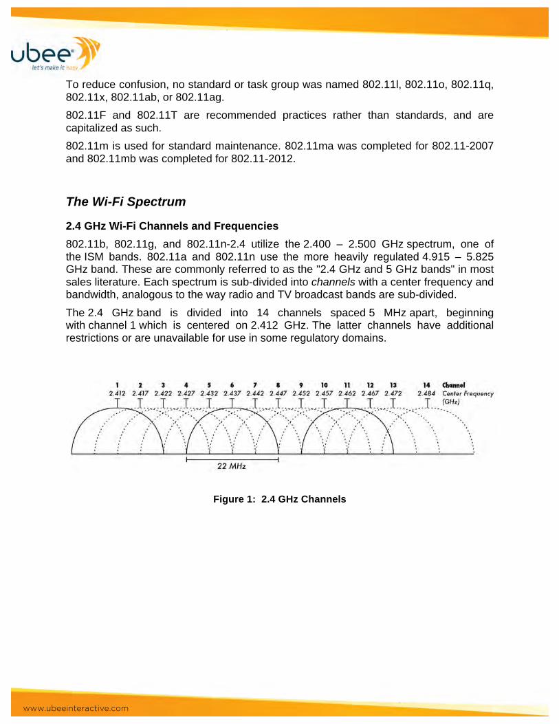
2.4 GHz Wi-Fi Channels and Frequencies 802.11b, 802.11g, and 802.11n-2.4 utilize the 2.400 – 2.500 GHz spectrum, one of the ISM bands. 802.11a and 802.11n use the more heavily regulated 4.915 – 5.825 GHz band. These are commonly referred to as the "2.4 GHz and 5 GHz bands" in most sales literature. Each spectrum is sub-divided into channels with a center frequency and bandwidth, analogous to the way radio and TV broadcast bands are sub-divided. The 2.4 GHz band is divided into 14 channels spaced 5 MHz apart, beginning with channel 1 which is centered on 2.412 GHz. The latter channels have additional restrictions or are unavailable for use in some regulatory domains.
Figure 1: 2.4 GHz Channels

www.ubeeinteractive.com
Figure 2: 2.4GHz Non-Overlapping Channels
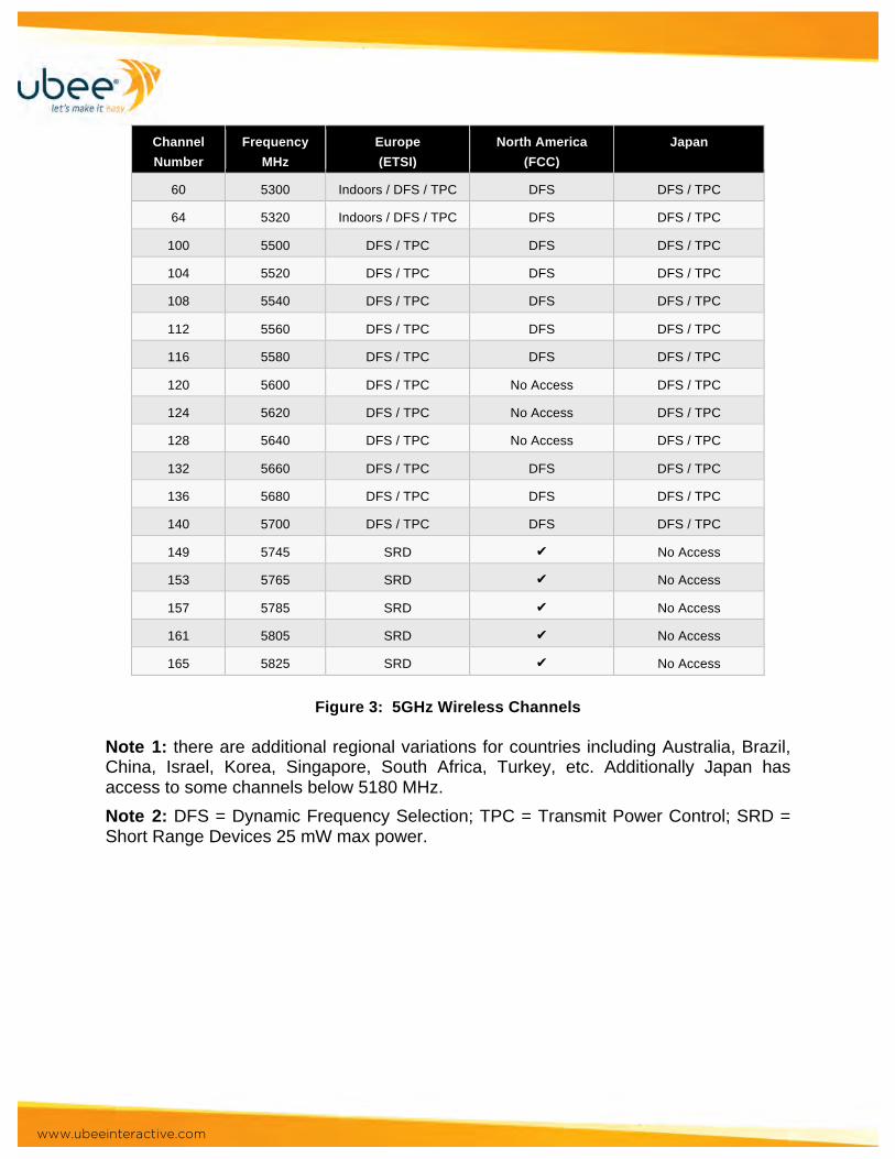
5GHz Wi-Fi Channels and Frequencies As the 2.4 GHz band becomes more crowded, many users are opting to use the 5 GHz ISM band. This band provides more spectrum and is not as widely used by other Wi-Fi appliances such as such as microwave ovens, etc. It will be seen that many of the 5 GHz Wi-Fi channels fall outside the accepted ISM unlicensed band and as a result various restrictions are placed on operation at these frequencies.
Channel Number
Frequency MHz
Europe (ETSI)
North America (FCC)
Japan
36 5180 Indoors ✔ ✔
40 5200 Indoors ✔ ✔
44 5220 Indoors ✔ ✔
48 5240 Indoors ✔ ✔
52 5260 Indoors / DFS / TPC DFS DFS / TPC
56 5280 Indoors / DFS / TPC DFS DFS / TPC
www.ubeeinteractive.com
Channel Number
Frequency MHz
Europe (ETSI)
North America (FCC)
Japan
60 5300 Indoors / DFS / TPC DFS DFS / TPC
64 5320 Indoors / DFS / TPC DFS DFS / TPC
100 5500 DFS / TPC DFS DFS / TPC
104 5520 DFS / TPC DFS DFS / TPC
108 5540 DFS / TPC DFS DFS / TPC
112 5560 DFS / TPC DFS DFS / TPC
116 5580 DFS / TPC DFS DFS / TPC
120 5600 DFS / TPC No Access DFS / TPC
124 5620 DFS / TPC No Access DFS / TPC
128 5640 DFS / TPC No Access DFS / TPC
132 5660 DFS / TPC DFS DFS / TPC
136 5680 DFS / TPC DFS DFS / TPC
140 5700 DFS / TPC DFS DFS / TPC
149 5745 SRD ✔ No Access
153 5765 SRD ✔ No Access
157 5785 SRD ✔ No Access
161 5805 SRD ✔ No Access
165 5825 SRD ✔ No Access
Figure 3: 5GHz Wireless Channels
Note 1: there are additional regional variations for countries including Australia, Brazil, China, Israel, Korea, Singapore, South Africa, Turkey, etc. Additionally Japan has access to some channels below 5180 MHz. Note 2: DFS = Dynamic Frequency Selection; TPC = Transmit Power Control; SRD = Short Range Devices 25 mW max power.

www.ubeeinteractive.com
Wireless Link Overview Spatial Streams Products based 802.11n use a technology known as MIMO (multiple input, multiple output). MIMO utilizes multiple radio chains (and hence multiple antennas) at both the transmitter and the receiver to help increase the throughput and transmit larger amounts of data over the wireless link. At least two chains are required for MIMO functionality; but most systems have more than two chains. Additionally MIMO utilizes a technique called SDM (Spatial Division Multiplexing) that takes advantage of the multiple transmit and receive radio chains. SDM makes it possible to send multiple streams of data simultaneously on the same channel, thereby increasing the data rate and overall throughput. All products certified by the Wi-Fi Alliance for 802.11n must support at least two spatial streams. The IEEE 802.11n specification offers options for up to four spatial streams. In the industry, 802.11n products are typically described in terms of their MIMO attributes, denoted by TxR where “T” is the number of transmit radio chains and “R” is the number of receive radio chains. Most of the 802.11n enterprise access points are either 2×3 or 3×3 systems while most of the early 802.11n clients are 2×2 systems. Other combinations are also possible. In addition to the radio chains (and respective antennas), every 802.11n device must have multiple spatial streams, which is rarely talked about or referred to. Rather than the number of radio chains or antennas, the number of spatial streams is the key factor in determining the capability of the wireless device. The number of streams is a property of the radio chipset. Assuming a clear signal, a two spatial stream link will achieve twice the throughput of a single spatial stream in the same channel. Each spatial stream provides data rates of up to 300 Mbps. The key point is that as long as the system supports 2 spatial streams, you can achieve 300 Mbps data rates, regardless of the number of radios chains.
3 Antennas = 3 Spatial Streams • Typical for Antenna Diversity • MIMO • 3 Transmitters, 3 Receivers, 3 Spatial Streams • 150Mbps max per spatial stream (per antenna) • MCS23 Max PHY Data Rate = 450 Mbps • Example Real Throughput:
o 2x2 Wi-Fi Client o Avg -80 RSSI on client
§ AP 75’ away § RSSI -62 to -86 dBm
o Consistent 36-38 Mbps DS
Figure 4: (3) Spatial Streams
www.ubeeinteractive.com
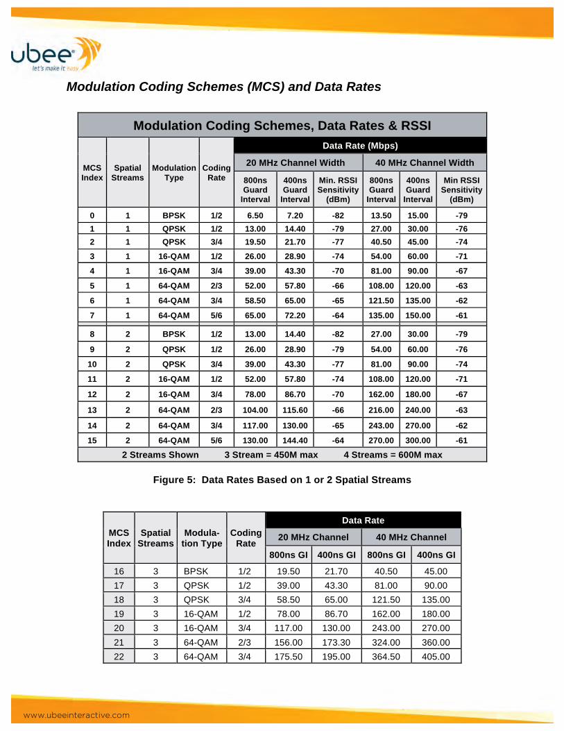
Modulation Coding Schemes (MCS) and Data Rates
Modulation Coding Schemes, Data Rates & RSSI
MCS Index
Spatial Streams
Modulation Type
Coding Rate
Data Rate (Mbps)
20 MHz Channel Width 40 MHz Channel Width
800ns Guard
Interval
400ns Guard
Interval
Min. RSSI Sensitivity
(dBm)
800ns Guard
Interval
400ns Guard
Interval
Min RSSI Sensitivity
(dBm)
0 1 BPSK 1/2 6.50 7.20 -82 13.50 15.00 -79 1 1 QPSK 1/2 13.00 14.40 -79 27.00 30.00 -76 2 1 QPSK 3/4 19.50 21.70 -77 40.50 45.00 -74
3 1 16-QAM 1/2 26.00 28.90 -74 54.00 60.00 -71
4 1 16-QAM 3/4 39.00 43.30 -70 81.00 90.00 -67
5 1 64-QAM 2/3 52.00 57.80 -66 108.00 120.00 -63
6 1 64-QAM 3/4 58.50 65.00 -65 121.50 135.00 -62
7 1 64-QAM 5/6 65.00 72.20 -64 135.00 150.00 -61 8 2 BPSK 1/2 13.00 14.40 -82 27.00 30.00 -79
9 2 QPSK 1/2 26.00 28.90 -79 54.00 60.00 -76
10 2 QPSK 3/4 39.00 43.30 -77 81.00 90.00 -74
11 2 16-QAM 1/2 52.00 57.80 -74 108.00 120.00 -71
12 2 16-QAM 3/4 78.00 86.70 -70 162.00 180.00 -67
13 2 64-QAM 2/3 104.00 115.60 -66 216.00 240.00 -63
14 2 64-QAM 3/4 117.00 130.00 -65 243.00 270.00 -62
15 2 64-QAM 5/6 130.00 144.40 -64 270.00 300.00 -61
2 Streams Shown 3 Stream = 450M max 4 Streams = 600M max
Figure 5: Data Rates Based on 1 or 2 Spatial Streams
MCS Index
Spatial Streams
Modula- tion Type
Coding Rate
Data Rate
20 MHz Channel 40 MHz Channel
800ns GI 400ns GI 800ns GI 400ns GI
16 3 BPSK 1/2 19.50 21.70 40.50 45.00 17 3 QPSK 1/2 39.00 43.30 81.00 90.00 18 3 QPSK 3/4 58.50 65.00 121.50 135.00 19 3 16-QAM 1/2 78.00 86.70 162.00 180.00 20 3 16-QAM 3/4 117.00 130.00 243.00 270.00 21 3 64-QAM 2/3 156.00 173.30 324.00 360.00 22 3 64-QAM 3/4 175.50 195.00 364.50 405.00

www.ubeeinteractive.com
23 3 64-QAM 5/6 195.00 216.70 405.00 450.00 24 4 BPSK 1/2 26.00 28.80 54.00 60.00 25 4 QPSK 1/2 52.00 57.60 108.00 120.00 26 4 QPSK 3/4 78.00 86.80 162.00 180.00 27 4 16-QAM 1/2 104.00 115.60 216.00 240.00 28 4 16-QAM 3/4 156.00 173.20 324.00 360.00 29 4 64-QAM 2/3 208.00 231.20 432.00 480.00 30 4 64-QAM 3/4 234.00 260.00 486.00 540.00 31 4 64-QAM 5/6 260.00 288.80 540.00 600.00
Figure 6: Data Rates Based on 3 or 4 Spatial Stream Systems
Link Data Rates by Channel Width and Spatial Stream
20 MHz Channel 40 MHz Channel 1 stream 2 streams 3 streams 4 streams 1 stream 2 streams 3 streams 4 streams
Data Rate in Mbps 802.11b 2.4 GHz
1, 2, 5.5, 11
802.11n 5 GHz
6, 9, 12, 18, 24, 36, 48, 54
802.11g 2.4 GHz
1, 2, 6, 9, 12, 18, 24, 36, 48, 54
802.11n 2.4 and 5 GHz
6.5, 13, 19.5, 26, 39, 52, 58.5, 65
13, 26, 39, 52, 78, 104, 117, 130
19.5, 39, 58.5, 78, 117, 156, 175.5, 195
26, 52, 78, 104, 156, 208, 234, 260
13.5, 27, 40.5, 54.81, 108, 121.5, 135
27, 54, 81, 108, 162, 216, 243, 270
40.5, 81, 121.5, 162, 243, 324, 364.5, 405
54, 108, 162, 216, 324, 432, 486, 540
802.11n SGI enabled, 2.4 and 5 GHz
7.2, 14.4, 21.7, 28.9, 43.3, 57.8, 65, 72.2
14.4, 28.9, 43.3, 57.8, 86.7, 115.6, 130, 144.4
21.7 43.3, 65, 86.7, 130, 173.3, 231.1, 260, 288.9
28.9, 57.8, 86.7, 115.6, 173.3, 231.1, 260, 288.9
15, 30, 45, 60, 90, 120, 135, 150
30, 60, 90, 120, 180, 270, 360, 405, 450
45, 90, 135, 180, 270, 360, 405, 450
60, 120, 180, 240, 360, 480, 540, 600
Figure 7: Physical Layer Data Rates
Receive Sensitivity The sensitivity of an electronic device (such as a communications system receiver, or detection device) is the minimum magnitude of input signal required to produce a specified output signal having a specified signal-to-noise ratio, or other specified criteria. The theoretical transmission distance that can be achieved between two wireless devices can be calculated from just a few key specifications.
Tx Power = transmission power of device
Actual throughput depends upon signal level, number of spatial streams, error correction overhead, etc.
Good Rule of Thumb: Throughput = ~40-70% of PHY Data Rate

www.ubeeinteractive.com
This is the wireless device's transmission power and is typically measured in dBm (decibel-milliwatts). With greater Tx power, greater transmission distances can be achieved. Data Rate The data rate is the number of bits that are conveyed or processed per unit of time. Since higher data rates require greater transmission power, a wireless device may offer different Tx power specifications for different data rates. Rx Sensitivity = receiver sensitivity of device This is the wireless device's receiver sensitivity and is typically measured in dBm. With greater Rx sensitivity, the device is able to receive weaker signals, which means greater transmission distances can be supported. If two devices have different Tx power and Rx sensitivity specifications, the theoretical transmission distance may be different depending on which direction the data is being transmitted. You will need to consider the Tx power and Rx sensitivity in both directions. In most cases, it is simpler to make sure that every wireless device in your network adheres to the same specifications for Tx power and Rx sensitivity.
Receiver Minimum Input Level Sensitivity
Modulation Rate (R)
Adjacent Channel Rejection
(dB)
Nonadjacent Channel Rejection
(dB)
Minimum Sensitivity (20 MHz channel spacing) (dBm)
Minimum Sensitivity (40 MHz channel spacing) (dBm)
BPSK 1/2 16 32 -82 -79
QPSK 1/2 13 29 -79 -76
QPSK 3/4 11 27 -77 -74
16-QAM 1/2 8 24 -74 -71
16-QAM 3/4 4 20 -70 -67
64-QAM 2/3 0 16 -66 -63
64-QAM 3/4 -1 15 -65 -62
64-QAM 5/6 -2 14 -64 -61
Figure 8 - Receive Sensitivity
Power, Noise, and Link Budgets A link budget is the most important tool for system-level design of wireless systems. It’s a “budget” similar to an accountant’s budget: the sum of gains and losses in various
www.ubeeinteractive.com
parts of the system has to result in satisfactory performance (typically output SNR (signal-to-noise ratio) or BER (bit error rate)). The link budget includes all gains (and losses) from baseband input to baseband output. Since values are gains/losses it is more convenient to add values expressed in dB instead of multiplying and dividing.
Typical Link Budget Elements
The following are the basic quantities included in a link budget:
•• Transmitter Output Power
•• Transmitter Feed Line Losses
•• Transmit Antenna Gain •• Path Loss
•• Other Propagation Losses
•• Receive Antenna Gain •• Receiver Noise Power
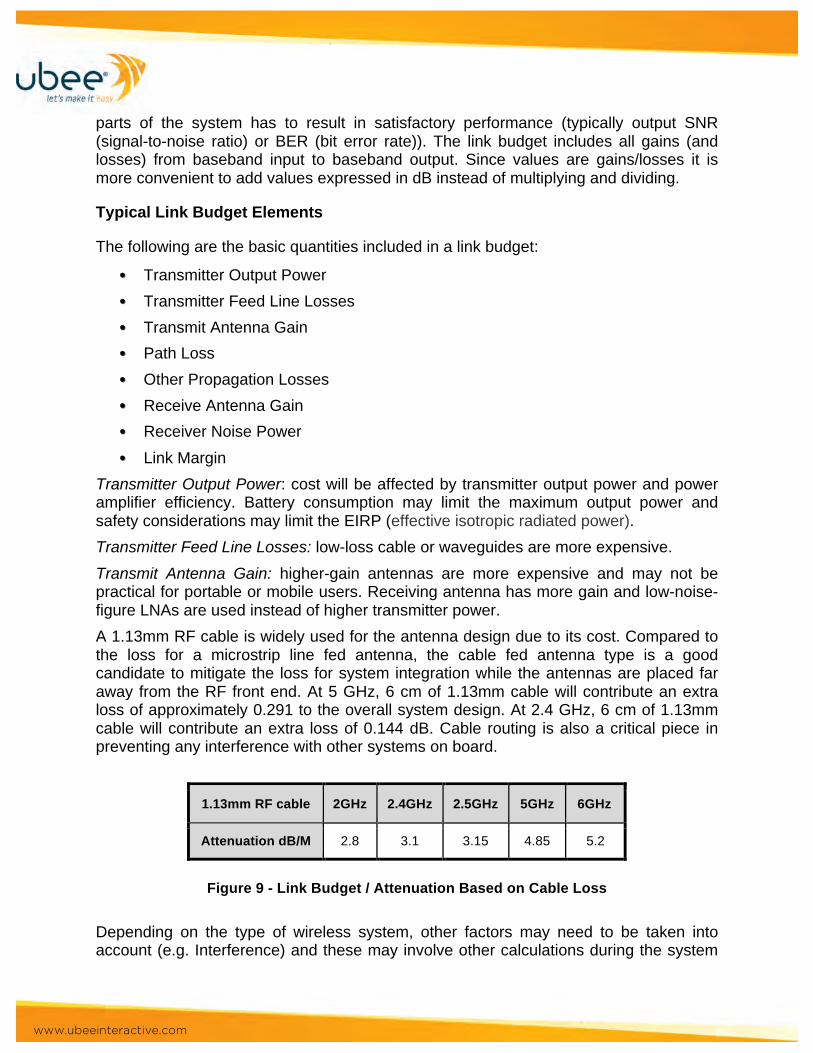
•• Link Margin Transmitter Output Power: cost will be affected by transmitter output power and power amplifier efficiency. Battery consumption may limit the maximum output power and safety considerations may limit the EIRP (effective isotropic radiated power). Transmitter Feed Line Losses: low-loss cable or waveguides are more expensive. Transmit Antenna Gain: higher-gain antennas are more expensive and may not be practical for portable or mobile users. Receiving antenna has more gain and low-noise-figure LNAs are used instead of higher transmitter power. A 1.13mm RF cable is widely used for the antenna design due to its cost. Compared to the loss for a microstrip line fed antenna, the cable fed antenna type is a good candidate to mitigate the loss for system integration while the antennas are placed far away from the RF front end. At 5 GHz, 6 cm of 1.13mm cable will contribute an extra loss of approximately 0.291 to the overall system design. At 2.4 GHz, 6 cm of 1.13mm cable will contribute an extra loss of 0.144 dB. Cable routing is also a critical piece in preventing any interference with other systems on board.
1.13mm RF cable 2GHz 2.4GHz 2.5GHz 5GHz 6GHz
Attenuation dB/M 2.8 3.1 3.15 4.85 5.2
Figure 9 - Link Budget / Attenuation Based on Cable Loss
Depending on the type of wireless system, other factors may need to be taken into account (e.g. Interference) and these may involve other calculations during the system
www.ubeeinteractive.com
design phase. Many system design options will need to be considered, each of which affects one or more of the above gains/losses. The difference between the required SIR/SNR (signal interference ratio/signal-to-noise ratio) and what the link budget predicts is the “margin”. Path Loss: this may be fixed (e.g. a geostationary satellite) or may be a system design parameter (e.g. cell size). For free-space systems we can use the Friis equation, for land-mobile applications we can use statistical models such as Hata-Okumura. Other Propagation Losses: these effects may need to be considered in some applications:
•• Log-Normal Shadowing (land-mobile) •• Diffraction Losses (obstructed paths)
•• Atmospheric Absorption (at high frequencies)
•• Outdoor-to-Indoor Loss (base outside, user indoor) Receiver Antenna Gain: same gain/cost considerations and with transmitter antenna. In some cases using a higher-gain receiving antenna will also reduce interference. Receiver Noise Figure: lower noise figure is more expensive. Many systems are interference limited (the performance is limited by the interference power which is much greater than the thermal noise power) so this may not be an issue. For other systems designs using a low noise figure LNA (low noise amplifier) is the lowest-cost way of closing the link and the cost of the LNA may be a significant part of the system cost Receiver Noise Bandwidth: this will depend on the signal bandwidth, which in turn depends on the data rate and modulation coding scheme gains. A system using FEC may include coding gain in the link budget. Implementation Losses: some link budgets include an implementation loss to account for distortion, intermodulation, phase noise and other degradation introduced by real receivers and transmitters. The objective of the system design phase is to “close the link” (end up with a positive margin) with the lowest (dollar) cost. Link budgets are usually prepared with a spreadsheet so that system design options can be explored.
Variations on the Basic Link Budget: The basic link budget is seldom enough to capture all of the parameters of a real system and usually require different link budgets for forward and reverse channel. You may also need to prepare different link budgets for different modulation schemes or rates, types of users (portable, mobile, fixed), etc. Some values may only be characterized statistically (e.g. path loss). In this case the mean value plus an additional value for the desired percentage coverage or the desired availability (e.g. BER less than 102 over 90% of the service area) is used. In some cases other parameters (e.g. bit rate) can be varied so as to “close” the link; these values must then also be included in the link budget.
www.ubeeinteractive.com
Migrating to 802.11ac IEEE 802.11ac is a wireless computer networking standard in the 802.11 family marketed under the brand name Wi-Fi. It was developed in the IEEE Standards Association process and provides high-throughput wireless local area networks (WLANs) on the 5 GHz band. This specification has expected multi-station WLAN throughput of at least 1 Gbps. This is accomplished with wider RF bandwidth (up to 160 MHz), more MIMO spatial streams (up to 8), multi-user MIMO, and high-density modulation (up to 256-QAM).
Beam Forming Beam forming is a non-proprietary wireless technology that can be integrated across a range of devices, from access points to laptops to smartphones. It greatly improves wireless performance, providing a 2X-3X improvement over previous wireless solutions. Beam forming enables this performance with an innovative approach to how wireless devices connect. In previous generations, wireless was like a light bulb, with a hotspot or access point "radiating" wireless indiscriminately in a set area. Beam forming is like a laser - the hub recognizes the device that needs wireless and focuses the wireless directly where it's needed, whether it's one device or 20. Because of this approach, wireless can also beam around corners and through walls, eliminating previous performance obstacles encountered in large enterprise spaces. In an enterprise environment, not all devices on the network need beam forming to reap the benefits of the technology. An access point with implicit beam forming technology can still directly "beam form" to an end device without it, enabling better performance. A tablet with beam forming technology can better leverage the wireless signal from an access point that does not have beam forming.
Implicit Beam Forming and Explicit Beam Forming: The 802.11n standard defines two types of implementation of transmit beam forming (Tx BF): implicit feedback and explicit feedback. The standard also defines a process called “sounding” of the channel by which the Channel State Information (CSI) is determined. A sounding packet is also defined for this purpose. However, since Tx BF as a technology does not need BFee (beamformee) feedback, sounding packets are an optional feature in the standard, not requiring the BFee to be able to process an NDP or a packet with a staggered preamble, which is the case in legacy systems. In a typical 802.11 system, an access point beam forms to the client and provides increased gain at the client. This leads to higher data rates and reduced number of retries, which in turn can increase the overall capacity of the system and lead to more efficient use of the spectrum. The gain improvement can be up to 12dB, and range improvement can be up to twice that of a system without beam forming—in the case of a 4 transmit antenna system beam forming to a 1 receive antenna system. Also, Tx BF provides maximum benefit in an asymmetrical system, where the number of transmit antennas is different from the number of receive antennas.
www.ubeeinteractive.com
Implicit Beam Forming Implicit feedback Tx BF is based on the assumption that the channel between the BFer (beamformer) and BFee is reciprocal (i.e., identical in uplink and downlink directions). The BFer transmits a training request (TRQ), which is a standard packet in 802.11, and expects to receive a sounding packet in response. Upon receiving the sounding packet, the BFer estimates the receive channel and computes the steering matrix that it will use to steer subsequent transmissions to this BFee in the transmit direction. This method, however, requires computation of correction matrices in order to eliminate any mismatch between the uplink and the downlink channels; in other words, it requires calibration to maintain the reciprocity of the channel.
Explicit Beam Forming In explicit beam forming, the BFee estimates the channel upon transmission of a sounding packet by the BFer. Depending on the implementation, the BFee responds with raw channel estimates or computes the steering matrix and feeds it back to the BFer in compressed or uncompressed forms. In case raw channel estimates are transmitted, the computation of the steering matrix occurs at the BFer. This method provides very reliable steering matrices since the actual channel between the BFer and the BFee is estimated.
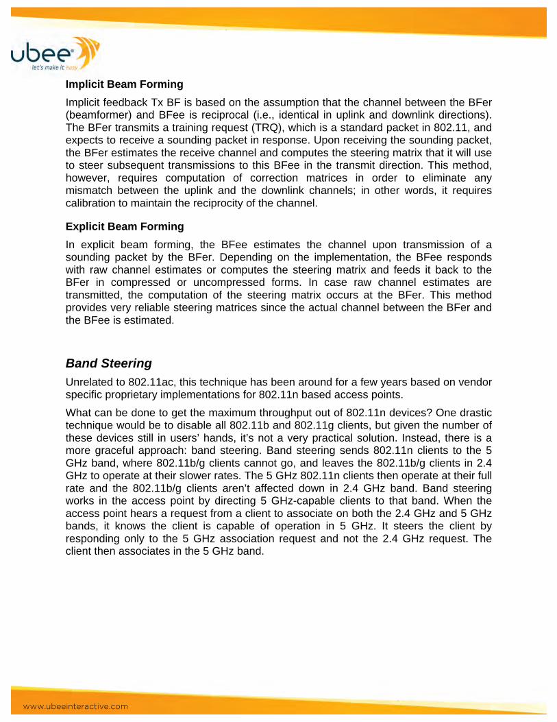
Band Steering Unrelated to 802.11ac, this technique has been around for a few years based on vendor specific proprietary implementations for 802.11n based access points. What can be done to get the maximum throughput out of 802.11n devices? One drastic technique would be to disable all 802.11b and 802.11g clients, but given the number of these devices still in users’ hands, it’s not a very practical solution. Instead, there is a more graceful approach: band steering. Band steering sends 802.11n clients to the 5 GHz band, where 802.11b/g clients cannot go, and leaves the 802.11b/g clients in 2.4 GHz to operate at their slower rates. The 5 GHz 802.11n clients then operate at their full rate and the 802.11b/g clients aren’t affected down in 2.4 GHz band. Band steering works in the access point by directing 5 GHz-capable clients to that band. When the access point hears a request from a client to associate on both the 2.4 GHz and 5 GHz bands, it knows the client is capable of operation in 5 GHz. It steers the client by responding only to the 5 GHz association request and not the 2.4 GHz request. The client then associates in the 5 GHz band.
www.ubeeinteractive.com
Figure 10 - Band Steering for 802.11N devices
Additional MIMO streams & Wider Bandwidth Where 802.11n specified up to four spatial streams for MIMO, 802.11ac extends this to eight streams. The technique is unchanged, but the matrices for calculations become larger, as do the access points – there can be no more spatial streams than the number of transmitting or receiving antennas (whichever is smaller), so full 8SS performance will only be possible where both devices have eight antennas. Without innovative antenna designs, this probably precludes handheld devices, but access points, set top boxes and the like will certainly be able to use multiple streams. As with wider channels, adding spatial streams increases throughput proportionally. Assuming multipath conditions are favorable, two streams offer double the throughput of a single stream, and eight streams increase throughput eight-fold. Some of the most significant throughput gains of 802.11ac are from multi-user MIMO (MU-MIMO). This exploits the same phenomenon of spatial diversity multiplexing (SDM) used in 802.11n, where multiple antennas send separate streams of data independently, although the transmissions occupy the same time and frequency space. This MU-MIMO technique in 802.11ac is also referred to as spatial diversity multiple access (SDMA). MU-MIMO proposes that, instead of considering multiple spatial streams between a given pair of devices, we should be able to use spatial diversity to send multiple data streams between several devices at a given instant. The 802.11ac amendment continues to extend the complexity of its modulation techniques. Building on the rates up to 64- quadrature-amplitude modulation (QAM) of 802.11n, it now extends to 256-QAM. This means that each RF symbol represents one of 256 possible combinations of amplitude (the signal power) versus phase (a shift from the phase of the reference signal). There is very little room for error, as the receiver has to discriminate between 16 possible amplitude levels and 16 phase shift increments – but increases the amount of information each symbol represents from 6 to 8 bits when comparing the top 802.11ac rate to 802.11n before the coding of 5/6 is calculated.

www.ubeeinteractive.com
802.11ac Data Rates Theoretical throughput for single Spatial Stream (in Mbps)
MCS Index
Modulation Type
Coding Rate
20 MHz Channels
40 MHz Channels
80 MHz Channels
160 MHz Channels
800 ns GI
400 ns GI
800 ns GI
400 ns GI
800 ns GI
400 ns GI
800 ns GI
400 ns GI
0 BPSK 1/2 6.5 7.2 13.5 15 29.3 32.5 58.5 65
1 QPSK 1/2 13 14.4 27 30 58.5 65 117 130
2 QPSK 3/4 19 21.7 40.5 45 87.8 97.5 175.5 195
3 16-QAM 1/2 26 28.9 54 60 117 130 234 260
4 16-QAM 3/4 39 43.3 81 90 175.5 195 351 390
5 64-QAM 2/3 52 57.8 108 120 234 260 468 520
6 64-QAM 3/4 58.5 65 121.5 135 263.3 292.5 526.5 585
7 64-QAM 5/6 65 72.2 135 150 292.5 325 585 650
8 256-QAM 3/4 78 86.7 162 180 351 390 702 780
9 256-QAM 5/6 N/A N/A 180 200 390 433.3 780 866.7
Up to 8 streams, MU-MIMO = 6.77G
Figure 11: 802.11ac Data Rates
www.ubeeinteractive.com
Wireless Networking Design Enhancements
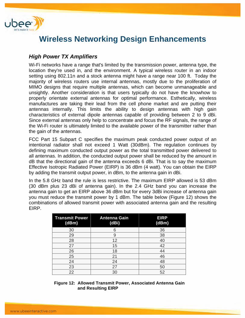
High Power TX Amplifiers Wi-Fi networks have a range that's limited by the transmission power, antenna type, the location they're used in, and the environment. A typical wireless router in an indoor setting using 802.11n and a stock antenna might have a range near 100 ft. Today the majority of wireless routers use internal antennas, mostly due to the proliferation of MIMO designs that require multiple antennas, which can become unmanageable and unsightly. Another consideration is that users typically do not have the knowhow to properly orientate external antennas for optimal performance. Esthetically, wireless manufactures are taking their lead from the cell phone market and are putting their antennas internally. This limits the ability to design antennas with high gain characteristics of external dipole antennas capable of providing between 2 to 9 dBi. Since external antennas only help to concentrate and focus the RF signals, the range of the Wi-Fi router is ultimately limited to the available power of the transmitter rather than the gain of the antennas. FCC Part 15 Subpart C specifies the maximum peak conducted power output of an intentional radiator shall not exceed 1 Watt (30dBm). The regulation continues by defining maximum conducted output power as the total transmitted power delivered to all antennas. In addition, the conducted output power shall be reduced by the amount in dB that the directional gain of the antenna exceeds 6 dBi. That is to say the maximum Effective Isotropic Radiated Power (EIRP) is 36 dBm (4 watt). You can obtain the EIRP by adding the transmit output power, in dBm, to the antenna gain in dBi. In the 5.8 GHz band the rule is less restrictive. The maximum EIRP allowed is 53 dBm (30 dBm plus 23 dBi of antenna gain). In the 2.4 GHz band you can increase the antenna gain to get an EIRP above 36 dBm but for every 3dBi increase of antenna gain you must reduce the transmit power by 1 dBm. The table below (Figure 12) shows the combinations of allowed transmit power with associated antenna gain and the resulting EIRP.
Transmit Power (dBm)
Antenna Gain (dBi)
EIRP (dBm)
30 6 36 29 9 38 28 12 40 27 15 42 26 18 44 25 21 46 24 24 48 23 27 50 22 30 52
Figure 12: Allowed Transmit Power, Associated Antenna Gain
and Resulting EIRP
www.ubeeinteractive.com
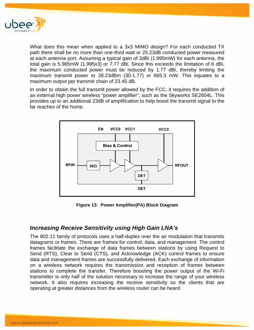
What does this mean when applied to a 3x3 MIMO design? For each conducted TX path there shall be no more than one-third watt or 25.23dB conducted power measured at each antenna port. Assuming a typical gain of 3dBi (1.995mW) for each antenna, the total gain is 5.985mW (1.995x3) or 7.77 dBi. Since this exceeds the limitation of 6 dBi, the maximum conducted power must be reduced by 1.77 dBi, thereby limiting the maximum transmit power to 28.23dBm (30-1.77) or 665.3 mW. This equates to a maximum output per transmit chain of 23.45 dB. In order to obtain the full transmit power allowed by the FCC, it requires the addition of an external high power wireless “power amplifier”, such as the Skyworks SE2604L. This provides up to an additional 23dB of amplification to help boost the transmit signal to the far reaches of the home.
Figure 13: Power Amplifier(PA) Block Diagram
Increasing Receive Sensitivity using High Gain LNA’s The 802.11 family of protocols uses a half-duplex over the air modulation that transmits datagrams or frames. There are frames for control, data, and management. The control frames facilitate the exchange of data frames between stations by using Request to Send (RTS), Clear to Send (CTS), and Acknowledge (ACK) control frames to ensure data and management frames are successfully delivered. Each exchange of information on a wireless network requires the transmission and reception of frames between stations to complete the transfer. Therefore boosting the power output of the Wi-Fi transmitter is only half of the solution necessary to increase the range of your wireless network. It also requires increasing the receive sensitivity so the clients that are operating at greater distances from the wireless router can be heard.
www.ubeeinteractive.com
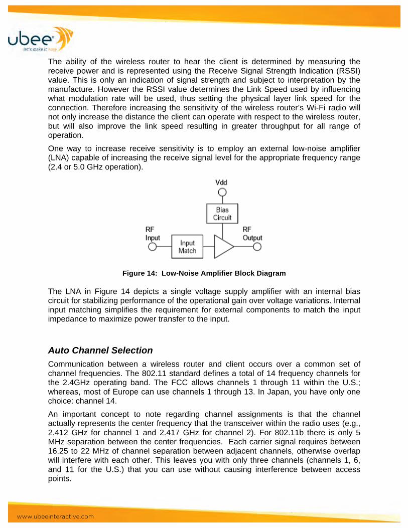
The ability of the wireless router to hear the client is determined by measuring the receive power and is represented using the Receive Signal Strength Indication (RSSI) value. This is only an indication of signal strength and subject to interpretation by the manufacture. However the RSSI value determines the Link Speed used by influencing what modulation rate will be used, thus setting the physical layer link speed for the connection. Therefore increasing the sensitivity of the wireless router’s Wi-Fi radio will not only increase the distance the client can operate with respect to the wireless router, but will also improve the link speed resulting in greater throughput for all range of operation. One way to increase receive sensitivity is to employ an external low-noise amplifier (LNA) capable of increasing the receive signal level for the appropriate frequency range (2.4 or 5.0 GHz operation).
Figure 14: Low-Noise Amplifier Block Diagram
The LNA in Figure 14 depicts a single voltage supply amplifier with an internal bias circuit for stabilizing performance of the operational gain over voltage variations. Internal input matching simplifies the requirement for external components to match the input impedance to maximize power transfer to the input.
Auto Channel Selection Communication between a wireless router and client occurs over a common set of channel frequencies. The 802.11 standard defines a total of 14 frequency channels for the 2.4GHz operating band. The FCC allows channels 1 through 11 within the U.S.; whereas, most of Europe can use channels 1 through 13. In Japan, you have only one choice: channel 14. An important concept to note regarding channel assignments is that the channel actually represents the center frequency that the transceiver within the radio uses (e.g., 2.412 GHz for channel 1 and 2.417 GHz for channel 2). For 802.11b there is only 5 MHz separation between the center frequencies. Each carrier signal requires between 16.25 to 22 MHz of channel separation between adjacent channels, otherwise overlap will interfere with each other. This leaves you with only three channels (channels 1, 6, and 11 for the U.S.) that you can use without causing interference between access points.
www.ubeeinteractive.com
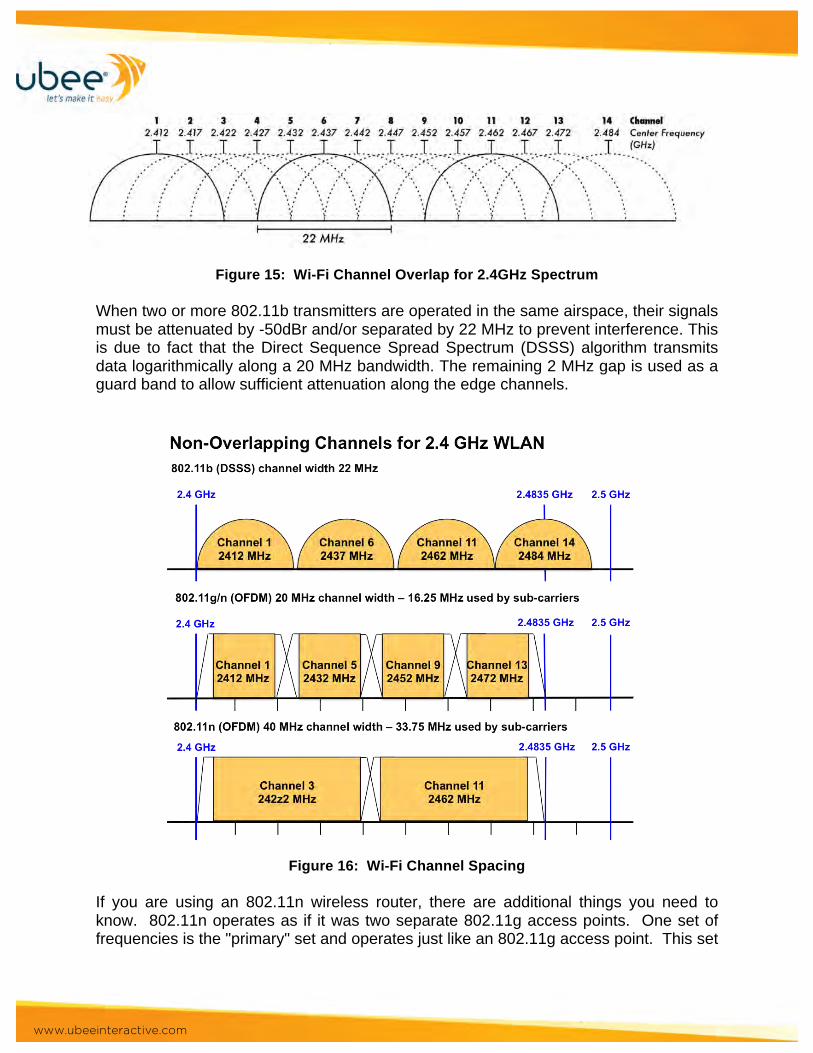
Figure 15: Wi-Fi Channel Overlap for 2.4GHz Spectrum
When two or more 802.11b transmitters are operated in the same airspace, their signals must be attenuated by -50dBr and/or separated by 22 MHz to prevent interference. This is due to fact that the Direct Sequence Spread Spectrum (DSSS) algorithm transmits data logarithmically along a 20 MHz bandwidth. The remaining 2 MHz gap is used as a guard band to allow sufficient attenuation along the edge channels.
Figure 16: Wi-Fi Channel Spacing If you are using an 802.11n wireless router, there are additional things you need to know. 802.11n operates as if it was two separate 802.11g access points. One set of frequencies is the "primary" set and operates just like an 802.11g access point. This set

www.ubeeinteractive.com
of frequencies (the primary lobe) is 20 MHz wide, so any clients that are 802.11g-only will connect to this primary lobe. The 802.11n specification calls for requiring one primary 20 MHz channel as well as a secondary adjacent channel spaced ±20 MHz away. The primary channel (primary lobe) is used for communications with clients incapable of 40 MHz mode. When in 40 MHz mode, the wireless router then selects another 20 MHz wide lobe (secondary lobe) exactly 4 channels away from the primary channel. Now the center frequency is actually the mean of the primary and secondary channels. Thus, for example, if the primary lobe is on channel 9, the access point begins operating a secondary lobe on channel 5. This results in a total of 40 MHz of bandwidth being used, overlapping a total of 8 channels (in this example, channels 3-7 for the secondary lobe, and 7-11 for the primary lobe). This is why 802.11n is generally subject to more interference than 802.11g, because the large slice of the spectrum that it uses can pick up more interference. Interference causes packet loss, which forces retransmissions. This increases delays for all clients trying to access the medium. Wireless routers unable to dynamically change Wi-Fi channels typically lower their physical data (PHY) rate until some level of acceptable transmission is achieved (see Figure 17). However this actually causes more problems — a slower transmit speed means the same packet is in the air longer and therefore more likely to encounter interference. Boosting the data rate and “steering” packets over signal paths that provide better SINR (Signal to Noise and Interference Ratio) helps solve this problem.
Figure 17: Performance Impact by Interference Now that we’ve seen how channels are mapped for the 802.11bgn 2.4GHz band, we can take a look at how Automatic Channel Selection (ACS) works. ACS is a feature some wireless routers use to select the best Wi-Fi channel that will provide the least
www.ubeeinteractive.com
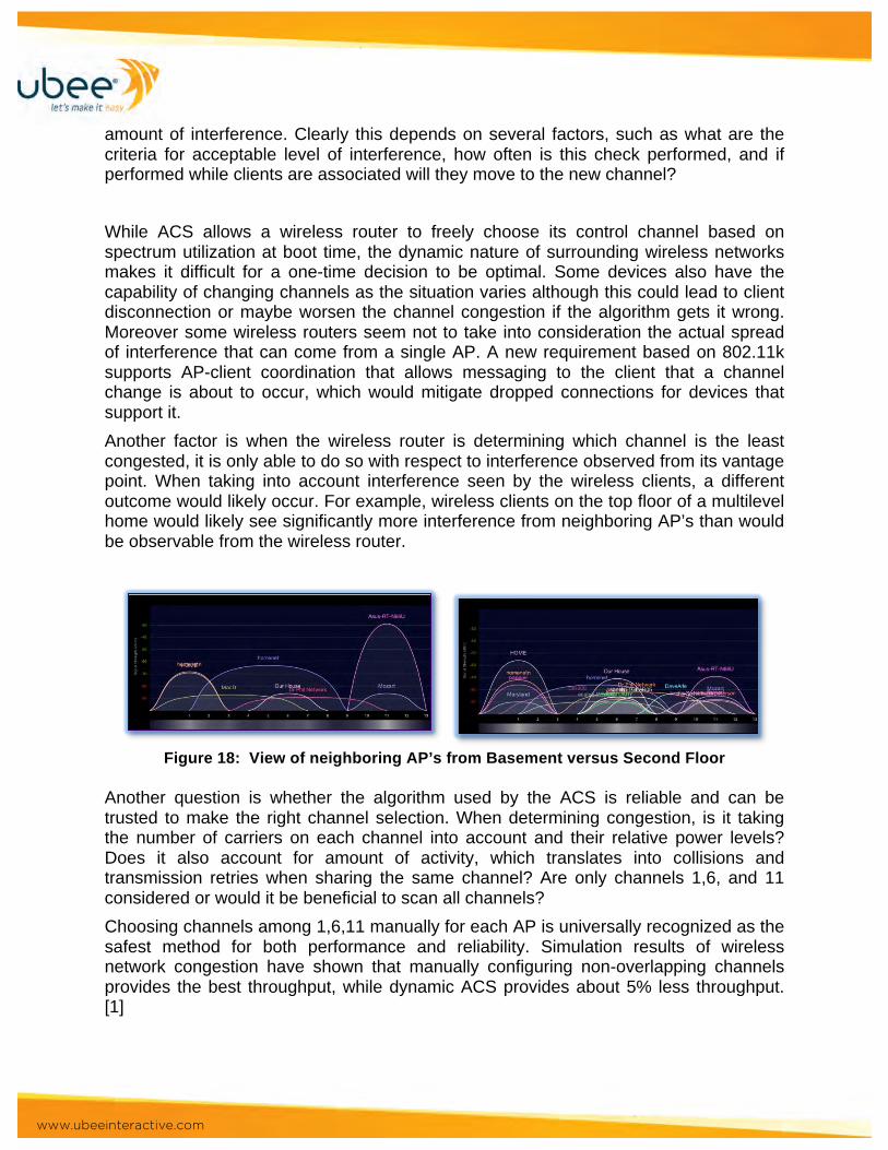
amount of interference. Clearly this depends on several factors, such as what are the criteria for acceptable level of interference, how often is this check performed, and if performed while clients are associated will they move to the new channel? While ACS allows a wireless router to freely choose its control channel based on spectrum utilization at boot time, the dynamic nature of surrounding wireless networks makes it difficult for a one-time decision to be optimal. Some devices also have the capability of changing channels as the situation varies although this could lead to client disconnection or maybe worsen the channel congestion if the algorithm gets it wrong. Moreover some wireless routers seem not to take into consideration the actual spread of interference that can come from a single AP. A new requirement based on 802.11k supports AP-client coordination that allows messaging to the client that a channel change is about to occur, which would mitigate dropped connections for devices that support it. Another factor is when the wireless router is determining which channel is the least congested, it is only able to do so with respect to interference observed from its vantage point. When taking into account interference seen by the wireless clients, a different outcome would likely occur. For example, wireless clients on the top floor of a multilevel home would likely see significantly more interference from neighboring AP’s than would be observable from the wireless router.
Figure 18: View of neighboring AP’s from Basement versus Second Floor
Another question is whether the algorithm used by the ACS is reliable and can be trusted to make the right channel selection. When determining congestion, is it taking the number of carriers on each channel into account and their relative power levels? Does it also account for amount of activity, which translates into collisions and transmission retries when sharing the same channel? Are only channels 1,6, and 11 considered or would it be beneficial to scan all channels? Choosing channels among 1,6,11 manually for each AP is universally recognized as the safest method for both performance and reliability. Simulation results of wireless network congestion have shown that manually configuring non-overlapping channels provides the best throughput, while dynamic ACS provides about 5% less throughput. [1]
www.ubeeinteractive.com
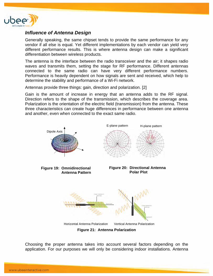
Influence of Antenna Design Generally speaking, the same chipset tends to provide the same performance for any vendor if all else is equal. Yet different implementations by each vendor can yield very different performance results. This is where antenna design can make a significant differentiation between wireless products. The antenna is the interface between the radio transceiver and the air; it shapes radio waves and transmits them, setting the stage for RF performance. Different antennas connected to the same radio can have very different performance numbers. Performance is heavily dependent on how signals are sent and received, which help to determine the stability and performance of a Wi-Fi network. Antennas provide three things: gain, direction and polarization. [2] Gain is the amount of increase in energy that an antenna adds to the RF signal. Direction refers to the shape of the transmission, which describes the coverage area. Polarization is the orientation of the electric field (transmission) from the antenna. These three characteristics can create huge differences in performance between one antenna and another, even when connected to the exact same radio.
Figure 21: Antenna Polarization Choosing the proper antenna takes into account several factors depending on the application. For our purposes we will only be considering indoor installations. Antenna
Figure 19: Omnidirectional Antenna Pattern
Figure 20: Directional Antenna Polar Plot
Dipole Axis
E-plane pattern H-plane pattern
Horizontal Antenna Polarization Vertical Antenna Polarization

www.ubeeinteractive.com
selection is typically determined by range and coverage as the driving factors. In addition, aesthetics should be considered regarding the use of internal versus external antennas. The Multiple-Input Multiple-Output (MIMO) concept, which was made part of the 802.11n standard in the 1990’s, requires multiple antennas to improve communication performance.
Figure 22: MIMO Using External Antennas Some of the latest MIMO designs are using 4 spatial streams (4x4) to support even higher levels of dynamic digital beam forming. Due to the increasing number of antennas required, it has become necessary to move the antennas inside of the enclosure, taking much the same path the cellular phone manufactures did some time ago. Internal antennas have evolved to allow higher levels of efficiency and performance through the use of integrated multi-element and dual polarization designs.
Figure 23: Integrated Internal Antenna Designs The shape of the antenna allows the beam to be formed to achieve higher gain and to provide multiple paths to reduce sensitivity to obstructions and reflections from obstacles. Antennas with several elements can be used to provide polarization diversity and support for dual frequency bands in a single antenna. Antenna integration into the housing of a wireless product requires careful consideration for the placement and type of antenna used. Factors such as performance, manufacturability, enclosure design, and cost will influence the final selection. Options for the placement of internal antennas include mounting on the inside of the housing or on the main PCB.

www.ubeeinteractive.com
Figure 24: Internal Integrated Antenna Placement One unique design utilizes an inverted-F strip integrated on the circuit board of the wireless router using a dual-band F-shaped monopole antenna. The antenna comprises a vertical metal line and two (one upper and one lower) horizontal metal lines of different lengths. The lengths are used for tuning the antenna's first two resonant frequencies to achieve dual-band operation in the 2.4 GHz and 5.0 GHz bands for wireless applications. The antenna is printed on a small region of a microwave substrate that has a compact size of 10×15 mm2 and is fed by a 50 Ω microstrip line printed on the same substrate.[3] The use of internal antennas in the majority of residential wireless routers today has allowed manufactures to deliver products with improved esthetics for in home installation while still being able to provide exceptional performance and range.
Dual-Band Wireless Designs Today’s homes are increasingly accessing the Internet using a wireless connection to multiple devices providing a plethora of services. When selecting a wireless router, there are many options to consider, one being whether to choose a single-band or dual-band router. Though single-band routers are less expensive, dual-band routers offer several important benefits. Dual-band-routers facilitate faster throughput for demanding tasks such as file sharing, streaming large media files, and gaming. A dual-band router enables the user to separate high bandwidth tasks from checking email and browsing the Internet. The user can efficiently browse the Internet on the 2.4-GHz band, while simultaneously streaming media on the 5-GHz band. Operators are taking advantage of this fact by deploying video gateways that will use the 5-GHz band exclusively to distribute content. What is more important than the signals coming from within your home, are the signals coming from outside your home. If you live in an area that is crowded with 2.4GHz signals, such as an apartment complex with a number of neighboring routers and cordless devices, you will be better off with a dual band router. This is especially true if you have already been experiencing signal issues such as under-performing signal strength, sudden drop in signal strength, or disconnects.
www.ubeeinteractive.com
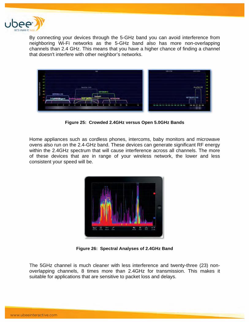
By connecting your devices through the 5-GHz band you can avoid interference from neighboring Wi-Fi networks as the 5-GHz band also has more non-overlapping channels than 2.4 GHz. This means that you have a higher chance of finding a channel that doesn't interfere with other neighbor’s networks.
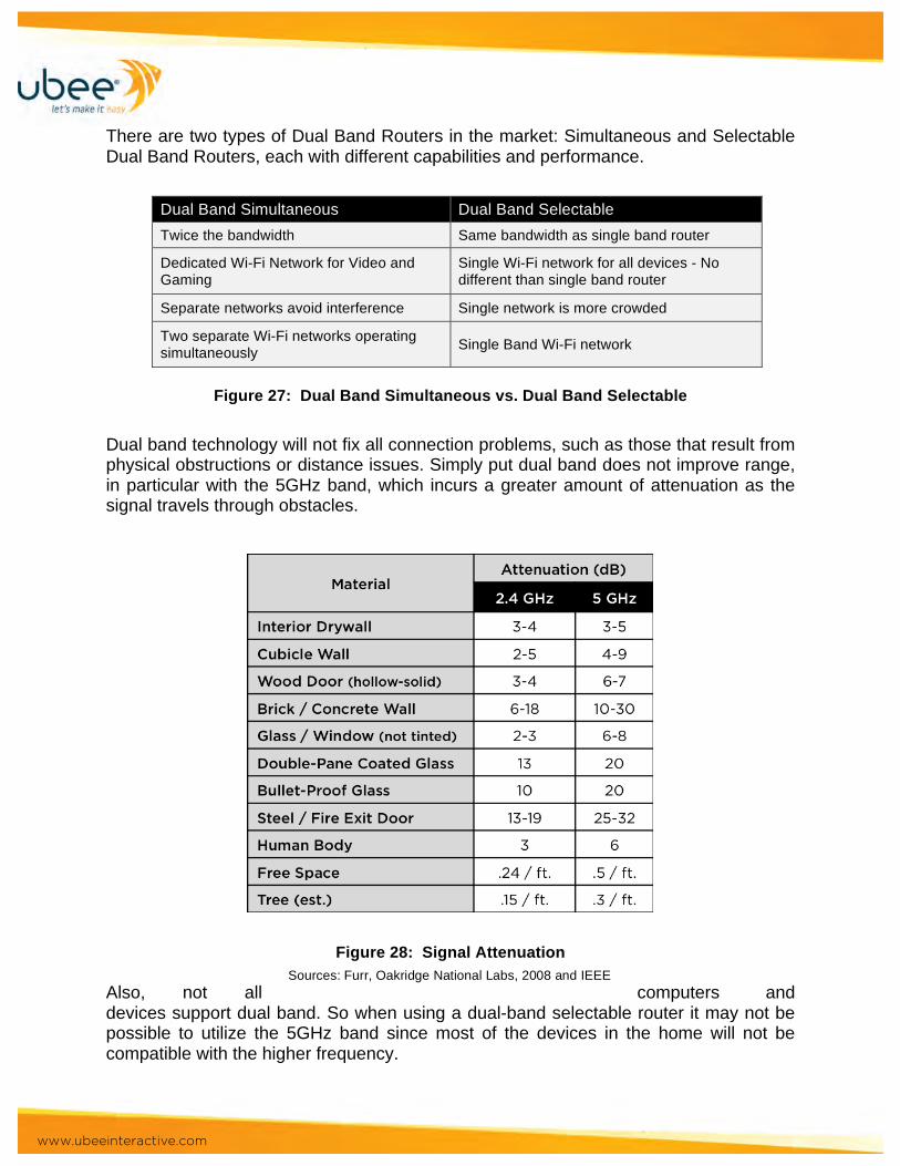
Figure 25: Crowded 2.4GHz versus Open 5.0GHz Bands Home appliances such as cordless phones, intercoms, baby monitors and microwave ovens also run on the 2.4-GHz band. These devices can generate significant RF energy within the 2.4GHz spectrum that will cause interference across all channels. The more of these devices that are in range of your wireless network, the lower and less consistent your speed will be.
Figure 26: Spectral Analyses of 2.4GHz Band The 5GHz channel is much cleaner with less interference and twenty-three (23) non-overlapping channels, 8 times more than 2.4GHz for transmission. This makes it suitable for applications that are sensitive to packet loss and delays.
www.ubeeinteractive.com
There are two types of Dual Band Routers in the market: Simultaneous and Selectable Dual Band Routers, each with different capabilities and performance.
Dual Band Simultaneous Dual Band Selectable Twice the bandwidth Same bandwidth as single band router
Dedicated Wi-Fi Network for Video and Gaming
Single Wi-Fi network for all devices - No different than single band router
Separate networks avoid interference Single network is more crowded
Two separate Wi-Fi networks operating simultaneously Single Band Wi-Fi network
Figure 27: Dual Band Simultaneous vs. Dual Band Selectable
Dual band technology will not fix all connection problems, such as those that result from physical obstructions or distance issues. Simply put dual band does not improve range, in particular with the 5GHz band, which incurs a greater amount of attenuation as the signal travels through obstacles.
Figure 28: Signal Attenuation
Also, not all computers and devices support dual band. So when using a dual-band selectable router it may not be possible to utilize the 5GHz band since most of the devices in the home will not be compatible with the higher frequency.
Sources: Furr, Oakridge National Labs, 2008 and IEEE
www.ubeeinteractive.com
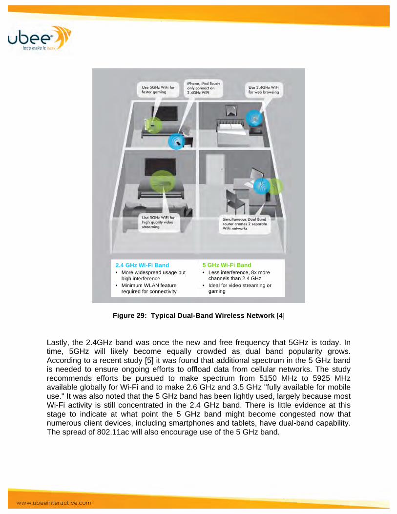
Figure 29: Typical Dual-Band Wireless Network [4] Lastly, the 2.4GHz band was once the new and free frequency that 5GHz is today. In time, 5GHz will likely become equally crowded as dual band popularity grows. According to a recent study [5] it was found that additional spectrum in the 5 GHz band is needed to ensure ongoing efforts to offload data from cellular networks. The study recommends efforts be pursued to make spectrum from 5150 MHz to 5925 MHz available globally for Wi-Fi and to make 2.6 GHz and 3.5 GHz "fully available for mobile use." It was also noted that the 5 GHz band has been lightly used, largely because most Wi-Fi activity is still concentrated in the 2.4 GHz band. There is little evidence at this stage to indicate at what point the 5 GHz band might become congested now that numerous client devices, including smartphones and tablets, have dual-band capability. The spread of 802.11ac will also encourage use of the 5 GHz band.
2.4 GHz Wi-Fi Band • More widespread usage but
high interference • Minimum WLAN feature
required for connectivity
5 GHz Wi-Fi Band • Less interference, 8x more
channels than 2.4 GHz • Ideal for video streaming or
gaming
www.ubeeinteractive.com
Applications Driving Wi-Fi Adoption
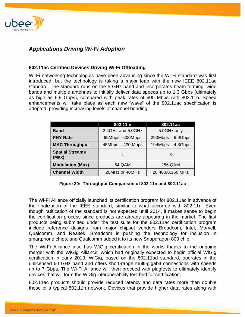
802.11ac Certified Devices Driving Wi-Fi Offloading Wi-Fi networking technologies have been advancing since the Wi-Fi standard was first introduced, but the technology is taking a major leap with the new IEEE 802.11ac standard. The standard runs on the 5 GHz band and incorporates beam-forming, wide bands and multiple antennas to initially deliver data speeds up to 1.3 Gbps (ultimately as high as 6.9 Gbps), compared with peak rates of 600 Mbps with 802.11n. Speed enhancements will take place as each new “wave” of the 802.11ac specification is adopted, providing increasing levels of channel bonding.
802.11 n 802.11ac Band 2.4GHz and 5.0GHz 5.0GHz only PHY Rate 65Mbps - 600Mbps 290Mbps – 6.9Gbps MAC Throughput 45Mbps – 420 Mbps 194Mbps – 4.8Gbps
Spatial Streams (Max) 4 8
Modulation (Max) 64 QAM 256 QAM
Channel Width 20MHz or 40MHz 20,40,80,160 MHz
Figure 30: Throughput Comparison of 802.11n and 802.11ac The Wi-Fi Alliance officially launched its certification program for 802.11ac in advance of the finalization of the IEEE standard, similar to what occurred with 802.11n. Even though ratification of the standard is not expected until 2014, it makes sense to begin the certification process since products are already appearing in the market. The first products being submitted under the test suite for the 802.11ac certification program include reference designs from major chipset vendors Broadcom, Intel, Marvell, Qualcomm, and Realtek. Broadcom is pushing the technology for inclusion in smartphone chips, and Qualcomm added it to its new Snapdragon 800 chip. The Wi-Fi Alliance also has WiGig certification in the works thanks to the ongoing merger with the WiGig Alliance, which had originally expected to begin official WiGig certification in early 2013. WiGig, based on the 802.11ad standard, operates in the unlicensed 60 GHz band and offers short-range multi-gigabit connections with speeds up to 7 Gbps. The Wi-Fi Alliance will then proceed with plugfests to ultimately identify devices that will form the WiGig interoperability test bed for certification. 802.11ac products should provide reduced latency and data rates more than double those of a typical 802.11n network. Devices that provide higher data rates along with
www.ubeeinteractive.com
greater capacity promise to drive even more offloading from cellular to Wi-Fi networks. As 802.11ac is expected to be widely adopted by handset vendors, it is expected to drive adoption in Wi-Fi routers used by hotspot providers. This is important for the big operators that are looking at Wi-Fi as a small cell technology for offloading LTE. Venues, such as convention centers, public hotspots and enterprises will be able to deliver data services to many more users than current technology allows.
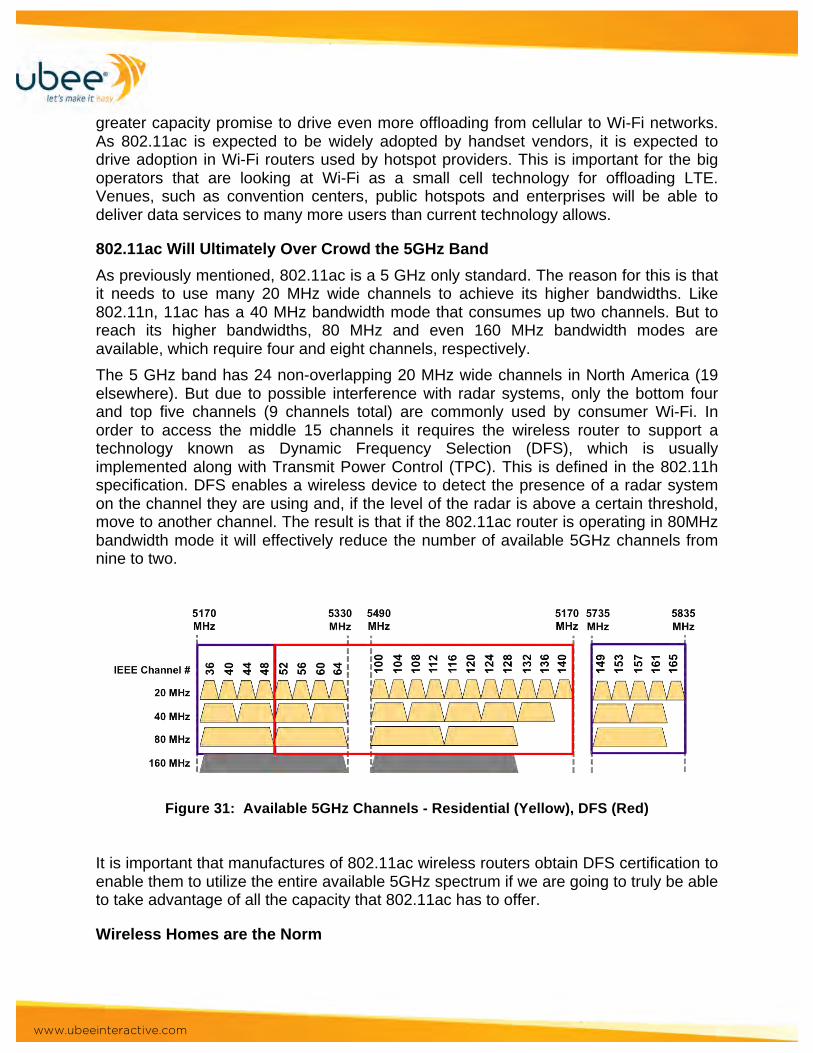
802.11ac Will Ultimately Over Crowd the 5GHz Band As previously mentioned, 802.11ac is a 5 GHz only standard. The reason for this is that it needs to use many 20 MHz wide channels to achieve its higher bandwidths. Like 802.11n, 11ac has a 40 MHz bandwidth mode that consumes up two channels. But to reach its higher bandwidths, 80 MHz and even 160 MHz bandwidth modes are available, which require four and eight channels, respectively. The 5 GHz band has 24 non-overlapping 20 MHz wide channels in North America (19 elsewhere). But due to possible interference with radar systems, only the bottom four and top five channels (9 channels total) are commonly used by consumer Wi-Fi. In order to access the middle 15 channels it requires the wireless router to support a technology known as Dynamic Frequency Selection (DFS), which is usually implemented along with Transmit Power Control (TPC). This is defined in the 802.11h specification. DFS enables a wireless device to detect the presence of a radar system on the channel they are using and, if the level of the radar is above a certain threshold, move to another channel. The result is that if the 802.11ac router is operating in 80MHz bandwidth mode it will effectively reduce the number of available 5GHz channels from nine to two.
Figure 31: Available 5GHz Channels - Residential (Yellow), DFS (Red) It is important that manufactures of 802.11ac wireless routers obtain DFS certification to enable them to utilize the entire available 5GHz spectrum if we are going to truly be able to take advantage of all the capacity that 802.11ac has to offer.
Wireless Homes are the Norm
www.ubeeinteractive.com
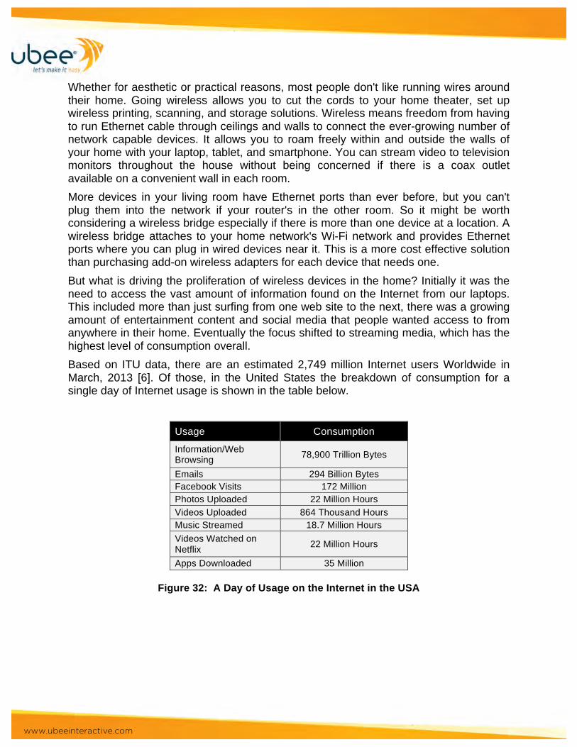
Whether for aesthetic or practical reasons, most people don't like running wires around their home. Going wireless allows you to cut the cords to your home theater, set up wireless printing, scanning, and storage solutions. Wireless means freedom from having to run Ethernet cable through ceilings and walls to connect the ever-growing number of network capable devices. It allows you to roam freely within and outside the walls of your home with your laptop, tablet, and smartphone. You can stream video to television monitors throughout the house without being concerned if there is a coax outlet available on a convenient wall in each room. More devices in your living room have Ethernet ports than ever before, but you can't plug them into the network if your router's in the other room. So it might be worth considering a wireless bridge especially if there is more than one device at a location. A wireless bridge attaches to your home network's Wi-Fi network and provides Ethernet ports where you can plug in wired devices near it. This is a more cost effective solution than purchasing add-on wireless adapters for each device that needs one. But what is driving the proliferation of wireless devices in the home? Initially it was the need to access the vast amount of information found on the Internet from our laptops. This included more than just surfing from one web site to the next, there was a growing amount of entertainment content and social media that people wanted access to from anywhere in their home. Eventually the focus shifted to streaming media, which has the highest level of consumption overall. Based on ITU data, there are an estimated 2,749 million Internet users Worldwide in March, 2013 [6]. Of those, in the United States the breakdown of consumption for a single day of Internet usage is shown in the table below.
Usage Consumption
Information/Web Browsing 78,900 Trillion Bytes
Emails 294 Billion Bytes Facebook Visits 172 Million Photos Uploaded 22 Million Hours Videos Uploaded 864 Thousand Hours Music Streamed 18.7 Million Hours Videos Watched on Netflix 22 Million Hours
Apps Downloaded 35 Million
Figure 32: A Day of Usage on the Internet in the USA

www.ubeeinteractive.com
Explosion in Growth of Internet-Capable Devices Devices used to access the Internet used to be confined to desktop computers and laptops with wired Ethernet connections. Once wireless routers became available and affordable for the home, wireless connectivity became available predominately in laptops and soon was an option for desktops. Today the category of wireless devices includes smartphones, tablets, eBook-Readers, smart TVs, DVD players, game consoles, video streaming players, home security systems, home automation, and the list goes on. Shipments of Internet-enabled consumer electronics will surge to 503.6 million units in 2013, up from 161 million in 2010. In comparison, PC shipments during the same period will amount to 433.7 million, up from 345.4 million.[7] By 2015, shipments of Internet-enabled consumer devices will surpass three-quarters of a billion units, at 780.8 million units, massively exceeding PC shipments of 479.1 million The most popular Internet-enabled devices last year were game consoles, with shipments of 50.5 million units; and televisions, with 40.0 million. However, media tablets are set to grab the top spot in 2011 with projected shipments of 61.9 million, up from 19.7 million last year. The number of smartphones, tablets, laptops and internet-capable phones will exceed the number of humans in 2013, according to a recent Cisco report.[8] Their forecast says that the growth in the use of smartphones and tablets will see more than 7 billion of the world's current population.
•• Mobile video makes up more than half of the data transmitted worldwide, and by 2017 it will make up two-thirds of it.
•• The average amount of data consumed by smartphone users rose 81%, from 189MB per month in 2011 to 342MB monthly in 2012.
•• Smartphones consumed 92% of global mobile data traffic, despite only making up 18% of the handsets in use globally.
•• By 2017, Cisco says, the average smartphone will generate 2.7GB of data traffic a month, almost ten times the traffic today.
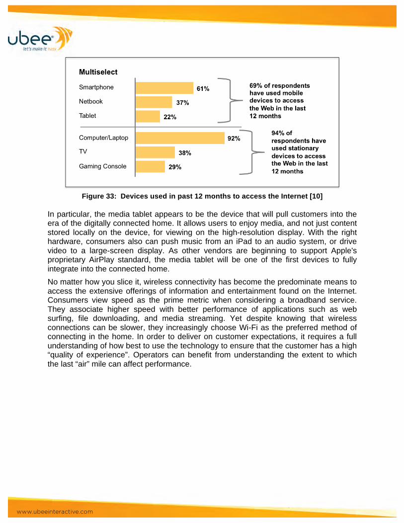
The fastest growth in device adoption over the next five years will be for tablets, Cisco is predicting an average 46% growth year on year, with data growth more than doubling by 113% annually. The next fastest growth will be in "machine to machine modules", which presently make about 5% of internet-enabled devices, growing at 36% annually, and seeing data traffic grow by 89% compound. [9] While smartphones have become the dominant mobile devices for Internet access, the rising popularity of netbooks (37 percent) and tablets (22 percent) shows that the digital consumer seeks an array of features while connecting to the Internet.
www.ubeeinteractive.com
Figure 33: Devices used in past 12 months to access the Internet [10]
In particular, the media tablet appears to be the device that will pull customers into the era of the digitally connected home. It allows users to enjoy media, and not just content stored locally on the device, for viewing on the high-resolution display. With the right hardware, consumers also can push music from an iPad to an audio system, or drive video to a large-screen display. As other vendors are beginning to support Apple's proprietary AirPlay standard, the media tablet will be one of the first devices to fully integrate into the connected home. No matter how you slice it, wireless connectivity has become the predominate means to access the extensive offerings of information and entertainment found on the Internet. Consumers view speed as the prime metric when considering a broadband service. They associate higher speed with better performance of applications such as web surfing, file downloading, and media streaming. Yet despite knowing that wireless connections can be slower, they increasingly choose Wi-Fi as the preferred method of connecting in the home. In order to deliver on customer expectations, it requires a full understanding of how best to use the technology to ensure that the customer has a high “quality of experience”. Operators can benefit from understanding the extent to which the last “air” mile can affect performance.
www.ubeeinteractive.com
References 1. [1] Matthias Ihmig and Peter Steenkiste; Distributed Dynamic Channel Selection in
Chaotic Wireless Networks (White Paper) 2. [2] Ruckus Wireless; White Paper Radios, Antennas and Other Wi-Fi Essentials 3. [3] Shih-Huang Yeh ; Dept. of Electr. Eng., Nat. Sun Yat-Sen Univ., Kaohsiung,
Taiwan ; Kin-Lu Wong; Dual-band F-shaped monopole antenna for 2.4/5.2 GHz WLAN application
4. [4]Netgear PDF “Why choose Simultaneous Dual Band?” 5. [5] EC-commissioned study, written by J. Scott Marcus and John Burns 6. [6]Internet World Stats; http://www.internetworldstats.com/usage.htm 7. [7] IHS iSuppli Consumer Platforms Report; Jean-Pierre Joosting 8. [8] 2013 Guardian News and Media Limite; Charles Arthur 9. [9] Accenture Global Management Consulting, www.accenture.com. 10. [10] Mobile Web Watch Survey, 2012 11. http://en.wikipedia.org/wiki/IEEE_802.11 - cite_ref-part97_1-0 "ARRLWeb: Part 97
- Amateur Radio Service". American Radio Relay League. Retrieved 2010-09-27. 12. http://en.wikipedia.org/wiki/IEEE_802.11 - cite_ref-2 "Wi-Fi (wireless networking
technology)". Encyclopædia Britannica. Retrieved 2010-02-03. 13. http://en.wikipedia.org/wiki/IEEE_802.11 - cite_ref-3 Wolter Lemstra , Vic Hayes ,
John Groenewegen , The Innovation Journey of Wi-Fi: The Road To Global Success, Cambridge University Press, 2010, ISBN 0-521-19971-9
14. http://en.wikipedia.org/wiki/IEEE_802.11 - cite_ref-4 http://news.cnet.com/1200-1070-975460.html
15. http://en.wikipedia.org/wiki/IEEE_802.11 - cite_ref-5 "Wi-Fi Alliance: Organization". Official industry association web site. Retrieved August 23, 2011.
16. "Official IEEE 802.11 working group project timelines". Sept. 19, 2009. Retrieved 2009-10-09.
17. http://en.wikipedia.org/wiki/IEEE_802.11 - cite_ref-7 "Wi-Fi CERTIFIED n: Longer-Range, Faster-Throughput, Multimedia-Grade Wi-Fi® Networks" (registration required). Wi-Fi Alliance. September 2009.
18. "802.11n Delivers Better Range". Wi-Fi Planet. 2007-05-31. 19. "IEEE802.11ac: The Next Evolution of Wi-Fi Standards". 2012-05-11. Retrieved
2012-05-16. 20. http://en.wikipedia.org/wiki/IEEE_802.11 - cite_ref-
10http://www.oreillynet.com/wireless/2003/08/08/wireless_throughput.html

www.ubeeinteractive.com
21. http://en.wikipedia.org/wiki/IEEE_802.11 - cite_ref-ACIisharmfull_11-0 Angelakis, V.; Papadakis, S.; Siris, V.A.; Traganitis, A. (March 2011). "Adjacent channel interference in 802.11a is harmful: Testbed validation of a simple quantification model". Communications Magazine (IEEE) 49 (3): 160–166. doi:10.1109/MCOM.2011.5723815. ISSN 0163-6804
22. http://en.wikipedia.org/wiki/IEEE_802.11 - cite_ref-wndw-pdf_12-0 Wireless Networking in the Developing World: A practical guide to planning and building low-cost telecommunications infrastructure (2nd ed.). Hacker Friendly LLC. 2007. p. 425. page 14
23. http://en.wikipedia.org/wiki/IEEE_802.11 - cite_ref-802.11-2007_13-0 IEEE 802.11-2007
24. http://en.wikipedia.org/wiki/IEEE_802.11 - cite_ref-80211nPR_14-0 "IEEE-SA - News & Events". Standards.ieee.org. Retrieved 2012-05-24.
25. http://en.wikipedia.org/wiki/IEEE_802.11 - cite_ref-802.11-2009_15-0 IEEE 802.11n-2009—Amendment 5: Enhancements for Higher Throughput. IEEE-SA. 29 October 2009.doi:10.1109/IEEESTD.2009.5307322.
26. http://en.wikipedia.org/wiki/IEEE_802.11 - cite_ref-802.11-2012_16-0 "Why did 802.11-2012 renumber clauses?". Matthew Gast, Aerohive Networks. Retrieved 2012-11-17.
27. http://en.wikipedia.org/wiki/IEEE_802.11 - cite_ref-Tri-Band_Chip_Partnership_17-0 "Tri-Band Chip Partnership". BRIGHT SIDE OF NEWS. Retrieved 2012-07-24.
28. http://en.wikipedia.org/wiki/IEEE_802.11 - cite_ref-802.11ad_18-0 "IEEE 802.11ad". Standards.ieee.org. Retrieved 2012-07-24.
29. http://en.wikipedia.org/wiki/IEEE_802.11 - cite_ref-CNAF_19-0 "Cuadro nacional de Atribución de Frecuencias CNAF". Secretaría de Estado de Telecomunicaciones. Archived from the original on 2008-02-13. Retrieved 2008-03-05.
30. http://en.wikipedia.org/wiki/IEEE_802.11 - cite_ref-ART_20-0 "Evolution du régime d’autorisation pour les RLAN". French Telecommunications Regulation Authority (ART). Retrieved 2008-10-26.
31. http://en.wikipedia.org/wiki/IEEE_802.11 - cite_ref-ciscodeployissues_21-0 "Channel Deployment Issues for 2.4 GHz 802.11 WLANs". Cisco Systems, Inc. Retrieved 2007-02-07.
32. http://en.wikipedia.org/wiki/IEEE_802.11 - cite_ref-adjacentchannels_22-0 Garcia Villegas, E.; et al. (2007). "Effect of adjacent-channel interference in IEEE 802.11 WLANs".CrownCom 2007. ICST & IEEE.
33. http://en.wikipedia.org/wiki/IEEE_802.11 - cite_ref-23 IEEE Standard 802.11-2007 page 531
34. http://en.wikipedia.org/wiki/IEEE_802.11 - cite_ref-802.11_Technical_Section_24-0 "802.11 Technical Section". Retrieved 2008-12-15.

www.ubeeinteractive.com
35. http://en.wikipedia.org/wiki/IEEE_802.11 - cite_ref-Frame_Types_25-0 "Understanding 802.11 Frame Types". Retrieved 2008-12-14.
36. http://en.wikipedia.org/wiki/IEEE_802.11 - cite_ref-26 Olivier Bonaventure. "Computer Networking : Principles, Protocols and Practice". Retrieved 2012-07-09.
37. http://en.wikipedia.org/wiki/IEEE_802.11 - cite_ref-27 "IEEE P802.11 - TASK GROUP AC". IEEE. November 2009. Retrieved 2009-12-13.
38. http://en.wikipedia.org/wiki/IEEE_802.11 - cite_ref-28 Fleishman, Glenn (December 7, 2009). "The future of WiFi: gigabit speeds and beyond". Ars Technica. Retrieved 2009-12-13.
39. http://en.wikipedia.org/wiki/IEEE_802.11 - cite_ref-29 Jesse Walker, Chair (May 2009). "Status of Project IEEE 802.11 Task Group w: Protected Management Frames". Retrieved August 23, 2011.
40. http://en.wikipedia.org/wiki/IEEE_802.11 - cite_ref-30http://sviehb.files.wordpress.com/2011/12/viehboeck_wps.pdf
41. http://en.wikipedia.org/wiki/IEEE_802.11 - cite_ref-31 http://www.kb.cert.org/vuls/id/723755 US CERTVulnerability Note VU#723755
42. http://www.radio-electronics.com/info/wireless/wi-fi/80211-channels-number-frequencies-bandwidth.php
43. Creative Commons Attribution-ShareAlike Licinse 44. http://blog.merunetworks.com 45. http://www.ece.ubc.ca 46. http://www.moxa.com 47. http://en.wikipedia.org/wiki/IEEE_802.11ac 48. http://meraki.cisco.com 49. http://www.arubanetworks.com 50. IEEE 802.11: Wireless LAN Medium Access Control (MAC) and Physical Layer
(PHY) Specifications. (2012 revision). IEEE-SA. 5 April 2012. doi:10.1109/IEEESTD.2012.6178212.
51. http://en.wikipedia.org/wiki/IEEE_802.11 52. IEEE 802.11k-2008—Amendment 1: Radio Resource Measurement of Wireless
LANs. IEEE-SA. 12 June 2008. doi:10.1109/IEEESTD.2008.4544755. 53. IEEE 802.11r-2008—Amendment 2: Fast Basic Service Set (BSS)
Transition. IEEE-SA. 15 July 2008. doi:10.1109/IEEESTD.2008.4573292. 54. IEEE 802.11y-2008—Amendment 3: 3650–3700 MHz Operation in USA. IEEE-SA.
6 November 2008. doi:10.1109/IEEESTD.2008.4669928.
www.ubeeinteractive.com
802.11 Specifications 802.11a: An IEEE standard for a wireless network that operates at 5 GHz with rates up to 54Mbps. 802.11b: An IEEE standard for a wireless network that operates at 2.4 GHz with rates up to 11Mbps. 802.11d: An IEEE specification that allows for configuration changes at the Media Access Control layer (MAC layer) level to comply with the rules of the country in which the network is to be used. 802.11e: An IEEE standard that adds Quality of Service (QoS) features and multimedia support to the existing 802.11b, 802.11g, and 802.11a wireless networks. 802.11g: An IEEE standard for a wireless network that operates at 2.4 GHz Wi-Fi with rates up to 54Mbps. 802.11h: 802.11h supports Dynamic Frequency Selection(DFS) and Transmit Power Control(TPC) requirements to ensure coexistence between Wi-Fi and other types of radio frequency devices in the 5 GHz band. 802.11i: An IEEE standard specifying security mechanisms for 802.11 networks. 802.11i makes use of the Advanced Encryption Standard (AES) block cipher. The standard also includes improvements in key management, user authentication through 802.1X and data integrity of headers. 802.11j: An IEEE specification for wireless networks that incorporates Japanese regulatory requirements concerning wireless transmitter output power, operational modes, channel arrangements and spurious emission levels. 802.11n: A taskgroup of the IEEE 802.11 committee whose goal is to define a standard for high throughput speeds of at least 100Mbps on wireless networks. The standard is expected to be ratified by 2007. Some proposals being fielded by the taskgroup include designs for up to 540 Mbps. Multiple-Input-Multiple-Output (MIMO) technology, using multiple receivers and multiple transmitters in both the client and access point to achieve improved performance is expected to form the basis of the final specification. 802.1X: A standard for port-based authentication, first used in wired networks, that was adapted for use in enterprise WLANs to address security flaws in WEP, the original security specification for 802.11 networks. 802.1X provides a framework for authenticating users and controlling their access to a protected network and dynamic encryption keys to protect data privacy.
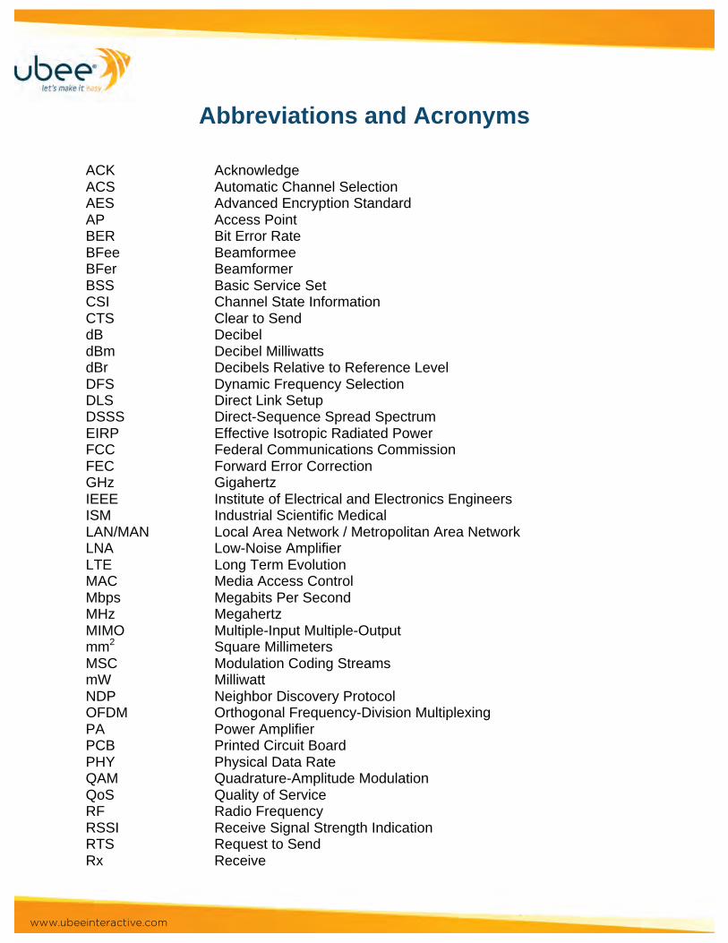
www.ubeeinteractive.com
Abbreviations and Acronyms ACK Acknowledge ACS Automatic Channel Selection AES Advanced Encryption Standard AP Access Point BER Bit Error Rate BFee Beamformee BFer Beamformer BSS Basic Service Set CSI Channel State Information CTS Clear to Send dB Decibel dBm Decibel Milliwatts dBr Decibels Relative to Reference Level DFS Dynamic Frequency Selection DLS Direct Link Setup DSSS Direct-Sequence Spread Spectrum EIRP Effective Isotropic Radiated Power FCC Federal Communications Commission FEC Forward Error Correction GHz Gigahertz IEEE Institute of Electrical and Electronics Engineers ISM Industrial Scientific Medical LAN/MAN Local Area Network / Metropolitan Area Network LNA Low-Noise Amplifier LTE Long Term Evolution MAC Media Access Control Mbps Megabits Per Second MHz Megahertz MIMO Multiple-Input Multiple-Output mm2 Square Millimeters MSC Modulation Coding Streams mW Milliwatt NDP Neighbor Discovery Protocol OFDM Orthogonal Frequency-Division Multiplexing PA Power Amplifier PCB Printed Circuit Board PHY Physical Data Rate QAM Quadrature-Amplitude Modulation QoS Quality of Service RF Radio Frequency RSSI Receive Signal Strength Indication RTS Request to Send Rx Receive
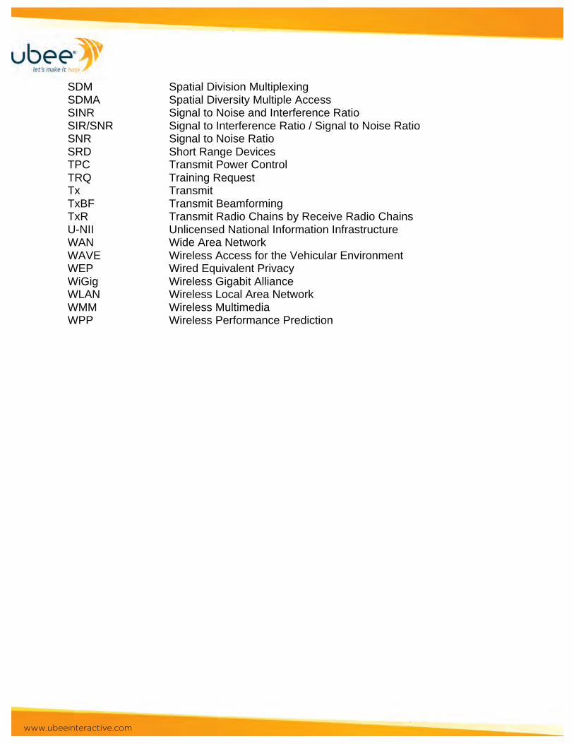
www.ubeeinteractive.com
SDM Spatial Division Multiplexing SDMA Spatial Diversity Multiple Access SINR Signal to Noise and Interference Ratio SIR/SNR Signal to Interference Ratio / Signal to Noise Ratio SNR Signal to Noise Ratio SRD Short Range Devices TPC Transmit Power Control TRQ Training Request Tx Transmit TxBF Transmit Beamforming TxR Transmit Radio Chains by Receive Radio Chains U-NII Unlicensed National Information Infrastructure WAN Wide Area Network WAVE Wireless Access for the Vehicular Environment WEP Wired Equivalent Privacy WiGig Wireless Gigabit Alliance WLAN Wireless Local Area Network WMM Wireless Multimedia WPP Wireless Performance Prediction