understanding route redistribution & filtering
TRANSCRIPT

Revision B ©2013, Palo Alto Networks, Inc. www.paloaltonetworks.com
Understanding Route Redistribution & Filtering
When to Redistribute and Filter
PAN-OS 5.0

©2013, Palo Alto Networks, Inc. [2]
Contents
OverviewOverviewOverviewOverview ................................................................................................................................................................................................................................................................................................................................................................................................................................................................................................................................................................................................................................................................................................................................................................................ 3333
Route RedistributionRoute RedistributionRoute RedistributionRoute Redistribution............................................................................................................................................................................................................................................................................................................................................................................................................................................................................................................................................................................................................................................................................................................ 3333
Route FiRoute FiRoute FiRoute Filteringlteringlteringltering................................................................................................................................................................................................................................................................................................................................................................................................................................................................................................................................................................................................................................................................................................................................................ 3333
Administrative Distance and Route MetricAdministrative Distance and Route MetricAdministrative Distance and Route MetricAdministrative Distance and Route Metric ............................................................................................................................................................................................................................................................................................................................................................................................................................................................................................................................................................................ 3333
Administrative Distance .......................................................................................................................................................................... 3
Route Metric .......................................................................................................................................................................................... 5
PANPANPANPAN----OS Redistribution ProfilesOS Redistribution ProfilesOS Redistribution ProfilesOS Redistribution Profiles........................................................................................................................................................................................................................................................................................................................................................................................................................................................................................................................................................................................................................................ 6666
Route Redistribution & Filtering ExamplesRoute Redistribution & Filtering ExamplesRoute Redistribution & Filtering ExamplesRoute Redistribution & Filtering Examples ........................................................................................................................................................................................................................................................................................................................................................................................................................................................................................................................................................................ 7777
Redistributing Static Routes into OSPF .................................................................................................................................................. 7
Redistributing Connected Routes into OSPF ....................................................................................................................................... 10
Filtering Routes with the Redistribution Profile .................................................................................................................................... 11
Redistributing Host Addresses into OSPF and BGP ............................................................................................................................ 12
Redistributing Default Route Through an OSPF Not-So-Stubby-Area (NSSA) .................................................................................... 13
Redistributing RIP Routes into OSPF .................................................................................................................................................. 14
Redistributing Summarized Routes to BGP.......................................................................................................................................... 16
Redistributing Static Routes to Select BGP Peers ................................................................................................................................. 18
Redistributing Routes Between BGP and OSPF .................................................................................................................................. 19
Redistributing Connected Routes Into BGP for Redistribution to OSPF ......................................................................................... 20
Filtering BGP Routes Coming from BGP Peers ............................................................................................................................... 23
Redistributing Routes From BGP to OSPF ...................................................................................................................................... 25
Redistributing Routes from OSPF to BGP ....................................................................................................................................... 26
SummarySummarySummarySummary .................................................................................................................................................................................................................................................................................................................................................................................................................................................................................................................................................................................................................................................................................................................................................................... 28282828

©2013, Palo Alto Networks, Inc. [3]
Overview Layer 3 networks are often comprised of one or more dynamic routing protocols mixed with static and connected routes between one or multiple routers. In order to ensure proper routing or to restrict network access to specific networks within the enterprise or between peers, redistribution and filtering of routes is often required. This paper will concentrate on some of the more common scenarios for route redistribution and filtering and illustrate how PAN-OS configures them.
Route Redistribution Networks that are running multiple dynamic routing protocols (DRP) such as RIPv2, OSPF, or BGP may need to redistribute routes into the dynamic routing protocols for the following reasons:
1. Injecting static routes into the dynamic routing protocol to make specific networks available – such as legacy static prefixes into OSPF.
2. Advertising locally connected routes into a dynamic routing protocol – such as a private lab network defined separately from the dynamically routed network.
3. Redistributing routes from one dynamic routing protocol to another – such as from RIP to OSPF or from BGP to OSPF.
4. Redistributing a host IP address into a dynamic routing protocol – such as advertising a route to a specific server in another network not belonging to the DRP’s autonomous system (AS).
5. Manipulating externally learned route priorities in OSPF – such as EXT1 and EXT2 route types.
Route Filtering Route filtering is often used to filter the route prefixes that are advertised between one routing protocol to another or from one autonomous system to another. Examples of common route filtering use cases include:
1. Filtering specific network prefixes from being exported or imported from a dynamic routing protocol – such as filtering out overlapping network ranges from RIP to OSPF.
2. Limiting the route prefixes advertised to an ISP running BGP. 3. Accepting only the default route from your ISP – such as importing only the BGP default route from your ISP(s)
and rejecting all other network prefixes. 4. Advertising the local network prefix to your ISP peer – such as advertising your IANA assigned networking prefix
to your BGP ISP peer. 5. Performing Route Map filtering in BGP to prioritize traffic between multiple ISPs – such as changing the Local
Preference on inbound paths from ISP A to allow it to be selected as the preferred path. 6. Excluding specific networks from the routing table so they’re not advertised throughout the AS. 7. Summarizing routes from one AS to be advertised into another AS – such as aggregating many longer network
prefixes in OSPF to a summary network prefix to be advertised into BGP
Administrative Distance and Route Metric When routing between different autonomous systems (such as RIP and OSPF) or within a single autonomous system, the administrative distance and route metric can be tuned to manipulate the route selection process. Route selection is the process used by the routing engine to analyze, weigh, and select the “best paths” from the route table (also known as the routing information base or RIB) to place into the forwarding table. The RIB contains “all known” paths/routes to each destination and the forwarding table contains the best path or route to the destination.
Administrative Distance Most routing protocols have their own distinctive routing structures and metrics which are used to prioritize routes. When two or more protocols are used within the same physical network, incompatibilities arise between the routed environments or autonomous systems. The ability to exchange routing information between autonomous systems to facilitate the best path selection across multiple protocols becomes critical in these environments and that’s what the administrative distance is designed to do.

©2013, Palo Alto Networks, Inc. [4]
The Administrative Distance is used to define the best path when there are multiple paths from multiple protocols to the same destination. Routers assign administrative distances to routes in the RIB and depending on the protocol or route type, specific default administrative values are assigned. PAN-OS assigns the following default administrative distances. Note: Administrative distances are set from the Network > Virtual Routers > vr_name > General screen and are applicable to the virtual router.
Route Type or Protocol Default Administrative Distance
Static 10 OSPF Internal 30 OSPF External 110 Internal BGP (IBGP) 200 External BGP (EBGP) 20 RIP 120
Note: An administrative distance of 255 will cause the router to “disbelieve” the route entirely and it will be excluded from the route selection process. In PAN-OS v5.0.0, the administrative distance value that can be set ranges from 10 to 240. The lower the administrative value, the higher the path’s priority. For example, if there are multiple routes to the same destination using three different routing methods and each route type had the following administrative values: Static Route administrative distance: 10 OSPF Int Route administrative distance: 30 RIP Route administrative distance: 120 The static route would be the preferred path and this route will be selected from the RIB and placed into the forwarding table as the best path. In a redistribution case, if you wanted the firewall to use the OSPF learned route (default value 30) over the statically assigned route (default value 10) to the same destination, you would increase the administrative distance for the static route to a value greater than 30.
Example of the “Virtual Router > General” Screen

©2013, Palo Alto Networks, Inc. [5]
Route Metric The Route Metric is similar to administrative distance in helping to select or predict the best route. However, route metrics are only applicable within a single routing protocol and are not used when forwarding traffic through multiple protocols – the administrative distance is used for multi-protocols. The route metric on Palo Alto Networks firewalls can be set to determine route selection when there are multiple paths to the same destination. Lower metric values are preferred over higher values. When determining what value to set the metric to, administrators should consider the different characteristics of their networks. Decision points such as bandwidth, network delay, hop count, path cost, load, reliability, monetary cost, and even MTU can be used to influence the metric’s value. The routing information base contains all possible paths to each destination along with the calculated route metric values and the best or preferred route with the lowest metric is selected for inclusion in the forwarding table. With PAN-OS 5.0.0, the firewall will only support one path it believes to be the best path to each destination. The following is an example of the routing information base (route table) from a Palo Alto Networks firewall.
Example of the “show routing route” command (CLI) Note the “metric” column which displays the route metric value for each of the destinations and the values that are assigned to the various route types. Locally connected routes are assigned a value of zero as they are always preferred over other learned routes that external to the router. Values that can be assigned to the route metric can differ between routing protocols. For example, RIPv2 will have a much lower metric range than OSPF because its metric is based on a maximum number of hops. Static routes have a different range because they can be redistributed into different protocols. As mentioned, different protocols use different path selection schemes and the metric can be one of the ways the preferred path is selected. Protocols such as BGP can use other mechanisms such as local preference, MED, or weight to affect route selection as well. The table below illustrates some of the valid ranges supported by PAN-OS.

©2013, Palo Alto Networks, Inc. [6]
Protocol or Route Type Valid Range Static Route Metric 1 - 65535 OSPF Interface Metric 1 – 65535 BGP Local Preference 0 - 4294967295 BGP MED Metric 0 - 4294967295 BGP Weight 0 – 65535 RIPv2 Metric 1 – 16
When redistributing routes from one protocol to another, a valid metric value that is suitable for the destination protocol must be used. For example, if you are redistributing OSPF routes into a RIP AS and you would like all routers within the RIP AS to be able to reach OSPF destinations, a lower metric should be used. Because RIP can only have a maximum of 15 hops (with the 16th hop considered unreachable) setting the OSPF routes to a high value (such as 10) limits the redistributed routes’ range within the RIP AS.
PAN-OS Redistribution Profiles Palo Alto Networks firewalls provide a flexible, profile-based approach for route redistribution and filtering between protocols, static routes, connected routes, and hosts. Without redistribution profiles, each protocol functions on its own and does not exchange any route information with other protocols running on the same virtual router. Redistribution profiles are the only way to exchange routing information between protocols. When multiple redistribution profiles are used, the ordering is important. The “priority” field is used to prioritize the redistribution profiles to allow redistribution inclusion or exclusion to take place when you want to include some routes in the redistribution and exclude others. The lower priority numbers are matched first and the priority value can range from 1 to 255.
To include routes to be redistributed from one protocol to another, select the “Redist” radio button. The “New Metric” field can be used to assign a route metric value to the routes being redistributed. To exclude routes from the redistribution event, select the “No Redist” radio button.
Example of Redistribution Profile Screen Note: When multiple redistribution profiles are defined, the “more specific” profiles should be place ahead of the “general” profiles using the priority value. A lower priority value places the profile earlier in the execution order. For example a redistribution profile with a priority value =1 will be executed before a profile with a priority = 5.

©2013, Palo Alto Networks, Inc. [7]
Route Redistribution & Filtering Examples This section provides examples of route redistribution use cases and shows how to configure the Palo Alto Networks firewall to perform the necessary task. By examining each of these examples, many other types of redistribution profiles can be created to control how routes are populated within each protocol to accurately define the routing environment. In our examples, OSPF is used in many of the illustrations because it is one of the most popular enterprise routing protocols. However, other dynamic routing protocols can easily be substituted.
Redistributing Static Routes into OSPF The need to redistribute a static route into a dynamic routing protocol like OSPF is fairly common use case. For example, when Company ABC was small, it used static routes to control the routing between its test lab and corporate network segments. As the company grew, many new networks were added on the corporate side and OSPF was implemented to help scale the network more efficiently. In order to allow corporate users to access the test lab networks (which are maintained with static routes), the network administrator needs to redistribute the desired test lab static routes into the OSPF environment. In this example, we will show how static routes are configured on the firewall and how they are redistributed into the OSPF autonomous system using redistribution profiles. Step 1: Create the required static routes on the firewall’s virtual router to allow the firewall access to these networks. Access the Network > Virtual Routers > vr_name > Static Routes > Add feature to add a new static route.
Assign the desired route metric - the lower the value, the higher the priority for route selection into the Forwarding Table (FIB). This example uses a metric of “10”. Step 2: Create a new Redistribution Profile to inject the static route(s) into the OSPF AS. Access the Network > Virtual Routers > vr_name > Redistribution Profiles > Add feature to create a new redistribution profile. In this example, the “static” redistribution profile will use a higher metric value of “20” and change the static route’s metric of “10”. If there are multiple paths to get to the same routing prefix, the lowest metric route will be selected for inclusion in the forwarding table.

©2013, Palo Alto Networks, Inc. [8]
Step 3: Instruct OSPF to “export” the redistribution profile containing the static route. Access the Network > Virtual Routers > vr_name > OSPF > Export Rules feature to select the redistribution profile to export. Select the redistribution profile created in step 2 and set the New Path Type. In OSPF, external routes brought into the autonomous system can be one of two types: External Type 1 or External Type 2. • External Type 1 (Ext 1) routes calculate the total cost using the internal and external OSFP metrics. • External Type 2 (Ext 2) routes calculate the total cost using only the external metrics, no internal metrics are used.
External Type 2 is the default.
Note: The term “export” may seem a bit confusing if you’re not familiar with the redistribution terminology as it looks like we’re importing a static route from the outside into the OSPF environment.
Step 4: Commit the changes and verify the RIB and forwarding tables with the “show routing route” and “show routing fib” commands. You can also use the “More Runtime Stats” option from the Web user interface. The routing table for the local device that performed the redistribution will contain only the static routes. The firewall or adjacent router will contain the static route prefixes redistributed into the OSPF AS.
Example of the “show routing route” command on the local firewall that performed the static to OSPF redistribution

©2013, Palo Alto Networks, Inc. [9]
Example of the “show routing route” command on the adjacent firewall that shows the static to OSPF redistribution. Notice the new metric value of “20” that was set by the redistribution policy.
Example of the “show routing fib” command on the local firewall’s forwarding table

©2013, Palo Alto Networks, Inc. [10]
Redistributing Connected Routes into OSPF In many enterprise environments, specific interfaces are configured to participate in a dynamic routing protocol such as OSPF. However, there are often other interfaces that have been configured with one or more IP addresses that are not part of the dynamic routing environment. These networks might have been part of a corporate acquisition or belong to legacy networks that were in place before OSPF was implemented. In these cases, it may be necessary to redistribute the “connected routes” back into the dynamic routing protocol so they can be accessed throughout the OSPF AS. Step 1: Create a new Redistribution Profile to inject the connected route into the OSPF AS. Access the Network > Virtual Routers > vr_name > Redistribution Profiles > Add feature to create a new redistribution profile. • Select “connect” as the redistribution type and
select the “Redist” radio button to instruct the policy to redistribute the connected route.
• Set the priority for the policy. Lower priority numbers take precedence over higher priority numbers.
• Set the metric value for the redistributed route. A lower metric number is the preferred path.
• Select the interfaces with the network prefixes to redistribute. Leaving the “Interface” section empty will cause all connected routes to be redistributed.
Step 2: Instruct OSPF to “export” the redistribution profile containing the connected routes. Access the Network > Virtual Routers > vr_name > OSPF > Export Rules feature to select the redistribution profile to export. Select the redistribution profile created in the previous step and select the New Path Type. In OSPF, external routes brought into the autonomous system can be one of two types: External Type 1 or External Type 2. • External Type 1 (Ext 1) routes calculate the total cost using the
internal and external OSFP metrics. • External Type 2 (Ext 2) routes calculate the total cost using only
the external metrics, no internal metrics are used. External Type 2 is the default for Cisco routers.
Step 3: Commit the changes and verify the RIB and forwarding tables with the “show routing route” and “show routing fib” commands. You can also use the “More Runtime Stats” option from the Web user interface. The illustration below shows a neighboring router’s RIB table with the redistributed connected route. Note the new metric value on the neighboring router and the Flag AO1 for Active, OSPF External Type 1.

©2013, Palo Alto Networks, Inc. [11]
Filtering Routes with the Redistribution Profile In networks that have a large autonomous system route tables, it’s often desirable to redistribute only a portion of the route prefixes into a dynamic routing protocol. For example, a lab network has the following connected routes configured on the firewall: 172.16.200.0/24 through 172.16.210.0/24 The lab administrator would like to redistribute only the following route prefixes into the corporate OSPF AS to make these available to several other departments. 172.16.208.0/24 172.16.209.0/24 172.16.210.0/24 Step 1: Create a new Redistribution Profile to redistribute the desired routes into the OSPF AS. Access the Network > Virtual Routers > vr_name > Redistribution Profiles > Add feature to create a new redistribution profile. For this example, we’ll name the redistribution profile “Filter-1”. • Select the “Redist” button to allow the redistribution
of the selected route prefixes. • Set the Priority. This example will use priority 1. • Set the New Metric value. This example will set
these connected routes to a metric of 50. • Select the “Connect” checkbox as the Route Type. • Set the “Destination” filter with the route prefixes to
redistribute. This example will select the three desired routes listed above.
Step 2: Instruct OSPF to “export” the redistribution profile containing the desired routes. Access the Network > Virtual Routers > vr_name > OSPF > Export Rules feature to select the redistribution profile to export. Select the redistribution profile created in the previous step and set the New Path Type. In OSPF, external routes brought into the autonomous system can be one of two types: External Type 1 or External Type 2. Step 3: Commit the changes and verify the route tables for your firewall and the neighboring OSPF router. The illustration shows a neighboring firewall’s route table with the redistributed connected routes that were selected in the redistribution profile. Note the new metric value of 50 on the neighboring router and the Flag AO2 for Active, OSPF External Type 2.

©2013, Palo Alto Networks, Inc. [12]
Redistributing Host Addresses into OSPF and BGP At times, it may be useful to redistribute a host address (/32) into a routing protocol such as OSPF or BGP. This allows the host to be accessible from the dynamic routing protocol. Under the Palo Alto Networks firewall’s route table, host addresses are designated by the “A H” flag – which stands for Active, Host.
Example of the “show routing route” command listing the loopback address “10.22.3.207/32” Redistributing a Host Route into OSPF Step 1: In the Web interface, go to the Network > Virtual Router screen and select the desired virtual router. Step 2: For OSPF, select the OSPF routing protocol and go to the Export Rules tab. Select “Add” to create a new entry and enter the host IP address you want to redistribute into OSPF. Select the OSPF “New Path Type” as required and commit your changes. Step 3: After the commit, check the route table to verify that the host route is now in the OSFP route table.
Note: Host addresses entered directly through the OSPF Export rule will have a metric of 255.
©2013, Palo Alto Networks, Inc. [13]
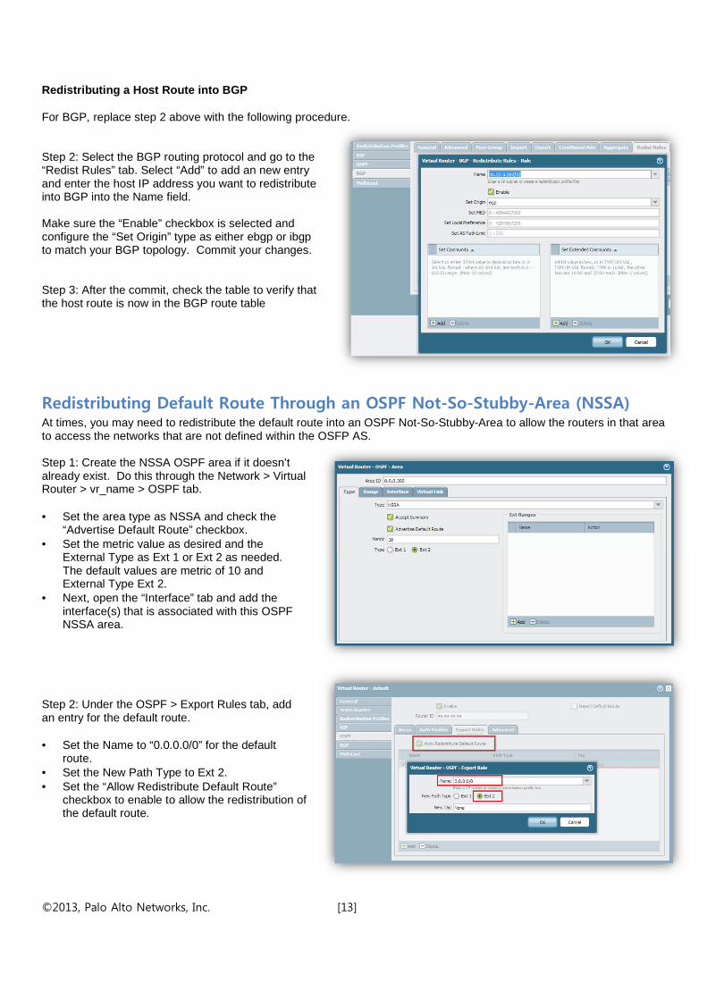
Redistributing a Host Route into BGP For BGP, replace step 2 above with the following procedure. Step 2: Select the BGP routing protocol and go to the “Redist Rules” tab. Select “Add” to add an new entry and enter the host IP address you want to redistribute into BGP into the Name field. Make sure the “Enable” checkbox is selected and configure the “Set Origin” type as either ebgp or ibgp to match your BGP topology. Commit your changes. Step 3: After the commit, check the table to verify that the host route is now in the BGP route table
Redistributing Default Route Through an OSPF Not-So-Stubby-Area (NSSA) At times, you may need to redistribute the default route into an OSPF Not-So-Stubby-Area to allow the routers in that area to access the networks that are not defined within the OSFP AS. Step 1: Create the NSSA OSPF area if it doesn’t already exist. Do this through the Network > Virtual Router > vr_name > OSPF tab. • Set the area type as NSSA and check the
“Advertise Default Route” checkbox. • Set the metric value as desired and the
External Type as Ext 1 or Ext 2 as needed. The default values are metric of 10 and External Type Ext 2.
• Next, open the “Interface” tab and add the interface(s) that is associated with this OSPF NSSA area.
Step 2: Under the OSPF > Export Rules tab, add an entry for the default route. • Set the Name to “0.0.0.0/0” for the default
route. • Set the New Path Type to Ext 2. • Set the “Allow Redistribute Default Route”
checkbox to enable to allow the redistribution of the default route.

©2013, Palo Alto Networks, Inc. [14]
Step 3: After the commit, check your route table to verify that the default route is now in the OSPF route table. Notice the new OSPF “Type O2” route for the newly injected default route on the illustration to the right. The metric is set to 255. Note: Another way to introduce a default route into a dynamic routing protocol like OSPF is with the Static Route Redistribution method shown in the earlier use case. Simply replace the static route in that example with the default route.
Redistributing RIP Routes into OSPF Environments that have multiple dynamic routing protocols deployed will have routing prefixes for each routing protocol and these will operate independently of each other. In order to inform each AS of routes in the other AS, redistribution profiles are needed to inject the routes from one to the other. Routers that are configured with more than one routing protocol are referred to as autonomous system boundary routers (ASBR) and these routers will have one or more interfaces defined with each routing protocol. ASBRs are used to perform the route redistribution between the two protocols. In this example, the firewall acts as the ASBR and has one interface configured with RIPv2 and another configured with OSPF. To allow each AS to access network prefixes defined on the other, redistribution profiles are created to inject the routes from the RIP AS to the OSPF AS and vice versa. Note: Care must be taken to ensure that identical route prefixes are not duplicated and redistributed as part of the redistribution profile. Step 1: Create a new Redistribution Profile to inject the RIP routes into the OSPF AS. Access the Network > Virtual Routers > vr_name > Redistribution Profiles > Add feature to create a new redistribution profile. • Select “rip” as the type and select the “Redist”
radio button to instruct the policy to redistribute the RIP routes.
• Set the priority for the policy. Lower priority numbers are executed first.
• Set the metric value for the redistributed route. Step 2: Instruct OSPF to “export” the redistribution profile containing the RIP routes. Access the Network > Virtual Routers > vr_name > OSPF > Export Rules feature to select the redistribution profile to export. Select the redistribution profile created in the previous step and select the New Path Type. In OSPF, external routes brought into the autonomous system can be one of two types: External Type 1 or External Type 2.
©2013, Palo Alto Networks, Inc. [15]
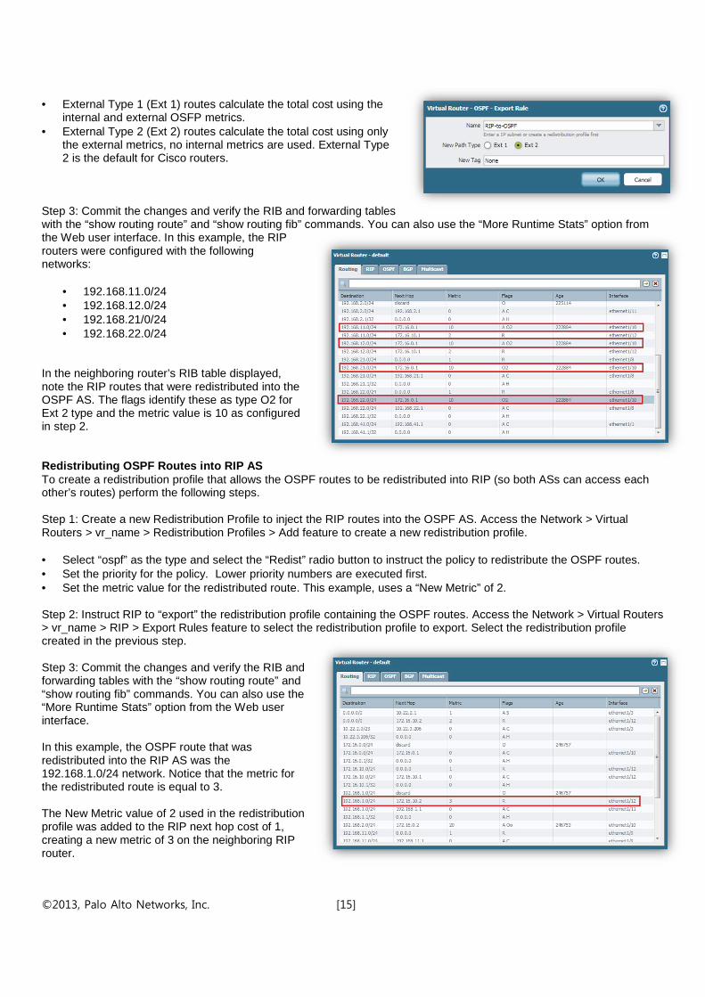
• External Type 1 (Ext 1) routes calculate the total cost using the
internal and external OSFP metrics. • External Type 2 (Ext 2) routes calculate the total cost using only
the external metrics, no internal metrics are used. External Type 2 is the default for Cisco routers.
Step 3: Commit the changes and verify the RIB and forwarding tables with the “show routing route” and “show routing fib” commands. You can also use the “More Runtime Stats” option from the Web user interface. In this example, the RIP routers were configured with the following networks:
• 192.168.11.0/24 • 192.168.12.0/24 • 192.168.21/0/24 • 192.168.22.0/24
In the neighboring router’s RIB table displayed, note the RIP routes that were redistributed into the OSPF AS. The flags identify these as type O2 for Ext 2 type and the metric value is 10 as configured in step 2. Redistributing OSPF Routes into RIP AS To create a redistribution profile that allows the OSPF routes to be redistributed into RIP (so both ASs can access each other’s routes) perform the following steps. Step 1: Create a new Redistribution Profile to inject the RIP routes into the OSPF AS. Access the Network > Virtual Routers > vr_name > Redistribution Profiles > Add feature to create a new redistribution profile. • Select “ospf” as the type and select the “Redist” radio button to instruct the policy to redistribute the OSPF routes. • Set the priority for the policy. Lower priority numbers are executed first. • Set the metric value for the redistributed route. This example, uses a “New Metric” of 2. Step 2: Instruct RIP to “export” the redistribution profile containing the OSPF routes. Access the Network > Virtual Routers > vr_name > RIP > Export Rules feature to select the redistribution profile to export. Select the redistribution profile created in the previous step. Step 3: Commit the changes and verify the RIB and forwarding tables with the “show routing route” and “show routing fib” commands. You can also use the “More Runtime Stats” option from the Web user interface. In this example, the OSPF route that was redistributed into the RIP AS was the 192.168.1.0/24 network. Notice that the metric for the redistributed route is equal to 3. The New Metric value of 2 used in the redistribution profile was added to the RIP next hop cost of 1, creating a new metric of 3 on the neighboring RIP router.

©2013, Palo Alto Networks, Inc. [16]
Redistributing Summarized Routes to BGP With the ever growing size of the Internet routing table, it is a good practice to aggregate more specific (longer) routing prefixes into summarized (shorter) prefixes before redistributing them into BGP route tables. This helps to keep the number of routes lower and improves route lookup and advertisement performance. For example, if the following longer (more specific) routes were defined within the OSPF AS, they can be aggregated to a shorter prefix as shown below. Longer specific network prefixes assigned:
• 192.168.1.0/27 • 192.168.1.32/27 • 192.168.1.64/27 • 192.168.1.96/27 • 192.168.1.128/27 • 192.168.1.160/27 • 192.168.1.192/27 • 192.168.1.224/27
These longer prefixes can be aggregated into one summary prefix of 192.168.1.0/24. Step 1. Configure a new redistribution profile with the “Destination” as the routes that need to be summarized. In this example, we will summarize all of the specific “/27” routes shown above from a connected interface that has them defined on the firewall. Select the “Redist” button. The metric value of “1” is used in this example. Step 2. In the BGP > Aggregate > Add configuration tab, configure the Aggregate Prefix and enable the “Summary” option checkbox. This will be used as the summary prefix for the longer destination routes that were configured in the Redistribution Profile in the previous step and will be advertised to the BGP neighbor.

©2013, Palo Alto Networks, Inc. [17]
Step 3. Configure the BGP > Redist Rules > Add tab with the redistribution profile. Use the drop down box to select the Redistribution Profile from the previous step. Select the “Enable” checkbox. Step 4. Commit the changes and verify the BGP Local RIB table to ensure that the routes from the redistribution profile are available. Use the More Runtime Stats > BGP > Local RIB function to view the firewall’s BGP route table. The longer “192.168.1.0” routes should be displayed. Notice that the Peer is set to “Local” and the Origin is “N/A” as the Redistribution Rule’s Set Origin parameter was set to “incomplete”. Use the More Runtime Stats > BGP > RIB Out function to view the Aggregated Route that is available to for advertising to the firewall’s BGP peers. Notice that the prefix is the summarized /24 route and the Aggregate Status is set to “aggregate”. Step 5: The neighboring BGP peer router should only be receiving the aggregated route prefix from the firewall that summarized the routes. In our lab example, we will look at the BGP peer firewall’s BGP Local RIB table to validate the single aggregated route advertisement.

©2013, Palo Alto Networks, Inc. [18]
Redistributing Static Routes to Select BGP Peers With BGP networks, there is often more than one peer to route traffic between (such as between two separate ISPs). In these cases, it can be useful to redistribute static or connected routes from the firewall to one of the peers, but not the other. This example shows how to configure the Palo Alto Networks firewall to redistribute a static route to just one of the BGP peers. There are two BGP peers defined on the firewall – one for ISPA and one for ISPB.
Step 1: Create a Redistribution Profile with the static or connected route prefix to redistribute into BGP. This example redistributes a static route into BGP and names the redistribution profile “Static-2-BGP”. Step 2: Configure BGP to redistribute the static route created in the previous step. • Select the redistribution profile in the Network >
Virtual Routers > vr_name > BGP > Redist Rule screen.
• Set the origin to the desired type and ensure that the “Enable” checkbox is selected.
Step 3: Commit the changes and verify the BGP peer information and the advertised routes with the “show routing protocol bgp rib-out” command. The static route should be in the RIB Out table.

©2013, Palo Alto Networks, Inc. [19]
Step 4: Using the Network >Virtual Routers > vr_name > BGP > Export tab, create a new export rule to filter a BGP peer.
• In the General tab, select Add and choose the BGP peer to advertise or block the route to. In this example, we will choose AS65400 and “Deny” the static route.
• In the Match tab under the Address Prefix, add the route prefix to export. In this example, we will export the static route that was added earlier – 10.22.2.0/24.
• In the Action tab, select the “Deny” action.
Step 5: Commit the changes made and review the BGP RIB Out information with the “show routing protocol bgp rib-out” command to validate that the route is only being advertised to the desired BGP peer.
Redistributing Routes Between BGP and OSPF One of the more popular route redistribution scenarios when running BGP at the edge of the network is to redistribute specific routing prefixes into OSPF to allow OSPF to reach specific external networks. When redistributing routes from BGP to OSPF, the firewall must act as an Autonomous System Boundary Router (ASBR) with both BGP and OSPF configured. When importing route prefixes from an Internet BGP peer into the firewall’s BGP route table, the firewall’s maximum route table capacity must be taken into consideration. Route aggregation must be used to reduce the number of routes brought into the firewall’s BGP AS. Note: Each Palo Alto Networks firewall has a specific maximum route table and forwarding table capacity. Please refer to your firewall’s documentation for the maximum capacity so you can plan for the number of routes that can be imported from your BGP peer. There are several different ways to populate route prefixes into BGP and OSPF for the purpose of redistribution. This series of examples will show how to configure a few of these use cases. For example:
• Static or connected routes can be imported or redistributed into the AS for redistribution to each other. • BGP route prefixes can be summarized from the Internet BGP peer and imported for redistribution to OSPF. • A default route from the Internet BGP peer can be redistributed from BGP to OSPF.
In this extended use case, several examples are shown in sequence to illustrate how external routes can be redistributed into BGP, exported to a BGP peer, filtered between BGP peers, and redistributed between BGP and an OSPF autonomous system.

©2013, Palo Alto Networks, Inc. [20]
Network Topology for Use Case Examples
The lab network topology used in the examples shown in the following use cases was created with three Palo Alto Network firewalls. Although Router A and Router C were constructed with firewalls, these can be traditional routers. Router A: Setup as the BGP Internet Peer and only runs the BGP protocol. It advertises its route prefixes to Router B. Router B: Setup as the enterprise firewall and runs BGP and OSPF. It is the Autonomous System Boundary Router. Router C: Setup as an internal OSPF router that is part of the enterprise’s private network. It only runs OSPF. In order to populate the BGP and OSPF route tables with routes for the use case examples, the following network prefixes were redistributed into each dynamic routing protocol:
• Router A’s connected routes were redistributed into the BGP route table. These routes act as the public internet routes that are advertised from the service provider to each of its customers. The connected routes included:
o 10.30.40.0/22 o 192.168.111.0/24 o 192.168.122.0/24 o 192.168.133.0/24 o 192.168.144.0/24
• A single connected route from Router C was redistributed into the OSPF route table. This route acts as the enterprise’s AS route that needs to be advertised out to the BGP AS.
o 192.168.211.0/24 • Router B acts as the ASBR that runs both routing protocols and will be used to perform the route redistribution
between the two routing protocols.
Redistributing Connected Routes Into BGP for Redistribution to OSPF This example shows the use case that is needed to populate Router A’s BGP route table with the firewall’s connected routes. The example also shows how the BGP filters can be used to specify which routes are advertised to its peers and can serve as a guide on how to filter BGP routes imported and exported from the firewall’s BGP route table. Step 1: Create a redistribution profile on Router A to inject the firewall’s connected routes into BGP. Priority of 1 is used with a New Metric value of 1 and the “Redist” button is selected to allow the redistribution.
©2013, Palo Alto Networks, Inc. [21]
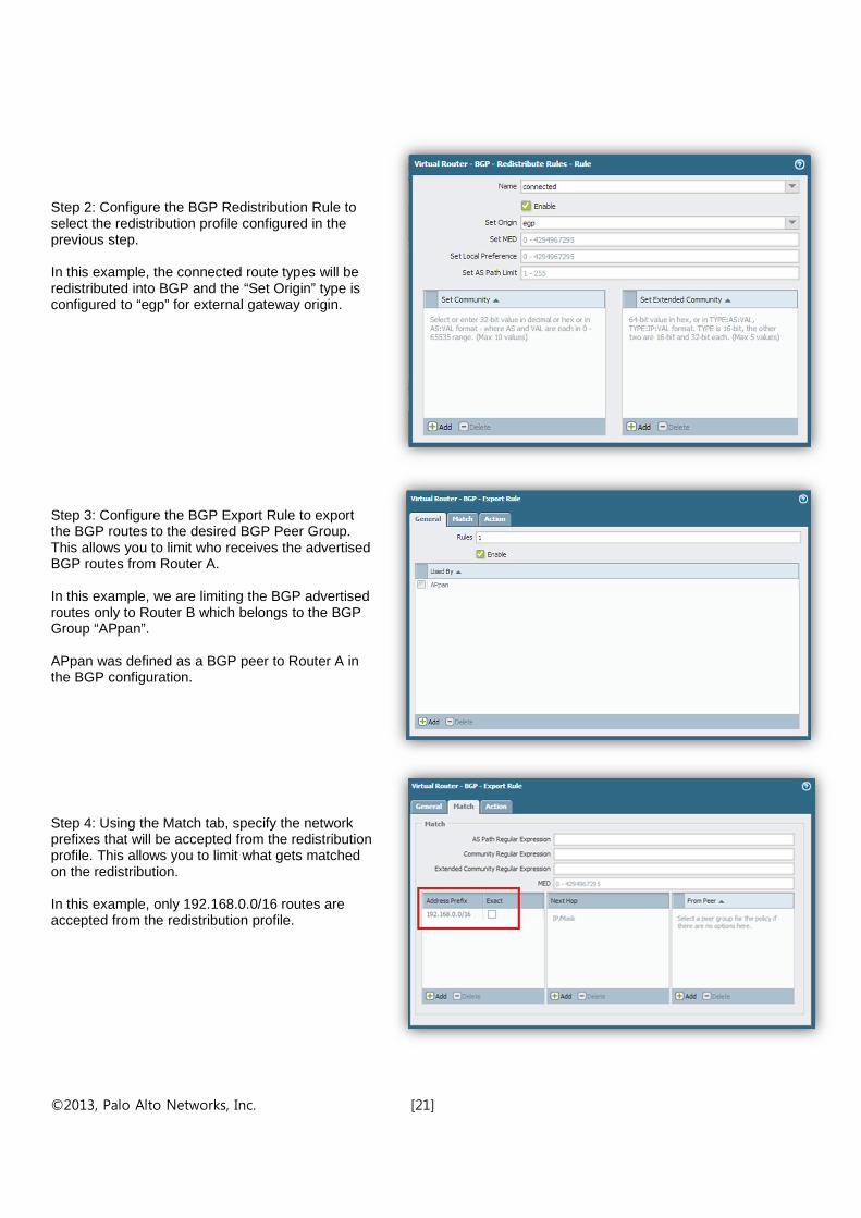
Step 2: Configure the BGP Redistribution Rule to select the redistribution profile configured in the previous step. In this example, the connected route types will be redistributed into BGP and the “Set Origin” type is configured to “egp” for external gateway origin. Step 3: Configure the BGP Export Rule to export the BGP routes to the desired BGP Peer Group. This allows you to limit who receives the advertised BGP routes from Router A. In this example, we are limiting the BGP advertised routes only to Router B which belongs to the BGP Group “APpan”. APpan was defined as a BGP peer to Router A in the BGP configuration. Step 4: Using the Match tab, specify the network prefixes that will be accepted from the redistribution profile. This allows you to limit what gets matched on the redistribution. In this example, only 192.168.0.0/16 routes are accepted from the redistribution profile.
©2013, Palo Alto Networks, Inc. [22]
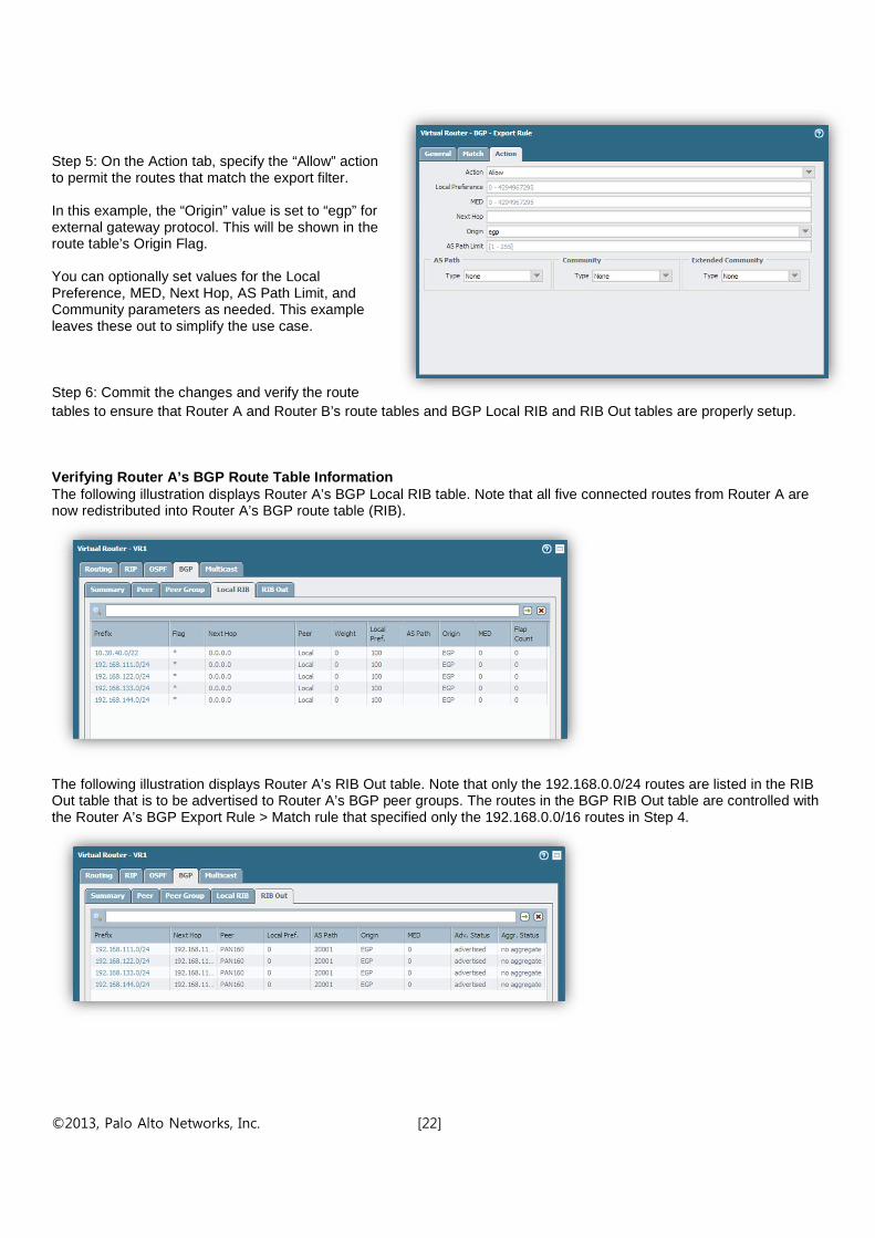
Step 5: On the Action tab, specify the “Allow” action to permit the routes that match the export filter. In this example, the “Origin” value is set to “egp” for external gateway protocol. This will be shown in the route table’s Origin Flag. You can optionally set values for the Local Preference, MED, Next Hop, AS Path Limit, and Community parameters as needed. This example leaves these out to simplify the use case.
Step 6: Commit the changes and verify the route tables to ensure that Router A and Router B’s route tables and BGP Local RIB and RIB Out tables are properly setup.
Verifying Router A’s BGP Route Table Information The following illustration displays Router A’s BGP Local RIB table. Note that all five connected routes from Router A are now redistributed into Router A’s BGP route table (RIB).
The following illustration displays Router A’s RIB Out table. Note that only the 192.168.0.0/24 routes are listed in the RIB Out table that is to be advertised to Router A’s BGP peer groups. The routes in the BGP RIB Out table are controlled with the Router A’s BGP Export Rule > Match rule that specified only the 192.168.0.0/16 routes in Step 4.
©2013, Palo Alto Networks, Inc. [23]
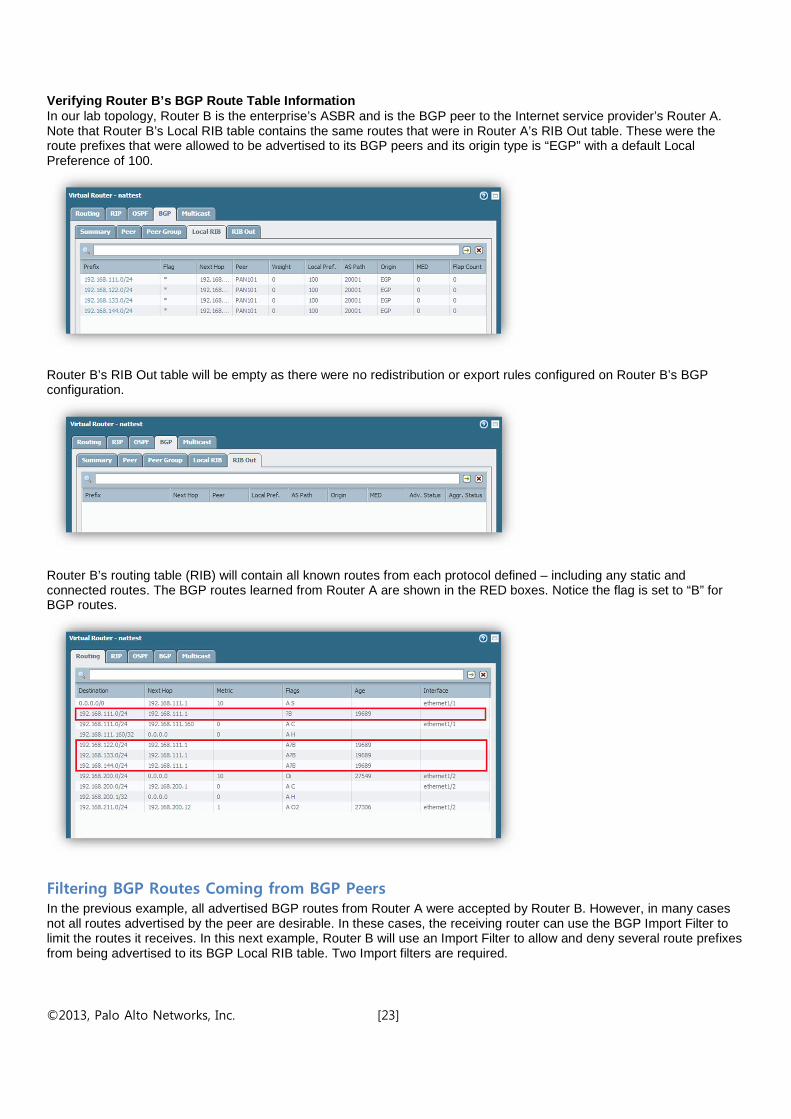
Verifying Router B’s BGP Route Table Information In our lab topology, Router B is the enterprise’s ASBR and is the BGP peer to the Internet service provider’s Router A. Note that Router B’s Local RIB table contains the same routes that were in Router A’s RIB Out table. These were the route prefixes that were allowed to be advertised to its BGP peers and its origin type is “EGP” with a default Local Preference of 100.
Router B’s RIB Out table will be empty as there were no redistribution or export rules configured on Router B’s BGP configuration.
Router B’s routing table (RIB) will contain all known routes from each protocol defined – including any static and connected routes. The BGP routes learned from Router A are shown in the RED boxes. Notice the flag is set to “B” for BGP routes.
Filtering BGP Routes Coming from BGP Peers In the previous example, all advertised BGP routes from Router A were accepted by Router B. However, in many cases not all routes advertised by the peer are desirable. In these cases, the receiving router can use the BGP Import Filter to limit the routes it receives. In this next example, Router B will use an Import Filter to allow and deny several route prefixes from being advertised to its BGP Local RIB table. Two Import filters are required.

©2013, Palo Alto Networks, Inc. [24]
Step 1: On Router B’s Network > Virtual Routers > vr_name screen, select the BGP tab to configure an Import Filter. • Select the Import tab and click Add to create a new
filter. The first filter in this example will “block” several route prefixes advertised from Router A.
• Give the new filter rule a name. This example names the filter “Deny-Specific”.
• Select the BGP peer that this filter will apply to. This example chooses the “ACCESSPA101” BGP peer group that Router A belongs.
• Enable the rule with the checkbox. Step 2: In the Match tab, enter the matching criteria for the filter. This example will match on two specific route prefixes as shown in the illustration. • 192.168.111.0/24 • 192.168.122/0/24 Step 3: In the Action tab, select the desired action. This example uses the “Deny” action to block the route prefixes specified in the Match tab’s criteria. Step 4: Create a second Import filter to “allow” the desired routes from Router A. • Select the Import tab and click “Add” to create a
new filter. The second filter in this example will permit an aggregated route prefix for 192.168.0.0/16 from Router A.
• Give the new filter rule a name. This example names the filter “Accept-All”.
• Select the BGP peer that this filter will apply to. This example chooses the “ACCESSPA101” BGP peer group that Router A belongs to.
• Enable the rule with the checkbox.

©2013, Palo Alto Networks, Inc. [25]
Step 5: In the Match tab, enter the matching criteria for the filter. This example will match on an aggregated route prefix as shown in the illustration. • 192.168.0.0/16
Step 6: In the Action tab, select the desired action. This example uses the “Allow” action to accept the route prefix specified in the Match tab’s criteria. By combining the two Import rules, Router B is now able to filter out the undesired route prefixes from Router A. Note: The order of the Import rules is critical for proper execution. The more specific “deny” rule should be placed ahead of the more general “allow” rule. Step 7: Commit the change and verify Router B’s BGP Local RIB table to validate that only the desired routes are imported and the undesired routes are denied. In this example, we can see from the illustration below that the two specific “denied” prefixes have been removed as directed from the “Deny-Specific” setting.
Redistributing Routes From BGP to OSPF This example shows how to create the necessary redistribution profile and OSPF export configuration to redistribute route prefixes from the BGP AS to the OSPF AS. This example assumes that the necessary route prefix aggregation was performed when the BGP routes were imported from the Internet BGP peer and will simply redistribute all BGP route prefixes.

©2013, Palo Alto Networks, Inc. [26]
Step 1: On the firewall acting as the ASBR, create a redistribution profile to define the BGP redistribution route type. This example names the redistribution profile “BGP-2-OSPF”. • Select the “bgp” checkbox from the redistribution
type on the General Filter tab. • Select the “Redist” radio button to allow
redistribution of BGP routes. • Set the profile’s Priority. Lower priority profiles
have a higher priority. • Set the New Metric value. Lower metric values are
selected as higher priority routes for the FIB table. • Save the redistribution profile. Step 2: From the Network > Virtual Routers > vr_name screen, select the target protocol to redistribute the BGP routes into. • In this example, “OSPF” is selected because we
are redistributing from BGP to OSPF. • On the OSPF Export Rules tab, create a new
export rule and select the BGP redistribution profile created in the previous step.
• Select the desired New Path Type. By default, OSPF external type 2 is selected and this will only take the external metric into consideration.
Step 3: Commit your changes and validate the route tables on the firewall and each of the neighboring routers to validate that the BGP routes are now redistributed into OSPF. The following illustration shows Router C’s route table (RIB). The connected routes from BGP are shown in the OSPF route table with the flags “O2” for OSPF Ext 2 type.
Redistributing Routes from OSPF to BGP This example shows the reverse of the previous use case and takes routes from the OSPF route table and redistributes them into the BGP AS. It will redistribute a set of “connected” routes from OSPF into the BGP AS. Note: Care must be taken when redistributing routes from a link-state dynamic routing protocol such as OSPF into a distance-path vector protocol such as BGP. If there are frequent link state changes in the OSPF environment and these networks are advertised into BGP, it can cause a great deal of convergence activity on the BGP side. In many cases, it’s best to advertise static routes or well-designed summarized route prefixes from OSPF to BGP. This limits the possibility of unnecessary convergence when links change dynamically in the OSPF AS.
©2013, Palo Alto Networks, Inc. [27]
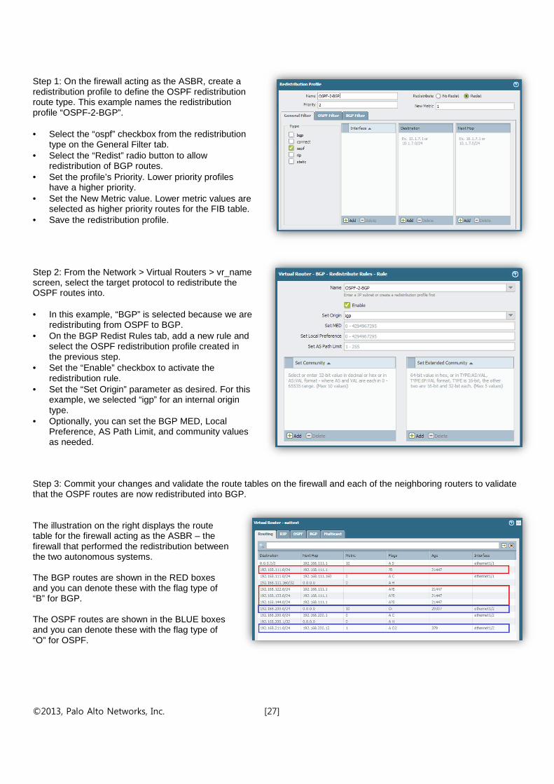
Step 1: On the firewall acting as the ASBR, create a redistribution profile to define the OSPF redistribution route type. This example names the redistribution profile “OSPF-2-BGP”. • Select the “ospf” checkbox from the redistribution
type on the General Filter tab. • Select the “Redist” radio button to allow
redistribution of BGP routes. • Set the profile’s Priority. Lower priority profiles
have a higher priority. • Set the New Metric value. Lower metric values are
selected as higher priority routes for the FIB table. • Save the redistribution profile. Step 2: From the Network > Virtual Routers > vr_name screen, select the target protocol to redistribute the OSPF routes into. • In this example, “BGP” is selected because we are
redistributing from OSPF to BGP. • On the BGP Redist Rules tab, add a new rule and
select the OSPF redistribution profile created in the previous step.
• Set the “Enable” checkbox to activate the redistribution rule.
• Set the “Set Origin” parameter as desired. For this example, we selected “igp” for an internal origin type.
• Optionally, you can set the BGP MED, Local Preference, AS Path Limit, and community values as needed.
Step 3: Commit your changes and validate the route tables on the firewall and each of the neighboring routers to validate that the OSPF routes are now redistributed into BGP. The illustration on the right displays the route table for the firewall acting as the ASBR – the firewall that performed the redistribution between the two autonomous systems. The BGP routes are shown in the RED boxes and you can denote these with the flag type of “B” for BGP. The OSPF routes are shown in the BLUE boxes and you can denote these with the flag type of “O” for OSPF.

©2013, Palo Alto Networks, Inc. [28]
The ASBR firewall’s BGP Local RIB table displays both the redistributed BGP routes (in RED) and OSPF routes (in BLUE). Notice the Origin label and the AS Path. From these two fields, you can tell the source of these routing prefixes. The ASBR firewall’s BGP RIB Out table displays the two OSPF routes that were redistributed from the OSPF AS. The BGP RIB Out table will display the routes to be sent to its BGP Peer. On the southbound router from the ASBR firewall, you should see the BGP routes that were redistributed into the OSPF AS. The redistributed BGP routes are identified by the flag type “O 2” for OSPF Ext 2 type. Because our examples used a Metric = 1 in the redistribution profiles, you can easily spot which routes were passed into OSPF from BGP. Note: The 192.168.200.0/24 route prefix with a metric = 10 and a flag type of “O I” was the locally connected route that was redistributed into the OSPF AS to populate the OSPF route table in our use case.
Summary As this tech note shows, there are many different use cases and possible scenarios for route redistribution which depend on the network topology, routing protocols used, and the needs of the network. This paper shows some of the more popular and basic redistribution requirements in enterprise networks. Using the examples shown in the tech note, customers can configure the necessary redistribution profiles and protocol import export rules to meet their needs.