understanding of foundations: success of a civil … · understanding of foundations: success of a...
TRANSCRIPT

1
Understanding of Foundations:
Success of a Civil Engineer….!
Part B: Heavy Foundations
• Theory: Behaviour of Pile Foundations
• Design of Pile Foundations
• Case Study 1 : Heavy Foundations for Power Plant
• Case Study 2 : Deep Excavation Pit

2
Behavior of Pile Foundations
Pile Foundations – Load Transfer Mechanism
Initially Pile-Soil system behaves elastically
Mob. of Friction: 0.3% to 1% of dia.

3
Pile Foundations – Load Transfer Mechanism
Mob. of Friction: 0.3% to 1% of dia.
Pile Foundations – Failure Mechanism

4
P M
V
Pile cap
Batter pile
Vertical pile
Axially Loaded Piles
P P M
V
Axially Loaded Piles – Load Transfer
W

5
M
z
Deflection
y
Slope
S
Moment
M
Shear
V
Soil Reaction
p
Forces and Deflections of Long Piles
Method of estimation of Pile Capacity
By the use of static bearing capacity equations
By the use of the values of SPT and CPT
By field load tests
By dynamic method

6
Ultimate Pile Capacity (IS 2911)
Ultimate Capacity of Pile , Qult = QEB + QSKIN – Wp
QEB = Ultimate End Bearing
QEB = c* Nc + Pd * Nq * Ap
QSKIN = Ultimate Skin Friction
QSKIN = *c + K*P*tan x As
Wp = Self weight of Pile
Qsafe = Qult / FoS
Qult
QEB
QSKIN
Ultimate Capacity of Piles - Self Weight
Ultimate Capacity of Pile , Qult = QEB + QSKIN – Wp
Ultimate End Bearing, QEB = 300 T FoS = 2.5
Ultimate Skin Friction, QSKIN = 100 T
Self Weight of Pile, W = 20 T
Case 1: Qsafe = Qult / FoS = 160 T (EPC Contractors)
Case 2: Qsafe = (Qult – W) / FoS = 152 T (Reasonable)
Case 3: Qsafe = Qult / FoS – W = 140 T (Consultants)
(too conservative, consultants may prefer…….or Contractors of item rate
contracts)

7
Pile Foundations – Uplift Capacity of Pile
Quplift
QSKIN
W
Uplift Capacity of Piles
Ultimate Skin Resistance,
QSKIN = *c + K*Pdi*tan x As + Wp
For Cohesive Soils:
The skin resistance in both compression and uplift cases
are same
For Cohesionless Soils
A reduction of 50% to 33% is generally adopted (industry practice)
Ultimate Uplift Capacity = 1/2 to 2/3 of Ultimate Skin
Resistance.

8
Negative Drag on Piles
Factor of Safety = Ult. Skin Resistance of Single Pile
Working load + (-) ve skin friction
Part B: Heavy Foundations
• Behaviour of Pile Foundations
• Case Study 1 : Heavy Foundations for Power Plant
• Case Study 2 : Deep Excavation Pit

9
Artistic View of Thermal Power Plant
2 X 660 MW (Phase 1)
Soil Profile & Operational Challenges
-70
-60
-50
-40
-30
-20
-10
0
0 10 20 30 40 50 60 70 80 90 100
Ele
va
tio
n [
m]
Standard Penetration Test, SPT N [ ]
GWT
40m
60m

10
Casing
Drilling fluid enables for the application of
hydrostatic pressure against the sides of
the pile by creating a bridging effect :
If top level of Drilling Fluid drop below ground
water table, the pile hole will collapse.
When Pile Bore Collapse happen.....?
Water Table
Casing
Stable Pile Bore Un-stable Pile Bore
Water Table
Operational Excellence with “Best Practices”

11
Quality – Borehole Stability
Top Vibro Hammer to install 10m deep Temporary Casing
Quality – Bentonite Recycling
De-sanders to ensure quality of recycled Bentonite for borehole stability

12
Pile Integrity Tests for all Installed Piles to ensure Quality of Piles
Quality – Testing (PIT)
Load Test Setup for 1200MT
Quality – Testing (PLT)

13
Productivity – Timely Concreting
Timely Concreting (Dedicated Batching Plant ~ 1,00,000m3 batched on site)
Productivity – Supporting Equipment
Dedicated Equipment to ensure optimal cycle times of piling process

14
Note: Above piles installed to 40m depth using 3 rigs (avg. productivity ~ 50 nos x 40m / 3 rigs / 6 days ~ 111 lin.m. / rig / day)
30
50
70
90
110
130
150
170
Au
g-1
1
Au
g-1
1
Sep
-11
Oct
-11
No
v-1
1
Dec
-11
Jan
-12
Feb
-12
Mar
-12
Ap
r-1
2
May
-12
Jun
-12
Jul-
12
Jul-
12
Rat
e o
f P
rod
uct
ion
(Li
n.m
/Rig
/Day
)
Week
Weekly Rate of Production
Productivity
Part B: Heavy Foundations
• Behaviour of Pile Foundations
• Case Study 1 : Heavy Foundations for Power Plant
• Case Study 2 : Deep Excavation Pit

15
Past Experience
BBCL – Breeze Residences, Chennai
30
About the project
• Project : 3B+G+18 storeyed Residential Project
• “Breeze Residences”, Kilpauk, Chennai
• Developer : M/s BBCL Developers Pvt Limited.
• Client Consultant : M/s. Buro Engineers Ltd.
• Specialised Foundation: M/s. Keller Ground Engineering India Pvt. Ltd.
Contractor
• Keller scope : Design & Build contract - BCIS Pile foundation &
Permanent Retention System

16
31
Project Location
32 32 32
Plan Layout

17
33 33 33
Geotechnical Challenges
• Loose/weak layers at top (N~5) - Low in-situ bearing pressure
• Hard strata at deeper depths - Foundation piles to be designed as
end bearing & shall rest on rocky strata
• Deeper Excavation(-10.2m) - Overall stability is a concern
• Sandy soils (Fines~5% to 25%) - Exerts high Lateral pressure on wall
& Shallow GWT(-5.0m from EGL)
• Continuous Dewatering reqd. - Chances of seeping of soil particles
• High lateral wall deflection - Ground subsidence
• Settlements & Tilting of adjacent buildings
34 34 34
Scope of Work - Foundation Piles
Foundation Package
Design & Build Depth Optimization
BCIS Piles 900, 750 & 600mm Piles (186 Nos.)
Pile Load Tests Routine Tests (3 Nos.-1 for each dia.)
PIT 107 Nos

18
35 35 35
Scope of Work – Retention System
Retention Package
Design & Build Contiguous Bored Pile with Inclined Anchors
BCIS Piles
Retention (145 Piles)
Retention Cum Foundation (57 Piles)
Grouting Cement : Bentonite (201 Nos.)
Anchors 1st level – 103 Nos
Capping Beam Length – 172m
36 36 36
Design of Foundation Piles
Confirming Design by M/s BBCL (Client)
Proposed by M/s Keller (Depth Optimization)
SI. No. Pile dia.
(mm)
Length of pile
(m)
Vertical Pile capacity
(MT)
1 600 15 150
2 750 15 230
3 900 15 300
SI. No. Pile dia (mm) Length of pile
(m)
Vertical Pile capacity
(MT)
1 600 12.5 175
2 750 13.0 260
3 900 13.0 332

19
37 37 37
Layout Plan – Foundation Piles & Retention System
38 38 38
Preliminary Analysis – GGU Retain

20
39 39 39
Proof Checking – Plaxis 2D
40 40 40
Summary of Results

21
41 41 41
Typical Cross Section
42 42 42
Execution – Installation of Piles
Casing installation
Boring in
progress
Flushing
Concreting

22
43 43 43
Execution – Vertical Grout Columns
Inclination checking Boring in progress Grout mixer set-up
Primary Grouting Secondary Grouting
44 44 44
Execution – Ground Anchors
Inclination checking Anchor Fabrication
Anchor Installation Anchor Strand Spacer Grout Pipes

23
45 45 45
Execution – Capping Beam
Levelling & Preparation Laying of PCC
Reinforcement fabrication Completed Capping Beam
46 46 46
Deflection Monitoring Points
Deflection monitoring points

24
47 47 47
Deflection Monitoring Results
Maximum Predicted Deflection = 39 mm
(Plaxis Analysis)
Recorded settlement = 9mm
48 48 48
Completed Picture

25
Completed Excavation
Completed Excavation

26
Present site condition
Basements completed

27
Latest Photograph
Past Experience
VGN – Notting Hill, Nungambakkam, Chennai

28
55
About the project
• Project : Residential Building (3B+G+16 Floors)
• Developer : M/s VGN Developers Pvt. Ltd.
• Total Basement Area : 2175.7 sq.m
• Site dimensions : 60mx36m
• Excavated Perimeter : 218m (approx.)
• No. of Basements : 3 Nos.
• Depth of excavation : 8.5m from present ground level (RL -3.0m)
• Working level : 3.0m below NGL (RL 0.0m)
• Retention system : Contiguous Bored Pile wall with 1 level anchor
• Structure : Multi-storeyed (G+16) Residential buildings with 3 basements
56
Project Location

29
57 57 57
Plan Layout
Ad
jacen
t B
uild
ing
(G+
5)
(W
est
sid
e)
Adjacent Building (G+7) (South
side)
58 58 58
Subsoil Condition
Typical Soil Profile
0.0
14.0
17.0
Dense Silty
Sand+Gravel
N>50, φ= 36°
Weathered Rock
N>100,
Cu=400kPa
2.0
MD Silty Sand
N~17, φ= 30°
Clayey Sand /
Sandy Clay
N~8, Cu=40kPa
Filled up
N~7, φ= 28°
10.0
20.0
6.0
MD to Dense
Silty Sand
N~30, φ= 34°

30
59 59 59
Geotechnical Challenges
Following are the challenges related to RETENTION SYSTEM FOR
DEEP EXCAVATION may need to be addressed:
• Deep Excavation (depth ~ 11.5m) adjacent to tall structures (G+7)
• Overall Stability of the excavation system
• Nature of in-situ soil – Granular content (70% to 90%) which exerts
high lateral pressure than cohesive soil
• Ground Water Level at Shallow Depth (3m below EGL)
• Settlement/ tilting of existing structures adjacent to the excavation
• Ground Subsidence due to excessive dewatering (retention side)
• Lateral deflection of the Retention
60
• CB piles
• Number of piles - 271nos
• Diameter of piles - 750mm with 820mm c/c distance
• Length of retention piles - 16m from Present ground level
• Grout columns
• Number of Grout columns - 270 nos. with 12m depth from Present GL
• Diameter of grout columns - 150mm
Proposed retention system - CBP wall with inclined anchors
Pre excavation of about 3m were carried out at site to optimize the design of retention system
Total length of retention - 218m
Detail showing Retention piles with Grout columns
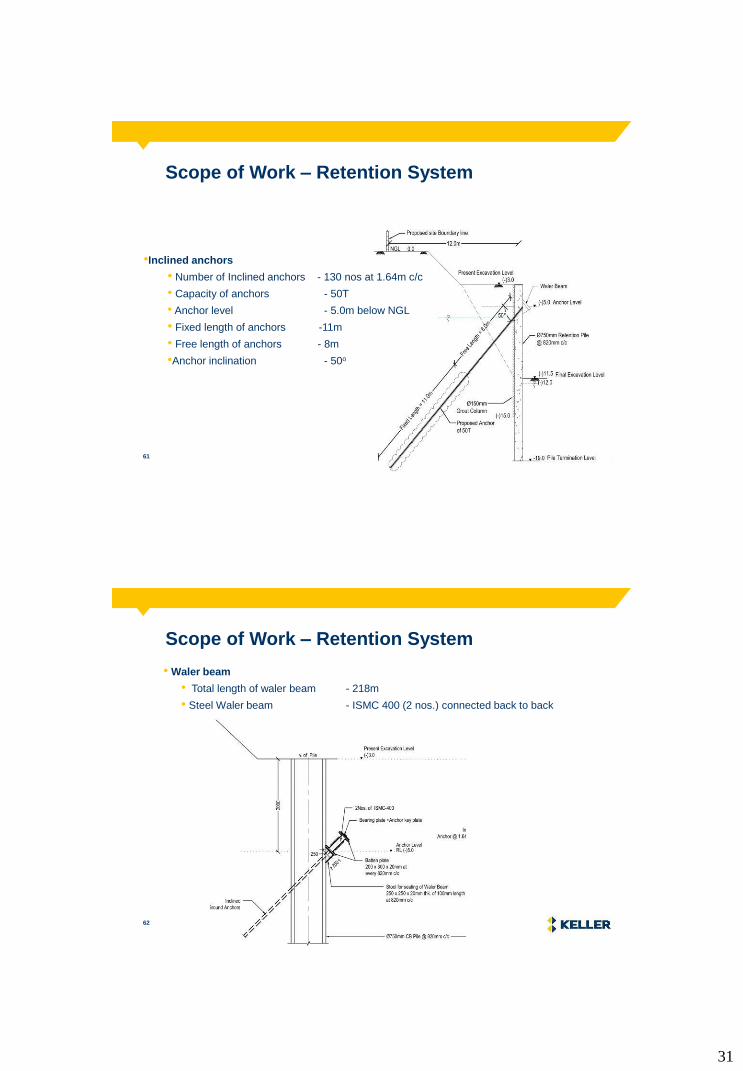
Scope of Work – Retention System
31
61
Scope of Work – Retention System
•Inclined anchors
• Number of Inclined anchors - 130 nos at 1.64m c/c
• Capacity of anchors - 50T
• Anchor level - 5.0m below NGL
• Fixed length of anchors -11m
• Free length of anchors - 8m
•Anchor inclination - 50o
Typical Cross section of Inclined Anchor
62
Scope of Work – Retention System
Typical Cross section of Inclined Anchor
• Waler beam
• Total length of waler beam - 218m
• Steel Waler beam - ISMC 400 (2 nos.) connected back to back

32
63
Retention System Layout – Initial Proposal
Typical Cross section of Inclined Anchor
64
Typical Cross section of Inclined Anchor
Retention System Layout – Existing Old
Foundation Piles

33
65
Realignment of Retention System
Typical Cross section of Inclined Anchor
66 66 66
Preliminary Analysis – GGU Retain

34
67 67 67
Proof Checking – Plaxis 2D
68 68 68
Summary of Results
GGU Analysis Plaxis Analysis
GWT at -6.0m GWT at -6.0m
Plie dia., m 0.75 0.75
Pile spacing, m 0.82 0.82
Pile length, m 16 16
Embedment, m 7.5 7.5
Surcharge, kPa 10 20
GWT @ Retention side, m -6.0 -6.0
Max BM, kN.m/m Wall 409.3 484
Max SF, kN/m Wall 248.39 214
Anchor Capacity, Tons 50 50
Deflection, mm 1 in 550 1 in 400
DescriptionGWT at -2.5m GWT at -2.5m
Pile dia., m 0.75 0.75
Pile spacing, m 0.85 0.85
Pile length, m 16 16
Embedment, m 8.6 8.6
Surcharge, kPa 10 20
GWT at retention side, m -2.5 -2.5
Max BM, kN.m / m wall 468 562
Max SF, kN / m wall 249 193
Anchor force, Ton / m wall 24 27
Anchor Capacity, Tons 41.0 46.0
Deflection, mm 1 in 500 (15mm) 1 in 250 (30mm)
No. of models (options) 20 to 25 6 to 8
DescriptionGGU Analysis Plaxis Analysis

35
69 69 69
Typical Cross Section
70 70 70
Deflection Monitoring Points

36
71 71 71
Deflection Monitoring Points
Maximum Predicted Deflection = 25 mm
(Plaxis Analysis)
Recorded settlement (till date) = 17 mm
-10
-9
-8
-7
-6
-5
-4
-3
-2
-1
0
1
2
3
4
5
6
7
8
9
10
11
0 5 10 15 20 25 30
Plaxis 3 4
5 6 7
8 9 10
11 12 13
14 15 16
17 18
72 72 72
Completed Picture

37
73 73
Introduction to Diaphragm Wall system
74 74
What is Diaphragm Wall?
A Diaphragm wall is a technique used to build
reinforced concrete walls in the area of soft earth
close to open water or with high ground water table
to stabilize deep excavations and as deep
foundation elements.

38
75 75
About Diaphragm Wall • Diaphragm walls are typically constructed by starting
with a set of guide walls, typically 1 meter deep and 0.5
meter thick.
• The guide walls are constructed on the ground surface
to outline the desired slurry trench(es) and guide
excavation.
• Excavation is done using a special clamshell-shaped
digger or a hydromill trench cutter. The excavator digs
down to design depth, or bedrock, for the first cut.
• The excavator is then lifted and moved along the trench
guide walls to continue the trench with successive cuts
as needed.
• The trench is kept filled with slurry (usually a mixture of
bentonite and water) at all times to prevent collapse.
76 76
About Diaphragm Wall • Once a particular length is reached, a reinforcing cage is
lowered into the slurry-filled pit and the pit is filled with concrete
from the bottom up using tremie pipes.
• The concrete displaces the bentonite slurry, which is pumped
out and recycled.
• Slurry walls are built to enclose the desired area, blocking water
and softened earth from flowing into it.
• On completion of concreting, digging within the now concrete
wall-enclosed area can proceed.
• To prevent the concrete wall from collapsing into the newly open
area, temporary supports such as tiebacks or anchors are
installed.
• When completed, the structure built within the walled-off area
supports the wall, so that tiebacks and/or other temporary
bracing may be removed.

39
77 77
Construction Procedure of Diaphragm Wall
Construction Procedure of D-wall
78 78
Construction Procedure of Diaphragm Wall (Typical)
Stage 1: Construction of Guide Walls
Stage 2: Preparation of the Supporting Slurry
Stage 3: Excavation of Diaphragm-wall
Stage 3a: Stop Ends Fixing
Stage 4: Lowering of Reinforcement Cage
Stage 5: Concreting & Stop Ends Removal

40
79 79
Project Background
80 80
Project Background
• Project : Commerzone IT Building (3B+G+9F)
• Location : Porur, Chennai
• Owner : M/s K Raheja Corp
• Total Plot Area : 25,800 Sq. M (approx.)
• Total Basement Area : 15,250 Sq. M (approx.)
• Excavated Perimeter : 650 m (approx.)
• No. of Basements : 3 Nos.
• Retention system : Diaphragm wall with Anchors
• Depth of excavation : 11.3m from Existing Ground Level (EGL)
• Scope of Work : Design & Execution of Diaphragm Wall.
• Area of D-Wall : 11, 700 Sq.M
• Depth of Retention : ~18m

41
81 81
Aerial View
82 82
Overall Layout Plan

42
83 83
SPT N value & Grain Size Distribution
84 84
Idealised Soil Profile
Soil Description Depth
from
(m)
Layer
thk. (m)
SPT N
Values
Clayey silt (MI) / Silty Clay (CI) 0.0 3.0 11
Clayey silt (MH) / Silty Clay (CH) 3.0 3.0 14
Clayey silt (MH) / Silty Clay (CH) 6.0 2.0 11
Clayey silt (MH) / Silty Clay (CH) 8.0 3.0 17
Clayey silt (MH) / Silty Clay (CH) 11.0 2.0 10
Clayey Silty Sand (SM) / (SC) 13.0 2.0 6
Clayey Silty Sand (SM) / (SC) 15.0 3.0 50
Weathered Rock 18.0 6.0 >100

43
85 85
Geo-Technical Problems
The geotechnical problems of the site are listed below,
• Proposed site comprises of top 15m compressible silty clay.
• High Ground water table (GWT at 2.5 m below EGL).
• Adjacent building with closer setback distances (say 9m).
• Deep excavation (11.3m below EGL).
• Overall stability of Retention system.
86 86
Design Considerations
Retention System Details:
• Length of Retention system : 650 m
• Existing Ground Level : 0.0 m
• Final Depth of Excavation : 11.3 m below EGL
• Design Water Table : 2.5 m below EGL
Possible solutions:
• Contiguous bored pile (CBP) wall with lateral support
• Diaphragm wall with lateral supports - SELECTED

44
87 87
Retention System used for analysis
-12.3 m GWT
88 88
Typical D-wall Cross Section

45
89 89
Wallap Analysis (Stretch-1)
90 90
Wallap Analysis Results (Stretch-1)

46
91 91
Wallap Analysis (Stretch-2)
92 92
Wallap Analysis Results (Stretch-2)

47
93 93
Plaxis Analysis (Stretch-1)
94 94
Plaxis Analysis Results (Stretch-1)

48
95 95
Plaxis Analysis Results Summary (Stretch-1)
96 96
Plaxis Analysis (Stretch-2)

49
97 97
Plaxis Analysis Results (Stretch-2)
98 98
Plaxis Analysis Results Summary (Stretch-2)

50
99
Project Information
• Project : Construction of Diaphragm wall for Underground Metro
Station, Hazratganj
• Location : Hazratganj, Lucknow
• Owner : Lucknow Metro Rail Corporation (LMRC)
• Main Con : M/s Gulermak - Tata Projects Limited JV
• Design consultants : Tandon Consultants – Geoconsultants JV
• Structure : Station Box with 2 level basement
• Total perimeter : 860m
• Depth of D-wall : 21.5m from EGL
• Total D-wall area : 18,500 sq.m
• No. of panels : 168 nos. (5m each)
• Total excavation depth : ~17.5m below EGL
100 100 100
Project Location

51
101 101 101
Plan Layout
D wall Thickness : 800 mm & 1000 mm
Length of D wall : 840 m
No. of panels : 168 Nos.
Depth of D wall : 21.5 m below EGL
Final depth of excavation : 17.5 m below EGL
102 102 102
Cross Section Layout

52
103 103 103
Subsoil Condition
Depth
From (m)
Depth
to (m)
Layer
Thick (m) Soil Description SPT N Range
0.0 7.0 7.0 Silty Sand (SM) 10-20
7.0 24.0 17.0 Sandy Clayey Silt (ML/CI) 20-40
24.0 30.0 6.0 Silty Sand (SM) 40-60
104 104 104
Execution - Overall Site View

53
105 105 105
Execution – Grabbing
Grabbing
106 106 106
Execution – Cage Lowering
Reinforcement Cage Erection
54
107 107 107
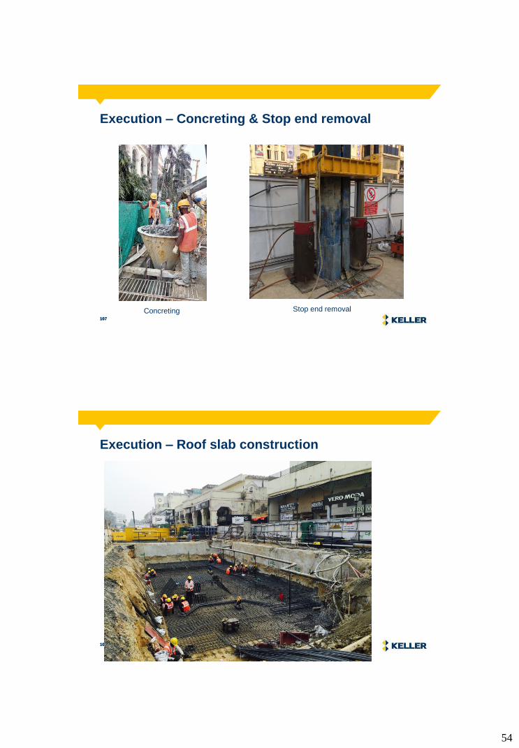
Execution – Concreting & Stop end removal
Concreting Stop end removal
108 108 108
Execution – Roof slab construction

55
109 109 109
Execution – Excavated Portion
110 110 110
Quality Checks for Polymer

56
111 111 111
Quality Checks – Koden Results
• Ground Improvement Techniques such as Deep Vibro Techniques can
be used to provide Optimal Solutions
• Design & Build expertise will ensure savings in Cost & Time
• Execution of Specialized Foundation Techniques requires state-of-the-
art experience with Operational Excellence and Best Practices
• Execution of Deep BCIS Piles requires state-of-the-art process
• International standard of practices using latest equipment ensures the
success of a project
• Safety goal of zero accidents is possible with dedicated safety systems
and motivated leadership
Conclusions

57
Independent Foundation Package
• Allows for specialist foundation works with defined specifications
• Quality works will be delivered in a timely manner
• Combination of heavy foundations (bored piles) and open foundation (ground improvement techniques) for overall cost optimization
• Organisations following the above • HPCL • BPCL • MRPL • IOCL • BHEL
Keller’s Ideal Worker (Kelwin)

58
All the best & Good Luck…..!
Thank you for your kind attention…….!
What Keller do…….?
BCIS Piles
Soil Anchors
DSM
Micro Piles
Grouting
Tank Foundations Stone Columns
Driven Piles