understanding motor and gear drive nameplate information
TRANSCRIPT

Division of Agricultural Sciences and Natural Resources • Oklahoma State University
BAE-1292
Oklahoma Cooperative Extension Fact Sheets are also available on our website at:
facts.okstate.edu
Oklahoma Cooperative Extension Service
Divya HandaGraduate Research Assistant
Saleh Taghvaeian Assistant Professor and Extension Specialist, Water Resources
R. Scott FrazierAssociate Professor and Extension Specialist, Energy Management
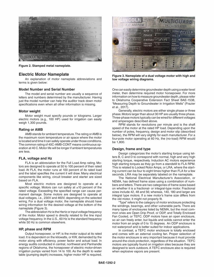
Electric-powered irrigation pumps are widely used in the U.S. In 2013, nearly 428,000 irrigation pumps were powered by electric motors in the U.S. (Farm and ranch irrigation survey, 2013). As such, there are significant opportunities for energy savings that can be achieved by improving the performance of irrigation pumping plants. Conducting energy audit studies helps in assessing the efficiency of these systems. One of the most important first steps is to accurately identify installed equipment. Original installation notes or manuals are often lost, leaving it up to the energy auditor to identify the make, model and serial numbers of pumping plant system components. In the case of electric motors and gear drive units, nameplates often remain intact and attached to the equipment, giving the auditor a wide variety of important information to accurately evaluate system efficiency. Figure 1 shows a complete listing of the various parameters of interest for a gear drive and a typical three-phase AC induc-tion motor. This is the most common motor found in irrigation systems and most of industry in general. Basic knowledge of the terms listed on a nameplate allows the auditor to better understand the performance limits of the motor and gear drive, as well as their combined efficiency. The purpose of this Fact Sheet is to explain the meaning and purpose of nameplate information and show how to use nameplate and measured motor speed to calculate motor loading. Nameplate information gives the auditor a snapshot un-derstanding of several important operating limits. For example, if the motor’s nameplate Full Load Amps (FLA) is 45 and the auditor measures 50, then excessive Amp-pull or load is highly likely. Alternatively, if 15 Amps on a 45 FLA motor is measured, the motor is very under-loaded and operating inefficiently. Sig-nificant deviations in measured operating levels from nameplate information identify specific problem areas. Not all motor manufacturers stamp all information given in Figure 1 on the nameplate. As federal energy efficiency guidelines for motors has increased (Energy Policy Act 1975), nameplate information has become more complete. Therefore, older motors may have only basic information; and just because a nameplate is still attached to equipment does not guarantee its legibility. In irrigation audits, the equipment can be old and weather-beaten due to constant exposure to the elements. Normally, there are two ways to display information on a nameplate. The first is stamping a metal plate (Figure 2). This method normally prevents component information from fading over time. Sometimes the descriptive name where the
Understanding Motor and Gear Drive Nameplate Information
for Irrigation Pump EvaluationsMay 2018
Figure 1. Common nameplate information found on gear-head housings and AC motors.
stamped data is located cannot be read, but if one is familiar with the data fields it is easy to guess the category of data. A second way is the information is painted on a metal or plastic plate riveted to the component. This becomes problematic with older equipment because painted data fades under sunlight or is wiped off by solvents or abrasion. In this case, the auditor has little to start with.
BAE-1292-2
Electric Motor Nameplate An explanation of motor nameplate abbreviations and terms is given below:
Model Number and Serial Number The model and serial number are usually a sequence of letters and numbers determined by the manufacturer. Having just the model number can help the auditor track down motor specifications even when all other information is missing.
Motor weight Motor weight must specify pounds or kilograms. Larger electric motors (e.g., 100 HP) used for irrigation can easily weigh 1,300 pounds.
Rating or AMB AMB stands for ambient temperature. The rating or AMB is the maximum room temperature or air space where the motor is located and time it can safely operate under those conditions. The common rating of 40C-AMB-CONT means continuous op-eration at 40 C. Motor life will be longer if ambient temperatures are less.
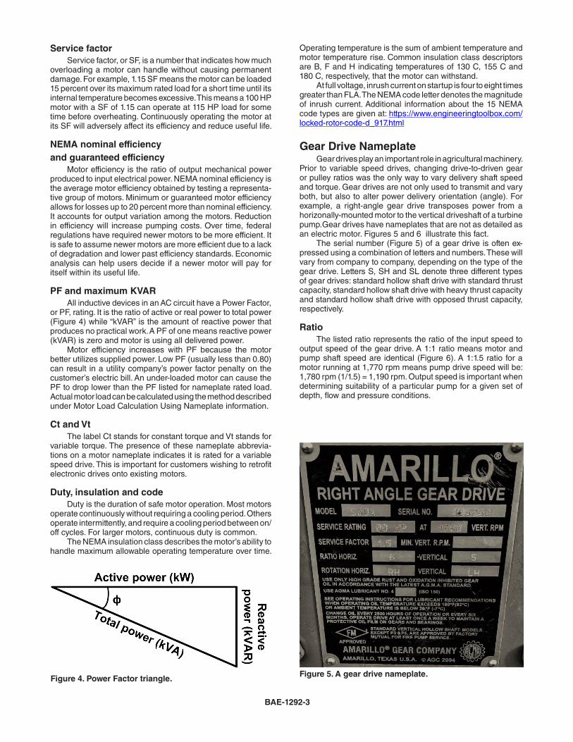
FLA, voltage and Hz FLA is an abbreviation for the Full Load Amp rating. Mo-tors are designed to operate at 50 to 100 percent of their rated load. At FLA, the motor runs at 100 percent of its rated load and the label specifies the current it will draw. Many electrical components like wiring, circuit breaker and starter are sized based on FLA. Most electric motors are designed to operate at a specific voltage. Motors can run safely at ±10 percent of the rated voltage. Exceeding the specified range can cause per-manent damage. Some motors are designed to operate at dual voltages, i.e., 230V and 460V, depending on the selected wiring. For a dual voltage motor, the nameplate should have wiring information for the desired voltage at the bottom of the nameplate (Figure 3). The abbreviation Hz is the Hertz or input voltage frequency of the motor. Motor speed is directly related to the line input voltage frequency. In the U.S., 60 Hz is the standard frequency while 50 Hz is common elsewhere.
HP, phase and RPM Output horsepower, or HP, is the motor output at its rated load. It is dependent on the kilowatts, or KW, demanded by the motor along with efficiency, power factor and actual load. In energy audits conducted in central, northwest and Panhandle regions of Oklahoma, the horsepower of electric motor-driven irrigation pumps varied from 14 to 100. As the depth to water table (pumping depth) increases, higher motor HP is required.
One can easily determine groundwater depth using a water level meter, then determine required motor horsepower. For more information on how to measure groundwater depth, please refer to Oklahoma Cooperative Extension Fact Sheet BAE-1538, “Measuring Depth to Groundwater in Irrigation Wells” (Frazier et al., 2017). Generally, electric motors are either single phase or three phase. Motors larger than about 30 HP are usually three phase. Three-phase motors typically can be wired for different voltages and amperages described above. RPM stands for revolutions per minute and is the shaft speed of the motor at the rated HP load. Depending upon the number of poles, frequency, design and motor slip (described below), the RPM will vary slightly for each manufacturer. For a four-pole motor operating at 60 Hz, the (no-load) RPM would be 1,800.
Design, frame and type Design categorizes the motor’s starting torque using let-ters B, C and D to correspond with normal, high and very high starting torque, respectively. Induction AC motors experience high starting torques as they go from a standstill to FLA RPM. This is related to Locked Rotor Amps, or LRA, where the start-ing current can be four to eight times higher than FLA for a few seconds. LRA may be separately labeled on the nameplate. The National Electrical Manufacturer’s Association, or NEMA, has defined frame sizes using a combination of num-bers and letters. There are two categories of frame sizes based on whether it is a fractional- or integral-type motor. Fractional sizes include 42, 48 and 56; whereas, 140, 180 and larger are integral type motors. If a new motor’s frame size differs from the old motor, it might not properly fit. “Type” refers to the category of motor enclosure protecting the windings, bearings, and other vulnerable parts. There are many types of enclosures listed by NEMA, but the most com-mon ones are Open Drip Proof, or ODP, and Totally Enclosed Fan Cooled, or TEFC. ODP motors have an open enclosure, so air can freely enter, but liquids and solids cannot enter the motor from an angle of 0 to 15 degrees. An ODP enclosure is not waterproof and is better suited for indoor applications. In contrast, a TEFC motor enclosure is totally enclosed and comes with an external cooling fan. Proper selection of the motor enclosure is very important because it must provide around-the-clock protection, regardless of the situation. TEFC motors are typically found on irrigation sites because they are designed to work outdoors. A TEFC enclosure also is required when explosive vapors are present.
Figure 2. Stamped metal nameplate.
Figure 3. Nameplate of a dual voltage motor with high and low voltage wiring diagrams.
BAE-1292-3
Service factor Service factor, or SF, is a number that indicates how much overloading a motor can handle without causing permanent damage. For example, 1.15 SF means the motor can be loaded 15 percent over its maximum rated load for a short time until its internal temperature becomes excessive. This means a 100 HP motor with a SF of 1.15 can operate at 115 HP load for some time before overheating. Continuously operating the motor at its SF will adversely affect its efficiency and reduce useful life.
NEMA nominal efficiency and guaranteed efficiency Motor efficiency is the ratio of output mechanical power produced to input electrical power. NEMA nominal efficiency is the average motor efficiency obtained by testing a representa-tive group of motors. Minimum or guaranteed motor efficiency allows for losses up to 20 percent more than nominal efficiency. It accounts for output variation among the motors. Reduction in efficiency will increase pumping costs. Over time, federal regulations have required newer motors to be more efficient. It is safe to assume newer motors are more efficient due to a lack of degradation and lower past efficiency standards. Economic analysis can help users decide if a newer motor will pay for itself within its useful life.
PF and maximum KVAR All inductive devices in an AC circuit have a Power Factor, or PF, rating. It is the ratio of active or real power to total power (Figure 4) while “kVAR” is the amount of reactive power that produces no practical work. A PF of one means reactive power (kVAR) is zero and motor is using all delivered power. Motor efficiency increases with PF because the motor better utilizes supplied power. Low PF (usually less than 0.80) can result in a utility company’s power factor penalty on the customer’s electric bill. An under-loaded motor can cause the PF to drop lower than the PF listed for nameplate rated load. Actual motor load can be calculated using the method described under Motor Load Calculation Using Nameplate information.
Ct and Vt The label Ct stands for constant torque and Vt stands for variable torque. The presence of these nameplate abbrevia-tions on a motor nameplate indicates it is rated for a variable speed drive. This is important for customers wishing to retrofit electronic drives onto existing motors.
Duty, insulation and code Duty is the duration of safe motor operation. Most motors operate continuously without requiring a cooling period. Others operate intermittently, and require a cooling period between on/off cycles. For larger motors, continuous duty is common. The NEMA insulation class describes the motor’s ability to handle maximum allowable operating temperature over time.
Operating temperature is the sum of ambient temperature and motor temperature rise. Common insulation class descriptors are B, F and H indicating temperatures of 130 C, 155 C and 180 C, respectively, that the motor can withstand. At full voltage, inrush current on startup is four to eight times greater than FLA. The NEMA code letter denotes the magnitude of inrush current. Additional information about the 15 NEMA code types are given at: https://www.engineeringtoolbox.com/locked-rotor-code-d_917.html
Gear Drive Nameplate Gear drives play an important role in agricultural machinery. Prior to variable speed drives, changing drive-to-driven gear or pulley ratios was the only way to vary delivery shaft speed and torque. Gear drives are not only used to transmit and vary both, but also to alter power delivery orientation (angle). For example, a right-angle gear drive transposes power from a horizonally-mounted motor to the vertical driveshaft of a turbine pump.Gear drives have nameplates that are not as detailed as an electric motor. Figures 5 and 6 illustrate this fact. The serial number (Figure 5) of a gear drive is often ex-pressed using a combination of letters and numbers. These will vary from company to company, depending on the type of the gear drive. Letters S, SH and SL denote three different types of gear drives: standard hollow shaft drive with standard thrust capacity, standard hollow shaft drive with heavy thrust capacity and standard hollow shaft drive with opposed thrust capacity, respectively.
Ratio The listed ratio represents the ratio of the input speed to output speed of the gear drive. A 1:1 ratio means motor and pump shaft speed are identical (Figure 6). A 1:1.5 ratio for a motor running at 1,770 rpm means pump drive speed will be: 1,780 rpm (1/1.5) = 1,190 rpm. Output speed is important when determining suitability of a particular pump for a given set of depth, flow and pressure conditions.
Figure 4. Power Factor triangle. Figure 5. A gear drive nameplate.

BAE-1292-4
Oklahoma State University, in compliance with Title VI and VII of the Civil Rights Act of 1964, Executive Order 11246 as amended, and Title IX of the Education Amendments of 1972 (Higher Education Act), the Americans with Disabilities Act of 1990, and other federal and state laws and regulations, does not discriminate on the basis of race, color, national origin, genetic information, sex, age, sexual orientation, gender identity, religion, disability, or status as a veteran, in any of its policies, practices or procedures. This provision includes, but is not limited to admissions, employment, financial aid, and educational services. The Director of Equal Opportunity, 408 Whitehurst, OSU, Stillwater, OK 74078-1035; Phone 405-744-5371; email: [email protected] has been designated to handle inquiries regarding non-discrimination policies: Director of Equal Opportunity. Any person (student, faculty, or staff) who believes that discriminatory practices have been engaged in based on gender may discuss his or her concerns and file informal or formal complaints of possible violations of Title IX with OSU’s Title IX Coordinator 405-744-9154. Issued in furtherance of Cooperative Extension work, acts of May 8 and June 30, 1914, in cooperation with the U.S. Department of Agriculture, Director of Oklahoma Cooperative Extension Service, Oklahoma State University, Stillwater, Oklahoma. This publication is printed and issued by Oklahoma State University as authorized by the Vice President for Agricultural Programs and has been prepared and distributed at a cost of 20 cents per copy. 0418 GH.
Oil specifications Oil and lubrication requirements are often specified on the gear drive nameplate. Only use the recommended oil type and grade. Oil flow rate recommended by the manufacturer should be followed. Normally, a drip oiling system supplies needed lubrication. Following the manufacturer’s recommendations will prevent over-oiling that will contaminate groundwater or under-oiling that leads to premature wear and tear.
RPM RPM stands for recommended revolutions per minute of the gear drive. The rpm of a gear drive unit is proportional to the rpm of the attached motor. The input rpm of the gear drive should match the output rpm of the motor. Mismatched motor/gear drive rpm (e.g., 1,800 vs 3,600 rpm) could lead to premature failure of the gear drive. Some of the additional specifications that are unique to the manufacturer and general requirement like oil capacity may often be found on the nameplate.
Motor Load Calculation Using Nameplate Information This section gives an example of how to use nameplate information to determine motor loading or slip, also known as Slip Calculation. Actual efficiency of an AC induction motor depends on motor load. Maximum efficiency is realized when the motor is operating near 75 percent or more of its maximum rated load. In contrast, actual efficiency significantly decreases when load drops below 50 percent of the maximum rated load (Challenge, M., 1997).
One of the easiest ways to determine load is to calculate “slip.” Full or design load slip is the difference between full load speed and no-load speed. Full load speed is motor rpm at its rated voltage at maximum rated load. No load speed is higher than full load speed because there is minimal resistance to movement. No-load synchronous speeds of 3,600; 1,800; 1,200 and 900 RPM correspond with 2-, 4-, 6- and 8-pole motors, respectively. No load speed is inversely related to the number of poles of the motor. A greater number of poles proportionately decreases rpm. Information about full load rpm and design horsepower can be found on the nameplate. Sometimes the no-load rpm is not listed. However, the full load rpm will be close to 1,800 or 3,600 rpm. Actual load is the ratio of true slip to design slip. True slip is the difference between synchronous and measured rpm. A tachometer is used to measure the actual speed. An example on how to calculate load is below. Given: Full Load rpm (FLRPM) = 1,770 No Load rpm (NLRPM) = 1,800 Measured rpm = 1,780 Design hp = 60
Required: Calculate a) design slip, b) true slip, c) percent load and d) true load. Solution:a) Design Slip = NLRPM – FLRPM = 1,800 – 1,770 = 30b) True Slip = NLRPM – Measured RPM = 1800 – 1780 = 20
c) % load = = = 0.67 or 67%
d) True load = design HP x % load = 60 hp × 0.67 = 40 hp
In this particular case, the motor will operate efficiently as it is loaded above 50 percent.
Acknowledgment This material is based on work supported by the Natural Resources Conservation Service (NRCS), U.S. Department of Agriculture (USDA), under number 69-3A75-16-013. Funding was also provided by the Agricultural Research Service, USDA, under number 3070-13000-011-47S. The authors are thankful to Dr. Don Sternitzke, the Water Management Specialist with NRCS Oklahoma State Office for his valuable comments.
ReferencesChallenge, M. (1997). Determining Electric Motor Load and
Efficiency. Program of the US Department of Energy.Energy Policy Act (1975). Electric Motor Regulations.Farm and Ranch Irrigation Survey (2013). Accessed on Feb-
ruary 2018 at: https://www.agcensus.usda.gov/Publica-tions/2012/Online_Resources/Farm_and_Ranch_Irriga-tion_Survey/fris13_1_012_012.pdf
Frazier, R.S., Taghvaeian, S., Handa, D. (2017) Measuring Depth to Groundwater in Irrigation Wells. Oklahoma Cooperative Extension Fact Sheet BAE-1583. Link: http://pods.dasnr.okstate.edu/docushare/dsweb/Get/Document-10865/BAE-1538web.pdf
Figure 6. Gear Drive nameplate for a 1:1 (non-reduction) drive ratio.
True SlipDesign Slip
2030