understanding and expediting the msha intrinsic safety ... · understanding and expediting the msha...
TRANSCRIPT
UNDERSTANDING AND EXPEDITING THE MSHA INTRINSIC SAFETY APPROVAL PROCESS
Frequently Asked Questions and Guide
_________________________________________________________________
U.S. Department of Labor Mine Safety and Health Administration Approval and Certification Center Electrical Safety Division Intrinsic Safety and Instrumentation Group June 11, 2015 Note: This guide was originally written October 6, 2000 and was only recently updated to match the corresponding sections of the latest version of ACRI2001. MSHA requirements have been modified from the time this was originally written. Refer to the latest version of ACRI2001 and other applicable documents at the following link http://www.msha.gov/Techsupp/ACC/Approvals/ESD/ESDApprovals.asp.
UNDERSTANDING AND EXPEDITING THE MSHA INTRINSIC SAFETY
APPROVAL PROCESS Frequently Asked Questions and Guide
TABLE OF CONTENTS
Section/Title Page
2
Introduction ................................................................................................................................. 4
1) Avoiding Common Application Pitfalls ............................................................................ 4
1.1) Submitting a drawing list .................................................................................... 4 1.2) Submitting a complete drawing package.......................................................... 4 1.3) Submitting equipment and component samples ............................................ 5 1.4) Submitting a completed checklist ...................................................................... 5 1.5) Submitting a factory inspection form or certified statement ........................ 5 1.6) Assigning a company application code number ............................................. 6 1.7) Submitting a technical description of circuit operation ................................. 6 1.8) Class 1, Division 1, Group D versus MSHA approval ................................... 6 1.9) Pre-application review of design ........................................................................ 6 1.10) Certification or approval of individual components ...................................... 7 1.11) When is MSHA approval needed ....................................................................... 7 1.12) Use of MSHA approved equipment in Class 1, Division 1, Hazardous
Locations ................................................................................................................. 7
2) Avoiding Common Drawing Documentation Pitfalls .................................................... 8
2.1) Common administrative drawing omissions ................................................... 8 2.2) Common technical drawing omissions ............................................................. 8 2.3) MSHA approval label information .................................................................. 10 2.4) Drawing documentation for purchased electronic assemblies ................... 10 2.5) Documenting previously evaluated sub-systems ......................................... 11 2.6) Configuring drawings for flexibility in making design changes .............. 11 2.7) MSHA versus foreign and domestic NRTL requirements for detailed
documentation ..................................................................................................... 13
3) Common Discrepancy Letter and Test Failure Questions ............................................ 14
3.1) Partial responses to MSHA discrepancy letters ............................................. 14 3.2) Application cancellation due to lack of response in three months ............ 14 3.3) Cancellation due to total response time in excess of 52 weeks ................... 14 3.4) Fees exceeding the original estimate................................................................ 14 3.5) Correcting printed circuit board spacing problems ...................................... 14
UNDERSTANDING AND EXPEDITING THE MSHA INTRINSIC SAFETY
APPROVAL PROCESS Frequently Asked Questions and Guide
TABLE OF CONTENTS
Section/Title Page
3
4) Avoiding Common Technical Design Problems in Applying Intrinsic Safety Criteria ACRI2001 ..................................................................................................................... 15
4.1) Common battery pack design pitfalls.............................................................. 15 4.2) Common problems involving fuses ................................................................. 16 4.3) Use of Polyswitch type devices ......................................................................... 16 4.4) How MSHA applies circuit faults .................................................................... 16 4.5) How circuit faults are applied for large systems ........................................... 17 4.6) Field wiring faults ............................................................................................... 17 4.7) Dust resistant enclosures .................................................................................... 18 4.8) Voltage threshold level for intrinsic safety .................................................... 18 4.9) Lithium battery design application pitfalls .................................................... 18 4.10) Problems with designs requiring spark ignition testing ............................. 20 4.11) Problems associated with the use of piezoelectric devices .......................... 22 4.12) Problems with the use of voltage converter/inverter circuits ..................... 23 4.13) Optical isolator requirements ............................................................................ 24 4.14) Spark ignition testing of electric motors ......................................................... 25 4.15) Spark ignition testing of circuit powered by constant voltage
transformers .......................................................................................................... 25 4.16) Problems associated with the application of isolating relays ..................... 25
5) Intrinsic Safety Design Tips and Problem Solutions .................................................... 26
5.1) Shunt protective diodes for inductive components ...................................... 26 5.2) Use of shielding in multiconductor cables to isolated intrinsically safe
circuits .................................................................................................................... 26 5.3) Advantages of using a dust-tight enclosure ................................................... 26 5.4) Circuit capacitance and inductance design tips ............................................. 27 5.5) Circuit capacitance isolation tips when system capacitance is too high ... 28 5.6) Use of zener diodes to clamp voltage on large capacitors ........................... 29 5.7) Use of spark suppression diodes on inductive components ....................... 29 5.8) Intrinsically safe primary batteries .................................................................. 30 5.9) Eliminating current limiting resistor tests ...................................................... 31 5.10) Eliminating resistor surface temperature tests............................................... 31
4
Understanding And Expediting The MSHA Intrinsic Safety Approval Process Frequently Asked Questions And Guide
Introduction This guide provides answers to frequently asked questions by applicants seeking MSHA approval or evaluation of intrinsically safe apparatus and associated apparatus. This guide supplements MSHA documents ASAP2016, “Application Procedure for Approval or Intrinsic Safety Evaluation of Intrinsically Safe Apparatus and Associated Apparatus Per 30 CFR Part 18" and ACRI2001, “Criteria for the Evaluation and Test of Intrinsically Safe Apparatus and Associated Apparatus.” Guidance is provided for submitting a complete and effective approval application, avoiding common pitfalls and processing delays. The guide addresses drawing documentation and provides hints for submitting documentation that is adequate in addressing intrinsic safety concerns yet simplified to the extent possible to allow easier investigation and reduce discrepancy letters and future applications for MSHA approval of design changes. Guidance is provided for avoiding common problem areas in understanding and applying MSHA’s Intrinsic Safety Acceptance Criteria. Intrinsic safety design hints and tips are given to avoid common circuit design problems. This guide addresses the most common problem areas encountered in approval applications. Reference to ASAP2016 and ACRI2001 should be made for complete information. 1) Avoiding Common Application Pitfalls
1.1) Why is it important to submit a drawing list and a copy of each drawing on the list with the application letter?
A complete drawing list shows each drawing applicable to the design submitted for approval; both new drawings and drawings already on file with MSHA. The title, drawing number, and revision level, of all drawings must be listed. A complete set of drawings should accompany the application letter and drawing list. This is also important to prepare an accurate fee estimate. The submission of application documentation by computer diskette or electronic submission is encouraged. A complete drawing list and set of drawings allows the MSHA investigator to begin the investigation without delays. An updated drawing list should be submitted when revised or new drawings are submitted during the course of the investigation.
1.2) My design is not quite finalized and my drawings are not complete yet. Can I submit my application letter with an incomplete drawing list and minimum drawings to get my place in the approval backlog queue? I’ll have more drawings completed by the time the application is assigned to an
5
investigator and I’d like MSHA’s advice on alternative designs. Only completed designs with complete drawing packages should be submitted for approval. An accurate fee estimate can’t be provided with an incomplete drawing package. The MSHA investigation process should not be used as part of the design process. The investigation process is to determine whether or not a completed and submitted design meets MSHA’s requirements, not to evaluate alternative design approaches. The submission of incomplete and tentative designs is one of the reasons a backlog exists. It results in multiple discrepancy letters and applicant response cycles and fee re-estimates that slow down the approval process. In too many cases of inadequate applications, the final drawing package is not available when the investigator starts the evaluation. The approval backlog that results affects all applicants, and particularly hurts those that have a complete design and application package.
1.3) Is it necessary to submit equipment and component samples with my approval application or can I wait until they are requested by the investigator? Although you may wait until the investigator requests the samples, it will expedite the approval process if samples are submitted with your approval application. This will allow the investigator to inspect the samples as he reviews the drawings and avoids the delays created by a formal request for samples and delayed equipment inspection.
If any assemblies are normally potted or encapsulated, both encapsulated and unencapsulated samples must be submitted. Special tools required for disassembly of equipment samples must be provided.
1.4) Why must I submit a completed checklist, Enclosure C, of the Application Procedure?
The checklist is primarily for the benefit of the applicant to ensure that a complete application has been prepared. If all items are addressed, then a complete application has been prepared which will expedite the approval.
1.5) Why do some applications require a submission of a Factory Inspection Form or Certified Statement (Enclosure D of Application Procedure) while other applications don’t seem to require them?
The factory inspection form or certified statement is only required for products submitted for approval under 30 CFR, Part 18.
6
1.6) How do I find out what my company assigned application code number is? This number, up to six digits, is assigned by you, the applicant. You should use a unique number which has not been used on prior applications.
1.7) Why is a technical description of circuit operation requested?
For large systems and complicated circuits this can expedite the approval process by helping the investigator determine worst case voltage and current levels when fault conditions are considered in the circuit. Emphasis should be placed on explaining the design approach taken to achieve intrinsic safety and identifying protective components used in the circuit.
1.8) I have UL and FM intrinsic safety approval of my equipment for hazardous locations classified Class 1, Division 1, Group D. The application procedure requests copies of test reports from other approval agencies. Will you approve my equipment on the basis of the other agency’s evaluation and tests?
MSHA can accept the results of tests and evaluations if they are conducted according to MSHA’s requirements. For more information , see http://www.msha.gov/Part6SingleSource/Part6SingleSource.asp. MSHA does not issue intrinsic safety approvals on the basis of another agency’s approval or certification. However, having the report may expedite the approval since the investigator can review the test conditions and results, and can determine what standard or criteria the design has already met. Testing will be conducted to confirm conformance to MSHA’s requirements. The only exception to this is for passive shunt diode barrier assemblies consisting of zener diode, resistor and fuse components. Shunt diode barrier assemblies tested and listed by a nationally recognized testing laboratory may be considered suitable, without MSHA testing, if the test report is submitted to MSHA and the report and manufacturer’s specifications indicate the barrier meets the requirements of MSHA Intrinsic Safety Criteria, ACRI2001, Sections 8.7.1 through 8.7.7.
1.9) I’m not sure if my design has a chance of being approved or if my drawing documentation is adequate. Is there any way that MSHA can perform a preliminary review of my design before I make official application?
You can request a consultation meeting. A cursory review of your design will be made and verbal comments passed on to you concerning potential problem areas. Experience has shown that these consultations result in a more complete
7
application package with fewer discrepancies; resulting in shorter approval time.
1.10) Does MSHA list, certify or approve individual electrical components for intrinsic safety?
MSHA typically only approves or evaluates powered electrical circuits, assemblies or components. An individual component, such as a switch, connector, relay, solenoid, etc., that is not part of a powered electrical circuit can not be evaluated for intrinsic safety. MSHA does not recognize the entity parameter assignment concept used in above-ground and some foreign mining applications which allows the configuration of an intrinsically safe powered system in the field by the end user.
1.11) When do I need MSHA approval or evaluation of my product for use in underground gassy mines?
In coal mines, whenever your electrical product, or part of a system, is intended to be used in or inby the last open crosscut, which includes return air. In other words, only when used in the potentially gassy area of the mine. If it is to be used only in fresh air, outby, then no MSHA approval is required. For metal and non-metal mines, approval is required as follows:
Category I-A and V-A Mines: In or beyond the last open crosscut. Category I-C Mines: Underground Category II-A Mines:
(a) Cutting and drilling equipment used at a face or bench. (b) While cutting or drilling is in progress, at least 100 feet from the face or bench being mined.
Category III Mines: In or beyond the last open crosscut and equipment used in areas where methane may enter the air current, such as pillar recovery workings, longwall faces and shortwall faces.
If you have specific questions regarding the location and operation of your equipment at a specific mine, contact your local MSHA field office for advice.
1.12) If I receive MSHA intrinsic safety approval for my equipment, can it be used in industrial areas classified as Class I and Class II, Division 1, Group D Hazardous Locations under Article 500 of the National Electrical Code?
MSHA intrinsic safety approvals are strictly for underground gassy mines and are not considered safe in Class I and Class II, Division 1, locations. Equipment approved by MSHA is tested for use in environments containing methane and
8
coal dust. Although methane is a Group D gas, it is not the most easily ignited Group D gas. Also, equipment which is safe for use in coal dust is not safe for use in other types of dust which may be more electrically conductive, have a lower layer ignition temperature or lower dust cloud minimum ignition energy.
2) Avoiding Common Drawing Documentation Pitfalls
2.1) What are some common administrative drawing omissions that lead to discrepancy letters and approval delays?
a. Not putting the MSHA warning note “Do not change without approval of MSHA” on each page of every drawing and each page of a parts list or bill of material for Part 18 approval applications.
b. Not putting the MSHA warning note “Any changes in the intrinsically safe circuitry or components may result in an unsafe condition” on wiring and schematic diagrams. This is only required for equipment approved under 30CFR, Part 18.
c. Not including the company name, drawing title, drawing number, sheet number, and date or revision, on each page of every drawing and parts list.
d. Illegible or partially legible drawings, sometimes due to print quality and other times due to excessive drawing reduction where nomenclature is too small to read.
e. The presence of pen and pencil notations on drawing prints. These notations are not permitted on drawing prints. They are allowed on the original manufacturer’s drawing.
f. Drawings containing foreign language nomenclature that has not been translated into English. All required administrative and technical nomenclature must be translated into English.
2.2) What are the common technical drawing omissions that lead to discrepancy letters and approval delays?
a. Not submitting a pictorial external view of the equipment showing overall mechanical dimensions and general location of controls, indicator lights and displays.
9
b. No specification of the generic name for enclosure material and a minimum wall thickness. Although detailed fabrication drawings are not required for equipment enclosures, this minimal information along with the overall mechanical dimensions provide a basis for determining suitability for intended use and controlling drop test performance.
c. Failure to identify and show the location, size, material, and method of attachment of the MSHA approval or certification label.
d. Failure to submit a simplified internal assembly drawing showing the major electrical components, PC boards and their interconnection.
e. Failure to submit a complete electrical parts list, schematic diagram, component layout drawing, and PC artwork drawing for each electrical assembly and PC board.
f. Not providing sufficient information to document the applicant’s intent in regard to enclosure sealing. Is the design to be evaluated assuming coal dust entry or is coal dust layering on electrical components prevented by use of a dust resistant enclosure, encapsulation or potting? This is important early in the investigation since it determines whether a 150°C or 530°C maximum component surface temperature criteria is applied.
g. Not providing scaling dimensions on PC artwork drawings. Since reproduction of the drawings often changes the scaling of the drawing, these dimensions are important for assessing proper circuit spacings.
h. Not providing sufficient information for encapsulation or potting materials. The manufacturer, generic name, type designation, voltage rating, and maximum temperature rating, all need to be specified on the drawings.
i. Not providing any or sufficient information for conformal coatings on PC board assemblies. These coatings protect against environmental contamination and allow the circuit to be accepted with closer circuit spacings than would be acceptable if no coatings were provided. The drawings must specify an adherent insulating coating that is at least two layers thick having a minimum dielectric voltage rating of 200 volts per 0.025 mm of thickness or a single layer not less than 0.7 mm thick.
j. Not listing a manufacturer and series number for a fuse. The fuse
10
current rating must be specified and the manufacturer’s current versus time curves submitted.
k. Failure to design and properly document a protective transformer as fitting into one of the five allowable construction categories: Type 1(a), Type 1(b), Type 2(a), Type 2(b) or Type 3 (See ACRI2001, Section 8.2).
l. Failure to specify the printed circuit board minimum thickness and minimum distance between inner layers.
2.3) What information do I need to show on the drawings for the MSHA approval label and how can I get artwork for the MSHA logo?
Other than identifying the location, size, material, and method of attachment of the approval label, your drawings need not show the information contained on the approval or certification label. When the investigation is completed, MSHA will send to you the required approval label information which includes: MSHA logo, approval number, and required warning notes. Since this information isn’t known until the investigation is complete, it is best not to put any approval label information on the drawings.
2.4) I want to use a purchased off-the-shelf type of circuit board or module in my design. MSHA requires detailed drawing documentation but I can’t supply detailed drawings since my company didn’t design and manufacture the product. What can I do?
Since the proprietary nature of their design is of concern to most suppliers, request that they send detailed drawings of their design directly to MSHA. MSHA will not divulge design information to third parties. These drawings, however, still must meet all of MSHA’s administrative drawing requirements and contain the usual “Do not change without approval of MSHA” warning note for Part 18 applications.
If the supplier will not provide any drawings, the applicant may create their own drawings based on inspection of the subassembly and measured component values.
In all instances, it is the applicant’s responsibility for assuring the assembly has been built according to the submitted drawings.
2.5) I want to use previously evaluated intrinsically safe sub-systems, already having an MSHA acceptance number, (e.g., IA-XXXX-XX, 18-ISAXXXXX-X,
11
etc.) in my machinery control system. How do I document this on the system drawing?
As long as you are using the sub-system in its entirety, as described in the MSHA acceptance, and meet all conditions of use, then it is only necessary to show the sub-system as a block on the system block diagram, with interconnection details, and indicate the manufacturer, sub-assembly name, part or model number and MSHA acceptance number and extension number.
If you are only using part of the previously accepted sub-system then it is necessary to obtain from the manufacturer a list of the applicable drawings, to add to your submitted drawing list, and also a letter to MSHA from the manufacturer authorizing release of test and evaluation information for the purposes of processing your application. The sub-system manufacturer’s name, model number and MSHA acceptance number should be referenced in the letter.
2.6) I want to maximize my ability to make post-approval design changes without having to submit them for MSHA approval. How can I configure my drawings to allow flexibility for future changes?
It is the goal of both the applicant and MSHA that the design drawing package be configured to allow the applicant maximum flexibility to make changes without having to submit them for approval through MSHA’s RAMP or extension programs. The submission of RAMP applications for minor changes, that could have been avoided by flexible drawing documentation, contributes to MSHA backlogs and slows down the approval process.
The key to flexible and simplified documentation comes through a basic understanding of intrinsic safety design and MSHA’s Intrinsic Safety Criteria, ACRI2001. With this knowledge, a documentation package can be prepared to provide detail only in the areas necessary to determine and control intrinsic safety and allow flexibility for change in areas not critical for intrinsic safety. In general, applicants who submit their manufacturing drawings for an intrinsic safety evaluation are unnecessarily limiting themselves for making future changes because these manufacturing drawings contain too much detail and very specific part specifications. The applicants that end up with the most flexible documentation package for future changes are those that and configure special drawings specifically for the intrinsic safety application submission. However, an applicant may always submit manufacturing documents if they do not wish to create special approval drawings.
One way to reduce evaluation time is to avoid submitting drawings containing
12
duplicate or unnecessary information. MSHA investigators must compare the submitted drawings with a sample unit to ensure the unit is assembled according to the submitted drawings. The more unnecessary information that is submitted, the more time must be spent comparing components on the sample unit to the drawings. An example where time is wasted is when a detailed electrical parts list and a schematic are submitted with component values and specifications. A cross check then has to be made comparing the parts list with the schematic. Many times discrepancies are found where the component values don’t agree. It is better to either put all of the electrical parts list information on the schematic diagram or to leave all parts values off of the schematic and only list them on the electrical parts list.
Except for equipment approved under 30 CFR Parts 19, 22, 23 & 27, requiring performance tests, equipment typically approved under 30 CFR Parts 18 or 20, only requires documentation sufficient for making a determination of intrinsic safety. This allows considerable latitude in specifying electrical components. Of course there are certain components that are critical to maintaining intrinsic safety, (e.g. protective current limiting resistors, transformers, optical isolators, and shunt protective diodes). Protective components always require detailed specifications. Components that are accepted on the basis of MSHA testing also require detailed specifications, including manufacturer and part number.
Many components, although potentially affecting intrinsic safety, are not considered critical components. With these, you have considerable flexibility in documenting their specifications. For example, it is the maximum capacitance that is of concern in the intrinsic safety analysis, so only maximum capacitor values need be specified, which should include tolerances. Only minimum voltage ratings and generic type need to be specified for capacitors. The manufacturer and part number need not be specified.
For inductors, it is only the maximum inductance that needs to be specified along with the minimum DC resistance of the inductor. The manufacturer and part number need not be specified.
A range of value or minimum ohmic value, the minimum wattage rating, and the generic type, may be specified for resistors. Specifying metal film or wirewound resistors is advantageous because they can be accepted as a protective resistor, not subject to fault, without testing when they are subjected to less than two-thirds their power dissipation rating under fault conditions. This can considerably reduce the number of fault scenarios that need to be considered in the intrinsic safety analysis. The manufacturer and part number need not be specified.
13
When the current to a circuit is limited to less than one ampere, semiconductor devices such as integrated circuits, transistors and diodes do not typically pose any thermal ignition concerns. In these cases the devices may be identified only by their generic function, with no specification of manufacturer or part number. When there may be thermal concerns, specify only the JEDEC, 1N....., 2N...., numbers for transistors and diodes without the manufacturer’s name and specify only the center generic number for an integrated circuit, minus the prefix and suffix alpha-numeric characters that designate a specific integrated circuit manufacturer and mechanical package.
Mechanical detail should be minimized on your drawings to allow flexibility for future mechanical changes. The primary mechanical documentation concerns for Part 18 and Part 23 approvals are to provide enough detail to allow a determination of suitability for intended use and for controlling drop test performance, and enclosure sealing, when applicable. Typically a pictorial external view of the equipment showing overall mechanical dimensions and general location of controls, indicator lights and displays, and a specification of the generic name for the enclosure material and a minimum wall thickness should be provided. A simplified internal assembly drawing should be submitted showing the major electrical components, PC boards, and their interconnection. Detailed fabrication drawings for enclosures and other mechanical parts need not be submitted.
2.7) Why does MSHA seem to require more detailed documentation than required for other foreign and domestic NRTL intrinsic safety approvals?
MSHA’s regulations don’t allow for post approval factory follow-up audits to ensure a product continues to be built according to the original approved design. Since the MSHA approval is good for the life of the product, with no factory audits, the documentation must be more complete and detailed to control the design.
14
3) Common Discrepancy Letter and Test Failure Questions
3.1) I received a discrepancy letter from MSHA and it gives me three months to correct the discrepancies. I am unable to correct all of the discrepancies in this time period. Is it acceptable to provide a partial response?
Partial responses to discrepancy letters are one of the major factors in extending approval investigation time and adding to the approval backlog. It is important to provide a complete response. If you are unable to make a complete response it is better to request a time extension and to make a complete response. The time extension must include an expected date of response and must be requested in writing by mail, fax, or E-mail. Verbal requests are acceptable but must be followed in writing.
3.2) (DELETED-CANCELLATION COURTESY CALL NOW REQUIRED)
3.3) (DELETED- 52 WEEK TOTAL NO LONGER APPLICABLE)
3.4) I thought the initial approval fee estimate I received was a maximum figure that would not be exceeded. Why did you send me a request for authorizing a higher fee?
The initial fee estimate is calculated assuming minimal discrepancies and that the equipment passes all planned tests. Extensive discrepancies, test failures requiring redesign or retesting, or redesign that is not in response to an MSHA identified discrepancy, result in additional investigation time and a potential increase in the fee estimate.
3.5) I received a discrepancy letter that detailed two areas in the printed circuitry where spacing faults could be applied that created an unsafe circuit condition. I corrected the circuit layout in these areas and resubmitted samples of the PC board. Why was the board layout found unacceptable because of additional spacing problems?
When PC boards are designed with circuit spacings not meeting the requirements of Table 7.1 of ACRI2001, there are usually too many spacing fault scenarios to reasonably consider and document. In the interest of the productive use of their time, the investigator will usually point out a couple of worst case scenarios that result from the spacing fault analysis. These are given as examples where the most obvious applications of clearance and circuit fault analysis identified a potentially hazardous circuit condition. Other combinations of clearance and circuit faults not evaluated may also lead to hazardous circuit
15
conditions. Therefore, circuit revision considerations should not be limited to the examples given. The layout problems can best be solved by following the spacing distances given in Table 7.1, ACRI2001.
4) Avoiding Common Technical Design Problems in Applying Intrinsic Safety Criteria ACRI2001
4.1) What are some common pitfalls in battery pack designs?
a. Failure to locate battery pack protective components such as current limiting resistors and fuses as close to the battery cell terminals as possible for cells requiring energy-limiting components. These components, along with the battery cells, should form an integrated, protected, replaceable tamper-proof assembly through the use of encapsulation or other means. See ACRI2001, Sec.9.3.10.
b. Misapplication of Sec. 9.3.10.2, by using replaceable battery cells, mounted in a battery holder, that are not individually intrinsically safe, and locating energy limiting components such as current limiting resistors or fuses separately in the apparatus, such as on a PC board. This section allows the energy limiting components to be separately mounted from the battery cells only when each individual battery cell in the holder is intrinsically safe.
c. Using the standard battery cell shrink-wrap sleeving provided by most OEM battery pack suppliers. The sleeving is too thin and does not provide the 0.5 mm minimum distance through solid insulation between adjacent battery cells required by Table 7.1 of ACRI2001. With the thin sleeving, it is usually possible to apply spacing faults between the negative cell casings that result in short-circuiting the battery pack before the series current limiting components. The drawings should clearly specify a minimum 0.25 mm cell sleeving thickness so that the total insulation thickness between two adjacent cells totals 0.5 mm.
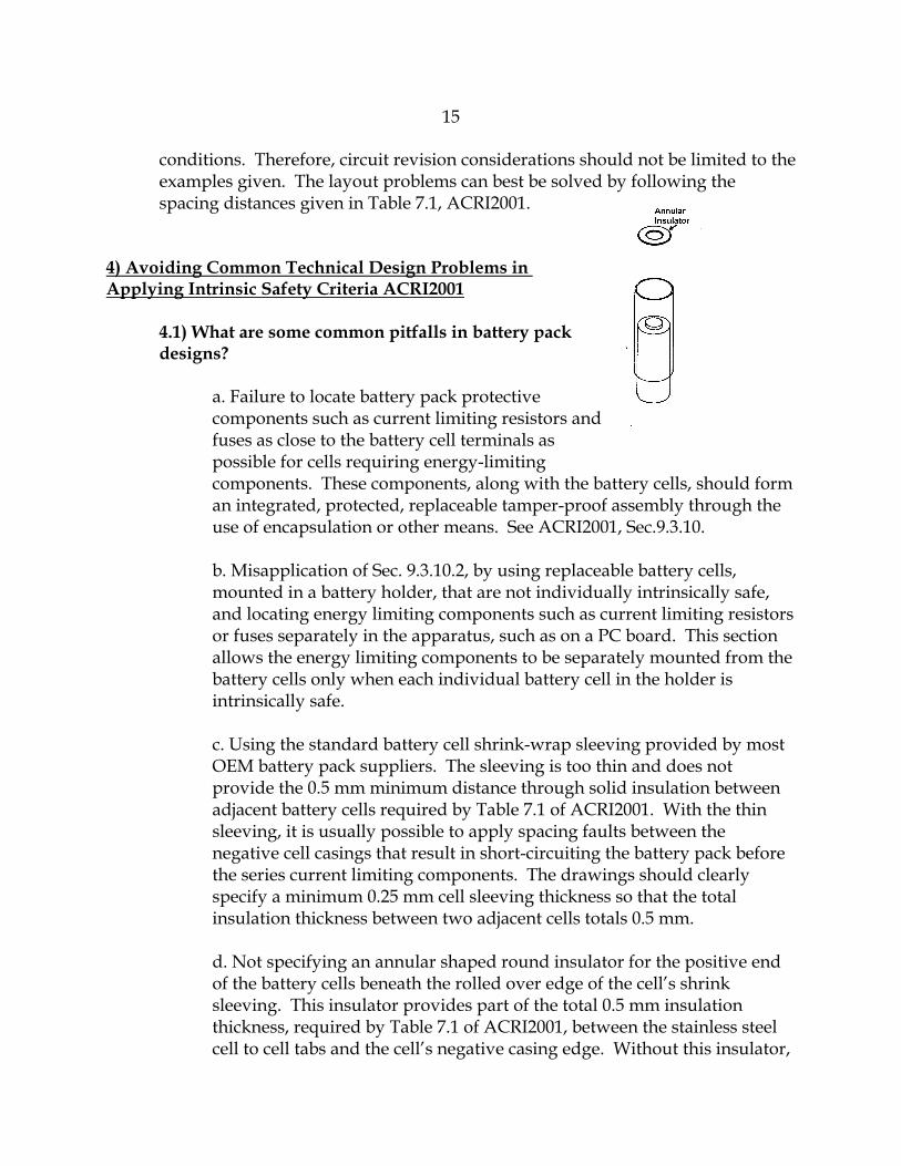
d. Not specifying an annular shaped round insulator for the positive end of the battery cells beneath the rolled over edge of the cell’s shrink sleeving. This insulator provides part of the total 0.5 mm insulation thickness, required by Table 7.1 of ACRI2001, between the stainless steel cell to cell tabs and the cell’s negative casing edge. Without this insulator,
16
a spacing fault may be assumed at this point, short-circuiting the battery cell.
4.2) What are some common problems involving fuses?
a. Misapplying fuses to protect against a spark ignition hazard. Even the fastest blowing fuses do not clear fast enough to prevent a spark ignition. Fuses may only be used to protect other components from becoming thermal ignition sources. See Sec. 8.9.2 of ACRI2001. However, the minimum cold resistance of a fuse can be used in the assessment of spark-ignition risk.
b. Not specifying a fuse meeting the requirements of ACRI2001, Section 8.9 and not providing a manufacturer’s fuse specification sheet. The specification sheet allows the investigator to confirm the current at which that the fuse is rated to open within a maximum two minute time period. Also, the specification sheet helps the investigator determine that the fuse is subjected to no more than two-thirds its maximum interrupt current and voltage rating specifications when considering up to two faults. See Sections 8.9.3 & 8.9.4.
c. Not using a soldered-in type fuse or one welded, brazed, or encapsulated. See Sec. 8.9.4 of ACRI2001.
4.3) Can I specify a Polyswitch, positive temperature coefficient (PTC), type device for thermal protection instead of a fuse?
Unlike a fuse, the longevity, and failure mode characteristics have not been adequately established for MSHA to consider these devices as a protective device, not subject to fault when used for thermal protection. These type of devices may be used redundantly, two or three in series depending on the circuit, or singly in series with a fuse to provide thermal protection, since the PTC device will be considered subject to fault. However, by proper selection of fuse and PTC device parameters it is possible to have the convenience of the automatically resetting Polyswitch type device, when the PTC device trip point is selected to trip before the fuse blows. In this example MSHA would consider the Polyswitch device shorted and evaluate the adequacy of the fuse in providing thermal protection.
4.4) What do I need to know about how MSHA applies circuit faults?
Your circuit must be intrinsically safe under normal conditions and with the assumption of one or two independent circuit faults. In general, circuit
17
components, other than protective components meeting certain construction and test requirements, may be considered to fail open or short-circuited, or at any resistance between these extremes. See ACRI2001, Section 5.3.
Circuit and printed circuit spacings meeting the minimum distance requirements of ACRI2001, Table 7.1, are not subject to fault. However, circuit separation distances between the table values and one third the table value are subject to fault and this fault counts as one of the two allowable circuit faults that MSHA may apply. Circuit separation distances smaller than one third the table values will be considered normally connected by MSHA and will not use up any of the two allowable circuit faults that MSHA may apply. See ACRI2001, Section 7.1.
Consideration of printed circuit board thickness is an area commonly overlooked in designs involving double sided printed circuit boards. This is also a concern with multi-layer printed circuit boards. In Table 7.1 of ACRI2001, the “Distance Through Casting Compound” spacings must be maintained between layers of a printed circuit board for the layers not to be considered subject to fault. Creepage distances along the edge of the printed circuit board also have to meet the requirements of Table 7.1, to avoid being subject to a “layer to layer” fault. The design of multi-layer printed circuit boards presents additional problems for the MSHA investigator in conducting the spacing analysis since the inner layers can’t be visually inspected. Special documentation may be needed to be submitted to allow a spacing analysis in these cases. It will help expedite the evaluation process if multi-layer boards are used only for circuitry where spacing control is not necessary for maintaining intrinsic safety.
4.5) How does MSHA apply circuit faults when determining intrinsic safety in a large system made up of many separate electrical assemblies; two circuit faults in each assembly or just two faults in the entire system?
MSHA may evaluate many two fault scenarios, but only two faults may be applied in any evaluation scenario in the entire system.
4.6) What is considered field wiring and how are field wiring faults counted in the intrinsic safety analysis?
Field wiring is wiring installed by the end user to interconnect the individual pieces of an intrinsically safe system. As such, it is wiring that is not necessarily protected by enclosures and is considered likely to be damaged through use. As a result, field wiring cable conductors are subject to any number of short or open circuit faults, polarity reversal or grounding. These faults are considered as a normal condition and do not use up any of the two allowable circuit faults that
18
may be applied in the circuit evaluation. See ACRI2001, Section 5.2.3.
4.7) If I want my enclosure to be considered dust tight, is it necessary for it to pass a specific dust exclusion test?
If an enclosure has no openings and all joints are either gasket sealed, or threaded with at least three full-thread engagement (see ACRI2001, Section 7.5) it will be considered dust-tight. Alternatively, submission of documentation showing an enclosure passing an appropriate dust test, such as NEMA Publication 250, “Enclosures for Electrical Equipment (1000 Volts maximum),” may be used to establish its dust-tight integrity. Also, MSHA-certified explosion-proof enclosures and enclosures that are rated at least IP5X per IEC 60529 “Degrees of Protection Provided by Enclosures (IP Code)”, are acceptable.
4.8) If I design my circuits to be powered below some threshold voltage level, won’t they be intrinsically safe?
Not necessarily. There is no single voltage threshold level below which all circuits are intrinsically safe. The intrinsic safety of a circuit is dependent on many factors because it is related to the energy that can be released in the form of a spark when making or breaking a circuit connection and also on thermal energy that may be released by a component. Key variables affecting energy released in a spark are the voltage level, current level, capacitance, and inductance of the circuit. The complex interaction of these variables can best be seen in the Ignition Curves, Section 11.0 of ACRI2001. With the consideration of circuit faults and application of appropriate safety factors, the goal is for the circuit to be operating in a region below the applicable ignition curve.
4.9) What are some pitfalls in designs powered by lithium batteries?
Because of concern over the potential for lithium batteries to explode under certain conditions, MSHA has additional requirements that apply to lithium batteries, ACRI2001, Section 9.3.14. Designs submitted with user-replaceable lithium battery cells are not acceptable. The battery cells should only be technician-replaceable. The cells should be soldered to a PC board and encapsulated to the board or located in a sealed enclosure or shrink-wrapped assembly with leads and special connector to connect the battery assembly to a mating connector on a circuit board. The goal is to prevent replacement of the individual cells by the user. A label is to be provided on or near the battery warning against replacement of the cells by the user.
A typical omission by applicants is in not submitting a detailed Report and Test
19
Records by a UL certified laboratory or a lab that has been recognized by a laboratory accrediting organization proving that the lithium battery cell has been tested to “Standard for Lithium Batteries - UL 1642.” Sometimes the test report is submitted but review of the report indicates that some of the test samples exploded or flashed during the UL testing. MSHA will not accept cells that exhibit this behavior, so UL recognition does not necessarily mean the cell will be acceptable to MSHA. The applicant should review the UL test reports before submitting them to MSHA to ensure the test cells did not explode or flash during the testing.
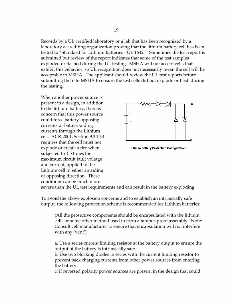
When another power source is present in a design, in addition to the lithium battery, there is concern that this power source could force battery-opposing currents or battery-aiding currents through the Lithium cell. ACRI2001, Section 9.3.14.4 requires that the cell must not explode or create a fire when subjected to 1.5 times the maximum circuit fault voltage and current, applied to the Lithium cell in either an aiding or opposing direction. These conditions can be much more severe than the UL test requirements and can result in the battery exploding.
To avoid the above explosion concerns and to establish an intrinsically safe output, the following protection scheme is recommended for Lithium batteries:
(All the protective components should be encapsulated with the lithium cells or some other method used to form a tamper-proof assembly. Note: Consult cell manufacturer to ensure that encapsulation will not interfere with any ‘vent’)
a. Use a series current limiting resistor at the battery output to ensure the output of the battery is intrinsically safe. b. Use two blocking diodes in series with the current limiting resistor to prevent back charging currents from other power sources from entering the battery. c. If reversed polarity power sources are present in the design that could
20
produce battery aiding currents, use two shunt diodes connected across the output lines of the battery assembly, after the series current limiting resistor and blocking diodes, to shunt aiding currents around the battery assembly.
4.10) What are some of the problems associated with designs requiring spark ignition testing?
Whenever possible, designs should be submitted that can be assessed on the spark ignition curves so that spark ignition testing may be avoided. See ACRI2001, Figures 11.1-11.4. The time consuming nature of spark testing and likelihood of test failures can substantially lengthen the approval time.
Whenever the nature of the design necessitates spark ignition testing there are a number of considerations that can help expedite the process. It helps to understand the problems associated with conducting the test to appreciate why spark ignition testing can be so time consuming. The spark test apparatus consists of four tungsten electrodes rotating against and over a counter-rotating slotted cadmium disc which produces electrical sparks, powered by the circuit under test, in a sealed chamber containing the most easily ignitable gas concentration (See ACRI2001, Section 10.1). A test consists of running the apparatus for 1000 revolutions of the electrode holder which results in a minimum of 4000 make-break sparks. To ensure that the apparatus is operating at proper sensitivity, a calibration check is made before and after the test with a voltage and current level known to produce an ignition. Under ideal conditions, a spark ignition test can be conducted in approximately 30 minutes.
There are a number of typical problems that are encountered with spark ignition testing. The pre-test calibration of the spark test apparatus sometimes can’t be obtained because of weather conditions. Atmospheric pressures and humidity levels affect spark ignition calibrations. When this occurs, much time can be expended on verifying that it is a weather problem and not a gas concentration problem. Testing is then delayed until calibrations can be obtained. Because of the nature of the test apparatus, there is breakage, wear and bending of the electrodes and the formation of carbon deposits on the cadmium disc as the test proceeds. As a result, your circuit may get through the test with no ignitions, but when the post-test calibration is run, no calibration ignition may be obtained, therefore, the test is invalid. The disc will then be cleaned, electrodes replaced and the whole test cycle repeated again.
Always design your circuits to minimize maximum available currents to the extent possible. Lower test current levels reduce cadmium disc contamination and produce less wear on the electrodes. Test currents below 5 amperes allow use of
21
the 8 mil diameter test electrodes which are more flexible and desirable. For test currents between 5 and 10 amperes, 10 mil diameter electrodes are required which are more brittle and subject to breakage. When test currents exceed 10 amperes copper electrodes must be used which are very soft and deform during the test. The change in electrodes is required to prevent thermal ignitions due to thermal heating of the electrode. It usually requires multiple test cycles to get one valid test completed with a proper post-calibration ignition when copper electrodes are used. Whenever possible, in a battery pack design, use sufficient current limiting to limit the short circuit current to less than 10 amperes to expedite the test process.
Because of the rotational characteristics of the spark test apparatus there are certain fixed dwell times where the electrodes are in contact with the cadmium disc and when the apparatus is open-circuited. In an inductive circuit under test, the current must have reached a steady state final value before the circuit is opened by the electrode leaving contact with the disc. With capacitive circuits, there must be enough time where the electrode is not in contact with the disc for the voltage to reach its final steady state value before the electrode again contacts the disc. When these conditions cannot be met, electrodes will be removed from the spark test apparatus to achieve proper dwell times. Unfortunately, operating with only one electrode makes the test take four times as long. Additionally, sometimes the rotational speed of the spark test apparatus has to be reduced for proper timing. This is not desirable and can create difficulty in getting pre and post calibration ignitions.
Some power supply circuits electronically shut down the output after one short circuit spark and keep the circuit latched off. Obviously the spark test can’t be conducted under this condition. The point of these timing problem examples is to make the applicant aware of the test problems so that they can be considered in the design process and avoided. If the circuit can not be properly spark tested, it can never be approved. In the case of the power supply circuits with the latching shutdown circuits, a means should be provided to modify the circuit to automatically and quickly reset the circuit for proper spark testing. It is the applicant’s responsibility to design and supply the additional circuitry necessary to properly spark test these types of circuits. Failure to plan and provide for these testing needs can result in major approval delays. See the Intrinsically Safe Active Voltage/Current Power Source Criteria (ACRI2011) at http://www.msha.gov/techsupp/acc/application/acri2011.pdf for more information.
Another problem area involves the need to conduct the spark ignition test with a safety factor applied to the circuit voltage and current levels. With circuits
22
powered by voltages below 24 volts and a frequency below 60 Hz, the more explosive gas mixture of propane and air may be used to obtain the needed safety factor. But for circuits powered by voltages greater than 24 volts and frequencies greater than 60 Hz, propane-air mixtures may not be used to obtain the needed safety factor. In these cases, the circuits must be capable of adjustment to elevate the voltage and current by a factor of √1.5, for a resistive circuit, to obtain the needed safety factor. If forethought is not given to address this testing need, or if it is not feasible to increase the output by these factors due to the nature of the design, then it may not be possible to spark test and approve the design.
Another problem area develops when the applicant submits a design that fails and then requests MSHA to conduct extensive spark ignition testing to “home-in” on a design that passes. When MSHA is asked to spark test with many variables, for example different combinations of voltage level, protective zener diode voltage, and different quantities of solenoids in parallel, testing time can become excessive. This slows down the approval process and impacts the timely processing of other applications. Since MSHA testing is not to be used as part of the design process by applicants, but rather to confirm that a completed design is safe and meets all applicable requirements, MSHA will conduct spark ignition testing with only minor variation in one test variable. When extensive spark testing is required as part of the design process or in correcting a test failure, it is suggested that the applicant have the spark testing conducted by a private Nationally Recognized Testing Laboratory certified for intrinsic safety testing. After the applicant has a finalized design that passes the spark ignition test, the design should be submitted for final confirmation spark testing by MSHA or the results of the independent laboratory submitted per 30 CFR Part 6.
4.11) What are some of the problems associated with piezoelectric devices?
These devices are commonly used as audible alarms. They contain a crystal that when impacted can generate a peak voltage of hundreds of volts. This is the same principle used by the igniter on your patio gas grill. The safety of these devices must be determined through impact testing (See ACRI2001, Section 9.4) so it’s acceptance is more complicated than for an alarm device operating on electro-magnetic principles. Since the device must be tested in its normal mounting within the product enclosure, the applicant needs to provide the proper number of samples, and possibly special test samples for devices containing internal circuitry, to avoid delays in testing and approval. Three samples of the apparatus, typical of the final manufactured product, containing the piezoelectric component internally mounted need to be submitted. Mockups of the apparatus assembly may be tested
23
in lieu of the actual assembly with prior review and approval of the Intrinsic Safety and Instrumentation Team Leader. Since many of the alarm devices contain internal circuitry in addition to the piezoelectric crystal, the applicant can reduce approval time by supplying special samples of the device made up with the output leads of the device directly connected to the crystal. The capacitance of the crystal must also be specified on a drawing submitted for the device or on a parts list.
4.12) What problems do the use of voltage inverter or converter type circuits in a circuit design present in the intrinsic safety evaluation process?
The use of any voltage generating component or circuit in a design needs to be separately evaluated to ensure that it does not compromise intrinsic safety. A design may be powered by an intrinsically safe power source but the use of a voltage converter or inverter circuit may compromise intrinsic safety. These circuits can reduce voltage levels but increase current capacity, or they may increase voltage level and reduce current capacity. Depending on the presence and values of other circuit inductance or capacitance, the result can be an unsafe circuit.
When off-the-shelf voltage converter/inverter modules utilizing internal discrete or hybrid circuitry are specified for a design, a problem typically arises due to MSHA’s requirement for the applicant to supply drawing documentation of the circuit from the manufacturer of the module so a determination of safety may be made. (See FAQ 2.4 for help in dealing with the problems of getting suitable documentation.)
When a voltage converter/inverter circuit is submitted that is of the applicant’s design, a description of circuit operation should be submitted, particularly addressing worst case voltage and current output with the application of up to two circuit faults. Since many of these circuits may be complicated, the circuit descriptive writeups can expedite the intrinsic safety evaluation process by helping the investigator understand the circuit operation and in determining worst case circuit outputs under fault conditions.
In some cases, the outputs of voltage converter/inverter circuits are not found to be intrinsically safe. The applicant can avoid the delays generated by circuit failures and redesign by providing protective circuitry following the converter/inverter circuit to clamp voltage and current to safe levels even when faults are assumed in the converter/inverter circuitry. Typically this protective circuitry consists of a series fuse, current limiting resistor and redundant shunt zener diodes.
24
4.13) Can you explain the Optical Isolator requirements of ACRI2001, Section 8.8?
What the main requirement paragraph and the two exceptions are indicating is that there are three routes that may be taken to achieve acceptance of an optical isolator:
a. The first route allowed by the main paragraph is when the optical isolator has been designed with solid insulation or encapsulation internally separating the device’s emitter and receptor. The thickness of the insulation or encapsulation must meet the spacing requirements of Table 7.1, ACRI2001, for the applicable isolation voltage level. Additionally, sample devices have to be submitted to MSHA for test and pass all of the test requirements of ACRI2001, Section 10.13.
25
b. The second route to acceptance allowed by Exception #1 doesn’t require any testing by MSHA if the optical isolator is specified to have internal spacings, through solid insulation or casting compound between the emitter and receptor of the device, that meet Table 7.1, ACRI2001, for the applicable isolation voltage level. Additionally, it must be possible through review of the optical isolator specification sheet to determine that the device will not be subjected to more than 2/3 of its ratings under normal and fault conditions.
c. The third route to acceptance allowed by Exception #2 doesn’t require that the device meet any internal spacing requirements but does require that sample devices be submitted to MSHA for test and that they pass all of the test requirements of ACRI2001, Section 10.13. An additional and important requirement is that each optical isolator used by the applicant in MSHA-evaluated equipment has to be subjected to and pass the dielectric withstand test of ACRI2001, Section 10.13.1. It is the responsibility of the applicant/manufacturer to ensure that all devices have received this test before being assembled in MSHA-evaluated equipment. A note to this effect should be placed on your submitted drawings.
Specifying optical isolators that can be accepted through the route described in paragraph (b.) will expedite the approval process since it avoids any MSHA testing and has the additional benefit of no applicant testing responsibility.
4.14) Are there any special considerations I need to be aware of involving
electric motor testing?
Spark ignition testing of electric motors needs to be conducted under worst-case conditions. Testing will normally be conducted under the stationary, locked-rotor condition. See Section 10.1.7.1 of ACRI2001.
4.15) Are there special considerations I need to be aware of involving testing of circuits powered by constant voltage transformers?
Spark ignition testing of circuits powered by constant voltage transformers will be conducted using the maximum voltage and current available from the transformer considering the tolerance value and faulting of capacitors used across transformer windings. See Section 10.1.7.3 of ACRI2001.
4.16) What problems are encountered in applying relays to isolate intrinsically safe circuits from non-intrinsically safe circuits?
26
Failure to limit the current and voltage levels to the switched contacts in the non-intrinsically safe circuit and failure to ensure minimum separation distances per Table 7.1 of ACRI2001. The current and voltage levels must be limited to 5 amps and 250 volts, DC or RMS, and, in addition, the product of the current and voltage must not exceed 100 VA. For higher values, a grounded metal partition or insulating partition must be used (See Section 8.10 of ACRI2001) to separate the intrinsically safe coil circuit from the non-intrinsically safe circuit connected to the switched contacts.
5) Intrinsic Safety Design Tips and Problem Solutions
5.1) An inductive component in my design failed the MSHA spark ignition test. How can I determine if the shunt protective diodes I specify will be adequate to allow it to pass the spark test?
Unfortunately, it is not possible to analytically determine this. Spark testing is the only way for determining the adequacy of the shunt protective diodes. The complex interaction of many variables come into play. The manufacturer and part number of the zener diode, or conventional junction diode used, is a variable because spark suppression performance is affected by the diode’s specifications and internal construction. The forward voltage drop of a conventional junction diode and the zener voltage of a zener diode is a variable. The applied voltage is a variable. The quantity of inductive devices that can be assumed to be in parallel across a common power source under normal and under fault conditions is another variable.
5.2) I want to use a multiconductor cable exiting from an MSHA certified explosion-proof enclosure to carry multiple intrinsically safe circuits that connect to various sensors and solenoids through a junction box. How can I do this, yet address MSHA’s intermingling concerns when field wiring faults are considered due to cable damage?
If individually shielded or shielded pair conductors are used to isolate each individual intrinsically safe circuit, a multiconductor cable may be used. The individual shields must all be grounded at a common point, only at the power source end of the cable, inside the explosion-proof enclosure. See ACRI2001, Section 5.2.3.
5.3) What are the advantages of using a dust-tight enclosure for my intrinsically safe product?
27
A dust-tight enclosure will prevent dust entry and layering on electrical and circuit board components inside the enclosure. This can provide a great advantage in passing the thermal intrinsic safety analysis when worst case circuit faults are applied to evaluate overheating components becoming potential thermal ignition sources. With an enclosure allowing coal dust entry, the maximum surface temperature allowable to prevent coal dust ignition is 150°C. If coal dust entry can be excluded in the analysis, such as through the use of a dust-tight enclosure, potting or encapsulation, the maximum allowable surface temperature is 530°C, the auto-ignition temperature of methane-air gas mixtures.
5.4) I know that energy storage components like capacitors and inductors are a major concern in the intrinsic safety evaluation. How can I design my circuit to ensure it will pass the capacitance and inductance analysis?
When designing intrinsically safe circuits, the minimum values of inductance or capacitance necessary for proper circuit operation should always be used. One way to insure your circuit will pass is to design your circuit so that the total of all the individual capacitor values, including their tolerances, is below the ignition curve when compared on the Capacitance Ignition Curve, Figure 11.4 of ACRI2001. For the “open circuit voltage”, use the maximum fault power supply voltage powering the circuit and multiply it by √1.5 for a safety factor. Use the “C+ 0 Ohm” ignition curve. Your operating point on the curve should be no closer than 90% of the ignition curve voltage value for the total capacitance.
It may not be feasible to use this approach for all designs, but when it can be used it greatly simplifies the intrinsic safety evaluation because circuit spacing faults and the application of component faults do not need to be considered since the circuit can be simply proven to be safe with assuming the worst case condition of all circuit capacitance being combined.
A similar approach can be used to combine all circuit inductance, including tolerance, and using the Inductance Ignition Curve, Figure 11.2, ACRI2001, to prove the total inductance is below the applicable ignition curve. In this case the maximum fault short circuit current of the power supply for the circuit should be multiplied by √1.5 before plotting the operating point on the ignition curve. The maximum fault open circuit voltage of the power supply for the circuit should be used on the ignition curve. Your operating point on the curve should be no closer than 90% of the ignition curve current value for the total inductance.
28
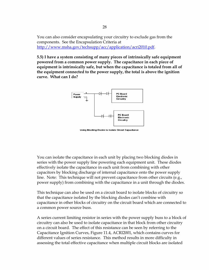
You can also consider encapsulating your circuitry to exclude gas from the components. See the Encapsulation Criteria at http://www.msha.gov/techsupp/acc/application/acri2010.pdf. 5.5) I have a system consisting of many pieces of intrinsically safe equipment powered from a common power supply. The capacitance in each piece of equipment is intrinsically safe, but when the capacitance is totaled from all of the equipment connected to the power supply, the total is above the ignition curve. What can I do?
You can isolate the capacitance in each unit by placing two blocking diodes in series with the power supply line powering each equipment unit. These diodes effectively isolate the capacitance in each unit from combining with other capacitors by blocking discharge of internal capacitance onto the power supply line. Note: This technique will not prevent capacitance from other circuits (e.g., power supply) from combining with the capacitance in a unit through the diodes.
This technique can also be used on a circuit board to isolate blocks of circuitry so that the capacitance isolated by the blocking diodes can’t combine with capacitance in other blocks of circuitry on the circuit board which are connected to a common power source buss.
A series current limiting resistor in series with the power supply buss to a block of circuitry can also be used to isolate capacitance in that block from other circuitry on a circuit board. The effect of this resistance can be seen by referring to the Capacitance Ignition Curves, Figure 11.4, ACRI2001, which contains curves for different values of series resistance. This method results in more difficulty in assessing the total effective capacitance when multiple circuit blocks are isolated
29
by resistors compared to the use of diode blocking.
5.6) I need to use a large value capacitor in my design that by itself results in an entry point well above the ignition curve when assumed charged to the full power supply voltage, under fault conditions. Under normal circuit operation, the capacitor only charges to a much lower safe value. What can I do to overcome this problem?
You can solve this problem by using two zener diodes connected in parallel across the capacitor with a zener voltage selected low enough to clamp the capacitor’s maximum charge voltage to a safe value according to the capacitance ignition curves, but above the normal operating voltage of the capacitor. The zener diodes should have adequate power dissipation ratings under fault conditions when the diodes are in the conduction mode to avoid device failure or their becoming a thermal ignition source. To determine adequacy, calculate the power dissipated by multiplying the maximum current flow through the zener diode, under fault conditions, times the zener voltage. The zener diode power dissipation rating should be greater than the calculated power dissipated. Printed circuit tracings should be configured such that the opening of a single trace does not disconnect both zener diodes from the capacitor.
5.7) I am using an inductive component and the inductance ignition curves indicate operation over the ignition curve with the DC current that can flow under fault conditions. What techniques can be used to allow safe use of this device?
A protective current limiting resistor can be placed in series with the inductive device to reduce current to a level that the inductance ignition curves indicate as safe. This method may not be suitable in situations where it is necessary to maintain a specific minimum voltage for proper operation of the inductive device such as for relays and solenoids. For these cases, two shunt diodes or zener diodes may be placed in parallel with the inductive device to serve as spark suppression devices in case the power lead to the inductive device is broken.
These diodes must be installed and rated per the requirements of ACRI2001, Section 8.6. It is important to locate the diodes as close to the inductor’s terminals as possible and to use separate circuit paths from each diode to the inductor terminals so that both diodes can’t become disconnected due to a single fault. It is important that each of the diodes have a forward current rating equal to the current that would flow if they failed in a short circuit mode. The use of three diodes in parallel instead of just two diodes would eliminate the need for them to meet any specific forward current ratings.
30
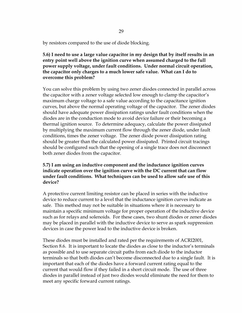
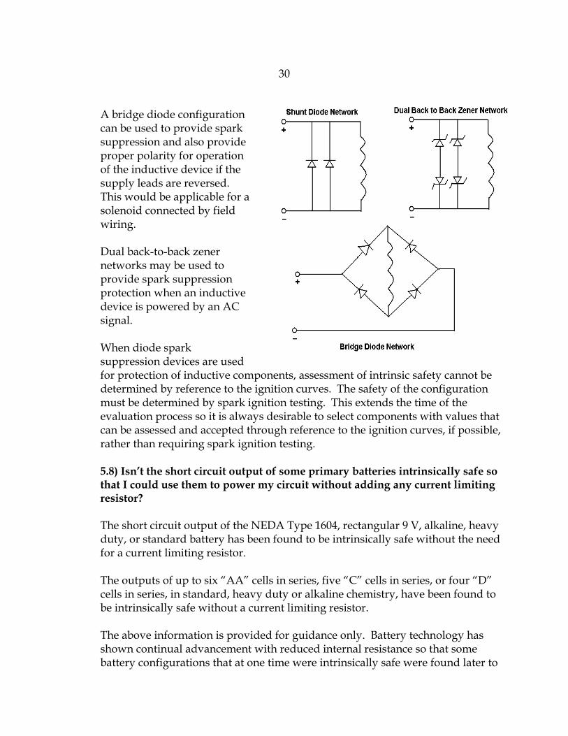
A bridge diode configuration can be used to provide spark suppression and also provide proper polarity for operation of the inductive device if the supply leads are reversed. This would be applicable for a solenoid connected by field wiring.
Dual back-to-back zener networks may be used to provide spark suppression protection when an inductive device is powered by an AC signal.
When diode spark suppression devices are used for protection of inductive components, assessment of intrinsic safety cannot be determined by reference to the ignition curves. The safety of the configuration must be determined by spark ignition testing. This extends the time of the evaluation process so it is always desirable to select components with values that can be assessed and accepted through reference to the ignition curves, if possible, rather than requiring spark ignition testing.
5.8) Isn’t the short circuit output of some primary batteries intrinsically safe so that I could use them to power my circuit without adding any current limiting resistor?
The short circuit output of the NEDA Type 1604, rectangular 9 V, alkaline, heavy duty, or standard battery has been found to be intrinsically safe without the need for a current limiting resistor.
The outputs of up to six “AA” cells in series, five “C” cells in series, or four “D” cells in series, in standard, heavy duty or alkaline chemistry, have been found to be intrinsically safe without a current limiting resistor.
The above information is provided for guidance only. Battery technology has shown continual advancement with reduced internal resistance so that some battery configurations that at one time were intrinsically safe were found later to
31
be unsafe. This is the reason that you are required to specify the specific manufacturer’s name and part numbers for the batteries you wish to be allowed for use with your design. MSHA will make a determination of the safety of your submitted battery configuration based on current tests of battery samples. 5.9) How can I avoid the delays associated with current limiting resistor testing and possible test failures?
Testing of a current limiting resistor to qualify it as a protective component may be avoided by specifying a wire-wound or metal film resistor that operates at no more than two-thirds its power rating under normal and fault conditions (See ACRI2001, Section 8.4).
5.10) How can I avoid resistor surface temperature tests and the delays associated with conducting the tests and with possible test failures?
In a circuit design, a number of low ohmic value resistors are typically identified for surface temperature testing to confirm that they do not pose a thermal ignition source for coal dust or methane-air gas mixtures under fault conditions. Since the test procedure requires testing of multiple samples of each ohmic value, and the test voltage slowly stepped up to the worst case value in small increments with stabilization time at each increment, the process can accumulate hours of test time. The stepping procedure is used to ensure the maximum temperature is measured before possible open-circuiting of the resistor occurs.
To avoid resistor surface temperature tests, specify the resistor ohmic values and power ratings such that, if a resistor is assumed faulted across the power supply buss powering the circuit, it operates within its power dissipation rating. The simple formula, P=E2/R, may be used for this calculation. For example, assume a 1,000 Ohm resistor with a 0.10 Watt dissipation rating in a circuit powered by a 9 Volt battery. When the resistor is assumed faulted across the battery, its power dissipation will be 92/1000=0.081 Watts. This condition is safe since the resistor is operating within its power dissipation rating. Using this design approach avoids the surface temperature test, fault analysis, and PC board spacing analysis that normally is involved in identifying potential thermal ignition sources. If this results in unreasonably high resistor dissipation ratings, a soldered-in fuse should be considered, located in series with the power supply buss powering the board circuitry, to reduce current to ease dissipation rating requirements.
Here is another tip for avoiding discrepancy letters and delays when surface temperature tests can’t be avoided and testing needs to be conducted on surface mount resistors. Do not submit loose surface mount samples for test since MSHA
32
can not conduct the test without the resistors mounted on a test board. Ten samples of each surface mount resistor value undergoing test must be submitted. The resistors should be mounted on a printed circuit board with two flying leads provided and connected to printed circuit tracings leading to each resistor to allow connection to the MSHA test fixture. The separation of the resistor and the flying leads by printed circuit tracings (1 to 2 inches long) prevents the leads from de-soldering from the board due to high resistor temperatures.