underground rainwater harvesting system · as a suitable alternative for places that have adequate...
TRANSCRIPT

Underground Rainwater Harvesting System
Stanford University Global Engineering Programs Summer Service Learning Program – Uganda 2016
Claret Zárate Buenrostro | Kate Gasparro | Mikhail Grant Haley Kong| Montana Marshall| Robert Pinkerton
2
Executive Summary This report presents the design process and construction guide for a reproducible underground rainwater harvesting (URWH) system that will increase a household’s access to clean water during the dry season, help generate savings for that family, and increase leisure time. Currently, about 44% of families in Uganda do not have ready access to clean water and about 53% of Ugandans travel more than 40 minutes to get water.1,2 In light of this clean-water shortage problem in Uganda, the SSLP team researched strategies for making rainwater harvesting (RWH) systems affordable for a majority of rural community members in Kabale, Uganda. After conducting a literature review and needs-finding process, the team determined that an URWH system invented by Twinamatsiko Alphonse of Go Organic Africa was the most ideal RWH system for rural households in Southern Uganda. The SSLP team then created innovations for the system and documented its construction to create an instruction manual. In this report, we begin by providing background information on Southern Uganda and on the URWH system invented by Go Organic Africa. Then, we provide the general methodology behind the design and construction of the system along with our innovations. The methodology of our design process is as follows: (1) perform initial surveys of households which possess the URWH system as well as households without the system; (2) identify potential points of improvement based on survey feedback; (3) select parts of system for re-design; (4) prototype re-designs; and (5) construct system with our innovations incorporated in order to determine construction considerations for the instruction manual and to produce a bill of quantities. Lastly, we present a detailed construction and user guide and recommendations for potential future steps. A submersible pump drives the URWH system and is capable of transporting water from an underground tank with a depth of 5 feet and volume of about 4900 litres. The system is covered by a walled structure that prevents accidents, water theft and contamination. This system, though intended to serve one household of six people, has the potential to serve multiple, depending on the rainfall frequency during the dry season. The total estimated cost of this system (including labor, transportation, safety measures, and materials) ranges from USD $150 to $360, depending on community contribution. There are many benefits that this RWH system can have for a given household. Firstly, providing clean water to a household will improve public health. Reliable, uncontaminated water reduces the spread of waterborne illnesses among both people and animals. The URWH system will also reduce the amount of effort and time people spend transporting water by hand. The RWH system also has community-wide economic benefits. With the water provided by the system, crops can be grown close to the household instead of being bought in town or elsewhere; this decreases the money spent on food and thus generates savings for households. Additionally, constructing the RWH system will require labor– both skilled and unskilled. This labor has historically been sourced from the surrounding rural community. Increased demand for labor creates jobs for local rural communities. Increased employment enables families to gain income.
1 http://ageconsearch.umn.edu/bitstream/135134/2/12-3Shively.Hao.pdf 2 Uganda Demographic and Health Survey 2011

3
Table of Contents
1. Introduction .......................................................................................................................................... 5 1.1 Scope of Project .............................................................................................................................................. 5 1.2 Outline of Report ............................................................................................................................................ 6
2. Background ............................................................................................................................................ 7 2.1 Overview of Climate in Southern Uganda.................................................................................................. 7 2.2 Water Situation in Southern Uganda .......................................................................................................... 8 2.3 Overview of URWH System .......................................................................................................................... 8
2.3.1 Guttering System ................................................................................................................................................... 9 2.3.2 Underground Tank .............................................................................................................................................. 10 2.3.3 Pump and Walled Structure ............................................................................................................................. 10 2.3.4 Projected Social Impact of URWH System ................................................................................................... 12
3. Innovation Process and Improvements .......................................................................................... 13 3.1 Analysis of System Before Innovations ................................................................................................... 13
3.1.1 Observations from Community Interviews ................................................................................................. 13 3.1.2 Conclusions Drawn from Community Interviews ...................................................................................... 15 3.1.3 Problem Statement ............................................................................................................................................. 15
3.2 Prototyping ................................................................................................................................................... 16 3.2.1 Prototype #1: Overflow Mechanism ............................................................................................................. 16 3.2.2 Prototype #2: First-Flush Mechanism, Low-Fidelity ................................................................................. 18 3.2.3 Prototype #3: First-Flush Mechanism, High-Fidelity ................................................................................ 19
3.3 Final Design ................................................................................................................................................... 22 3.3.1 Overflow Mechanism Design ........................................................................................................................... 22 3.3.2 First-Flush Mechanism Design ......................................................................................................................... 23
4. Instruction Manual ............................................................................................................................. 24 4.1 Introduction .................................................................................................................................................. 25
4.1.1 Overview of Underground Rainwater Harvesting System ...................................................................... 25 4.1.2 Important Terms .................................................................................................................................................. 26 4.1.3 Components of an URWH System .................................................................................................................. 27 4.1.4 Figures Detailing Structure of URWH System ............................................................................................. 28 4.1.5 Overview of Materials and Tools .................................................................................................................... 30
4.2 Construction Manual .................................................................................................................................. 31 4.2.1 Construction of Pump ........................................................................................................................................ 31 4.2.3 Construction of Underground Tank ............................................................................................................... 38
4.3 User’s Guide ................................................................................................................................................. 56 4.3.1 Usage ....................................................................................................................................................................... 56 4.3.2 System Maintenance .......................................................................................................................................... 57 4.3.3 Periodic Maintenance ........................................................................................................................................ 58
5. Conclusion ........................................................................................................................................... 59 Acknowledgements ................................................................................................................................ 61 Works Cited ............................................................................................................................................. 64
4
Appendix .................................................................................................................................................. 65 A1. Images to aid in Construction of URWH System ................................................................................... 65 A2. Materials and Tools for Construction ...................................................................................................... 67 A3. Cost Analysis ................................................................................................................................................ 73
Table A3. Cost Analysis Spreadsheet ........................................................................................................................ 74 A4. Risk Analysis ................................................................................................................................................. 80 A5. Community Interviews ............................................................................................................................... 83
A.5.1 All Interview Questions: .................................................................................................................................... 83 A.5.2 Recorded Interview Questions ........................................................................................................................ 85 A.5.3 Interview Responses ........................................................................................................................................... 85
A6. Slideshow Presentation ............................................................................................................................. 89

5
1. Introduction This report presents the design process and construction guide for a reproducible, underground rainwater harvesting (URWH) system that will increase a rural household’s access to clean water, allow for more free time, and provide an additional means of increasing savings. The term ‘rainwater harvesting’ (or RWH) is usually defined as the immediate collection of rainwater off the surfaces upon which it has fallen directly; this definition excludes rainwater that runs off land watersheds into streams, rivers, lakes, etc.3 Rain can provide some of the cleanest naturally-occurring water and is available in many regions throughout the world. Furthermore, if properly stored, the collection of clean water via RWH can be especially important during dry seasons when rainfall is scarce. As a result, where there is no surface water, or where groundwater access is unfeasible due to hard ground or poor sanitation conditions, the collection of rainwater can serve as a suitable alternative for places that have adequate rainfall within a given year. Twinamatsiko Alphonse of Go Organic Africa originally invented the URWH system described in this report, and Stanford Engineering’s SSLP Uganda Team of 2016 created innovations for the system. The system was initially proposed as a solution for the lack of access to clean water in rural areas of Kabale, Southern Uganda. However, the system is meant to be reproducible across Uganda and other countries where scalability would depend on location, climate, and application. Already, the system has been reproduced beyond Kabale District, into two of the other three districts that comprise the southern Kigezi region of Uganda – Kisoro District and Rukungiri District.4 Since 2014, under the initiative and oversight of Go Organic Africa, approximately 400 of these URWH systems have been installed. The construction of these systems was made possible through a combination of private individual donors and larger NGO donation efforts (e.g. from Caritas International). It is the anticipation that, with the provision of the construction manual and user guide in this report, the influence and implementation of the RWH system will be more widespread, even beyond the borders of Uganda.
1.1 Scope of Project Our project focused on the application of a RWH system for a rural household of six or less people in Southern Uganda. We focused on rural households because access to clean water is a constant struggle for many rural families in Southern Uganda. Water from the municipal system is provided by the National Water and Sewer Corporation. However, many rural households are not connected to the municipal system, and household members must spend much of the day collecting water from relatively distant springs or wells; the time required for this collecting can be as much as 4 to 6 hours per day. Despite the fact that it rains significantly for over half of the year in the rural areas of Uganda, there is often still a need to collect water at a spring or well. The difficulties of access to water throughout the year are further complicated by the fact that a significant number of the springs from which water is collected are not maintained under sanitary conditions. As a result, about 44% of families in Uganda currently do not have access to safe water.5 This lack of access to
3 WaterAid. Rainwater harvesting Technical Brief 4 Only Kanungu District does not have this URWH system. 5 http://ageconsearch.umn.edu/bitstream/135134/2/12-3Shively.Hao.pdf
6
clean water creates a major public health concern. Additionally, the need to collect water can reduce people’s quality of life, for the time used to collect water could be otherwise used to generate income and perform other domestic activities. In light of this clean-water shortage problem in Southern Uganda, the SSLP team sought to look at making rainwater catchment systems affordable for a majority of rural community members; Alphonse’s URWH system was determined to be most ideal. The storage capacity for this URWH system is designed to last for 3 months, which is the duration of the dry season that occurs in the middle of the year in Uganda. Other rainwater harvesting systems tend to be around $500 and are thus not economically accessible for many rural households in Uganda. The RWH system explained in this report, however, offers a more cost-effective and accessible model to supply water to rural households in locations that may be far from surface water sources or municipal water connectivity. Additionally, through the provision of a construction manual and user guide for the RWH system, it is the aspiration of Go Organic Africa, SSLP and KIHEFO that this system will be locally sustainable and reproducible in the areas where it is implemented.
1.2 Outline of Report
The report begins by briefly introducing the topics of climate and water use in Southern Uganda. It then briefly describes the key components of the system and the advantages that each component contributes to the overall efficiency of the system. The report then outlines the innovation process conducted by SSLP for improving the URWH system. Finally, the report presents the instruction manual that delineates the construction and proper operation and maintenance of the URWH system. A list of anticipated materials for the construction of the URWH system is available in the construction manual. All costs are tabulated in Appendix A2, where a full cost analysis is outlined. Photos of the construction of the URWH system, as well as a rudimentary risk analysis, are also provided in the Appendix section of this report.

7
2. Background
2.1 Overview of Climate in Southern Uganda The southern tip of Uganda consists of several highland districts, which includes Kabale. The geography creates a microclimate with considerably cooler temperatures and increased rainfall relative to the rest of Uganda and sub-Saharan Africa. A summary of the climate data for Kabale is provided below6:
Elevation: 1,219 - 2,347 meters
Temperature: 12°C (night) – 25°C (daytime)
Humidity: 90-100% (morning); 42-75% (afternoon)
Rainfall: 20 mm (dry season) - 150 mm (wet season) The districts of Southern Uganda experience a two-season climate with wet seasons occurring from March to May and from September to December. The rest of the year experiences a dry season with light rainfall from January to March, and little to no rainfall from mid-May to the end of August.7
Season Duration
Dry (light rain) January - March
Wet (Heavy rainfall) March - May
Dry (little to no rainfall) May - September
Wet (Heavy rainfall) September - November
Table 1. Summary of Seasons in Southern Uganda During Kabale’s rainy season, average monthly precipitation in the region is approximately 100 mm and can be as much as 150 mm during the months of April and May (see Figure 1 below).6 As a result, there is considerable scope for the collection and storage of rainwater when it falls in Uganda, before huge losses occur due to evaporation and transpiration and before the rainwater becomes contaminated.
Figure 1. Average Precipitation in Kabale, Uganda 6
6 https://weather-and-climate.com/average-monthly-Rainfall-Temperature-Sunshine,Kabale,Uganda 7 ‘Groundwater Pumping & Storage System: Summer Service Learning Program – Uganda 2015’. SSLP 2015

8
2.2 Water Situation in Southern Uganda
On average, 6% of the households in Uganda have water on their premises. In 2011, 28% of urban households were likely to have a water source in their house or yard compared to 2% of rural households. According to the latest Uganda demographic and health survey, for households that do not have water on their premises, more than half (54%) travel 30 minutes or more to fetch their drinking water: 17% people in urban areas and 62% people in rural areas travel this length of time. It is also important to note that 87% of the population lived in rural areas in 2010.8 Thus, about 53% of Ugandans travel more than 40 minutes to get water. This chore of fetching water often falls disproportionately on female members of the household, causing additional strain on household activities.9 The most common technology options for rural water supplies are protected springs, boreholes, and protected wells and gravity flow distribution system; these technologies are considered ‘improved water sources’.6 Unsafe sources include rivers, lakes, and unprotected wells. If water needs to be fetched from a source that is not immediately accessible to the household, it may get contaminated during its transportation or storage even though the water is obtained from an improved source. According to the Poverty Eradication Action Plan (PEAP), water use in rural areas ranges between 12 and 14 litres per person and day (l/p/d). In urban towns and centers with a population of more than 5,000 people, the PEAP estimates an average of less than 17 l/p/d.10 Thus, with an average daily use of 13 l/p/d, a rural household of six people would need approximate 7000 litres of water to last them through the mid-year dry season. The system invented by Go Organic Africa (GOA) can hold 4900 litres of water and has a surface area of 180 m2; even if water does not rain for the entire dry season, a household of six can still, on average, contain water for 70% of the dry season with this given storage capacity. Therefore, one can see that, with a household that has less six people or that uses less than 13 l/p/d, the storage capacity of the GOA URWH System can sustain a household for the entire dry season. With an average monthly rainfall of 125 mm/month during the wet season, the GOA URWH system can be completely filled in as little as 7 days with rainwater.
2.3 Overview of URWH System The system is mainly comprised of a guttering system, underground storage tank, pump, and walled structure (see images below). The innovations made to the system include the automation of the “first flush” and “overflow” mechanisms. The first-flush mechanism refers to the collection or diversion of the first run-off that tends to be dirty as the first rainfall drives off and collects the dirt and debris on the roof of household. First-flush mechanism prevents accumulated bird droppings, leaves, twigs, dust, contaminants and debris from entering the storage tank. The overflow mechanism refers to the prevention of water from going above the surface level of the tank, which would result in the deterioration of the walled structure (which, in this case, is made of wood and mud). Details on how these systems were improved upon will be explained in detail in the
8 World Health Organization; UNICEF. Joint Monitoring Program 9 Uganda Demographic and Health Survey 2011 10 Republic of Uganda; Ministry of Finance; Planning and Economic Development. "Poverty Eradication Action Plan (2004/5-2007/8)"

9
Innovations/Improvements section of this report. Below is an overview of the key components of the system.
URWH system built in Kengoma village First-flush mechanism of URWH system
2.3.1 Guttering System The rainwater is collected from the roof of a household, and gutters placed around the eaves of the building funnel the collected rainwater from the roof toward the down-pipe(s). The downspouts discharge the rainwater into the storage tank. Low-cost guttering can be made from metal sheeting (e.g. iron sheets of 32-gauge thickness) hammered to form a “U” shape, and suspended from the roof by wire or metal, as shown in the images below. With regards to the provision of clean water for domestic use, RWH systems where rainwater is collected from tiled or corrugated metal roofs are ideal. Rock catchments or roofs made of leaves or thatch have a shorter lifespan and risk contaminating the run-off; this is especially the case for rock catchments that are not protected from access by animals and children. Additionally, rain and termites can destroy thatched roofs. Hence, having a roofing and guttering system made of metal is more durable and allows for little to no contamination of the rainwater collected by the system.
Installation of downspout on to gutter Gutter suspended from edge of roof
10
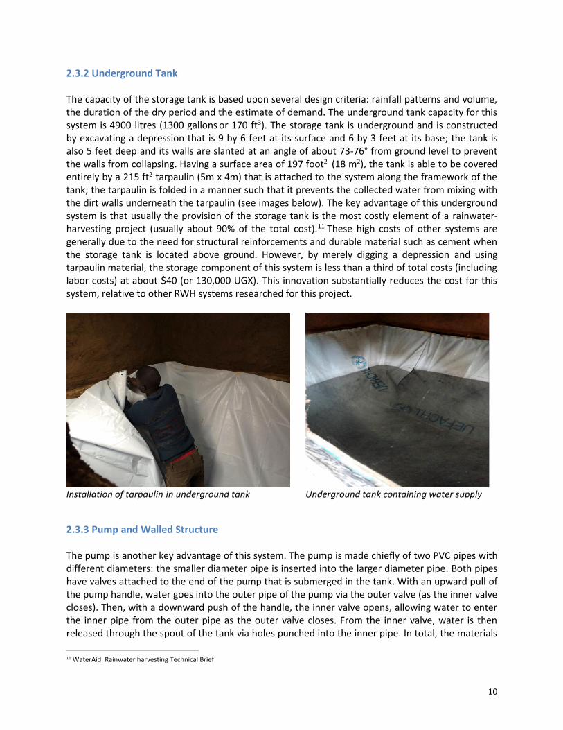
2.3.2 Underground Tank The capacity of the storage tank is based upon several design criteria: rainfall patterns and volume, the duration of the dry period and the estimate of demand. The underground tank capacity for this system is 4900 litres (1300 gallons or 170 ft3). The storage tank is underground and is constructed by excavating a depression that is 9 by 6 feet at its surface and 6 by 3 feet at its base; the tank is also 5 feet deep and its walls are slanted at an angle of about 73-76° from ground level to prevent the walls from collapsing. Having a surface area of 197 foot2 (18 m2), the tank is able to be covered entirely by a 215 ft2 tarpaulin (5m x 4m) that is attached to the system along the framework of the tank; the tarpaulin is folded in a manner such that it prevents the collected water from mixing with the dirt walls underneath the tarpaulin (see images below). The key advantage of this underground system is that usually the provision of the storage tank is the most costly element of a rainwater-harvesting project (usually about 90% of the total cost).11 These high costs of other systems are generally due to the need for structural reinforcements and durable material such as cement when the storage tank is located above ground. However, by merely digging a depression and using tarpaulin material, the storage component of this system is less than a third of total costs (including labor costs) at about $40 (or 130,000 UGX). This innovation substantially reduces the cost for this system, relative to other RWH systems researched for this project.
Installation of tarpaulin in underground tank Underground tank containing water supply
2.3.3 Pump and Walled Structure The pump is another key advantage of this system. The pump is made chiefly of two PVC pipes with different diameters: the smaller diameter pipe is inserted into the larger diameter pipe. Both pipes have valves attached to the end of the pump that is submerged in the tank. With an upward pull of the pump handle, water goes into the outer pipe of the pump via the outer valve (as the inner valve closes). Then, with a downward push of the handle, the inner valve opens, allowing water to enter the inner pipe from the outer pipe as the outer valve closes. From the inner valve, water is then released through the spout of the tank via holes punched into the inner pipe. In total, the materials
11 WaterAid. Rainwater harvesting Technical Brief

11
and manufacturing of the pump costs less than 15% of the cost of the system at approximately $36 (or 120,000 UGX). The pump is preferable over other methods of water collecting such as the use of pulleys or buckets. This is because of its ease of use (push/pull motion), consideration of safety (minimizes risk of falling in), and promotion of sanitation (prevents contamination that can be associated with manual collection). Moreover, the pump helps in the preservation of the tarpaulin. The bottom part of the pump is suspended in the middle of the tank and the top part is accessed for external use as the top part of the pump is installed on one of the walls of the walled structure; no part of the pump comes into contact with the tarpaulin. On the other hand, a collecting device such as a bucket would risk damaging the tarpaulin as it may disturb the tarpaulin when immersed in the tank.
T-joint of pump before installation Pump after installation
The walled structure is composed of a wooden framework that is packed with mud for stability and reinforcement. It is also comprised of a roof made of iron sheets. These components of the walled structure prevent contamination of the water from external sources such as polluted runoff. The walled structure is equipped with a locked door, which prevents children from accessing the inside of the system (a safety hazard) and also prevents water theft. Significant delays in the construction of the system include waiting three days for mud of the walled structure to dry. Also, if construction does not occur during the dry season and it begins raining during construction, further delay of the drying process can occur. The URWH system is very convenient in terms of cost and labor. In total, the system costs as little as $150 with significant community contribution, or as much as $360 with no community contribution (see Cost Analysis section in Appendix for explanation). The average time period for construction is around a week (half of this time being for mud-drying), and as few as 2 skilled laborers and 2-3 unskilled laborers are required.

12
2.3.4 Projected Social Impact of URWH System There are many benefits that this URWH system can have for a given household. Firstly, providing clean water to a household will improve public health. Reliable, uncontaminated water reduces the spread of waterborne illnesses among both people and animals. The URWH system will also reduce the amount of effort and time people spend transporting water by hand. This will allow for increased productivity and improved quality of life for the members of that household; if women and children spend less time collecting water, they can be empowered, as women can spend more time on their livelihood and children can spend more time in school or on their chores. The water supply can also assist in domestic work, as it can be used for watering small gardens and feeding the household animals. There are also economic benefits to the URWH system. Due to water shortages, some rural households are usually unable to grow crops on their property; they would have to go to town or travel long distances in order to buy costly food products. However, with the URWH system providing a close-by water source, rural households can grow crops in small gardens on site. This allows household to save money on food which is important in a country where as much as 63% of household expenditure can go towards food costs.12 Also, though selling of water is not encouraged by Go Organic Africa, if the system is properly managed and rainfall is sufficient, households possessing the system can sell water to community members as a means of generating income. It was discovered during community surveys that households with the system were already selling water to neighbours at 500-1000 UGX per 20 litres of water. The URWH system also has community-wide economic benefits. Constructing the URWH system will require labor – both skilled and unskilled. Unskilled labor would be needed to cut and gather wood, create mud, and excavate the depression, among other tasks. Skilled labor (such as a mason) are needed for such tasks as ensuring that measurements are being taken correctly and that components of the system are structurally sound. This labor has historically been sourced from the surrounding rural community when past URWH systems were built by Go Organic Africa. Increased demand for labor creates jobs for local rural communities. Increased employment enables families to gain income (a skilled laborer and unskilled laborer can earn about 90,000 UGX and 45,000 UGX respectively for three days of work on the system). Therefore, higher incomes for these families will allow widespread rural development by providing additional income that can be directed toward education for children, investment in crops and livestock, and access to health services.
12 Uganda Demographic and Health Survey 2011

13
3. Innovation Process and Improvements
3.1 Analysis of System Before Innovations The original underground rainwater harvesting (URWH) system was designed by Twinamatsiko Alphonse and Go Organic Africa. Since the system was first designed in 2014, more than 400 of these systems have been installed in three districts of the Kigezi region of Uganda (Kabale, Kisoro and Rukungiri), throughout a 42-mile radius from Kabale. To assess both the state of rainwater harvesting in rural communities and the functionality of the URWH system in the households that have it installed, interviews were conducted with four households that had the system. These households are located in Kagoye village, a rural community near Kabale Town. The set of questions created, outlined in Appendix A4, were used to guide the conversations with the households and to gather information about various aspects of water access: underground storage, water use, available materials, water quality, culture, gender roles, etc. Table A.4.3 in Appendix 4 summarizes the responses from the critical questions that households with the URWH system were asked.
Interviewing resident of Kagoye village Observing one of the existing URWH systems
3.1.1 Observations from Community Interviews From the community responses, the following observations and inferences were made: Key Benefits of the System:
1. RWH systems are preferred by rural households, as opposed to other water sources such as springs that may contain unknown sources of water contamination. There is a preference for RWH systems because the quality of water collected by RWH is primarily determined by the catchment surface, which is usually clean if the roofing is made of metal sheets and the first flush is properly executed.
2. The URWH system allows for more time for every member of the family to work, generate
income, and complete necessary household chores.

14
3. The URWH system allows for a larger average daily use of water for the household (from about 10-13 l/d/p13 to 18-20 l/d/p). This increased average daily use results in better hygiene and, often times, greater food production.
4. All interviewed households reported that they would be willing to pay a price that was
either greater than or equal to the current cost of the URWH system. This shows that the URWH system is affordable for the rural households interviewed and even has an impact more valuable than its construction value.
Key Drawbacks of the System:
1. Currently, the amount of water required before the first-flush water is clean is decided upon using visual observation. This monitoring is not ideal as using visual observation to determine the cleanliness of water is prone to error.
2. Rare storms during the dry season have the ability to refill the tank. However, these rare opportunities for refill are often missed if the storm occurs when the family is not present and so cannot move the gutter from the first-flush position to the inlet hole (e.g. the family may be asleep in the middle of the night or away from home for an extended period while it is raining).
3. Overflow can easily happen when a storm occurs overnight or when the family is away from the household; avoiding overflow of the tank requires close monitoring of tank levels during the wet season. Proper monitoring minimizes the risk of overflow and the resulting structural damage that occurs. However, this monitoring is difficult to do, given the several other tasks that a household has to perform throughout the day.
4. All four households that were interviewed shared or sold the water from their system with
neighbours and other members of the community. This sharing and selling of water resulted in their supply running out before the end of the dry season. This circumstance emphasizes the importance of capturing storm rainfall during the dry season, as some URWH systems supply more than one household (even though it was initially designed for use by only one household) and these systems will run out of water if they are not refilled by storm rainfall during the dry season.
5. The URWH systems of the households interviewed have only been installed for one year and
therefore have only experienced one wet season and one dry season. Mainly due to the short time for which these systems have existed, no structural problems with the system were reported. Longer-term impacts of the system on the household and the durability of the system were thus not able to gathered from community surveys. Longer-term impacts and system durability need to be continuously monitored and assessed in future field projects. Continuous monitoring will allow for proper conclusions to be made on the efficiency and sustainability of the systems and for any structural issues of the system to be properly studied.
13 l/d/p – litres per day per person
15
3.1.2 Conclusions Drawn from Community Interviews Based on the above observations, the following conclusions were drawn about the original system:
1. This particular URWH system (designed by Alphonse and Go Organic Africa) has proven to be very well received and successful in rural communities in the Kigezi region. The system’s success is due to the fact that it: introduces a cleaner source of water; utilizes the heavy rainfall that is common in Uganda during the rainy season; allows for water supply, even in the 3-month dry season; eliminates the extensive walk required in some villages to obtain water at the closest spring; is affordable to most rural households; improves hygiene and nutrition; increases household incomes. As a result of these several benefits, it was concluded that this URWH system is the most appropriate rainwater harvesting option for this region. Hence, the system should be improved upon and its construction should be properly documented to help increase the number of household with the system.
2. The first-flush and overflow mechanisms should be automated in order to decrease the
extent to which the system is monitored, maximize water catchment (especially in the dry season), and minimize damage to the structure caused by overflow. Furthermore, an automated first-flush mechanism would use a fixed volume known to be sufficient for first flush. This fixed volume would be based on scientific research and literature. Hence, a URWH system with the automated first-flush mechanism could produce water that is more thoroughly clean for drinking and household uses than water collected using visual observation of the first flush.
3.1.3 Problem Statement Based on the above observations and subsequent conclusions drawn, the following problem statement guided the innovation process for the remainder of the project: Problem Statement - to increase the accessibility of Alphonse’s underground rainwater harvesting system by creating an instruction manual and to also improve the system’s usability by automating the first-flush and overflow mechanisms. Following the community survey process and formulation of problem statement, the prototyping of the automated mechanisms was the next step in the innovation process. Following the prototyping of the automated mechanisms, a version of the URWH system with the automated mechanisms was constructed on the premises of a household located in Kengoma village in Kagarama Parish14. Based on the construction of this system, the construction process was documented and the instruction manual created for distribution purposes.
14 Kagarama Parish is located in Kabale District

16
3.2 Prototyping After conducting the interviews in the local community, it was deemed necessary to prototype automated overflow and first-flush mechanisms and test their functionality and efficacy.
3.2.1 Prototype #1: Overflow Mechanism Objective: To analyze the variables that influence the overflow rate. Construction: A clear, plastic water bottle was used to emulate the underground tank, as it was watertight and provided visual transparency that allowed the water level in the bottle to be easily measured. A heated nail was used to puncture the cap of the water bottle; this cap was then flipped upside down so that water would accumulate inside the cap instead of rolling right off the top when the inlet was being modeled. The same heated nail was also used to create a hole on the side of the water bottle (located at about half of the water bottle height, above the bottom). This ensured that there were two holes of equal size:
Inlet hole = hole in the cap of the water bottle Outflow hole = hole in the side of the water bottle
For testing, three different attachment scenarios were designed for the outflow: 1) No attachment – the outflow hole on the side of the water bottle 2) Full straw attachment – 1 inch plastic straw inserted into outflow hole 3) Half straw attachment – 1 inch plastic straw cut in half to resemble a gutter and inserted
into the outflow hole The attachments remained perpendicular to the water bottle; this was achieved by resting the attachment on a nail lying horizontally across a ceramic cup. The nail provided both height and support, as it prevented the attachment from bowing from the weight of the water inside the attachment. The ceramic cup was also used to capture and recycle the testing water. When necessary during testing conditions, plastic mesh was manually held over the attachment.
Water bottle with bored cap on top Water bottle with full straw attachment perpendicular
17
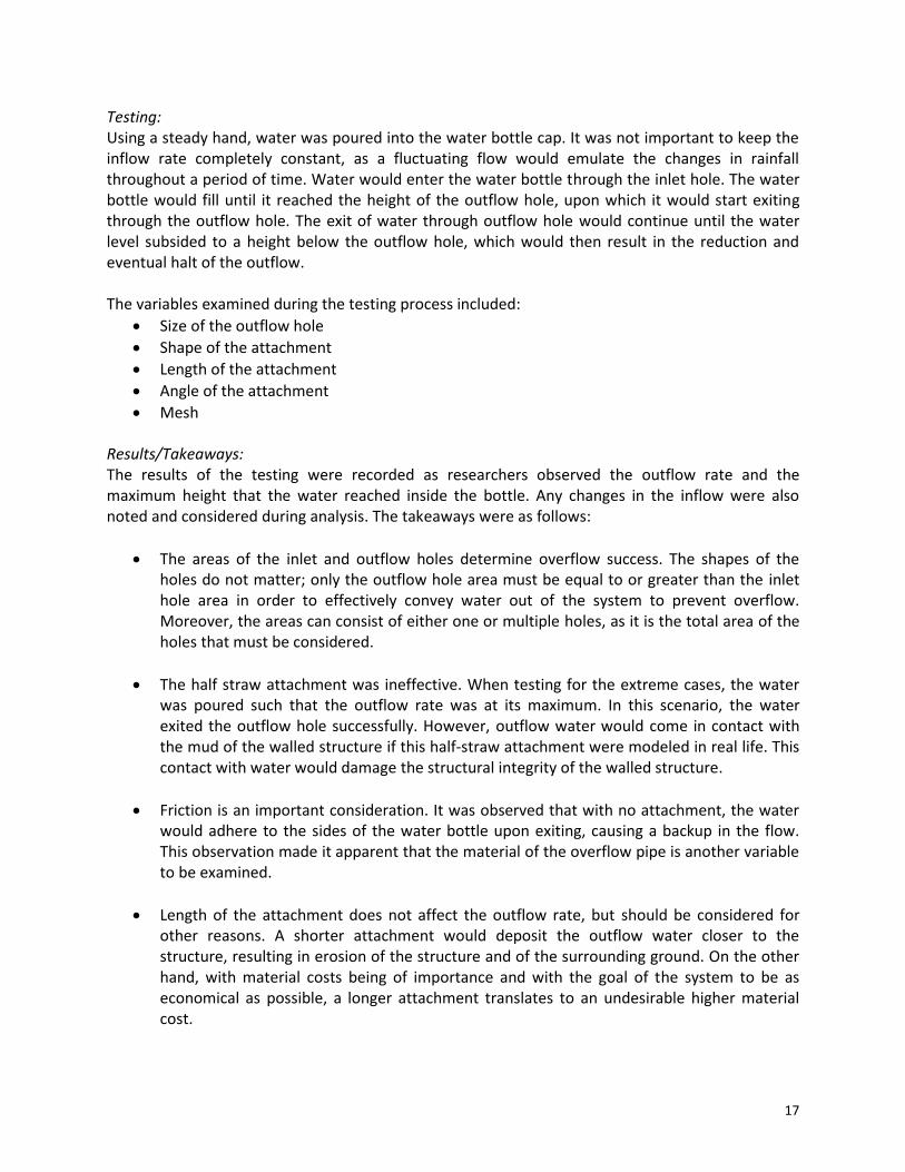
Testing: Using a steady hand, water was poured into the water bottle cap. It was not important to keep the inflow rate completely constant, as a fluctuating flow would emulate the changes in rainfall throughout a period of time. Water would enter the water bottle through the inlet hole. The water bottle would fill until it reached the height of the outflow hole, upon which it would start exiting through the outflow hole. The exit of water through outflow hole would continue until the water level subsided to a height below the outflow hole, which would then result in the reduction and eventual halt of the outflow. The variables examined during the testing process included:
Size of the outflow hole
Shape of the attachment
Length of the attachment
Angle of the attachment
Mesh Results/Takeaways: The results of the testing were recorded as researchers observed the outflow rate and the maximum height that the water reached inside the bottle. Any changes in the inflow were also noted and considered during analysis. The takeaways were as follows:
The areas of the inlet and outflow holes determine overflow success. The shapes of the holes do not matter; only the outflow hole area must be equal to or greater than the inlet hole area in order to effectively convey water out of the system to prevent overflow. Moreover, the areas can consist of either one or multiple holes, as it is the total area of the holes that must be considered.
The half straw attachment was ineffective. When testing for the extreme cases, the water was poured such that the outflow rate was at its maximum. In this scenario, the water exited the outflow hole successfully. However, outflow water would come in contact with the mud of the walled structure if this half-straw attachment were modeled in real life. This contact with water would damage the structural integrity of the walled structure.
Friction is an important consideration. It was observed that with no attachment, the water would adhere to the sides of the water bottle upon exiting, causing a backup in the flow. This observation made it apparent that the material of the overflow pipe is another variable to be examined.
Length of the attachment does not affect the outflow rate, but should be considered for other reasons. A shorter attachment would deposit the outflow water closer to the structure, resulting in erosion of the structure and of the surrounding ground. On the other hand, with material costs being of importance and with the goal of the system to be as economical as possible, a longer attachment translates to an undesirable higher material cost.
18
The angle of the attachment must be at 90° or more (angled downward from the structure wall). Once the straw was lifted such that it was no longer perpendicular, the flow of the water slowed considerably. At 90° and more, the outflow could reach its maximum rate. From these observations, it was concluded that it was necessary to place the outflow pipe on the downhill side of the structure to allow for the appropriate angle of the attachment as well as proper conveyance away from the structure.
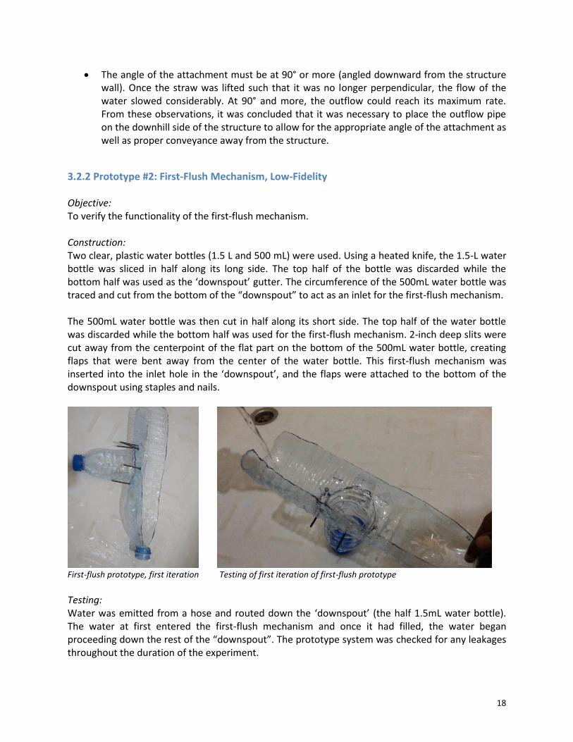
3.2.2 Prototype #2: First-Flush Mechanism, Low-Fidelity Objective: To verify the functionality of the first-flush mechanism. Construction: Two clear, plastic water bottles (1.5 L and 500 mL) were used. Using a heated knife, the 1.5-L water bottle was sliced in half along its long side. The top half of the bottle was discarded while the bottom half was used as the ‘downspout’ gutter. The circumference of the 500mL water bottle was traced and cut from the bottom of the “downspout” to act as an inlet for the first-flush mechanism. The 500mL water bottle was then cut in half along its short side. The top half of the water bottle was discarded while the bottom half was used for the first-flush mechanism. 2-inch deep slits were cut away from the centerpoint of the flat part on the bottom of the 500mL water bottle, creating flaps that were bent away from the center of the water bottle. This first-flush mechanism was inserted into the inlet hole in the ‘downspout’, and the flaps were attached to the bottom of the downspout using staples and nails.
First-flush prototype, first iteration Testing of first iteration of first-flush prototype
Testing: Water was emitted from a hose and routed down the ‘downspout’ (the half 1.5mL water bottle). The water at first entered the first-flush mechanism and once it had filled, the water began proceeding down the rest of the “downspout”. The prototype system was checked for any leakages throughout the duration of the experiment.

19
Results/Takeaways: This prototype served as a proof-of-concept for the first-flush mechanism found in other literature. The majority of the water entered the first-flush mechanism, but some of the water bypassed the mechanism by passing through the holes near the flaps or going through the gap between the downspout and the mechanism because the diameter of the first-flush inlet was marginally smaller than the size of the downspout. There were also leakages in the system. The prototype provided some good insights for the next iteration prototype:
Better sealant was crucial. The staples and nails were sufficient in holding the flaps down, but it was not a watertight seal and water was able to travel underneath the flaps. For the mechanism to work, the sealant must be very effective such that no water leaks from the first-flush mechanism and the sealant must be adhesive to both materials being joined.
Water did not skip over the first-flush mechanism. It was a concern that, with a steeper angle of the downspout, the water would not enter the first-flush mechanism. However, with the testing of the angles of the downspout, it was observed that the level of adhesion to the downspout was greater than expected and that in order for the water to jump over the first-flush mechanism, the downspout must be at an extreme and unrealistic angle.
3.2.3 Prototype #3: First-Flush Mechanism, High-Fidelity Objective: To use local materials to create a ready-to-deploy first-flush mechanism. Construction – Stage 1: Materials were purchased in Kabale hardware stores. A metal sheet was bent into a “gutter” by folding both ends, allowing the ends to stand upright. The circumference of a 3-inch diameter PVC pipe was traced in two different locations on the bottom of the gutter. On the gutter, two openings were cut to test for the most effective design:
1) Hole with downward-folding wedges: 1.5-inch incisions were cut away from the centerpoint of the traced circle, creating slices. The slices were cut using a nail, knife, and hammer. These slices were bent downwards from the “gutter” until they formed a 90-degree angle with the flat bottom of the gutter.
2) Traditional hole: The second traced circle was cut out along the traced line, and the metal circle was removed.
Hole with folded wedges Tracing of traditional hole

20
Testing – Stage 1: While holding the ‘gutter’ at a slant, water was poured along the gutter via a watering can and observed as it entered each of the two holes. Then, the gutter was tilted the opposite direction and the same analysis occurred. Results/Takeaways – Stage 1: For the hole with downward-folding wedges, the water more easily entered as it was funneled down the downspout and wedges. For the traditional hole, the water was getting caught on the elevated metal burrs created from the construction. This led to the decision that the hole with downward-folding wedges would be used for stage 2 of prototype #3 because it created a flush surface with the gutter. Construction – Stage 2: One foot of the 3-inch diameter PVC pipe was cut, and its circumference was traced on the largest side of a jerrycan. Using a heated knife, the traced circle on the jerrycan was cut out. The PVC pipe was inserted into the jerrycan at the bottom and the inlet hole at the top, making sure that the slices were on the inside of the PVC pipe. At first, silicone sealant and PVC cement were utilized as bonding agents; however, once both failed to hold the materials together, epoxy was used as the sealant. Epoxy was applied liberally to the interfaces between the PVC pipe and the gutter and between the PVC pipe and the jerrycan. These joints were held in place for 10 minutes until the epoxy solidified at the interfaces. Testing – Stage 2 Tilting the prototype system such that the hole with downward-folding wedges was at the end of a downward slant, water was poured down the ‘downspout’ until the jerrycan filled and the PVC was partially filled. The sealant between the jerrycan and the PVC was checked for leakages. Once the epoxy was verified to be functioning as expected, additional water was poured down the downspout until the water filled the PVC and started to overflow. The sealant between the downspout and the jerrycan was then visually checked for leaks. The system was left overnight under a covered area and then checked for any unwanted leakages the next morning.
Stage 2 of First-flush prototype Stage-2 Testing of first-flush mechanism
21
Results/Takeaways
There were no observations of leakages until the overnight portion of the testing. When checked the following day, the ground immediately around the jerrycan had darkened, showing that there was some slow water leakage throughout the night. Both the functionality and the construction process had some key outcomes:
The hole in the gutter should span the entire width of the gutter. When pouring the water down the gutter, some of the water tended to divert along the spaces between the PVC inlet hole and the gutter walls, instead of into the hole. If increasing the size of the hole (i.e. using a larger diameter PVC pipe) is not a viable option, then walls should be brought closer to direct the water into the hole.
Other tools should be used to cut the metal. Utilizing the nail and hammer did not create smooth edges in the metal and was labor intensive, and the jagged surface served as a deterrent for the flow of the water.
Epoxy should be further researched. Epoxy proved to be extremely strong and effective at sealing connections between materials such as plastic and metal (unlike the silicone sealant and PVC cement), but there was no explicit data as to its lifespan, toxicity, or accessibility. These were points for further research, but the current design strategy would be to apply the epoxy in a way that minimized the amount of water it contacted (see construction manual for details).
Sealant area must be cleaned before applying the sealant. The sealant was lumpier and more difficult to apply when there were areas with dust.
Standing water is a phenomenon that needs to be considered. It became evident that standing water could be of concern for the users since there was no way of effectively covering the water in the PVC pipe and water could be sitting in the jerrycan for long periods of time if the user does not empty it. This should be something that is considered more during the development of the user guide that would highlight specific operations guidelines to avoid this issue.
PVC pipe should be inserted only a few centimeters into the jerrycan hole. During the testing, the PVC pipe was inserted into the jerrycan by an inch; water would stop filling jerrycan and enter into the PVC pipe once the water reached the bottom level of the PVC pipe in the jerrycan. This caused water to flow down the gutter prematurely before the jerrycan was fully filled. To decrease the chances of this phenomenon, the PVC pipe would have to be inserted to a level just barely beneath the epoxy seal connecting the PVC pipe to the jerrycan.

22
3.3 Final Design With the three prototypes providing valuable insight into the design considerations for the overflow and the first-flush mechanisms, the final version of the automated overflow and first-flush mechanisms were designed and their construction included in the URWH system used for this report as well as in the instruction manual for the construction and use of the system. Their characteristics and features are explained below.
3.3.1 Overflow Mechanism Design The automated overflow mechanism has the following characteristics and features:
Retrofit Design – Designed to be easily installed on both new systems and pre-existing systems. The only requirements are that a hole must be carved out at the base of the downhill side of the URWH walled structure and there must be adequate materials for the outflow pipe. Carving the hole can be done with a machete, and the materials required can be acquired from leftovers of the system’s original construction.
Outflow Hole – Carved out using a machete. This carving would require cutting through some of the mud and/or wooden poles of the wall structure. The total area of the outflow hole is greater than or equal to the area of the inlet hole.
Tarpaulin – Funnels into the outflow hole. Inside the tank, the part of the tarpaulin (or ‘tarp’) that is closest to the overflow mechanism will be nailed into the pipe and tank framework to ensure that no water can go behind the tarp and wear away at the underground tank walls.
Outflow Pipe – Constructed from two leftover pieces of iron sheet. Both pieces should be hammered to resemble gutters, and one should be placed on top of the other. This creates a makeshift pipe; the overlap between the two sheets will help to keep the outflow water contained such that the outflow does not erode away the wall structure as it exits the system. The outflow pipe should be made to be at least 10 inches in length in order to deposit outflow at a reasonable distance from the wall structure.
Mesh – Constructed from metal wiring, which may be leftover from construction of the inlet hole. Mesh is wrapped around the mouth of the outflow pipe to prevent rodents from entering in the pipe. A piece of binding wire or any other fastener is wrapped around the mesh and the circumference of the pipe to hold the mesh in place.
Concrete Support – If the overflow device is not being retroactively fitted, the concrete support can be constructed from concrete left over from construction. The concrete, mixed with small rocks, is used to fill in the gaps between the structure and the outflow device. This support impedes any outside pests from entering the URWH tank.
23
3.3.2 First-Flush Mechanism Design The automated first-flush mechanism has the following characteristics and features:
Retrofit Design – Designed to be easily installed on both new systems and pre-existing systems. The mechanism requires extra materials (all of which are locally accessible) but does not necessitate the deconstruction of the entire URWH system; only the downspout would need modification.
Downspout Hole – Brings the water to the PVC pipe. Using a machete, a hole with downward-folding wedges can be created in the downspout and the slices can be folded downwards. This configuration will help direct the water into the PVC pipe and provides additional surface area for the epoxy. Because the first-flush water would not be used for consumption, it was not considered necessary to have an overlying mesh; the resulting additional installation, extra materials, and required further maintenance were also considered as deterrents against using an overlying mesh.
PVC Pipe – Links the downspout hole to the jerrycan. The pipe should be large enough in diameter such that it occupies the majority of the downspout base. The first-flush pipe for the system considered in this report was 3 inches in diameter, similar to the width of the downspout (which was about 3.5 inches).
Jerrycan – Holds the first-flush water. Research recommends 35 L of first-flush water for every 100 m2 of roof to ensure adequate water quality. 15 As a result, depending on the area of the roof, the quantity and sizes of the jerrycan(s) will vary between systems. To prevent standing water, the lid of the jerrycan can be unscrewed to empty some of the water. For a complete drain of the jerrycan, the downspout must be removed from the gutter system and tilted so that the jerrycan can fully empty.
Epoxy – Provides seals between materials. There is an epoxy seal from metal to PVC and PVC to jerrycan. It provides a watertight seal and should be used on the outsides of each connection to ensure that the epoxy does not come into contact with the runoff water.
15 Yaziz, M., Gunting, H., Sapari, N. and Ghazali, A. 1989 “Variations in rainwater quality from roof catchments.” Water Research, 23(6), 761-765.

24
4. Instruction Manual
Table of Contents
4.1 Introduction .................................................................................................................................................. 25
4.1.1 Overview of Underground Rainwater Harvesting System ...................................................................... 25
4.1.2 Important Terms .................................................................................................................................................. 26
4.1.3 Components of an URWH System .................................................................................................................. 27
4.1.4 Figures Detailing Structure of URWH System ............................................................................................. 28
4.1.5 Overview of Materials and Tools .................................................................................................................... 30
4.2 Construction Manual .................................................................................................................................. 31
4.2.1 Construction of Pump ........................................................................................................................................ 31
4.2.3 Construction of Underground Tank ............................................................................................................... 38
4.3 User’s Guide ................................................................................................................................................. 56
4.3.1 Usage ....................................................................................................................................................................... 56
4.3.2 System Maintenance .......................................................................................................................................... 57
4.3.3 Periodic Maintenance ........................................................................................................................................ 58

25
4.1 Introduction An underground rainwater harvesting (URWH) system is a system that passively collects water from metal rooftops and stores it in an underground tank. A roofed structure surrounds the tank and houses a plastic pump that is used to withdraw the water from the tank. The collected water can be used for household uses (washing, watering, etc) and, after it is boiled, for drinking.
4.1.1 Overview of Underground Rainwater Harvesting System Why is the system underground and not aboveground? Underground systems are more cost-effective and easier to clean. A 5000-L black cistern by itself would cost over USD $500, which is much more costly than this entire URWH system (See Cost Analysis Appendix). Furthermore, the cisterns are more difficult to clean, as the narrow opening on top hinders anyone or anything from attempting to remove dirt and debris from the inside of the tank. On the other hand, the URWH allows a person to enter the tank and clean it easily. How much water does this system hold? This system is estimated to hold approximately 4900 litres. This amount of water can last a family of six for 3 months, assuming that the family uses an average of 2 to 3 jerrycans (40 L) a day. Can I make the tank larger? The size of the tarpaulin limits the size of the tank. The tarpaulin used in this manual is 4m x 5m, and it can store approximately 4900 litres. If the tank size is increased in any direction, the tarpaulin will not be able to fully cover the base of the underground tank. How do I withdraw water from the system? The plastic PVC pump is used for withdrawing water. The user will need to pump it about 3-6 times before the water will start coming out, and this water can be captured in a jerrycan or a bucket. Because the bottom of the pump will not touch the bottom of the tank, the pump will not be able to reach all of the water inside the tank. This residual water can be removed manually by entering through the door of the structure and removing the water with the bucket. How is the quality of the water? In this system, the quality of the water is compromised by the dirt and debris that accumulates on sections of the system where water makes contact: roofing, gutters, downspout, and tarpaulin. The cleaner these sections, the better the quality of water will be. As opposed to other water sources, like wells where the underground contamination is unknown, any source of quality conditions with the water from the URWH can be more easily identified. Assuming that water will be extracted from the system nearly every day, providing routine water movement, there will be no standing water. Can I drink the water? Water from the tank is drinkable only if it is boiled beforehand. Unboiled water from the system is fit for household activities like washing, watering the garden, etc. Water from the first-flush mechanism should not be consumed as it contains many more particulates and contaminants than
26
the water from the tank. Therefore, this water should only be used for activities where humans are not the consumers, like watering the garden and feeding the animals. How long does it take to build this URWH system? Assuming that all resources and materials are acquired on time and there are no weather delays, the URWH system should take a week to construct. To expedite the process, communities can build multiple tanks at a time so that by the end of their construction period, they have more than one URWH system. How do I maintain my tank? Please see User Guide.
4.1.2 Important Terms
First Flush The rainwater that flows off the household roof immediately after a dry season. During the dry season, the roof of the house accumulates significant amounts of dirt and debris. In the first rain, if a first-flush mechanism is not installed or the downspout moved away from inlet hole, this dirt and debris could be washed into the underground tank, thus contaminating the water supply. Overflow The water that surpasses the height of the tank. Once the water rises to a level above the height of the underground tank, the water can begin damaging the surrounding structure. The overflowing water can weaken the dirt structure and contaminate the water supply within the tank.16 Abbreviations cm centimetre m metre m2 square metre ft foot ft2 square foot L litre ‘ foot ‘‘ inch
Measurement Conversions Length/Distance 1 foot = 0.3 metre 1 metre = 3.28 feet 1 inch = 2.54 cm 1 cm = 0.39 inch Volume 1 gallon = 3.78 litres 1 litre = 0.26 gallon Area 1 m2 = 10.76 ft2 1 ft2 = 0.9 m2
16 Dirt from the mud of walled structure can be washed into the tank if water level surpasses height of the tank
27
4.1.3 Components of an URWH System Please see Figures 1 to 4 in section 4.1.4 for a visual representation of each numbered component.
Part Sub System Function Design Specification
1 Gutter Catches the rainwater after it flows off the roof.
Slanted slightly towards the URWH system such that water will flow down the gutter to the roof of the URWH system.
2 Downspout Routes the rainwater from the gutter to the inlet hole.
Can be freestanding or supported. The lengths of the downspouts and the designs of the supporting structures will vary because each household will have different locations of their gutters and tanks.
3 First-Flush Mechanism
Prevents first-flush water from entering the tank. While the jerrycan still has space for water, the first-flush water will flow into the jerrycan instead of inlet hole.
The attached jerrycan will be oriented such that the lid faces downhill, so once the jerrycan is drained, the water will flow off the roof of the URWH.
4 Roof Protects the water in the underground tank.
Slanted such that any water that is not in the downspout is routed down the corrugated sheet metal and off the roof.
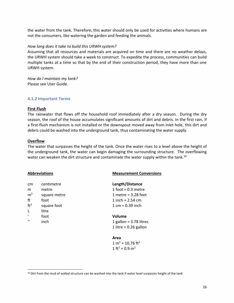
5 Inlet Hole Provides an opening and basic filtration such that the water can enter the tank.
The area of the inlet hole is smaller than the outflow hole; contains bucket and mesh for filtration.
6 Walled Structure
Provides security from contamination, water theft, and animals.
Surrounds the underground tank.
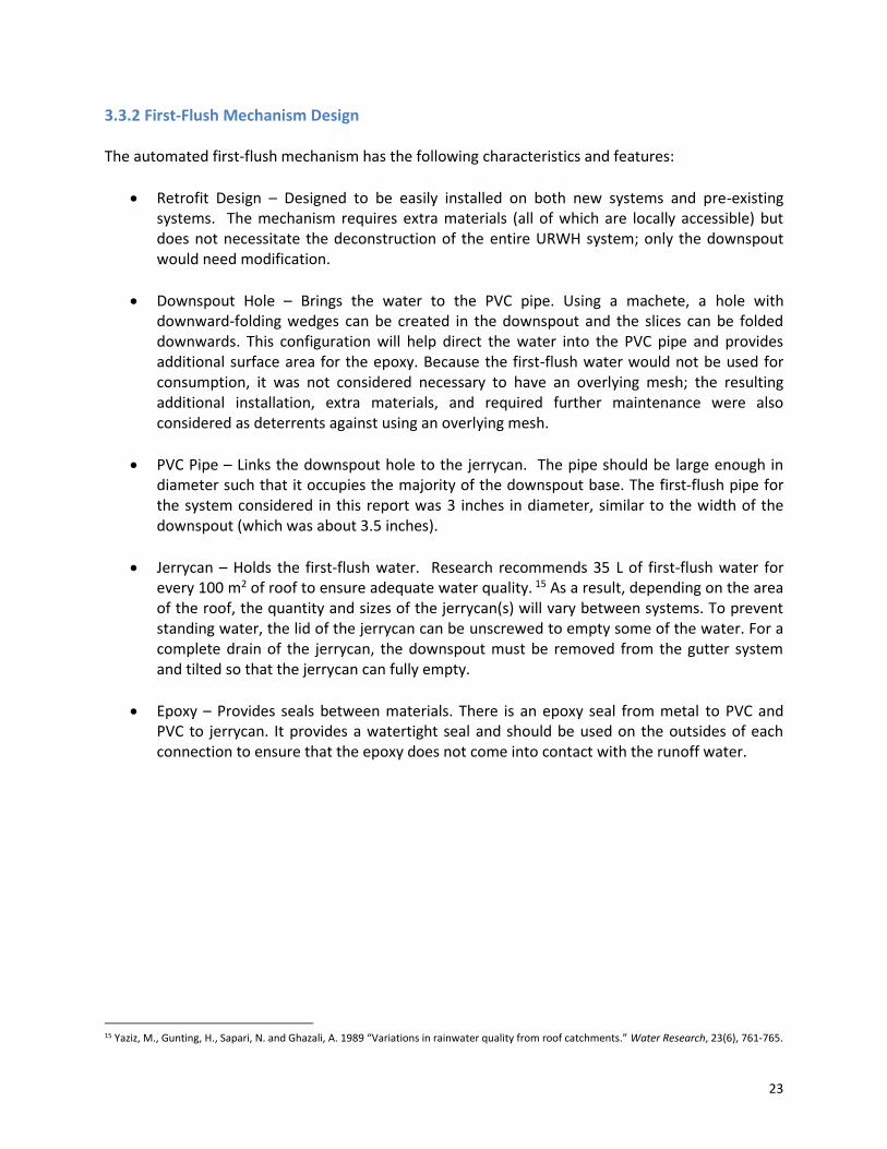
7 Tank Holds the harvested rainwater.
Located far enough away from the house to avoid blocking paths but close enough for the downspout to reach.
8 Pump Withdraws water from the tank. Located at about the height of a 20-L jerrycan from the ground.
9 Doorway Allows for more thorough cleaning of the tank.
Large enough such that a human can comfortably enter the tank.
10 Overflow Hole
Prevents the tank from reaching above its maximum volume.
Has a total area that is greater than or equal to inlet hole.
Table 1. Name and Function of each Numbered Component in Figure 1-4

28
4.1.4 Figures Detailing Structure of URWH System
Figure 1
Figure 2
29
Figure 3
Figure 4

30
4.1.5 Overview of Materials and Tools The material measurements and quantities, as well as tools necessary for each stage of construction are listed in the beginning of each section. All materials were found in Kabale, Uganda. It is recommended that the materials for all stages of the construction be gathered prior to the start of construction so as to minimize the number of purchasing trips and the chance of construction delays. A table of required materials and tools can be found in the appendix of this document. ** Note about Materials ** Some material requirements may not be appropriate for your region. For example, for the structure, the instructions assume that you have the same soil type and wood as what is commonly available in Kabale, Uganda. However, if these materials are not locally found, substitutions for more locally sourced materials may be necessary.
31
4.2 Construction Manual
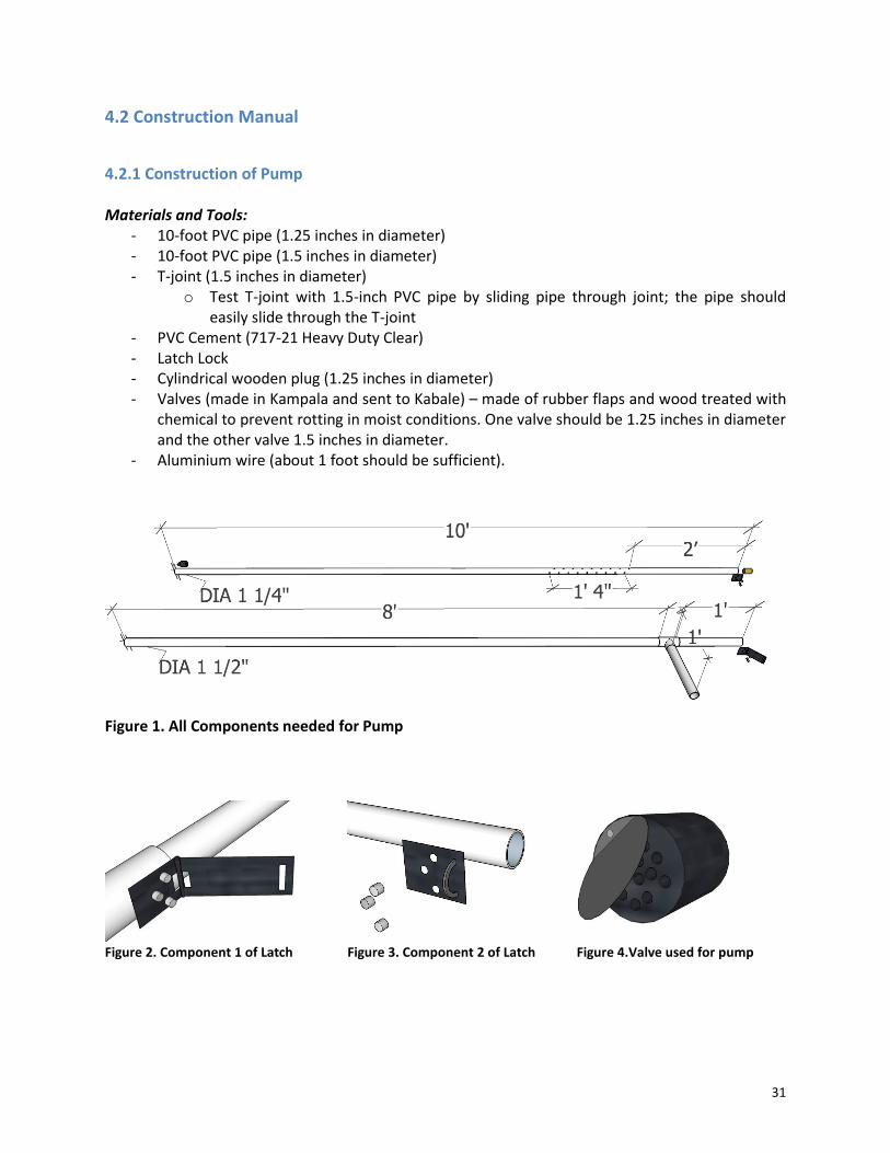
4.2.1 Construction of Pump Materials and Tools:
- 10-foot PVC pipe (1.25 inches in diameter) - 10-foot PVC pipe (1.5 inches in diameter) - T-joint (1.5 inches in diameter)
o Test T-joint with 1.5-inch PVC pipe by sliding pipe through joint; the pipe should easily slide through the T-joint
- PVC Cement (717-21 Heavy Duty Clear) - Latch Lock - Cylindrical wooden plug (1.25 inches in diameter) - Valves (made in Kampala and sent to Kabale) – made of rubber flaps and wood treated with
chemical to prevent rotting in moist conditions. One valve should be 1.25 inches in diameter and the other valve 1.5 inches in diameter.
- Aluminium wire (about 1 foot should be sufficient).
Figure 1. All Components needed for Pump
Figure 2. Component 1 of Latch Figure 3. Component 2 of Latch Figure 4.Valve used for pump
32
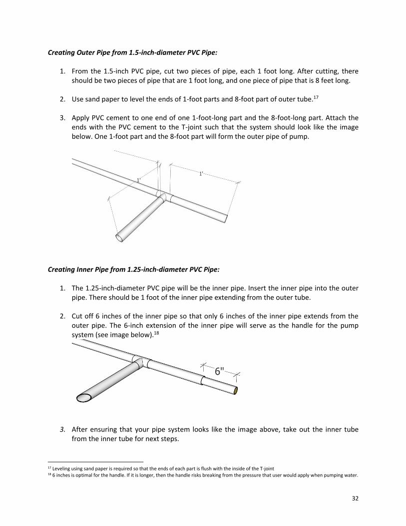
Creating Outer Pipe from 1.5-inch-diameter PVC Pipe:
1. From the 1.5-inch PVC pipe, cut two pieces of pipe, each 1 foot long. After cutting, there should be two pieces of pipe that are 1 foot long, and one piece of pipe that is 8 feet long.
2. Use sand paper to level the ends of 1-foot parts and 8-foot part of outer tube.17
3. Apply PVC cement to one end of one 1-foot-long part and the 8-foot-long part. Attach the ends with the PVC cement to the T-joint such that the system should look like the image below. One 1-foot part and the 8-foot part will form the outer pipe of pump.
Creating Inner Pipe from 1.25-inch-diameter PVC Pipe:
1. The 1.25-inch-diameter PVC pipe will be the inner pipe. Insert the inner pipe into the outer pipe. There should be 1 foot of the inner pipe extending from the outer tube.
2. Cut off 6 inches of the inner pipe so that only 6 inches of the inner pipe extends from the
outer pipe. The 6-inch extension of the inner pipe will serve as the handle for the pump system (see image below).18
3. After ensuring that your pipe system looks like the image above, take out the inner tube
from the inner tube for next steps.
17 Leveling using sand paper is required so that the ends of each part is flush with the inside of the T-joint 18 6 inches is optimal for the handle. If it is longer, then the handle risks breaking from the pressure that user would apply when pumping water.

33
Attaching Latch to the PVC Pipes: Part 1 (Attaching Component 1 of latch to outer pipe without blocking inner pipe movement):
1. Drill holes on one end of the 1-foot part of outer piping using a drill or heated nail. The holes should match the pattern of holes on Component 1 of the latch; use the latch as a guide to where the holes should be drilled.
2. Use sand paper to level the holes on 1-foot part of outer tube. 3. Hammer down aluminium wire to create nails of 1-cm diameter. Cut three 1-cm pieces from
the aluminium wire and use hammer to create sharp end, (see Image 1 in Appendix A1). 4. Placing the latch against the outer tube, slightly hammer down the sides of Component 1
against the pipe so as to create a curved shape for Component 1 to match the shape of the outer pipe.

34
5. Insert the head of a second hammer into the end of outer pipe with the drilled holes; this hammer head will act as support for hammering and ensure that the aluminium nails flatten on the inside of the outer tube when hammered in. With the shank (i.e. sharp end of nail) directed toward the pipe, hammer Component 1 of latch on to outer pipe using. Keep the hammer in the pipe so that both sides of aluminium nails are flattened upon hammering. The image below should help you see how Component 1 should be hammered on to the 1-foot part of outer pipe.
6. Check that the aluminium nails inserted are not obstructing the motion of the pump by re-
inserting the inner pipe into the outer pipe and ensuring that it moves freely without jamming/obstruction. The outer pipe should look like the image below upon completion.
Part 2 (Attaching Component 2 of latch to inner pipe):
1. Cut off excess part of inner tube that extends from outer pipe so that end of inner tube aligns with Component 1 when it is extended. Pipe handle of inner tube should only be as long as the latch arm (i.e. about 9.5 cm / 3.75 inches). The inner pipe that extends out of outer pipe should no longer be 6 inches.
2. Placing Component 2 of latch against the inner tube, slightly hammer down the sides of
Component 2 against the pipe so as to create a curved shape for the lock that matches the shape of the inner pipe.

35
3. Insert a piece of cylindrical wooden plug (1.25 inches in diameter and 3-3.5 inches long) into the extending end of the inner tube.
4. Using 3.5-cm/1.5-inch nails that are 4 mm in diameter, hammer Component 2 onto the inner pipe as shown in the figure below. The nails will be inserted into the cylindrical wooden plug placed at the end of the inside of inner tube.
5. Level the wooden plug with sand paper to get wood and PVC aligned with the lock. The
latch should look like the images below.
Creating holes in inner pipe (holes will allow for water to be released at the T-junction of the pump):
1. Create holes starting 60 cm from the top of the inner tube19 (i.e. the side of the tube that has Component 2). Use a heated nail to drill a set of holes within a 40-cm range. Each drill should be about 5 cm apart. There should be 9 sets of holes. Drill all the way through the piping so that one drill creates two holes across from each other in the pipe.
19 60 cm allows holes to be below the T-joint outlet for water and allows enough water to be collected in the inside of tank while not permitting water to spill from the top of the pump (i.e. if holes are more than 60 cm from the top of inner tube, then less water will be collected per pump. If holes are less than 60 cm form the top of the inner tube, then this risks water spewing from the top of the pump instead of at the outlet)

36
2. Create a second set of holes such that the holes alternate and create a zigzag pattern (see image below).20 About 28 to 36 holes should be created in total.21
3. Remove burrs (i.e. extra pieces of PVC) stuck to holes after drilling.22 The inner pipe should look like the image below.
Creating and Placing the Valves:
1. Valves are made from rubber flaps and two cylindrical pieces of wood with holes drilled into them (see Figure 4 at beginning of Section 4.2.1). The rubber flaps are made from circular, flat pieces of rubber and are attached to the cylindrical pieces by a nail. If cylindrical pieces are made of wood, they should be treated with a chemical to prevent rotting that would occur upon exposure to water.
a. Insert the 1.5-inch (outside) valve into the outer pipe 2 cm in from the bottom of the
pipe. The rubber flaps should face the inside of the pipes (see Image 2 of Appendix A1).
b. Use heat and manually form the pipe around the plug. Close the end of the pipe and
reduce the circumference of the pipe above the valve as well as where the valve is located so that the valve fits snug into the pipes.
c. If the components of latch are not aligned after the outside valve has been installed,
cut off another inch or so (2-2.5 cm) off of the bottom of the inner pipe until both components of the latch are aligned.
20 Alternating holes all around the circumference of inner pipe allows for water to come out at any direction when inner pipe is lifted out during pumping. 21 Try not exceeding 40 holes. Too many holes will decrease the pressure needed inside pump to collect an optimal amount of water per pumping action. 22 Using sandpaper in this step is not recommended as it could reduce the size of the pipe

37
d. Insert the 1.25-inch (inside) valve into the inner pipe 2 cm in from the bottom of the inner pipe. The rubber flaps should face the inside of the pipes.
e. Repeat part b for inner valve.
Creating the Outlet:
1. Create a U-shape on the 1-foot part extending from T-joint with hacksaw for easier pouring
and less spillage. The U-shape should be about 1.5 inches in length as shown in the image below.
2. Smooth the edges of outlet with 60-grade sand paper. Last Steps:
1. Test pump with a bucket of water.
Image of how final pump should ultimately look

38
4.2.3 Construction of Underground Tank Digging Depression and Creating Tank Framework: Materials and Tools:
- shovels - hoe - pick - machete - measuring tape - pieces of wood about 3-4 inches in diameter (Pine, Eucalyptus, Cyprus, Grevillea)23
Instructions: 1. Level the ground area where URWH system will be located.
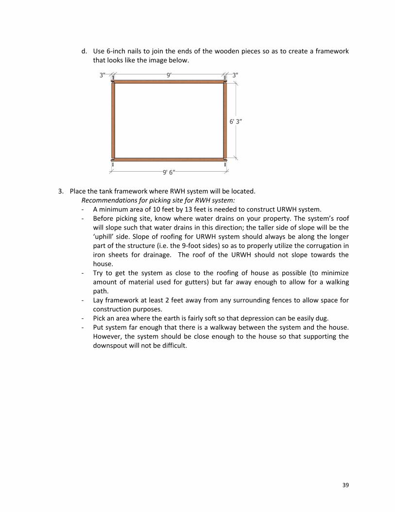
2. Create 9- by 6-foot framework for tank with pieces of wood.
a. Cut two pieces of wood 9 feet-6 inches in length (extra 6 inches are needed for
joints/corners of framework).
b. Cut two pieces of wood 6 feet in length.
c. Create notches at the ends of the wood pieces that are 9 feet 4 inches, as shown in the image below. Notch should be 3 inches wide.
23 A framework made of all Pine or Cyprus is ideal, but if Pine or Cyprus is not readily available then eucalyptus is also good (ideally from a hilly area instead of a swampy area). Grevillea is a soft wood and, though least ideal of these four types of wood, can also be used.
39
d. Use 6-inch nails to join the ends of the wooden pieces so as to create a framework that looks like the image below.
3. Place the tank framework where RWH system will be located. Recommendations for picking site for RWH system: - A minimum area of 10 feet by 13 feet is needed to construct URWH system. - Before picking site, know where water drains on your property. The system’s roof
will slope such that water drains in this direction; the taller side of slope will be the ‘uphill’ side. Slope of roofing for URWH system should always be along the longer part of the structure (i.e. the 9-foot sides) so as to properly utilize the corrugation in iron sheets for drainage. The roof of the URWH should not slope towards the house.
- Try to get the system as close to the roofing of house as possible (to minimize amount of material used for gutters) but far away enough to allow for a walking path.
- Lay framework at least 2 feet away from any surrounding fences to allow space for construction purposes.
- Pick an area where the earth is fairly soft so that depression can be easily dug. - Put system far enough that there is a walkway between the system and the house.
However, the system should be close enough to the house so that supporting the downspout will not be difficult.

40
4. Measure 2 feet diagonally from each corner of the framework to draw an interior rectangular area (6 by 3 feet in area) that is 6 feet by 3 feet at the center of the framework.
5. Dig a hole 6 feet by 3 feet wide and 5 feet deep at the center of the framework.
6. Create four sloped walls that start at the framework and meet the bottom of the 5-foot deep depression. When depression has been completely dug, it should resemble the images shown below.
Creating Framework for the Structure:24 Materials and Tools needed:
- wooden poles - nails (3.5 inches)
Instructions: 1. Dig four holes at the corners of the tank (outside of the wooden framework); holes should
be 1-foot deep and 8 inches in diameter.
24 Framework for the structure will be along the outside of the tank framework.
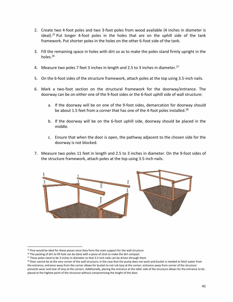
41
2. Create two 4-foot poles and two 3-foot poles from wood available (4 inches in diameter is ideal).25 Put longer 4-foot poles in the holes that are on the uphill side of the tank framework. Put shorter poles in the holes on the other 6-foot side of the tank.
3. Fill the remaining space in holes with dirt so as to make the poles stand firmly upright in the
holes.26
4. Measure two poles 7 feet 3 inches in length and 2.5 to 3 inches in diameter.27
5. On the 6-foot sides of the structure framework, attach poles at the top using 3.5-inch nails.
6. Mark a two-foot section on the structural framework for the doorway/entrance. The doorway can be on either one of the 9-foot sides or the 6-foot uphill side of wall structure:
a. If the doorway will be on one of the 9-foot sides, demarcation for doorway should be about 1.5 feet from a corner that has one of the 4-foot poles installed.28
b. If the doorway will be on the 6-foot uphill side, doorway should be placed in the middle.
c. Ensure that when the door is open, the pathway adjacent to the chosen side for the
doorway is not blocked.
7. Measure two poles 11 feet in length and 2.5 to 3 inches in diameter. On the 9-foot sides of the structure framework, attach poles at the top using 3.5-inch nails.
25 Pine would be ideal for these pieces since they form the main support for the wall structure 26 The packing of dirt to fill hole can be done with a piece of stick to make the dirt compact 27 These poles need to be 3 inches in diameter so that 3.5-inch nails can be driven through them 28 Door cannot be at the very corner of the wall structure; in the case that the pump does not work and bucket is needed to fetch water from the entrance, entrance away from the corner allows for bucket to not rub tarp at the corner; entrance away from corner of the structure prevents wear-and-tear of tarp at the corners. Additionally, placing the entrance at the taller side of the structure allows for the entrance to be placed at the highest point of the structure without compromising the height of the door.
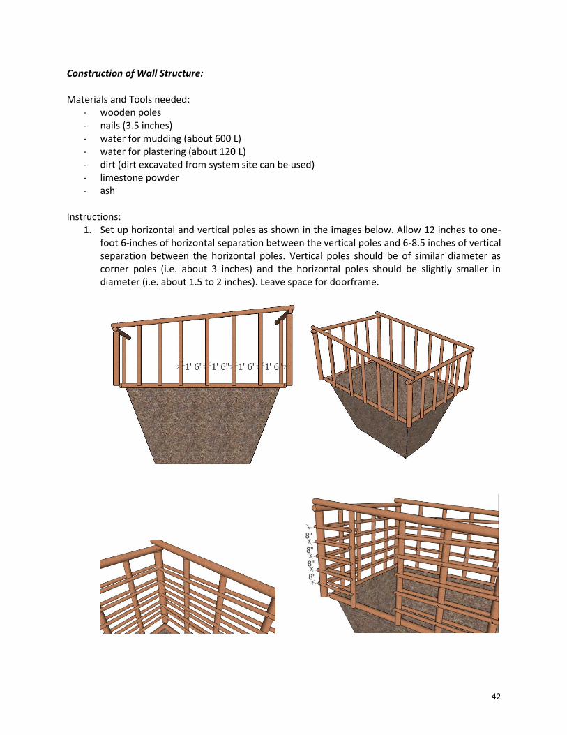
42
Construction of Wall Structure: Materials and Tools needed:
- wooden poles - nails (3.5 inches) - water for mudding (about 600 L) - water for plastering (about 120 L) - dirt (dirt excavated from system site can be used) - limestone powder - ash
Instructions:
1. Set up horizontal and vertical poles as shown in the images below. Allow 12 inches to one-foot 6-inches of horizontal separation between the vertical poles and 6-8.5 inches of vertical separation between the horizontal poles. Vertical poles should be of similar diameter as corner poles (i.e. about 3 inches) and the horizontal poles should be slightly smaller in diameter (i.e. about 1.5 to 2 inches). Leave space for doorframe.

43
2. Create mud by mixing 600 L of water with dirt.
3. Pack the wall structure with mud both in the inside spaces and along the exterior of the structure. Upon completion of packing, all wood of structure should be covered with mud.
4. Allow the structure to dry for a period of three days. After three days have passed, plaster structure with a mixture of limestone powder, ash and water. Limestone-to-ash ratio should be 5:2. About 10 basins of limestone and 4 basins of ash are needed along with 120 L of water.
Installing Door: Materials and Tools needed:
- doorframe - hammer - 6-inch nails - sticks/poles - mud - latch and lock
Instructions:
1. Install shutter so that door swings downhill with gravity. Hammer in the shutter with 6-inch nails into the wood supports of the wall structure.
2. Insert sticks/poles in the remaining gaps between door and structure. Fill gaps with mud.
3. Install lock and latch on to doorframe. Wait a full 24 hours before installing the lock on to
the door. Installing before 24 hours could result in disrupting the setting of the concrete used for the pump platform that will be built later. Door should lock like image below.
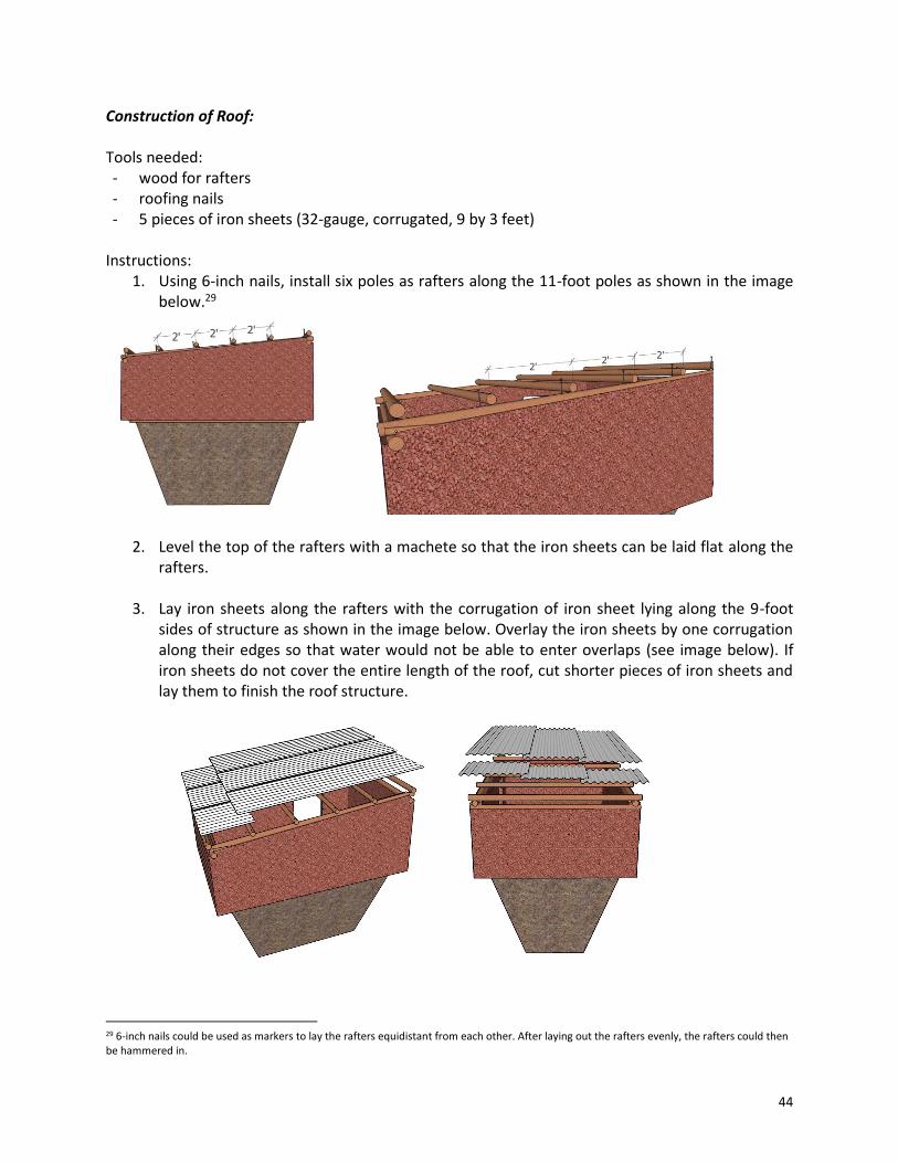
44
Construction of Roof: Tools needed: - wood for rafters - roofing nails - 5 pieces of iron sheets (32-gauge, corrugated, 9 by 3 feet)
Instructions:
1. Using 6-inch nails, install six poles as rafters along the 11-foot poles as shown in the image below.29
2. Level the top of the rafters with a machete so that the iron sheets can be laid flat along the rafters.
3. Lay iron sheets along the rafters with the corrugation of iron sheet lying along the 9-foot
sides of structure as shown in the image below. Overlay the iron sheets by one corrugation along their edges so that water would not be able to enter overlaps (see image below). If iron sheets do not cover the entire length of the roof, cut shorter pieces of iron sheets and lay them to finish the roof structure.
29 6-inch nails could be used as markers to lay the rafters equidistant from each other. After laying out the rafters evenly, the rafters could then be hammered in.

45
4. Hammer down the iron sheets with roofing nails. Hammer in 6-inch nails along the rafters
and on the overlaps so that iron sheets are attached to each other and to the structure via the rafters. Ensure to hammer the overlaps against a rafter.
Construction of Gutters and Downspout: Materials and Tools needed:
- Nails - Binding wire - Iron sheet - Payan metal - Hammer
Instructions:
1. Split remaining iron sheet into pieces that are about 9.25 inches in width against the direction of the corrugations.
2. Hammer down corrugation of iron sheet (see Image 3 in Appendix A1) so as to create a gutter shape.
3. Use payan metal (or binding wire) to attach gutter along roof edge of household.
a. Payan metal pieces should be about 22 inches in length and 5 ft apart along edge of roof.
b. Slope gutter such that water flows towards the URWH system.
c. Hammer gutter along rafter of roof with 3.5-inch nails (about 1 nail per 3.5 feet).

46
d. Use roofing nails to hammer payan metal around gutters (see image below). Put nail into payan metal before hammering on to roof so as to not hammer down and bend corrugation of roof.
4. Install the downspout(s) at the end of the gutter(s) such that the downspout connects the gutter to the roof of URWH.
5. Install over-arching pieces of binding wire every 2.5 feet along the downspout to maintain stability of the downspout (see image below).
6. Where the downspout touches the roof of the URWH system, cut a hole for the inlet component. A machete and hammer can be used to create this hole. Hole for inlet should be as close to the center of the roofing as possible. Create hole such that its diameter allows the bucket for the inlet to fit snug into the inlet hole. The diameter used for the purposes of this manual was 5 inches.

47
7. If support for gutter is needed between household and RWH system, install a wooden pole
to support gutter. If it is determined that a pole is needed for support, the pole should be installed in a 7.5-inch deep hole(s) at the side of the structure as shown in the image below.
Installing Inlet Device: Materials and Tools needed:
- Mesh - Plastic bucket - Binding wire - Hammer - Nail
Instructions:
1. Use a bucket for the inlet device or a container that can fit tightly into the inlet hole created earlier. For the system constructed for this manual, a bucket with a base of 5 inches in diameter was used.
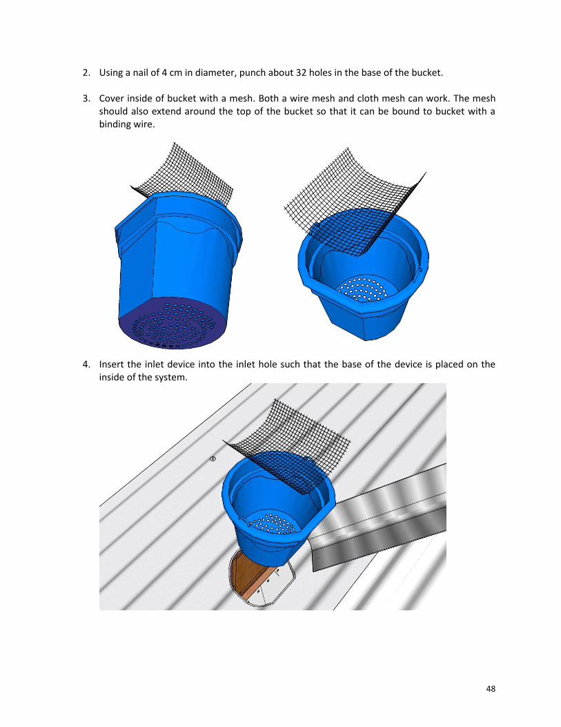
48
2. Using a nail of 4 cm in diameter, punch about 32 holes in the base of the bucket.
3. Cover inside of bucket with a mesh. Both a wire mesh and cloth mesh can work. The mesh should also extend around the top of the bucket so that it can be bound to bucket with a binding wire.
4. Insert the inlet device into the inlet hole such that the base of the device is placed on the
inside of the system.
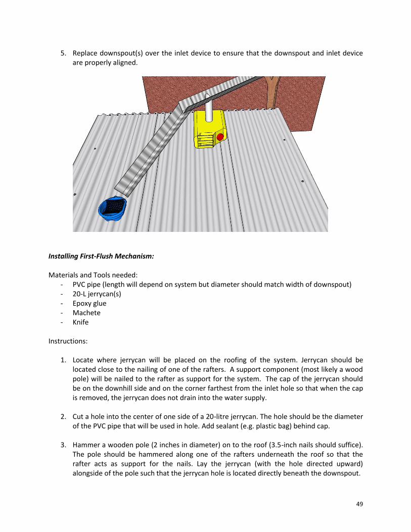
49
5. Replace downspout(s) over the inlet device to ensure that the downspout and inlet device are properly aligned.
Installing First-Flush Mechanism: Materials and Tools needed:
- PVC pipe (length will depend on system but diameter should match width of downspout) - 20-L jerrycan(s) - Epoxy glue - Machete - Knife
Instructions:
1. Locate where jerrycan will be placed on the roofing of the system. Jerrycan should be
located close to the nailing of one of the rafters. A support component (most likely a wood pole) will be nailed to the rafter as support for the system. The cap of the jerrycan should be on the downhill side and on the corner farthest from the inlet hole so that when the cap is removed, the jerrycan does not drain into the water supply.
2. Cut a hole into the center of one side of a 20-litre jerrycan. The hole should be the diameter of the PVC pipe that will be used in hole. Add sealant (e.g. plastic bag) behind cap.
3. Hammer a wooden pole (2 inches in diameter) on to the roof (3.5-inch nails should suffice).
The pole should be hammered along one of the rafters underneath the roof so that the rafter acts as support for the nails. Lay the jerrycan (with the hole directed upward) alongside of the pole such that the jerrycan hole is located directly beneath the downspout.

50
4. Using a machete, create slices (see image below) in the downspout such that the slices
created can be folded downwards. This configuration will help direct the water into the jerrycan via the PVC pipe and provide additional surface area for the epoxy. The downspout may have to be detached from the gutter for this step.
5. Cut a piece of PVC pipe that is long enough to connect the downspout hole to the jerrycan. The pipe should be large enough in diameter such that it spans the base of the downspout.30 If it isn’t, install an over-arching binding wire between the walls of the gutter directly over the hole created in Step 4. One edge of the PVC pipe should be cut at an angle such that this edge allows the pipe to align with the downspout while being perpendicular to jerrycan (see Image 4 of Appendix A1).
6. Apply epoxy glue liberally on the outsides of each connection (i.e. PVC-downspout and PVC-
jerrycan connections) to ensure that the epoxy does not come into contact with the runoff water (see Image 5 of Appendix A1). Ensure that the areas on which epoxy will be applied are clean and dry before applying the epoxy. Wait at least 10 minutes for the epoxy to dry.
7. After drying, install jerrycan against support on rooftop as shown in the image below.
8. Attach the jerrycans on to the support using binding wire or payan metal; this will deter
theft of jerrycan and keeps the first-flush mechanism stationary.
30 The pipe used for the system outlined in this manual is 3 inches in diameter, similar to the width of the downspout, which is about 3.5 inches.

51
Installing Overflow Mechanism: Materials and Tools needed:
- Mesh - Iron sheet scraps - Binding wire - Hammer and Nails
Instructions:
1. Create a 6-inch-diameter hole at ground level at one of the corners farthest from the household and on the downhill side of the structure. This will be where the overflow system is placed. The construction of this hole also requires cutting a semicircle into the tank frame, as shown in the image below.
2. From a corrugated iron sheet, make two gutter pieces that are about 9.25 inches in width and 20 inches in length.
3. Hammer down corrugation of iron sheets so as to create a gutter shape.
4. Firmly attach the metal mesh with binding wire to the outside of the first gutter piece. If desired, mesh attachment can be reinforced by using nails.
5. Cover the first gutter piece with the second gutter piece using binding wire so as to create a
cylinder shape. The overflow device should be around 5 inches in diameter, and be able to fit into the overflow hole made in the wall structure, as shown in the image below.
6. Insert overflow device into overflow hole such that the mesh faces downhill.
7. From the outside of the system, fill gaps of overflow hole with cement and hard rock. From
the inside of system, overflow mechanism should look like the image below.
8. If necessary, dig a channel with a shovel to route the overflow water to a desirable location.

52
Installing Tarpaulin (Tarp): Materials and Tools needed:
- Tarpaulin (5m x 4m) - 3-litre jerrycan - Nails - Hammer
Instructions:
1. Create washers for nails from plastic (a 3-litre jerrycan can be used). Cut out small rectangular pieces of plastic that are about 1.5 by 1.5 inches in size.
2. Using nails that are 3 cm (1.25 inches) in length, hammer nails into washers as shown in Image 6 in Appendix A1.
3. Fold the tarp such that it can be inserted into the system through the door on the wall
structure (ensure tarp has no holes). Fold the tarp such that the side of the tarp that will be on top is folded on the inside (i.e. the part facing away from the inside of the tank). Ideally, the white part of tarp should be the topside because a white background allows water contamination to be easily seen.
4. Insert the tarp into the inside of the system. This step will require two people, both of
whom should be barefoot to prevent damage and dirtying of the tarp.
5. Hammer the edges of the tarp on to the tank framework (wood structure) with the washer-and-nails created in step 2; the 5-metre sides of the tarp should be nailed along the 9-feet sides of the framework and the 4-metre sides of the tarp should be nailed along the 6-feet sides of the framework.

53
6. The tarp will not fit perfectly along the surface area of the tank; fold tarp at the corners such
that when water flows on to tarp, it is not able to fall behind the tarp or framework.
Installing Pump: Materials and Tools needed:
- Machete - Brick
Instructions:
1. Select position on one of the walls of the structure in which the pump will be installed. Position selected should ideally be at the center of the wall and the height of the wall should be tall enough to allow the pump to be sloped at an appropriate angle into the tank.31 One can angle the pump through the door to find the height/location where pump needs to be located. The angle at which the pump is placed should allow 3-4 inches between the bottom of pump pipe and base of tank (i.e. the pump pipe should not be touching the base of the tank once installed).
2. Using a machete, cut a hole into the side of the wall structure intended for the pump. This hole should be about 7 inches in width and 9 inches in height.
3. Angle pump through hole created. A brick can be set at the base of the tank and the bottom
of the pump pipe can be set on the brick in order to get the correct angle at which the pump should be inserted.
31 The hole for the pump created in the system for the purpose of creating this manual was located at about the same level as the top of the doorframe of wall structure.

54
Creating Base and Support for Pump: Materials and Tools needed:
- Machete - Cement - Bricks - Small rocks - Trowel
Instructions:
1. A platform needs to be built on which a water container can be placed while water is pumped from the pump into container. Below the hole made for pump installation, and right against the wall structure, dig a hole for platform that is about 1 foot along the wall structure and 2 feet perpendicular to the structure (see Image 7 of Appendix A1). The hole should be deep enough such that a jerrycan on a brick will fit comfortably under the spout of the pump. The hole may be about 4 inches deep, but the depth may be different for your system, depending on the terrain on which the system was built and the slope of the pump pipe.
2. After digging the hole for the platform, build the platform by first filling the platform hole with rocks then dirt. Lay about ½ inch of concrete above the rock/dirt layer and then insert bricks on to concrete layer.32 Also layer bricks using concrete along the wall structure up to where the pump is inserted into the wall structure. Insert rocks about an inch in diameter into the gaps between the pump and the bricks (see Image 8 of Appendix A1 for clarification).
32 Bricks used for the purposes of this construction manual were 9 x 5.5 x 4 inches

55
3. With concrete, cover the bricklayer and rocks inserted such that the pump apparatus looks like the image below.
Final Steps: Materials and Tools needed:
- Wash cloth - Bleach or detergent
Instructions:
1. Clean tarpaulin and remove brick before allowing system to catch rainwater.
56
4.3 User’s Guide
4.3.1 Usage Water Retrieval
1. Unlock the pump. 2. Place a clean bucket under the faucet to catch water from the pump. 3. Move the inner pipe of the pump up and down, at a slow and steady pace, to pump the
water out. Remember that you will have to pump several times before water starts to come out through the spout.
4. Remember to lock the pump when done in order to prevent unauthorized access. Note: Use of a bucket or pan to manually retrieve water from inside the tank could damage the tarpaulin.
First-Flush Runoff First flush is the initial runoff of rainfall after an extended period of no rain. It is important to discard this initial runoff as it contains pollution from the roof (from leaves, dirt, bird droppings, ash, etc.). According to Yaziz et al33, capturing 35 litres of rainfall per 100 square meters of roof area for first flush is sufficient for preventing pollution from the rooftop from entering the underground tank. Hence, your system should have more than one first-flush mechanism installed if the roof area from which water is collected is greater than 57 m2. If your system contains an automated first-flush mechanism:
1. Empty the first-flush tank(s) after two days of no rainfall in order to avoid standing water in the first-flush jerrycan(s). Emptying is done by unscrewing the cap of the jerrycan and allowing the first-flush water to flow out of the jerrycan. Either let the water drain off the roof onto the ground, or have a bucket ready on the downhill side of the roof to capture the water. Due to the potential pollution present in the first flush, this water should be not be used for household purposes and should instead be used for animals or in the garden.
2. At the start of the rainy season and during the dry season, ensure that the first-flush jerrycan(s) on the top of the roof is (are) empty and all of the gutters are clean.
If your system does not contain an automated first-flush mechanism:
1. At the start of the rainy season (or at the start of a storm event in the dry season), manually move the downspout away from the inlet hole in the roof of the structure to discard the first-flush water away from entering the underground tank. You can collect this water if desired.
2. After about 35 litres of first-flush rainfall per 100 square meters of roof space have been diverted, or until water appears to be clear and clean, place the gutter back over the inlet hole so that rainfall is again diverted into the underground tank.
33 Yaziz, M., Gunting, H., Sapari, N. and Ghazali, A. 1989 “Variations in rainwater quality from roof catchments.” Water Research, 23(6), 761-765.

57
Overflow Prevention Overflow occurs when the water in the tank exceeds the capacity allowed by the tarpaulin and starts to encroach on the walls of the mud structure, which can lead to structural damage to the mud walls. If your system has an automated overflow prevention mechanism: Ensure that the overflow hole is unobstructed by debris, that the mesh is well fitted to the pipe to prevent animals from entering the tank, and that overflow water is properly directed away from the structure. If your system does not have an automated overflow prevention mechanism: Monitor the water level in the tank. Whenever it is about to exceed the top of the tarpaulin, move the gutter away from the inlet hole to let the excess water run off the roof of the system and to prevent further tank flooding. Note: Ensure that the runoff does not cause erosion or flooding near the structure by constructing channels and grading that directs the excess water away from the system. Buckets or an aboveground tank may be used to catch the excess runoff for later use.
4.3.2 System Maintenance Cleaning the Tank Clean the tarpaulin when the tank is empty during the dry season and water can no longer be pumped. To clean the tarpaulin:
1. Remove shoes and clean feet. 2. Enter the tank barefoot. Be careful not to put too much pressure on the tarpaulin when
entering to prevent tears and damage. 3. Carefully remove any remaining water from the bottom of the tank. 4. Use a clean cloth and some bleach (or detergent) to clean the tarpaulin. 5. Check the tarpaulin for holes/tears. If holes are found, tarp will need to be replaced to
prevent water contamination and leakage. 6. Clean the inlet hole container and mesh.
Cleaning Gutters and Downspout The downspout and gutters should also be cleaned periodically; not all dirt and bacteria will be removed through the first-flush mechanism. As with the tarp, bleach or detergent can also be used to clean the gutters and downspouts. During cleaning, be careful not to put too much pressure on gutters that would bend them out of shape or dislocate them from their positions.

58
4.3.3 Periodic Maintenance Periodically check the system for the following conditions:
No termites are eating away at the wall structure,
The overflow mesh is secure and clean of debris,
The inlet hole mesh is clear of debris,
The gutters and downspout are clear of debris, and
If applicable, the first-flush jerrycan(s) is(are) leak-free and functioning properly. If termites are eating away at the structure, then this will reduce the lifespan of the wall structure from 20 years to about 8-10 years. While it is not necessary to rebuild the system immediately, it is important to note that, after about 8 years, the wall structure may need to be checked for structural stability and/or rebuilt. The overflow mesh, which is located at ground level, may be susceptible to rodents and other animals. If bite marks or other damages to the mesh are observed, immediately replace the mesh. If any of the components of the system need to be replaced – due to damage, leakage or other compromises in the system’s functionality – it is important to replace these components as soon as possible to prevent water contamination and water leakage. Projected costs for replacing certain components of the system are given below (excluding labor/installation costs):
- Pump – USD $40 (120,000 UGX) - Tarpaulin – USD $30 (90,000 UGX) - Structure – USD $30 (92,000 UGX) - Gutters and downspout – USD $10 (26,000 UGX) - First-flush mechanism – USD $10 (26,000 UGX) - Door – USD $20 (61,000 UGX)
59
5. Conclusion
5.1 Summary
This report presents the design process and the construction manual for an URWH system that can provide accessible water in rural areas in Uganda. After conducting a thorough literature review, interviewing in communities, and observing the construction and maintenance of the URWH system, it was determined that this system is the best option for this region and other regions with similar resources, climate, etc. While the system is applicable to many situations, the construction manual is not a completely comprehensive document for all possible construction and environment scenarios. For instance, the instructions are for a 4900-litre tank, but a tank of a larger size for community use may be desired (and thus a larger tarpaulin required). Alternatively, a sturdier walled structure made of brick and cement, instead of mud and wood, may be necessary in more earthquake-prone areas. In these cases, the report should be used as a baseline design and then modified as needed.
5.2 Future Steps
Since the URWH system discussed in this report was deemed to currently be the best option for this region and similar regions, the most important future steps for this project are to build more systems, impact more families and communities, and expand the region of influence of the system. This goal can be accomplished in many different ways, including:
Publishing this technical document. This action would: o Increase the accessibility of the URWH technology, o Minimize the need for an on-site skilled engineer during construction, and o Cut costs of the system by anywhere by as much as 60%.
Patenting the URWH system. This action would: o Give Go Organic Africa proper recognition for the innovation, o Prevent the idea from being rebranded or used for profit, and o Keep the system economically sustainable.
Increasing marketing of the technology to raise awareness about the importance of having a rainwater harvesting system
Obtaining more funding through a combination of donations and grants
Establishing construction management infrastructure in order to meet increased demand for systems and train citizens in the construction of the URWH system
Modifying the current system (re: materials, size, layout, etc.) for other regions for increased flexibility and accessibility
60
In addition to building more systems and expanding the region of influence, the system and its documentation could also continue to be improved. The construction manual was written after observing the construction of an URWH system and has not yet been tested in local communities for readability and comprehensiveness. Assessing the effectiveness of the manual itself for building a project without an on-site engineer would be beneficial for identifying weaknesses in the manual’s descriptions and for improving usability. Also, as mentioned in the ‘Analysis of System Before Innovation’ section, because these systems are only a couple of years old, continued community surveys and system examinations would allow for the evaluation of longer-term impacts, maintenance requirements, life span information and a more detailed risk analysis.

61
Acknowledgements The construction of the URWH system in the Kengoma village, and the subsequent creation of this report were possible with the guidance and assistance of the following people and organizations. A very warm and heartfelt thank you to the following:
People
Twinamatsiko Alphonse – Founder and Owner of Go Organic Africa Alphonse was the original designer of this URWH system and has installed more than 400 of these systems throughout Uganda. He led the installation of the URWH system in Kengoma village used for the creation of this report, and he also served as the SSLP water group’s mentor. He translated during community interviews, explained the construction process, and answered all questions regarding the URWH system.
Nabaasa Barnabas – Coordinator at KIHEFO Barnabas organized the transportation to and from the work site and was the point person for any logistics or communications between Go Organic Africa and KIHEFO. He helped with portions of the project including the excavation of the pit and the mudding of the structure.
Musiimenta Christoph James – Mason in Kengoma Village James is a local mason in Kengoma village. He assembled the roof of the URWH system structure, constructed the gutters and downspouts, implemented the first-flush mechanism, and installed the door shutter.

62
Nandinda Martin – Craftsman and Owner of Martin & Family Value Addition Martin constructed and installed the pump for the URWH system, and he also helped with the installation of the tarpaulin. In addition, he gave lessons to the research group as he demonstrated the construction and operation of the pump.
Esau Nuru & Mujuni Hilary – Community Workers Nuru and Hilary worked on the excavation of the pit and the mudding of the structure. They retrieved community resources like eucalyptus trunks for the structure and water for the mudding, and they assisted with the construction of the gutters and downspouts.
Organizations Child Family Health International (CFHI) CFHI coordinated between KIHEFO and Stanford Global Engineering Programs (GEP). They provided the backend support while the SSLP engineers were on the ground, ensuring participant safety and security. Special thanks to Robin Young for her logistical support from the onset of this project.
Kigezi Healthcare Foundation (KIHEFO) KIHEFO gave the SSLP engineers on-the-ground support, providing accommodations and transport before, during, and after the time of construction. In addition, the KIHEFO staff served as knowledgeable technical resources when the team was in the process of need-finding. Special thanks to Dr. Geoffrey Anguyo for his guidance given during our stay in Kabale.

63
Stanford Global Engineering Programs Stanford Engineering’s Global Engineering Programs (GEP) provided the means for the SSLP engineers to come to Kabale, Uganda and to participate in this opportunity to work with local organizations like KIHEFO and Go Organic Africa. Additionally, GEP facilitated a course during the Spring quarter leading up to the project that prepared students with travel logistics, what to expect and prepare for upon arrival, and information about asset-based community development and the current state of the topics examined on our trip. Special thanks to Tori Bianchi of GEP and Shoshanah Cohen of Community Engaged Learning (CEL) for their directing the SSLP group before our going to Kabale to do this project.
Go Organic Africa Go Organic Africa gave their expertise and support for this project. The SSLP team was able to utilize their knowledge and resources in order to construct the URWH system in Kengoma village. Go Organic Africa is a Community Based Organization (CBO). It started in 2010 with its head quarters in Kabale. Its mission is to improve household nutrition through consumption of diverse and nutritious foods. Go Organic Africa is spreading like wild fire to other parts of Africa, providing small farmers with the skills and knowledge of sustainable and organic farming.
Contact Information For more information on this project, please contact: Victoria W. Bianchi Stanford Global Engineering Programs Manager E-mail: [email protected] Phone: 650-498-0716 For more information on the URWH system, please contact: Go Organic Africa P.O Box 379, Kabale, Uganda – East Africa. E-mail: [email protected] Phone: +256 784 82 07 54 / +256 753 02 00 16

64
Works Cited
1. Biazin, B. et al. Rainwater harvesting and management in rainfed agricultural systems in sub-Saharan Africa – A review. Physics and Chemistry of the Earth. 2011.
2. Doyle, K.C. Sizing the First Flush and Its Effect on the Storage-Reliability-Yield Behavior of
Rainwater Harvesting in Rwanda. Thesis. Massachusetts, 2008.
3. Enninful, J.P. Rainwater Harvesting: A Sustainable Practice for Low-Income Housing in South Africa. Thesis. University of Witwatersrand, Johannesburg, South Africa. 2013.
4. Black, J. et al. Rainwater Harvesting Inventory of Kenya An Overview of Techniques,
Sustainability Factors, and Stakeholders. 2012
5. Agroforestry Centre (ICRAF). PO Box 30677 – 00100 Nairobi, Kenya.
6. JeanCharles, M. Rainwater Harvesting Systems for Communities in Developing Countries. Thesis. Michigan Technological University. 2007.’
7. Kabo-Bah, A. et al. Affordable Rainwater Harvesting Systems: A Collaborative Research
Effort. 11th International Conference on Urban Drainage, Edinburgh, Scotland, UK, 2008.
8. Pachpute, J.S. et al. Sustainability of Rainwater Harvesting Systems in Rural Catchment of Sub-Saharan Africa. Water Resources Management. 2009.
9. Stockholm Environment Institute. Rainwater Harvesting: A Lifeline for Human Well-Being.
United Nations Environment Programme.2009.
10. Vohland, K. et al. A review of in situ rainwater harvesting (RWH) practices modifying landscape functions in African drylands. Agriculture, Ecosystems and Environment. 2009.
11. Worm, J. et al. Rainwater Harvesting for Domestic Use. Agromisa Foundation and CTA,
Wageningen. Sponsored by ICCO and AIDEnvironment. 2006.
12. Yaziz, M. et al. Variations in rainwater quality from roof catchments. Water Research, 23(6), 761-765. 1989
13. WaterAid. Rainwater harvesting Technical Brief. January 2013.
14. Republic of Uganda; Ministry of Finance; Planning and Economic Development. Poverty
Eradication Action Plan (2004/5-2007/8). p. 168, 171. Retrieved 7 November 2011.
15. Bejarano, D. et al. Groundwater Pumping & Storage System: Summer Service Learning Program – Uganda 2015. September 2015.

65
Appendix
A1. Images to aid in Construction of URWH System
Image 1. Nails made from aluminium wire
Image 2. Valve with rubber flap on inside
Image 3. Gutter shape created from iron sheet
Image 4. One end of PVC cut at an angle

66
Image 5. Epoxy applied on exterior of PVC
Image 6. Creation of nails with washers
Image 7. Digging hole for pump platform
Image 8. Use of bricks and rocks to support pump

67
A2. Materials and Tools for Construction
Material Dimensions/ Description
Image Notes
Tank
Tarpaulin 5m x 4m, current brand being used: UEFACH.L.
Lines the inside of the tank to prevent seepage and contamination. Check for pinholes in material before buying. Expected mean time before failure: 10 years.
Nails 3 or 4 inch
For nailing the tarp into the wooden framework at the top of the tank.
Washers Squares: 1/2 inch by 1/2 inch
To prevent tears in tarp from nails (use between nail and tarp). Can be made from cutting up an old jerrycan or other plastic container.
Structure
Bricks/mud Approximately 64 ft3 of material needed
Used for construction of structure walls. Normally can be made from mixing the dirt from the excavated tank with water.
Wooden poles
14 feet of 3.5 inch diam., 31.5 feet of 3 inch diam., 150 feet of 2.5 inch diam. and 330 feet of 1.5 inch diam.
Used for construction of structure walls. Made from pine, eucalyptus, or any other strong wood that is readily available in the community.
Limestone Powder Powder, measured in basins
Used with ash and water to make plaster coating for structure walls. Often donated from the community. Can replace limestone powder with sand.
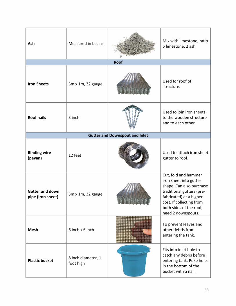
68
Ash Measured in basins
Mix with limestone; ratio 5 limestone: 2 ash.
Roof
Iron Sheets 3m x 1m, 32 gauge
Used for roof of structure.
Roof nails 3 inch
Used to join iron sheets to the wooden structure and to each other.
Gutter and Downspout and Inlet
Binding wire (payan)
12 feet
Used to attach iron sheet gutter to roof.
Gutter and down pipe (iron sheet)
3m x 1m, 32 gauge
Cut, fold and hammer iron sheet into gutter shape. Can also purchase traditional gutters (pre-fabricated) at a higher cost. If collecting from both sides of the roof, need 2 downspouts.
Mesh 6 inch x 6 inch
To prevent leaves and other debris from entering the tank.
Plastic bucket 8 inch diameter, 1 foot high
Fits into inlet hole to catch any debris before entering tank. Poke holes in the bottom of the bucket with a nail.
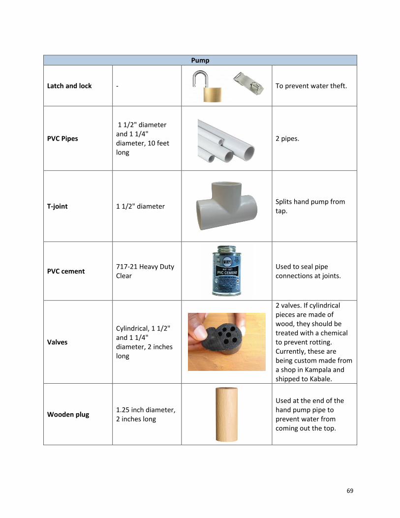
69
Pump
Latch and lock -
To prevent water theft.
PVC Pipes
1 1/2" diameter and 1 1/4" diameter, 10 feet long
2 pipes.
T-joint 1 1/2" diameter
Splits hand pump from tap.
PVC cement 717-21 Heavy Duty Clear
Used to seal pipe connections at joints.
Valves
Cylindrical, 1 1/2" and 1 1/4" diameter, 2 inches long
2 valves. If cylindrical pieces are made of wood, they should be treated with a chemical to prevent rotting. Currently, these are being custom made from a shop in Kampala and shipped to Kabale.
Wooden plug 1.25 inch diameter, 2 inches long
Used at the end of the hand pump pipe to prevent water from coming out the top.

70
Bricks 9" x 5.5" x 4"
To add structural stability for the base of the pump because of increased load and to prevent collapse.
Cement Powder 3 kg
To add structural stability for the base of the pump because of increased load and to prevent collapse.
Door
Door Frame and Shutter
50 inches wide, 60 inches high
Constructed by a woodworker in a town near the household.
Latch and lock -
To prevent water theft and ensure safety.
Overflow Mechanism
Mesh 6 inch x 6 inch
To prevent rodents from coming into the tank.
Iron sheet scraps 10 inch x 20 inch (2 scraps)
To create pipe through overflow hole and to route water away from structure walls.
Binding wire 1 foot
To attach mesh to pipe.

71
First Flush Mechanism
PVC Pipe 3 inch diameter, 5m long
To connect gutter to jerrycan.
Jerrycans 20 liters
For first flush collection.
Epoxy Glue
3-ton quick adhesive (for plastic, rubber, ceramics, wood, glass, metal). Current brand being used: Alteco.
To seal connections between gutter and PVC pipe and jerrycan and PVC pipe.
Tools and Miscellaneous
Measuring Tape -
Many uses.
PVC Hacksaw -
For cutting PVC pipes.
Hammers -
For hammering in nails and shaping iron sheets into gutters.

72
Shovel -
For excavation and mudding.
Hoe -
For excavation and mudding.
Pickaxe -
For excavation and mudding.
Wire Cutters -
For gutter construction.
Machete -
Many uses.
Trowel -
For applying concrete to pump foundation.
Sandpaper 60 grade
For pump construction.
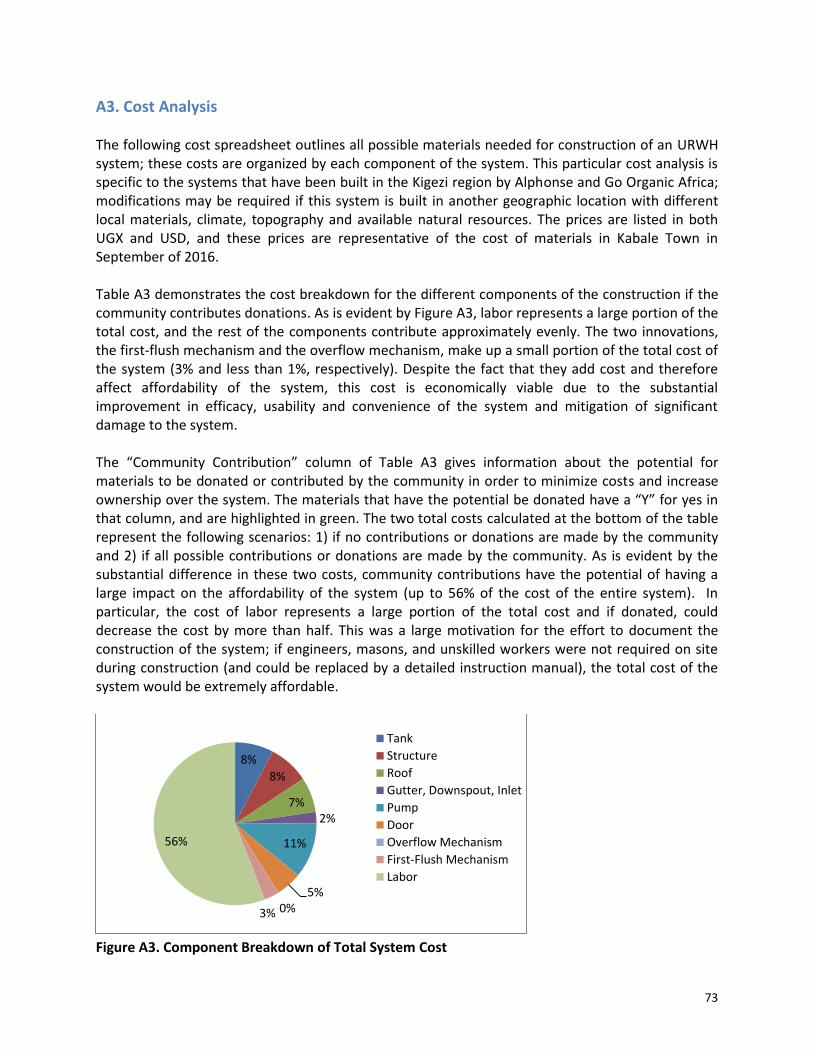
73
A3. Cost Analysis The following cost spreadsheet outlines all possible materials needed for construction of an URWH system; these costs are organized by each component of the system. This particular cost analysis is specific to the systems that have been built in the Kigezi region by Alphonse and Go Organic Africa; modifications may be required if this system is built in another geographic location with different local materials, climate, topography and available natural resources. The prices are listed in both UGX and USD, and these prices are representative of the cost of materials in Kabale Town in September of 2016. Table A3 demonstrates the cost breakdown for the different components of the construction if the community contributes donations. As is evident by Figure A3, labor represents a large portion of the total cost, and the rest of the components contribute approximately evenly. The two innovations, the first-flush mechanism and the overflow mechanism, make up a small portion of the total cost of the system (3% and less than 1%, respectively). Despite the fact that they add cost and therefore affect affordability of the system, this cost is economically viable due to the substantial improvement in efficacy, usability and convenience of the system and mitigation of significant damage to the system. The “Community Contribution” column of Table A3 gives information about the potential for materials to be donated or contributed by the community in order to minimize costs and increase ownership over the system. The materials that have the potential be donated have a “Y” for yes in that column, and are highlighted in green. The two total costs calculated at the bottom of the table represent the following scenarios: 1) if no contributions or donations are made by the community and 2) if all possible contributions or donations are made by the community. As is evident by the substantial difference in these two costs, community contributions have the potential of having a large impact on the affordability of the system (up to 56% of the cost of the entire system). In particular, the cost of labor represents a large portion of the total cost and if donated, could decrease the cost by more than half. This was a large motivation for the effort to document the construction of the system; if engineers, masons, and unskilled workers were not required on site during construction (and could be replaced by a detailed instruction manual), the total cost of the system would be extremely affordable.
Figure A3. Component Breakdown of Total System Cost
8%
8%
7%2%
11%
5%0%3%
56%
Tank
Structure
Roof
Gutter, Downspout, Inlet
Pump
Door
Overflow Mechanism
First-Flush Mechanism
Labor

74
Table A3. Cost Analysis Spreadsheet
Material Dimensions/Description UGX USD Quantity
Total USD
Community Contribution Notes
Tank
Tarpaulin
5m x 4m, current brand being used: UEFACH.L.
UGX 90,000.00
$ 27.27 1
$ 27.27 N
Lines the inside of the tank to prevent seepage and contamination. Check for pinholes in material before buying. Expected mean time before failure: 10 years.
Nails (1/2 kg) 3 or 4 inch
UGX 1,800.00
$ 0.55 1
$ 0.55 N
For nailing the tarp into the wooden framework at the top of the tank.
Washers
Squares: 1/2 inch by 1/2 inch
UGX -
$ - 100
$ - Y
To prevent tears in tarp from nails (use between nail and tarp). Can be made from cutting up an old jerrycan or other plastic container.
Subtotal $ 27.27
Structure
Bricks/ Mud
Approximately 64 ft3 of material needed
UGX -
$ - 1
$ - Y
Used for construction of structure walls. Normally can be made from mixing the dirt from the excavated tank with water. If mud is not available or not suitable, approximately 550 bricks will need to be used, and bricks are currently cost at UGX 500/brick.
Wooden poles
14 feet of 3.5 inch diam., 31.5 feet of 3 inch diam., 150 feet of 2.5 inch diam., 330 feet of 1.5 inch diam.
UGX 4,000.00
$ 1.21 10
$ 12.12 Y
Used for construction of structure walls. Made from pine, eucalyptus, or any other strong wood that is readily available in the community.
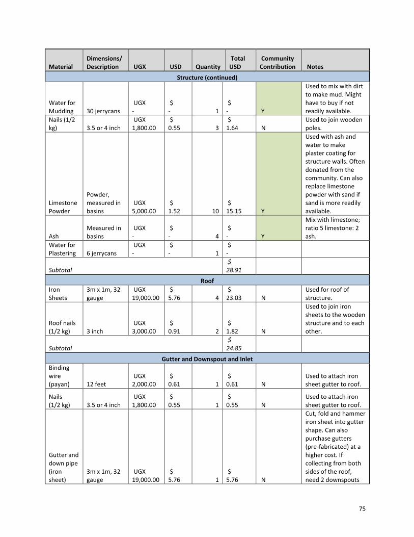
75
Material Dimensions/Description UGX USD Quantity
Total USD
Community Contribution Notes
Structure (continued)
Water for Mudding 30 jerrycans
UGX -
$ - 1
$ - Y
Used to mix with dirt to make mud. Might have to buy if not readily available.
Nails (1/2 kg) 3.5 or 4 inch
UGX 1,800.00
$ 0.55 3
$ 1.64 N
Used to join wooden poles.
Limestone Powder
Powder, measured in basins
UGX 5,000.00
$ 1.52 10
$ 15.15 Y
Used with ash and water to make plaster coating for structure walls. Often donated from the community. Can also replace limestone powder with sand if sand is more readily available.
Ash Measured in basins
UGX -
$ - 4
$ - Y
Mix with limestone; ratio 5 limestone: 2 ash.
Water for Plastering 6 jerrycans
UGX -
$ - 1
$ -
Subtotal $ 28.91
Roof
Iron Sheets
3m x 1m, 32 gauge
UGX 19,000.00
$ 5.76 4
$ 23.03 N
Used for roof of structure.
Roof nails (1/2 kg) 3 inch
UGX 3,000.00
$ 0.91 2
$ 1.82 N
Used to join iron sheets to the wooden structure and to each other.
Subtotal $ 24.85
Gutter and Downspout and Inlet
Binding wire (payan) 12 feet
UGX 2,000.00
$ 0.61 1
$ 0.61 N
Used to attach iron sheet gutter to roof.
Nails (1/2 kg) 3.5 or 4 inch
UGX 1,800.00
$ 0.55 1
$ 0.55 N
Used to attach iron sheet gutter to roof.
Gutter and down pipe (iron sheet)
3m x 1m, 32 gauge
UGX 19,000.00
$ 5.76 1
$ 5.76 N
Cut, fold and hammer iron sheet into gutter shape. Can also purchase gutters (pre-fabricated) at a higher cost. If collecting from both sides of the roof, need 2 downspouts

76
Material Dimensions/Description UGX USD Quantity
Total USD
Community Contribution Notes
Gutter and Downspout and Inlet (continued)
Mesh 6 inch x 6 inch
UGX 500.00
$ 0.15 1 $0.15 N
To prevent leaves and other debris from entering the tank.
Plastic bucket
8 inch diameter, 1 foot high
UGX 3,000.00
$ 0.91 1
$ 0.91 N
Fits into inlet hole to catch any debris before entering tank. Poke holes in the bottom of the bucket with a nail.
Subtotal $ 7.97
Pump
Latch and lock -
UGX 1,000.00
$ 0.30 1
$ 0.30 N
To prevent water theft.
PVC I
1 1/4" diameter, 10 feet long
UGX 25,000.00
$ 7.58 1
$ 7.58 N Inside pipe.
PVC II
1 1/2" diameter, 10 feet long
UGX 27,000.00
$ 8.18 1
$ 8.18 N Outside pipe.
T-joint 1 1/2" diameter
UGX 8,000.00
$ 2.42 1
$ 2.42 N
Splits hand pump from tap.
PVC cement
717-21 Heavy Duty Clear
UGX 9,000.00
$ 2.73 1
$ 2.73 N
Used to seal pipe connections at joints.
Valve I
Cylindrical, 1 1/4" diameter, 2 inches long
UGX 15,000.00
$ 4.55 1
$ 4.55 N
Made from two cylindrical pieces with holes drilled into them. Circular, flat pieces of rubber are used as flaps and attached to the cylindrical pieces by a nail. If cylindrical pieces are made of wood, they should be treated with a chemical to prevent rotting. Currently, these are being custom made from a shop in Kampala and shipped to Kabale. Valve II
Cylindrical, 1 1/2" diameter, 2 inches long
UGX 15,000.00
$ 4.55 1
$ 4.55 N
Wooden plug
1.25 inch diameter, 2 inches long
UGX -
$ - 1
$ - N
Used at the end of the hand pump pipe to prevent water from coming out the top.

77
Material Dimensions/Description UGX USD Quantity
Total USD
Community Contribution Notes
Pump (continued)
Skilled Labor I -
UGX 30,000.00
$ 9.09 1
$ 9.09 N
Currently being completed by Martin in Kabale. Pump construction takes 2 hours.
Bricks 9" x 5.5" x 4" UGX 300.00
$ 0.09 10
$ 0.91 Y
To add structural stability for the base of the pump because of increased load and to prevent collapse.
Cement Powder 3 kg
UGX 2,500.00
$ 0.76 3
$ 2.27 N
To add structural stability for the base of the pump because of increased load and to prevent collapse.
Skilled Labor II -
UGX 30,000.00
$ 9.09 1
$ 9.09 N
Installation of the pump into the structure (with cement).
Subtotal $ 39.39
Door
Door Frame and Shutter
50 inches wide, 60 inches high
UGX 50,000.00
$ 15.15 1
$ 15.15 N
Constructed by a woodworker in a town near the household. Took woodworker 4 hours to construct.
Latch and lock -
UGX 11,000.00
$ 3.33 1
$ 3.33 N
To prevent water theft and ensure safety.
Subtotal $ 18.48
Overflow Mechanism
Mesh 6 inch x 6 inch
UGX 500.00
$ 0.15 1
$ 0.15 N
To prevent rodents from coming into the tank.
Iron sheet scraps
10 inch x 20 inch (2 scraps)
UGX -
$ - 2
$ - N
To create pipe through overflow hole and to route water away from structure walls.
Binding wire 1 foot
UGX -
$ - 1
$ - N
To attach mesh to pipe.
Subtotal $0.15

78
Material Dimensions/Description UGX USD Quantity
Total USD
Community Contribution Notes
First Flush Mechanism
PVC Pipe
3 inch diameter, 5m long
UGX 12,500.00
$ 3.79 1 $3.79 N
To connect gutter to jerrycan.
Jerrycans 20 liters UGX 7,000.00
$ 2.12 2 $4.24 N
For first flush collection. May need 1 or 2 depending on size of roof collection area (35L for every 100 m2) and whether you are collecting from one or two sides of the roof.
Epoxy Glue
3-ton quick adhesive (for plastic, rubber, ceramics, wood, glass, metal). Current brand being used: Alteco.
UGX 4,000.00
$ 1.21 2 $2.42 N
To seal connections between gutter and PVC pipe and jerrycan and PVC pipe.
Subtotal $10.45
General Labor for Construction
Skilled Labor -
UGX 30,000.00
$ 9.09 10
$ 90.91 Y
Includes RWH engineers (7 days) and masons (3 days). UGX 30,000 per person per day, but they will often accept UGX 50,000 per week.
Unskilled labor -
UGX 15,000.00
$ 4.55 24
$ 109.09 Y
Includes excavation, water retrieval, gutter making and installation, structure construction and mudding, gathering and cutting wood. UGX 15,000 per person per day. Unskilled labor is often donated from the community.
Subtotal $ 200.00

79
Material Dimensions/Description UGX USD Quantity
Total USD
Community Contribution Notes
Optional (not included in total cost)
Measuring Tape -
UGX 6,000.00
$ 1.82 1
$ 1.82 Y Many uses.
PVC Hacksaw -
UGX 5,000.00
$ 1.52 1
$ 1.52 Y For cutting PVC pipes.
Hammers - UGX 10,000.00
$ 3.03 1
$ 3.03 Y
For hammering in nails and shaping iron sheets into gutters.
Shovel - UGX 10,000.00
$ 3.03 1
$ 3.03 Y
For excavation and mudding.
Hoe - UGX 10,000.00
$ 3.03 1
$ 3.03 Y
For excavation and mudding.
Pickaxe - UGX 10,000.00
$ 3.03 1
$ 3.03 Y
For excavation and mudding.
Wire Cutters -
UGX 10,000.00
$ 3.03 1
$ 3.03 Y
For gutter construction.
Machete - UGX 10,000.00
$ 3.03 1
$ 3.03 Y Many uses.
Trowel - UGX 10,000.00
$ 3.03 1
$ 3.03 Y
For applying concrete to pump foundation.
Knife - UGX 5,000.00
$ 1.52 1
$ 1.52 Y Many uses.
Transportation -
Depends on site. - 1
$ - Y
Transport of people and supplies to site. Need to factor in cost of gas, driver, and vehicle rental.
Sandpaper 60 grade UGX 3,000.00
$ 0.91 1
$ 0.91 Y
For pump construction
Aluminum binding wire
4-mm diameter
UGX -
$ - 1
$ - Y
For gutter construction.
Clay Stove and charcoal
UGX -
$ - 1
$ - Y
For melting the PVC and sealing the valve in; to heat tools to cut plastic
Subtotal $ 25.15
Summary:
Total (no donations, USD) $ 357.48
Total (all donations, USD) $ 129.30
Total (all donations, UGX) UGX 426,700.00
Percentage of system cost that can be contributed by the community 64%
Percentage of system cost for labor 56%

80
A4. Risk Analysis This URWH system design was first introduced in 2014 and has been installed and used in over 400 households. Over the last two years, several potential risks have been identified in the system’s construction, operations and maintenance. The system’s primary purposes are to collect and retain water and to prevent water contamination. Failure modes exist within the guttering system, pump system, tank and surrounding structure, along with the first-flush mechanism (if applicable). Table A.4.1 details potential risks in the construction and use of the system and Table A.4.3 displays the ‘failure mode’ and ‘effects analysis’ of each potential risk. A failure mode represents a situation that compromises the functionality and behaviour of the system and an effects analysis details how that situation will impact the use and longevity of the system. A more rigorous and quantitative risk analysis, which would draw conclusions about the probability of specific events happening and the strength and durability of important materials, would be helpful. However, due to the short time scale that these systems have been in use, proper testing, experimentation and analysis is not available at this time. The following tables provide information about what components and materials have the potential of failure and how detrimental that failure will be. Noting these risks is important for proper care, maintenance, and repair of the system so that maximum functionality is achieved over its lifespan. Table A.4.1 Risk Table
Category Risk # Description Potential Cause(s)
Materials R.1 First-flush jerrycan fails to hold water
Leak/Hole in jerrycan or connectors to gutter.
Materials R.2 First-flush jerrycan's adhesive degrades and causes toxins to enter water stream
Adhesive incorrectly applied.
Usage & Maintenance R.3 Tank Overflows Overflow hole is obstructed
Usage & Maintenance R.4 Animal/Rodent in tank
Overflow hole or inlet hole is compromised enabling rodents to enter tank
Materials R.5 Unable to pump water or significant spillage at pump.
Pump damaged or poorly constructed.
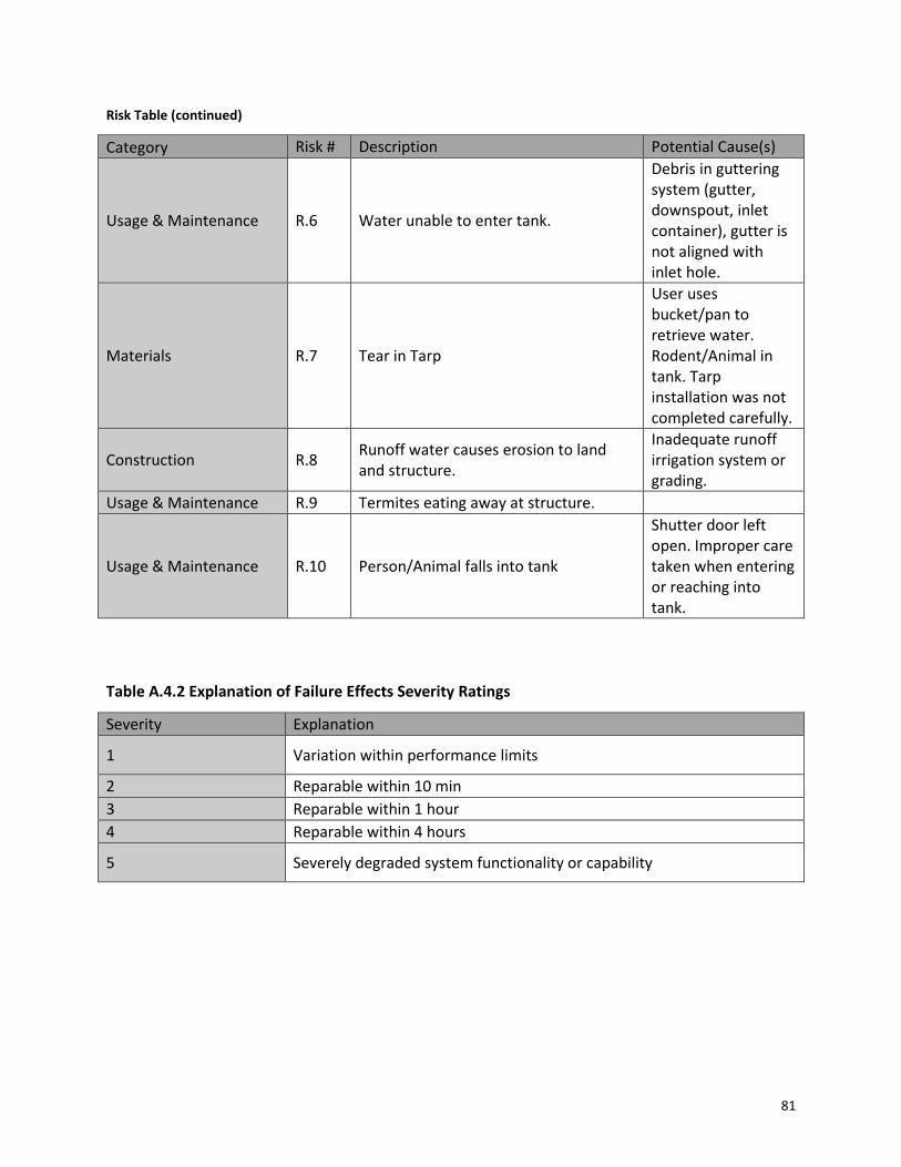
81
Risk Table (continued)
Category Risk # Description Potential Cause(s)
Usage & Maintenance R.6 Water unable to enter tank.
Debris in guttering system (gutter, downspout, inlet container), gutter is not aligned with inlet hole.
Materials R.7 Tear in Tarp
User uses bucket/pan to retrieve water. Rodent/Animal in tank. Tarp installation was not completed carefully.
Construction R.8 Runoff water causes erosion to land and structure.
Inadequate runoff irrigation system or grading.
Usage & Maintenance R.9 Termites eating away at structure.
Usage & Maintenance R.10 Person/Animal falls into tank
Shutter door left open. Improper care taken when entering or reaching into tank.
Table A.4.2 Explanation of Failure Effects Severity Ratings
Severity Explanation
1 Variation within performance limits
2 Reparable within 10 min
3 Reparable within 1 hour
4 Reparable within 4 hours
5 Severely degraded system functionality or capability

82
Table A.4.3 Failure mode and effects analysis (FMEA)
Failure Mode #
Identification of Item or Function
Failure Mode Possible Cause(s) Notes Failure Effects Severity
F.1 Pump System
Failure to pump water out of tank
Pump is damaged or defective.
Requires a technical expert to come examine the pump. Also requires concrete support to be removed.
5
F.2 Structural Tank Overflows
Overflow hole is obstructed or there is no overflow hole and user forgets to move gutter.
Can result in damage to structure and land.
3
F.3 Water Integrity
Tank Water Contaminated
Tear in tarp or over-flow hole is compromised, allowing rodents to enter tank. Jerrycan's adhesive degrades and causes toxins to enter water stream. Rodent/Animal in tank.
May require replacement of tarp.
5
F.4 System Tank unable to collect rainwater
Debris in gutter system backing up water before inlet. Jerrycan fails to hold water. Hole in tarp.
May require replacement of tarp.
4

83
A5. Community Interviews The following set of questions was created to guide the conversations with the households and gather information about all aspects of water access: underground storage, water use, available materials, water quality, culture, and gender roles.
A.5.1 All Interview Questions:
1. Underground Storage a. What time of year and how often do you run out of water? b. Do you ever clean the tank (and gutters) and if so, how? c. Do you use the system during the whole year? d. Any experiences with leakage, overflow, or erosion?
i. How do you monitor when you need to manually move the pipe? e. How effective have you been at monitoring and avoiding first-flush flows? f. Tell us about your experience using the pump. g. How do you feel about the quality or cleanliness of the water and does it change
throughout the year? h. Do you have problems with security? i. What would you change about the system? j. Who uses the system? k. What do you use the system for? l. How has this system changed your habits during the wet seasons? The dry season?
i. Did your water usage increase/decrease/stay the same since construction of the system? Does this depend on the season?
m. If you would pay for a system like this, what would you be willing to pay? n. Has the system met your expectations? How do you feel about the system? o. What concerns do you have about the system? p. Would you recommend the system to your friends? q. How did you go about getting this system installed? r. Did you contribute in any way to construction of your system or system in the
community? s. What do you think of the way that the system looks or takes up space? t. Land use: what did you have to sacrifice for use of this land for the system?
2. Water Access/Availability
a. How do you get water? b. How have people gotten water in the past? c. How often do you get water? d. Who fetches the water? e. How long does it take you to get water? f. Do your water sources ever run dry? g. What are your back-up plans? h. Do you feel a need for an alternative water source? i. What containers do you use and where do you get them? Any materials you avoid?

84
j. Where is your source? Do you have more than once source? k. Do you treat the water? l. What do you use the water for? m. Do you notice changes in the water throughout the year? n. How many litres of water does your family use per day? o. How do you allocate your water for different household uses? p. What would you improve about your methods for getting water? q. What problems have you experienced with getting and using water? r. Any word-of-mouth methods that you have heard of? s. How far would you be willing to walk for water?
3. Common Village Materials
a. What containers do you use for cooking, storing? b. What materials are these containers made of? c. Where do you get these containers? d. What materials is your house made out of? e. What materials are abundant in this region?
4. Quality
a. Do you boil your water? What fuel do you use to boil? b. Do you take any other measures to clean your water (sedimentation, disinfect, etc.)? c. How long would you be willing to wait for a filtration system to clean your water? d. Would you be willing to learn about water filtration and participate in maintaining a
filtration system?
5. Culture/Household Roles a. Who usually collects the water? Men or women? b. Do you work together with other households for certain efforts? c. What do women do during the day? Men? d. Who takes care of the kids? Who cooks? Who boils water? e. Who provides money and food for the household? f. Who handles the financials of the household? g. What do you consider when adding things onto your property? Aesthetics? Are
some materials acceptable and some are not? h. How much land do you own and how much space do you have on your property?
6. General
a. Are any other NGOs involved in community infrastructure development, particularly with regards to water catchment?
b. Have you noticed any other rainwater catchment systems in the area that is different than these?
c. Did earlier generations use any methods that you know about?
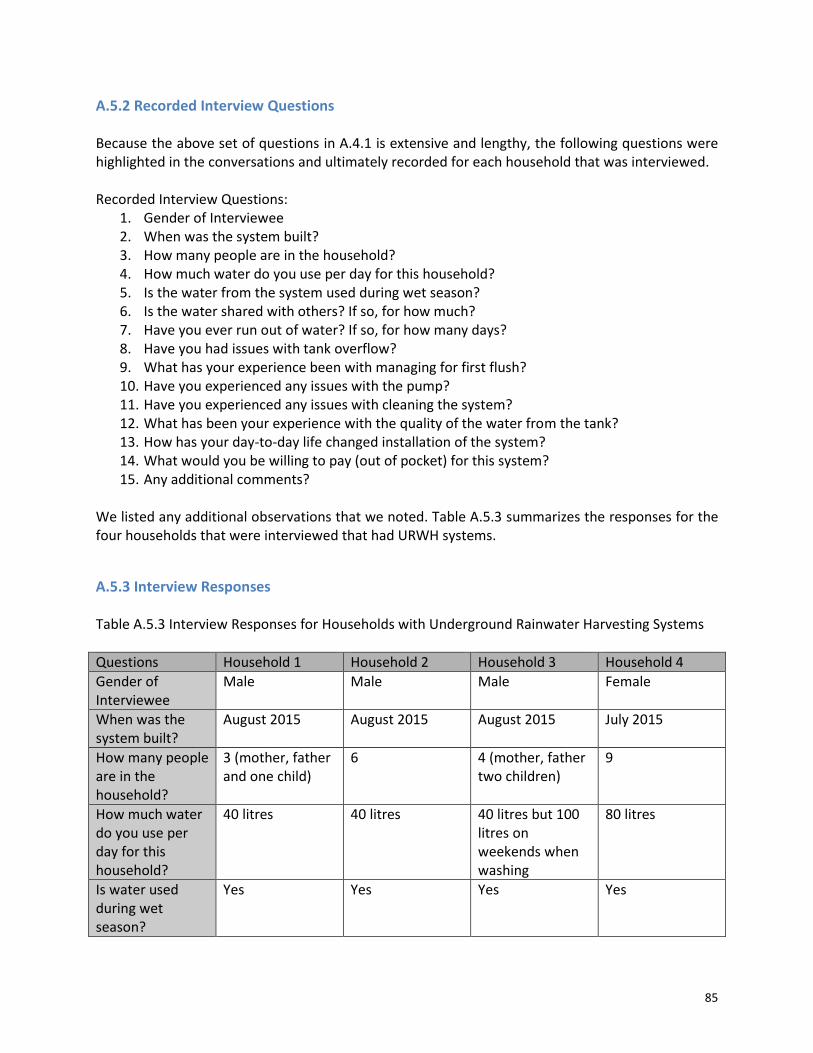
85
A.5.2 Recorded Interview Questions Because the above set of questions in A.4.1 is extensive and lengthy, the following questions were highlighted in the conversations and ultimately recorded for each household that was interviewed. Recorded Interview Questions:
1. Gender of Interviewee 2. When was the system built? 3. How many people are in the household? 4. How much water do you use per day for this household? 5. Is the water from the system used during wet season? 6. Is the water shared with others? If so, for how much? 7. Have you ever run out of water? If so, for how many days? 8. Have you had issues with tank overflow? 9. What has your experience been with managing for first flush? 10. Have you experienced any issues with the pump? 11. Have you experienced any issues with cleaning the system? 12. What has been your experience with the quality of the water from the tank? 13. How has your day-to-day life changed installation of the system? 14. What would you be willing to pay (out of pocket) for this system? 15. Any additional comments?
We listed any additional observations that we noted. Table A.5.3 summarizes the responses for the four households that were interviewed that had URWH systems.
A.5.3 Interview Responses Table A.5.3 Interview Responses for Households with Underground Rainwater Harvesting Systems
Questions Household 1 Household 2 Household 3 Household 4
Gender of Interviewee
Male Male Male Female
When was the system built?
August 2015 August 2015 August 2015 July 2015
How many people are in the household?
3 (mother, father and one child)
6 4 (mother, father two children)
9
How much water do you use per day for this household?
40 litres 40 litres 40 litres but 100 litres on weekends when washing
80 litres
Is water used during wet season?
Yes Yes Yes Yes
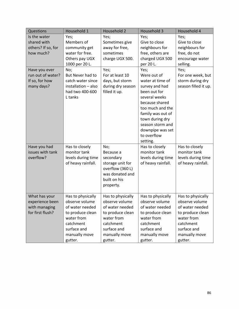
86
Questions Household 1 Household 2 Household 3 Household 4
Is the water shared with others? If so, for how much?
Yes; Members of community get water for free. Others pay UGX 1000 per 20 L.
Yes; Sometimes give away for free, sometimes charge UGX 500.
Yes; Give to close neighbours for free, others are charged UGX 500 per 20 L.
Yes; Give to close neighbours for free, do not encourage water selling.
Have you ever run out of water? If so, for how many days?
No; But Never had to catch water since installation – also had two 400-600 L tanks
Yes; For at least 10 days, but storm during dry season filled it up.
Yes; Were out of water at time of survey and had been out for several weeks because shared too much and the family was out of town during dry season storm and downpipe was set to overflow setting.
Yes; For one week, but storm during dry season filled it up.
Have you had issues with tank overflow?
Has to closely monitor tank levels during time of heavy rainfall.
No; Because a secondary storage unit for overflow (360 L) was donated and built on his property.
Has to closely monitor tank levels during time of heavy rainfall.
Has to closely monitor tank levels during time of heavy rainfall.
What has your experience been with managing for first flush?
Has to physically observe volume of water needed to produce clean water from catchment surface and manually move gutter.
Has to physically observe volume of water needed to produce clean water from catchment surface and manually move gutter.
Has to physically observe volume of water needed to produce clean water from catchment surface and manually move gutter.
Has to physically observe volume of water needed to produce clean water from catchment surface and manually move gutter.
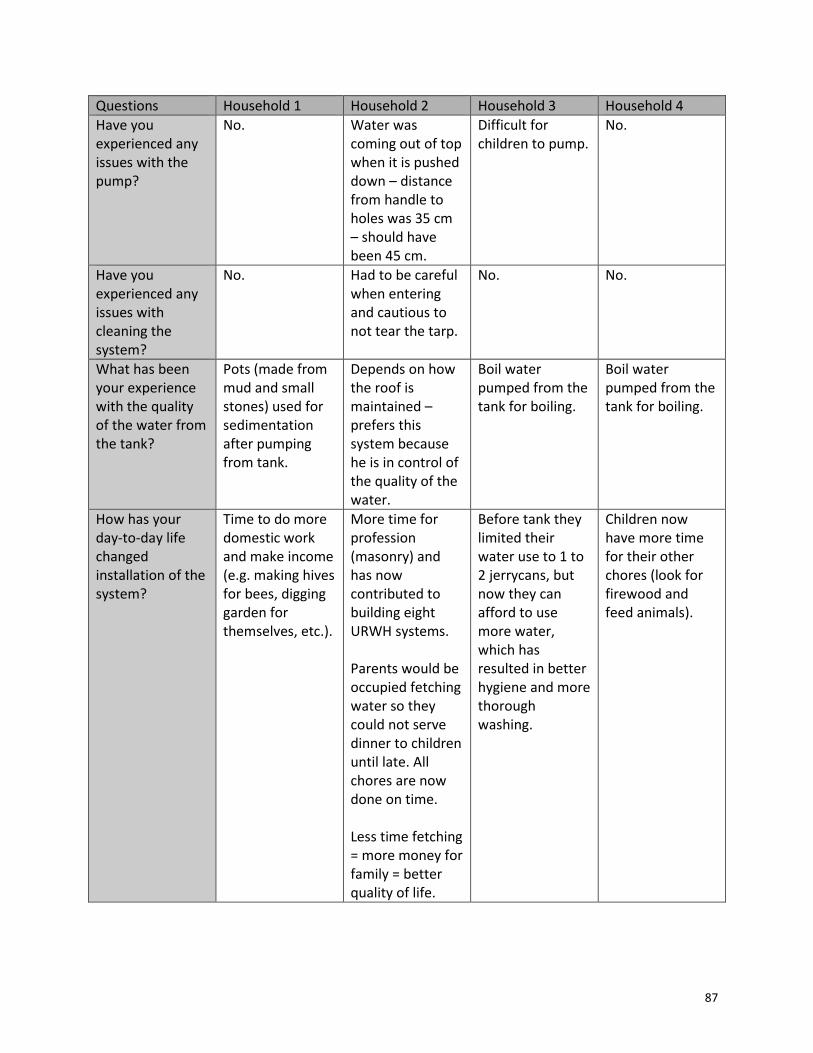
87
Questions Household 1 Household 2 Household 3 Household 4
Have you experienced any issues with the pump?
No. Water was coming out of top when it is pushed down – distance from handle to holes was 35 cm – should have been 45 cm.
Difficult for children to pump.
No.
Have you experienced any issues with cleaning the system?
No. Had to be careful when entering and cautious to not tear the tarp.
No. No.
What has been your experience with the quality of the water from the tank?
Pots (made from mud and small stones) used for sedimentation after pumping from tank.
Depends on how the roof is maintained – prefers this system because he is in control of the quality of the water.
Boil water pumped from the tank for boiling.
Boil water pumped from the tank for boiling.
How has your day-to-day life changed installation of the system?
Time to do more domestic work and make income (e.g. making hives for bees, digging garden for themselves, etc.).
More time for profession (masonry) and has now contributed to building eight URWH systems. Parents would be occupied fetching water so they could not serve dinner to children until late. All chores are now done on time. Less time fetching = more money for family = better quality of life.
Before tank they limited their water use to 1 to 2 jerrycans, but now they can afford to use more water, which has resulted in better hygiene and more thorough washing.
Children now have more time for their other chores (look for firewood and feed animals).
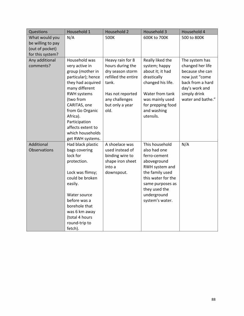
88
Questions Household 1 Household 2 Household 3 Household 4
What would you be willing to pay (out of pocket) for this system?
N/A 500K 600K to 700K 500 to 800K
Any additional comments?
Household was very active in group (mother in particular); hence they had acquired many different RWH systems (two from CARITAS, one from Go Organic Africa). Participation affects extent to which households get RWH systems.
Heavy rain for 8 hours during the dry season storm refilled the entire tank. Has not reported any challenges but only a year old.
Really liked the system; happy about it; it had drastically changed his life. Water from tank was mainly used for prepping food and washing utensils.
The system has changed her life because she can now just “come back from a hard day’s work and simply drink water and bathe.”
Additional Observations
Had black plastic bags covering lock for protection. Lock was flimsy; could be broken easily. Water source before was a borehole that was 6 km away (total 4 hours round-trip to fetch).
A shoelace was used instead of binding wire to shape iron sheet into a downspout.
This household also had one ferro-cement aboveground RWH system and the family used this water for the same purposes as they used the underground system’s water.
N/A

89
A6. Slideshow Presentation
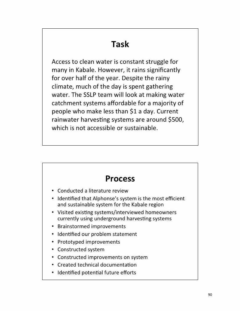
90
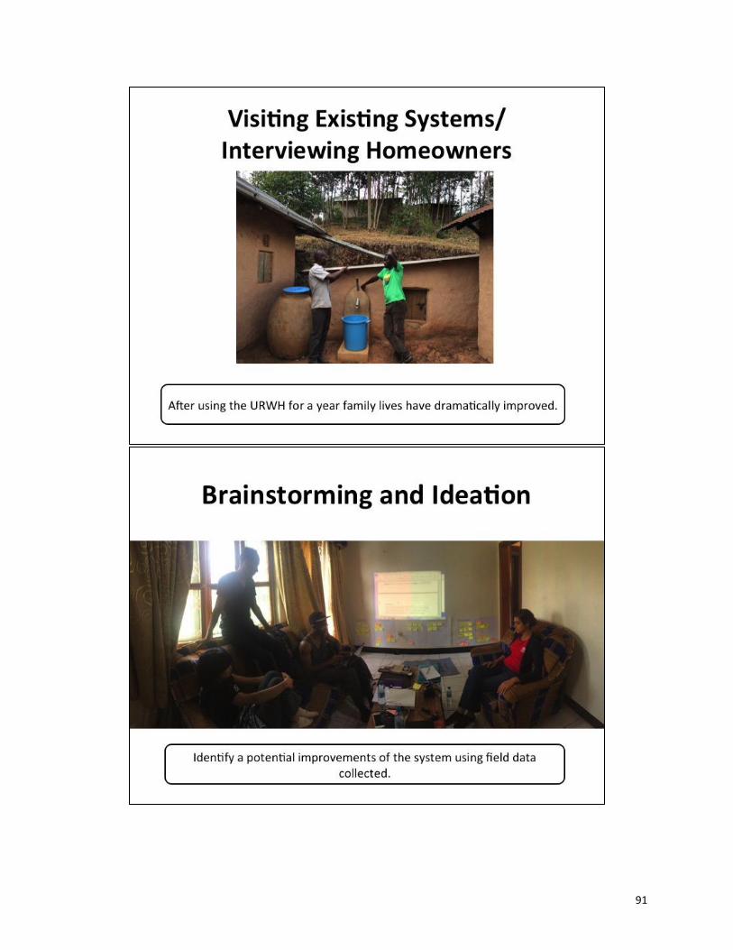
91

92
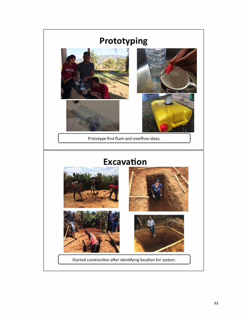
93
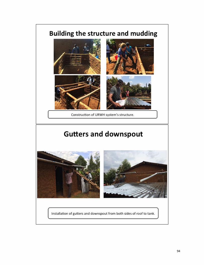
94

95

96

97

98
Contact Information For more information on this project, please contact: Victoria W. Bianchi Stanford Global Engineering Programs Manager E-mail: [email protected] Phone: 650-498-0716 For more information on the URWH system, please contact: Go Organic Africa P.O Box 379, Kabale, Uganda – East Africa. E-mail: [email protected] Phone: +256 784 82 07 54 / +256 753 02 00 16