underground parking garages changing perceptions on smoke
TRANSCRIPT
PROCEEDINGS, Fire and Evacuation Modeling Technical Conference 2011
Baltimore, Maryland, August 15-16, 2011
1
UNDERGROUND PARKING GARAGES – CHANGING PERCEPTIONS ON SMOKE
CONTROL CRITERIA AND COMBINING AN INTEGRATED SYSTEM FOR SMOKE
CONTROL AND VENTILATION.
Author: Netanel Donna1
Co-Author: Shmuel Netanel, FPE.PE.
S.Netanel Engineers and Consultant Ltd of Eidan Group.
& Offstream Studios, Israel
11 moshe Levi St.
Rishon-Le-Zion, Israel
e-mail: [email protected]
www.eidangroup.com
ABSTRACT
Underground parking garages are either fully or
partially closed. While only some of the partially
closed garages are required by standard and
regulations to install an electro-mechanical smoke
control system, fully enclosed garages that exceed
one underground level are always required to install
such systems.
Smoke Control and Ventilation (SCV) system
designers, along side fire protection engineers, are
facing three major challenges: The first maintaining
Air Quality levels according to health and
environmental regulations by means of toxic gas
extraction (Co, Co2, Nox). The second by providing a
Smoke Control system for emergency fire situations,
which in many cases are held to building Tenability
standards, among them smoke layer height, which is
rarely achievable in low ceiling clearance facilities.
And last by designing an integrated all-in-one
solution for both demands.
While Israeli Health and Environmental Standards
and Regulations define at least 8 Air changes per
hour, using an extraction of 20% from lower layers
(floor level) and 80% from Higher Layers (ceiling
level) alongside a PPM threshold, Fire and rescue
authorities and Buildings construction regulations
require only 6 Air changes per hour (adopting
American NFPA Standard), and must effectively
extract smoke from upper ceiling level.
Under these integrated requirements, system
designers tend to almost automatically design a
system that is based on Vents, Jet Fans and Air ducts,
resulting in a complex cost-ineffective system that is
high on installation costs, energy consumption and is
rarely esthetic to the eye.
This paper will present a case study portraying a
change in perception regarding smoke control
demand criteria for underground parking garages -
"Smoke control by smoke zones" utilizing an
optional criteria as proof of sufficient ventilation –
"Airflow Threshold" for the mater of CO evacuation.
Both new perceptions are approved and acceptable by
local authorities in Israel while maintaining a realistic
and economic viable solution.
INTRUDOCTION
Underground parking garages come in a variety of
design characteristics. They can be fully or partially
closed, partially or completely underground, consist
of one floor or several and vary in motor capacity,
usage, congestion and size.
While only some of the partially closed garages are
required by standard and regulations to install an
electro-mechanical Smoke Control and Ventilation
(SCV) systems, fully enclosed garages that exceed
one underground level are always required to install
such systems.
Underground garages are unique in their low
clearance ceiling height between 2.2m to 3m
(including cable and duct area) and by being a large
compartment area that usually lacks separation by
walls and distinct fire zones. In addition, the use of
fire resistant walls and doors is rarely present.
THE MAJOR CHALANGES DESIGNER ARE
FACING
When designing an underground garage, SCV system
designers, alongside fire protection engineers, face
three major challenges: Maintaining Tenability
conditions on egress routes for evacuation and rescue
times in case of fire; maintaining a level of tenable
Air-quality for daily use; designing an integrated, all-
in-one solution, for both emergency and daily use
demands.
1. Air Quality
Since underground garage facilities are not naturally
ventilated, system designers and engineers are
required to take in account several air quality issues,

PROCEEDINGS, Fire and Evacuation Modeling Technical Conference 2011
Baltimore, Maryland, August 15-16, 2011
2
a challenge of which the most problematic is high
levels of Carbon monoxide (CO) gasses emitted by
vehicles entering, existing and traveling through the
domain.
Other issues to be taken under consideration are the
presence of oil, gasoline fumes, nitrogen oxides
(NOx), Co2 and smoke haze from diesel engines [10].
Furthermore, in the near future, adaptation to new
energy carriers due to global warming issues must be
taken under consideration in both ventilation aspects
and risk assessments for emergency scenarios.
Designers need to take under consideration the
emission of different range of gasses that are still
under study and experiment. These gasses and are not
yet addressed in current regulations [12].
Regulation addressing the issue of Air-quality level
and the system's requirements to maintain Tenable
conditions for normal operation of underground
garages vary on a international, national and local
level. Part of the regulation codes address the PPM
threshold for CO exposure while others only address
the number of air changes (ACH) per hour, or state a
sufficient extraction of air according to gross floor
area.
To demonstrate this inconsistency:
NFPA 88A [2] states the fixed ventilation of 5 L/s-
M2 of floor area is the minimum required.
NFPA 502 [6] states CO exposure PPM threshold to
be only for fire emergency.
ANSI/ASHRAE Standards [7] 62-1989 state that a
fixed ventilation of 7.62 L/s-M2 of floor area is the
minimum required while including a PPM threshold
exposure time of 8 hours for 9 PPM and 1 Hour for
35 PPM .(More examples can be found in reference
10)
2. Smoke Control system criteria
Regulation addressing the issue of smoke control and
smoke management for underground parking garages
is almost non-existent in terms of building usage for
human occupancy. These structures are at times
addressed as a storage occupancy areas or vast space
areas [3].
NFPA 204 [5] is at times used as a guide for smoke
and heat venting in underground parking garages.
This code addresses the smoke layer boundary height
and temperature for building spaces with ceiling
heights that permit the fire plume and smoke layer to
develop.
This design criteria is rarely met when addressing
low clearance spaces.
A smoke management system shall be adopted and
designed to minimize the impact of smoke upon
occupants and emergency services personnel.
The main criteria for smoke management are to
provide tenable conditions within the building for the
time required by occupants to evacuate to a safe area.
The smoke management system should also provide
suitable conditions for emergency services to enter
the building, assist with the evacuation, rescue
occupants and initiate fire fighting strategies. Smoke
layer Criteria is usually regarded as the threshold of
smoke layer height ranging between 1.8m-2.5m [4].
Furthermore, Fire and rescue authorities in Israel
require at least 6 air changes per hour [8], and expect
smoke to be evacuated completely rather than
managed and contained.
3. Integrating an all-in-one coast effective system
When presented with such integrated requirements of
both normal operation ventilation system and
emergency ventilation system, designers tend almost
automatically to design a system that is based on
Vents, Jet Fans and Air ducts, resulting in a complex
cost-ineffective system that is high on installation
costs, energy consumption and rarely esthetic to the
eye.
OUR GOAL
Meeting with both authorities integrated requirements
while maintaining a viable, cost-effective, energy
saving, low maintenance system should result in a
system that is neither over nor under the required
safety and egress measures.
ALTERNATE PRECEPTION ON SMOKE
CONTROL
Past experience teaches us that retaining and
maintaining the building and code regulating of
smoke layer height as a Tenability factor on low
height ceiling such as underground parking, is neither
applicable nor practical. Thus the need to search for a
more realistic and appropriate criteria on the
challenge of smoke control for this type of building.
In this paper we will examine "Smoke zones"
approach as alternative criteria to smoke layer height
for tenability objectives. Based on the design
flexibility described in the NFPA Life Safety guide,
chapter 5[4], and the NFPA Handbook of Fire
Protection Engineering [1]: using a performance
based design to achieve the goals of a reasonable
level of life safety and achieving of objectives
regarding safety level, such as the protection of
occupants not intimate with the initial fire
development, for the time needed to evacuate,
relocate, or defend oneself in place. Integrated with
tenability criteria of maintaining tenability conditions
on egress routs [6] and to provide clear path access
for fire fighters and rescue team.
We will portray our alternative as satisfying for these
goals and objectives.
PROCEEDINGS, Fire and Evacuation Modeling Technical Conference 2011
Baltimore, Maryland, August 15-16, 2011
3
Smoke Zones
A "Smoke Zone" is a pre-defined area in which
smoke layer and fire effect will be restricted and
maintained throughout. The goal is to maintain this
area in a steady state of smoke capacity. And to
prevent smoke layer from traveling between building
levels thus preventing it from obscuring egress routes
and rescue routes. This approach incorporates the use
of "Push-Pull" method for creation of Barriers and
Exit Points and the use of Smoke Screens. By
implementing this approach we comply to "smoke
control" objectives rather than commonly expected
"Full Smoke Clearance".
ALTERNATE PRECEPTION ON AIR
QUALITY CONTROL
Over design in regulation demands on air changes of
7.6 ACH (ANSI) [7], 8 ACH (Israeli Environmental
Regulations) [8], 5 ACH (NFPA calculated for a
2.5m ceiling) [2] alongside the 20%/80% division of
duct location, usually leads to an over kill system
and an ineffective duct usage.
As a goal air in the underground structure should be
circulated for ventilation rather then being
completely purified. By using an air circulation of
acceptable "Airflow threshold" approach, which
introduces fresh air into the vicinity we lower Toxic-
concentrations and achieve the ventilation goals at
hand. The Air Quality criteria of PPM concentration
are monitored in this approach by CO measurement
detectors.
Airflow Threshold
Definition of "Airflow threshold" – Maintenance of
air flow of at least 0.5 m/s as a satisfying proof of air
circulation in individual parking level has been
agreed via collaboration and consultant with the local
authority having jurisdiction, for this matter The
Environmental authorities in Israel which agreed on
the criteria for future regulation demands.
CASE STUDY
As a case study for the above goals and challenges
we will examine the CFD Analysis of the Azriely
Group's Hi-Tech Center, Holon .A 4 story
Underground Parking lots.
This Case is suitable for the goal at hand for it is a
fully closed underground garage, with partially open
characteristics, such as ceiling apertures by means of
"English courts" and a central atrium opened to the
atmosphere. (This criteria does not meet code
definition for open garages, it is used solely for
descriptive purposes)
Preliminary System Design for ventilation and smoke
control was based on natural ventilation. This meets
with local regulations for parking garages that have at
least 2% of the ceiling area open [8]. Furthermore,
the investor's architectural design criteria had allowed
natural light to flow into the internal domain via the
"English courts"
We were asked to check and advise on the subject of
an all-in-one system to meet both ventilation and
smoke control demands and standards.
CFD Analysis
The CFD Analysis was carried out using the FDS –
Fire Dynamics Simulator Version 5, by NIST. FDS
is a CFD fire Model that uses the Large Eddy
Simulation (LES) Techniques to calculate the gas
density, velocity, temperature, pressure and
concentrations in each control volume. More on FDS
model can be found in reference [13].
Preparation of Run Files and Models where made
using Pyrosim Software version 2010, By
Thunderhead Engineering.
Smoke View was used in order to visualize the output
data.
The Model is in Ideal Conditions. No winds are
present. Ambient Temperature 20cº
An egress simulation has been conducted for
estimated evacuation times, as a part of the tenability
criteria demands regarding maintaining egress routes.
Garage Characteristics and Geometry:
A 4 Level Underground Garage. Each level is
approximately 20,000 Square meters (net area). The
Full scale model dimension: 200m (L) x 150m (W) x
14.5m(H)
Lower Levels -4 and -3 are fully closed
Upper Levels -2 and -1 are partially opened. (This
criteria, does not meet code definition for open
garages, only for descriptive purposes)
All 4 Levels Share a Central open air atrium in the
middle. And a row of "English courtyards" on the
floor out lines
Ceiling Height:
Floor -4 Ceiling Height 2.5m
Floor -3 Ceiling Height 2.5m
Floor -2 Ceiling Height 2.5m
(Double height on loading/unloading Zone)
Floor -1 Ceiling Height 2.5m
Atrium Ceiling Opening dimensions:
Floor -4 Atrium open dimensions 174 m2
Floor -3 Atrium open dimensions 341 m2
Floor -2 Atrium open dimensions 535.5 m2
Floor -1 Atrium open dimensions 722.75 m2

PROCEEDINGS, Fire and Evacuation Modeling Technical Conference 2011
Baltimore, Maryland, August 15-16, 2011
4
English Courtyards Opening dimensions:
Floor -4 Total Ceiling Opening 326m2
Floor -3 Total Ceiling Opening 270m2
Floor -2 Total Ceiling Opening 142m2
Floor -1 Total Ceiling Opening 38m2
Entrance Ramp dimensions:
To Level -4 – None
To Level -3 – None
To Level -2 – 96 m2
To Level -1 – 58 m2
Figure 1: Azriely Group "Hi-tech center Holon"
Underground Garage CFD Model
(Architectural Model version 2.0)
Methodology
In order to check effectiveness and usability of the
system design, an Evacuation-analysis has been
carried out to determine evacuation and egress time,
followed by two fire scenarios selected according to
FPE Risk analysis:
Scenario 01 - Car Fire @ Park level -4
Scenario 02 - HGV Fire @ Loading/Unloading Zone
Park level -2. (Not presented in this article)
CFD engineering analyses for performance design is
carried out following this methodology:
Figure 2: Design Process for simulations
Following this chart of methodology, our CFD
analysis process resulted in the following runs:
1. Fire Scenario, without electro mechanic ventilation
system – Natural ventilation –Run 01
2. Fire Scenario, With Original Electro Mechanical
System design-Run 02
3. Fire Scenario, With Redesigned electro mechanical
systems- Run 03
4. Air Quality Simulation, Based on System Design
in Run 03
Fire Specifications
For the first scenario portrayed in this paper a 5mv
Car fire was selected with a Medium Fire Growth
Rate. Maximum HRR is reached @ 654 sec [9,11].
Figure 3: HRR Graf for Car Fire
Burner area – 4.5m2
Soot yield – 0.1
CO yield – 0.02
Fire reaches peak HRR, without natural or forced
suppression as a part of a conservative policy.
The burning car was placed near the atrium ceiling
opening (Figure 3) in parking level 4 (lower level).
Figure 4: Top View- Fire Location
(Architectural Model version 1.0)
0
1000
2000
3000
4000
5000
6000
0 200 400 600 800 1000 1200
HR
R (K
w)
Time (Sec)
HRR Graf
HRR
Central Open Atrium
"English Courts"
"English Courts"
"English Courts"
Run N– Fire Scenario
Run N+1- Fire Scenario, With
Redesign Electro Mechanical
System design
Run 04 - Air Quality Ventilation test Simulation.
Acceptable
No
Acceptable
No
Yes
Yes
Fire Location

PROCEEDINGS, Fire and Evacuation Modeling Technical Conference 2011
Baltimore, Maryland, August 15-16, 2011
5
Smoke Control And Ventilation (SCV) System
Configuration and specifications
SCV System – Run 01
Natural ventilation, open Atrium and "English
courts".
SCV System – Run 02
Smoke Extraction and ventilation via Extraction Fans
Located within Ducts through "English Court" space.
Table 1: Run02 Smoke Exhaust Fans
Configuration and specifications.
Number
of Fans
Eextraction
Power
m3/s
Duct
Opening
m2
Level
12 7.22 m3/s 1m2 -1
13 7.22 m3/s 1m2 -2
15 7.22 m3/s 1m2 -3
17 7.22 m3/s 1m2 -4
Figure 5: Top View- SCV Original System
(Architectural Model version 1.0)
Figure 6: Side Close-up View- SCV Original System
(Architectural Model version 1.0)
Table 2: Jet Fans - Configuration and
specifications.
Number
of Fans
Eextraction
Power
m3/s
Jet Diameter
Level
4 7.22 m3/s 71 -1
4 7.22 m3/s 71 -2
5 7.22 m3/s 71 -3
6 7.22 m3/s 71 -4
Figure 7: Top View- SCV Jet Fans Original System
–Level (-4)
(Architectural Model version 1.0)
SCV System – Run 03
Smoke Extraction and Air Ventilation redesigned
using 4 Main Extraction Shafts, on each Shaft 4 Fans
per Level, Based on Push-Pull per Smoke Zone.
Table 3: Run02 Smoke Exhaust Fans
Configuration and specifications.
Level
Fans
Per
Shaft
Number
of Fans
Eextraction
Power
m3/s
Exhaust
Griller on
Shaft
Level
4 16 14.38 m3/s 1m2 -1
4 16 14.38 m3/s 1m2 -2
4 16 14.38 m3/s 1m2 -3
4 16 14.38 m3/s 1m2 -4
SCV
SCV
Level (-4) SCV
Level (-2)
SCV
Level (-3) SCV
Level (-1) SCV

PROCEEDINGS, Fire and Evacuation Modeling Technical Conference 2011
Baltimore, Maryland, August 15-16, 2011
6
Figure 8: Top View- SCV Redesigned System
(Architectural Model version 2.0)
Figure 9: Side Slanted Section View- SCV
Redesigned System Shaft close-up
(Architectural Model version 2.0)
Smoke Evacuation System is triggered via Smoke
zones on individual levels, only level -4 system
activated in this scenario.
Air Supply – All Runs
In all runs and scenarios, air supply is passive via
"English courts", entrance ramp and main central
open atrium.
Note: since CFD Analysis is carried out parallel to
architectural design stages, geometry tends to change
between preliminary and final runs. Runs 01 and 03,
share the same natural opening dimension, according
to final Architectural Geometry. Run 02 differ on
atrium dimensions and are shaped as a round
opening, and was the preliminary Architectural
design.
Figure 10: Top View- SCV Redesigned System
Flow Directions for Level (-4)
(Architectural Model version 2.0)
Smoke Screens
Smoke screens are used to divide each level into 4
"Fire/Smoke Zones". In order to segment the vast
open area of the level domain into controllable areas.
Figure 11: Top View- Smoke Screens Location – level
(-4). (Architectural Model version 2.0)
Smoke Detectors Specifications and location
Smoke Detectors have been placed in the vicinity of
the fire area only – covering an area of 13m x 25m.
Smoke detectors are used as an indication of smoke
detection time, although in reality they are not
present in the domain
Smoke detector activation trigger threshold: 3.28%/m
Heat detectors Specifications and location
Heat Detectors have been placed in the vicinity of the
fire area only – covering an area of 13m x 25m. Heat
detectors are used as an indication of sprinkler
activation time, and are the operation trigger of the
SCV System.
Heat detector Specifications:
SCVShaft
Zone 04
SCV
SCVShaft
Zone 02
SCV
SCVShaft
Zone 03
SCV
SCVShaft
Zone 04
SCV
Level (-4) SCV
Level (-3) SCV
Level (-2) SCV
Level (-1) SCV
OutTake
InTake
Smoke
Screens
PROCEEDINGS, Fire and Evacuation Modeling Technical Conference 2011
Baltimore, Maryland, August 15-16, 2011
7
Activation trigger threshold: 68 Cº
RTI –Fast Response 50(m-s)2
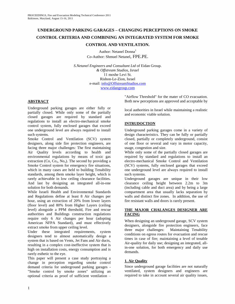
Smoke Layer Devices Specifications and location
Smoke Layer Devices measure the smoke layer
height descending from top end of measure point
(ceiling level) to bottom end (floor Level), and are
located throughout the egress routes.
Figure 12: Top Slanted View- Smoke Layer
measurement device Location – level (-4).
(Architectural Model version 2.0)
Pyrosim Model
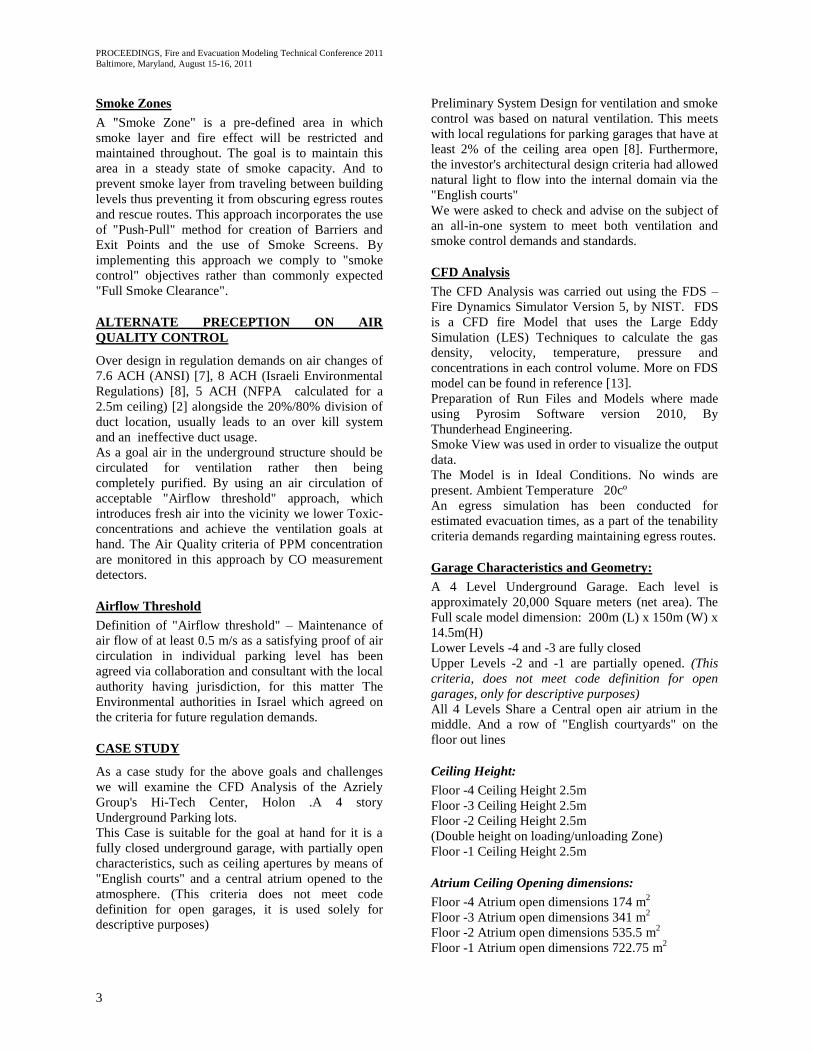
System Operation regiment
SCV System operates by Fire Zones.
For Run 02 – Level -4 System Activated
For Run 03 – Level -4 Zones 1 and 2 Activated.
Each fire zone has a separate Sprinkler grid.
On Sprinkler activation, SCV of Specific zone
commence its operation respectively.
Each SCV Shaft it governing a unique fire/smoke
zone
Figure 13: Top View- Smoke Zone, level (-4).
(Architectural Model version 2.0)
CFD Analysis Results and predictions
Evacuation analysis
In order to predict the egress times form level (-4) an
evacuation simulation has been carried out.
Model Basic Assumptions:
Parking level capacity – 160 vehicles.
Percentage of occupied vehicles in daily usage for
active business center – 40% max = 40 Vehicles.
Human Occupancy:
- 20 Vehicles – 2 passengers Per Vehicles
- 10 Vehicles – 1 passengers Per Vehicles
- 10 Vehicles – 3 Passengers Per Vehicles
- Total Occupancy : 80 People
Model Results – 70 seconds for complete egress to
safe refuge area.
This model calculates the movement time excluding
detection time, alarm time, pre-movement time and
response time. According to FDS simulation results,
sprinkler activation time for a car fire on level (-4) is
210 sec. At this point fire alarms sound and the
recognition/pre-movement time starts. This is the
period of time it takes for occupancies to investigate
regarding the nature of the alarm. In open areas, such
as a parking space, a fire would be visible in a short
period of time, therefore we predict a
recognition/pre-movement and response time to be
not grater then 60 seconds. Preceding this stage is the
actual egress time calculated in our simulation.
In order to maintain a safe margin on the actual
evacuation time we use a multiplier of 1.5 as a safety
factor. Thus the total time to evacuate to a safe refuge
area is calculated as following [1]:
Figure 14: Calculation of Evacuation Time
The Total Calculated Evacuation time is 495 sec =
8:15 minutes.
Run 01 – Fire only & Natural Ventilation
Smoke Detection Time: 54 sec
Heat Detection / Sprinkler Activation Time: 210 sec
Natural ventilation does not meet the codes,
regulations and tenability requirements neither for
smoke control nor ventilation goals and objectives.
It is used in simulation mostly to indicate a system
failure scenario.
EXIT
EXIT EXIT
EXIT
Smoke Layer
Measurement
Device
Zone 02
Zone 01 Zone 03
Zone 04
Detection
Time
Recognition/
Pre-movement Time
Response
Time
Movement
Time + + + ( )*1.5

PROCEEDINGS, Fire and Evacuation Modeling Technical Conference 2011
Baltimore, Maryland, August 15-16, 2011
8
Run 01 - Smoke Behavior in Level -4
Figure 15: Run01- Smoke behavior –Top & Side view
@ t=1 min Smoke Detection Time
Figure 16: Run01- Smoke behavior –Top & Side
view @ t=3:30min (Heat Detection Time)
Figure 17: Run01- Smoke behavior –Top & Side view
@ t=4:30min (Egress Start)
Figure 18: Run01- Smoke behavior –Top & Side view
@ t=5:40min (Egress End)
Figure 19: Run01- Smoke behavior –Top & Side view
@ t=8:15min (Safe Margin)
Run 02– Fire & Original SCV Design
Smoke Detection Time: 50 sec
Heat Detection / Sprinkler Activation Time: 277sec
Original SCV System Design does not meet the
tenability requirements for smoke control therefore
ventilation test are not preformed. Furthermore, fire
location on this run, was located on the opposite side
of the open atrium and differs between V1 to V2 of
the architectural model.

PROCEEDINGS, Fire and Evacuation Modeling Technical Conference 2011
Baltimore, Maryland, August 15-16, 2011
9
Run 02 - Smoke Behavior in Level -4
Figure 20: Run02-Smoke behavior –Top & Side view
@ t=1 min Smoke Detection Time
Figure 21: Run02-Smoke behavior –Top & Side View
@ t=3:30min (Heat Detection Time)
Figure 22: Run02-Smoke behavior –Top & Side view
@ t=4:30min (Egress Start)
Figure 23: Run02-Smoke behavior –Top & Side view
@ t=5:40min (Egress End)
Figure 24: Run02-Smoke behavior –Top & Side view
@ t=8:15min (Safe Margin)
Run 03– Fire & Redesigned SCV System,
Incorporating Smoke Zone for smoke control
criteria
Smoke Detection Time: 54 sec
Heat Detection / Sprinkler Activation Time: 210 sec
Redesigned SCV System meets the tenability
requirements for smoke control as defined in the
criteria for controlling smoke in one "Smoke Zone",
while keeping egress routes and accessibility for fire
rescue team.

PROCEEDINGS, Fire and Evacuation Modeling Technical Conference 2011
Baltimore, Maryland, August 15-16, 2011
10
Run 03 - Smoke Behavior in Level -4
Figure 25: Run03- Smoke behavior –Top & Side view
@ t=1 min Smoke Detection Time
Figure 26: Run03- Smoke behavior –Top & Side view
@ t=3:30min (Heat Detection Time)
Figure 27: Run03- Smoke behavior –Top & Side view
@ t=4:30min (Egress Start)
Figure 28: Run03- Smoke behavior –Top & Side view
@ t=5:40min (Egress End)
Figure 29: Run03- Smoke behavior –Top & Side view
@ t=8:15min (Safe Margin)
Run 03 - Visibility Slices in Level -4
(For illuminated Exit signs, scale: Red-30m-Blue 0m)
Figure 30: Run03- visibility slice, 2 m from floor
level - Top view @ t=1 min Smoke
Detection Time

PROCEEDINGS, Fire and Evacuation Modeling Technical Conference 2011
Baltimore, Maryland, August 15-16, 2011
11
Figure 31: Run03- visibility slice, 2 m from floor
level - Top view @ t=3:30min (Heat
Detection Time)
Figure 32: Run03- visibility slice, 2 m from floor
level - Top view @ t=4:30min (Egress
Start)
Figure 33: Run03- visibility slice, 2 m from floor
level - Top view @ t=5:40min (Egress
End)
Figure 34: Run03- visibility slice, 2 m from floor
level - Top view @ t=8:15min (Safe
Margin)
Run 03 - Temperature Slices in Level -4
Figure 35: Run03- temperature slice –Top view @
t=1 min Smoke Detection Time
Figure 36: Run03 - temperature slice –Top view @
t=3:30min (Heat Detection Time)
Figure 37: Run03 - temperature slice –Top view @
t=4:30min (Egress Start)
Figure 38: Run03 - temperature slice –Top view @
t=5:40min (Egress End)

PROCEEDINGS, Fire and Evacuation Modeling Technical Conference 2011
Baltimore, Maryland, August 15-16, 2011
12
Figure 39: Run03 - temperature slice –Top view @
t=8:15min (Safe Margin)
Ventilation CFD analysis
Based on redesigned SCV System for Run 03, a
ventilation simulation was carried out to check if it
meets the "Airflow Threshold" suggested and
authorized by national authorities as new criteria for
ventilation.
SCV system configured to supply half of its thrust for
ventilation usage; only 2 out of 4 fans are operational
in this case. A total of 115 m3/s = 4.14 ACH. Results
show that an "Airflow Threshold" of at least 0.5 m/s
is achieved throughout the domain. A problematic air
congested area exists at the boundaries of zone 2, this
issue was addressed in redesign suggestion by
installation of low power Jet fans.
Figure 40: Ventilation Run -Velocity slice @ 1.5m
from floor level –Top view @ t=10:00
min (scale red 1m/s – blue 0m/s)
CONCLUSION
In this paper we have suggested a change in
perception on smoke control criteria – "Smoke
Zones"; a new perception on ventilation criteria for
underground parking garages – "Airflow Threshold";
and an optional all-in-one design to meet all safety
goals and objectives according to codes and
regulations. These perceptions where portrayed by a
case study of a 4 story underground garage and have
been approved for usage under Israeli regulations by
the Fire and Rescue and Environmental Regulation
authorities.
Additional achievements in this area:
The utilization of an All-In-One system
design that meets all integrated
requirements.
Implementation of "Mode of Action" for
firefighting and rescue services, so they a
priory know the best approach for a fire
scenario.
Change in Fire and rescue authorities
misconception that smoke control and
smoke clearance are interchangeable
terminology. Where fire lies, smoke will be
present.
New criteria to be used for future system
design.
We would like to suggest our perception as a tool to
be used by other system designers when approaching
issues such as the ones portrayed in this paper.
REFERENCES
[1] SFPE Fire Protection Engineering Handbook,
fourth Edition.
[2] NFPA 88A, "Standard for Parking Structures",
National Fire protection Association, Quincy,
MA.2011.
[3] NFPA 92B, "Standard For Smoke Management
System In Malls, Atria, And Large Spaces",
National Fire protection Association, Quincy,
MA.2009.
[4] NFPA 101, "Life Safety Code Handbook",
National Fire protection Association, Quincy,
MA.2009.
[5] NFPA 204, "Standard For Smoke And Heat
Venting", National Fire protection Association,
Quincy, MA.2007.
[6] NFPA 502, "Standard for Road Tunnels, Bridges,
and other Limited Access Highways", National
Fire protection Association, Quincy, MA.2010.
[7] ANSI/ASHRAE Standard 62-1989, Ventilation
for Acceptable indoor Air Quality
[8] "Israeli Building Construction regulation",
Chapter H, 2009.
[9] Janssens, M., “Development of a database of
fullscale Calorimeter Tests of Motor Vehicle
PROCEEDINGS, Fire and Evacuation Modeling Technical Conference 2011
Baltimore, Maryland, August 15-16, 2011
13
Burns,” Report prepared for MVFRI by SwRI,
March 2008. www.mvfri.org
[10] Karati, M. and Ayari, A. (2001), "Ventilation
for Enclosed Parking Garages", ASHRAE
Journal, febuary 2001, 52-55.
[11] Kasuhiro, O., Norimichi, W., Yasuaki, H.,
Tadaomi, C. Ryoji, M., Hitoshi, M., Satoshi,O.,
Hideki,S., Yohsuke,T., Kimio,H., Yasumasa,M.
and Jinji, S.(2009), "Burning Behavior of Sedan
Passenger Cars", Fire Safety Journal, volume 44.
[12] Salvi, O., Lönnermark, A., Ingason, H., Truchot,
B., "eucker, R., Amberg, F., Molenaar, D. J. and
Hejny, H. (2010), "New Energy Carriers in
Vehicles and Their Impact on Confined
Infrastuctures – Overview of Previous Research
and Research Needs", Proceedings of the ISTSS
2010, Frankfurt am Main, Germany,17-19
March, 2010.
[13] McGrattan, Kevin B., Baum, Howard R., Rehm
Ronald G., Hamins, Anthony, Forney, Glenn P.,
Fire Dynamics Simulator – Technical Reference
Guide, National institute of Standard and
Technology, Gaithersburg, MD, NISTIR 6467.
January 2000).