underground car parks - arcelormittal
TRANSCRIPT

ArcelorMittal Sheet PilingArcelorMittal Sheet Piling
Guide Book for The Netherlands - 2018Underground car parks

This brochure is based on a report prepared in 2018 by Royal Haskoning DHV, a company based in the Netherlands, for ArcelorMittal Commercial RPS S.àr.l. It reflects the key findings from their assessment. However, ArcelorMittal added material (sketches and pictures), and edited parts of the original text, without changing the key findings. The original report from Royal Haskoning DHV is available on request.

Introduction 2
1. Design 3 1.1. Design approach 3 1.2. Sheet pile section 3 1.3. Steel grades 4 1.4. Optimization of the solution 4 1.5. Design software 4 1.6. Deflection / deformation 4 1.7. Vertical load bearing capacity 4 1.8. Corrosion 5 1.9. Coatings 5 1.10. Fire design 6 1.11. Connections between structural elements and the steel sheet pile wall 7 1.12. Footprint 8 1.13. Watertightness 8 1.14. Design examples 9
2. Construction 10 2.1. Sheet pile installation 10 2.2. Vibrations 10 2.3. Noise 10 2.4. Temporary supports 10 2.5. Working sequence 11 2.6. Watertightness 11 2.7. Construction time 11 2.8. Deformation monitoring 11
3. Operation & Maintenance 12 3.1. Maintenance 12 3.2. Watertightness 12 3.3. Coatings 12
4. Cost 13 4.1. Procurement 13 4.2. Installation cost 13 4.3. Sealing systems 13 4.4. Coatings 14 4.5. Cost (for budgeting purposes) 14
5. Sustainability 15
6. Risks 16
7. Alternatives 1 7
8. Conclusion 18
9. Projects in the Netherlands 19
10. References 20
Table of content

2
Over the last decades, cities have grown significantly. The consequence is a higher building density, and the scarcity of space on the surface. Although a change of mindset is taking place, in many European cities, mobility still relies predominantly on individual cars and its inherent problem: parking spots. Clearly, residents prefer public spaces, such as parks, over parking areas, so that underground car parks (UCP) in urban areas seem the perfect solution.
Nowadays, property development requires incorporating car parking lots. The most common options are underneath the building or as a separate structure next to the property, i.e. under court areas, drive ways, public gardens or parks.
Moreover, city centres become more pedestrian friendly, and in some cases car traffic is prohibited in specific zones. This new trend leads to the need for additional parking facilities around the outskirts of city centres. These parking facilities shall be well connected to the local road infrastructures and public transport, minimising the travel time from one point to another.
Developers and operators look for the most cost-effective solution, without compromising safety, security, comfort, and environmental impact. In most cases, a steel sheet pile wall is the solution that meets all these stringent criteria.
Typically, underground facilities are more expensive than those above ground, but on the other hand, they increase the value of the land, and save space for more socially valuable activities, such as gardens,… However, the design and operation of UCP needs to address specific challenges, such as air quality (ventilation) and fire resistance, which are less critical for parking facilities above ground.
Many UCP have been built around the world during the last 50 years, but still too many investors, architects and engineers are reluctant to consider this proven solution in their projects.
ArcelorMittal Sheet Piles contracted the renowned consulting engineering company Royal Haskoning DHV in the Netherlands to elaborate a guide book on underground car parks, with a special focus on the Dutch habits and customs. The guide book1) [a] provides an overview of the common practice in the Netherlands regarding design, installation and permanent application of steel sheet piles for underground car parks.
Introduction
The guide book includes also typical examples and some recent projects. It considers facilities in an urban environment in typical Dutch sub-soil conditions, e.g. soft soil down to the Pleistocene sand layer at 10-15 m with a high ground water table as representative for the western part of the country, as well as a sandier sub-soil for the eastern part of the Netherlands.
In the Netherlands, steel sheet pile walls are cost-effective for UCP with 1 to 4 levels, but the guide focuses on the most common structures, which have 2-3 levels.
For a 15 m deep wall (2-3 level UCP) in the Netherlands, a budget estimation for several alternatives is (without any liability)
A steel sheet pile wall is up to 50% more cost-effective than a secant pile wall.
1) The guide book does not address all the parameters in detail
90125
300
140170140
210
550
210250
0
100
200
300
400
500
600
Sheet pilewalls
(vibrating)
Sheet pilewalls
(pressing)
Diaphragmwalls
Secant pilewalls
(with steel casing)
Cutter SoilMix walls
Cos
t for
15
m lo
ng e
lem
ents
(€ /
m2 )
Cost comparison15 m long elements (€/m2)

3
1. Design
The design is done according to the Dutch guide book CUR 166 [b] and covers every aspect from design (step-by-step design process), installation and maintenance of sheet piles, anchoring and struts. The design section of CUR 166 is incorporated in the Dutch national annex of Eurocode 7 (NEN 9997 [c], available in Dutch only).
spreadsheets), but for the dimensioning calculations (step 6) several variations of the soil and water levels and stiffness of the soil are necessary.
The calculations are prescribed in NEN 9997 (Table 9d).
It is possible to transfer vertical loads from the floors and the roof to the sheet piles (see chapter 1.7).
The sheet pile section shall be checked for the different limit states specified in the code. These verifications are based on the partial safety factor design:
• the ultimate limit state (ULS) checks the global and local strength, fatigue and buckling,
• the displacements / deformations are checked in the service limit state (SLS).
The choice of a solution shall consider design, driveability and durability aspects. It is done based on European standards EN 1993-5 [d] and EN 12063 [e], and being a complex task, it should be performed by experienced engineers.
1.2. Sheet pile section
Hot rolled steel sheet piles are produced and delivered according to EN 10248 [f].
The Dutch market uses almost exclusively hot rolled Z-type sheet piles for permanent applications. However, a combined wall system may be required for UCP with 3 and 4 levels.
Note that according to the CUR 166, reduction factors shall be applied to the section properties of U-type profiles, therefore Z-piles are more cost-efficient.
EN 1993-5 defines a classification of the cross-sections, which depends mainly on the flange width and the steel grade of the section. For some classes, the plastic section modulus Wpl could be used instead of the elastic one Wel. Savings between 10 and 25% can be done when the design uses Wpl of a class 2 section.
Common practice is to follow the methodology described by CUR 166. It identifies 13 steps:
1. determine the normative design rules and regulations,
2. determine the characteristic values of the parameters,
3. determine the design values of the parameters,
4. select calculation scheme A or B,
5. calculate the minimum penetration depth,
6. dimension the sheet pile structure (calculations),
7. check bending moments,
8. check shear and normal forces,
9. check anchor and strut forces,
10. check deformations,
11. check other failure mechanisms,
12. check construction aspects,
13. verify the choices that have been made.
The determination of the minimum penetration depth (step 5) can be determined by simple calculations (manually or with
1.1. Design approach

4
1.3. Steel grades
if deflection, (local) buckling and fatigue are not governing the design. Higher steel grades can increase the resistance of the section by up to 30% (mill specification S 460 AP versus S 355 GP).
The material properties are standardized in EN 10248.
The most common steel grade in the Netherlands is S 355 GP (with a yield strength of 355 MPa). However, a higher steel grade such as S 430 GP could be much more efficient
1.4. Optimization of the solution
The key parameters to consider for the optimum choice are section modulus, steel grade, corrosion rates, driveability, durability and sustainability.
Generally speaking, lighter sheet piles with high yield strength are the most cost-efficient. Indeed, the slight increase of the cost of higher steel grades is by far offset by the savings on weight of the sheet pile.
1.5. Design software
Dutch design rules are implemented in design programs such as D-Sheet and Technosoft.
More sophisticated finite element programs (such as Plaxis and Diana) do not have built-in design calculations according to NEN 9997, and are less convenient in the initial design process.
D-Sheet is the most common design software in The Netherlands.
ArcelorMittal developed a free software program Durability which can be downloaded for free from the website to simplify the choice of a sheet pile wall based on EN 1993-5.
1.6. Deflection / deformation
The allowable deflection of the wall will depend on the acceptable deformation and settlements close to the construction pit. CUR 166 mentions as an example the allowable bending of a permanent sheet pile wall (in view) at 1/200 of the maximum height to be reached in all construction phases, with a maximum of 50 mm. This requirement is normally used by the Dutch Rijkswaterstaat2).
One of the critical design criteria is the settlement caused by wall deformation, especially in urban areas where the buildings have already been subjected to some level of deformation. From analyses, an estimated value can be determined for the expected deformation due to steel sheet pile installation and operation.
However, when total deformations are defined one shall pay attention to other (enabling) works that precede the steel sheet pile installation such as the re-positioning of cables and sewage lines. For these works, trenches may be required which are hardly
ever provided with appropriate measures to limit soil deformation. It is common that these works already initiate a significant part of the maximum allowable deformation.
A method that is used in the Netherlands to determine the potential damage in buildings is the Limiting Tensile Strain Method (LTSM), an analytical method, based on observations, to predict the degree of possible settlement damage on buildings. This method assumes the full transfer of differential ground movements to the adjacent building, neglecting soil-structure interaction effects. It can be used as a simple tool for quick damage classification, based on the type of building, the geometry and characteristics of the construction pit. The methodology was originally derived for tunnels and has been adapted for construction pits, and therefore also for sheet pile walls that are used as part of the permanent structure. The method is particularly suitable for masonry constructions and to a slightly lesser extent for frameworks.
1.7. Vertical load bearing capacity
The bearing capacity of a sheet pile wall is mainly derived from wall friction in sand layers. It is preferably determined on the basis of effective stresses against the wall, taking into account bending of the wall, as well as the active and passive ground wedges.
Box piles (CAZ) inserted in the sheet pile wall in a specific pattern increase the bearing capacity of the retaining wall (see Figure 1). The box piles may be longer than the standard AZ sheet piles, adding toe resistance through a plugging effect.
Fig. 1. Combination of an AZ sheet pile wall with CAZ box-piles to increase vertical bearing capacity
2) The Rijkswaterstaat is part of the Dutch Ministry of Infrastructure and Water Management, and responsible for the design, construction, management and maintenance of the main infrastructure facilities in the Netherlands.

5
Fig. 2. Capping beam with typical reinforcing bars (based on the German National Technical Approval)
ArcelorMittal developed a simplified method for the design of a concrete capping beam capable of transferring high vertical and horizontal loads from a superstructure into the steel sheet piles. This method was validated by the German DIBt3),
who granted a German National Technical Approval in 2011 (latest revision: 2017) [g]. The design calculations can be done with the free software VLoad.
1.8. Corrosion
Steel corrosion is a natural phenomenon. Generally speaking, the loss of steel thickness in a natural soil is rather small, but it must be taken into account for maritime structures, unless a protection method is used to prevent steel from corroding.
The loss of steel thickness of unprotected steel can be estimated from EN 1993-5 (Tables 4.1 and 4.2). Corrosion rates depend on the surrounding media and the design lifetime.
The Dutch ROBK - Richtlijnen voor het ontwerpen van betonnen kunstwerken [h] refers to the CUR 166 for the level of corrosion for different durations, soil and water types. For sheet piles with a design life of 50 years, that have been placed in undisturbed clean soil, as well as for fresh groundwater, the expected loss of steel thickness is 0.60 mm (on one side). For more aggressive soils such as peat, this value can increase to 1.75 mm.
The most common protection systems are coatings. Alternatively, an additional thickness of the steel sheet piles can be considered.
This sacrificial thickness is most commonly used in the Netherlands because the other systems are less reliable and result in higher maintenance costs. Anyway, some architects prefer to apply a coating to a parking facility for aesthetic reasons, even when not required for design purposes. In that case, coatings are usually applied only on the visible side of the wall, from top to approximately 50 cm below the excavation level, respectively to the upper level of the bottom floor.
Finally, a concrete cover may be an option, as well as cathodic protection, but the latter is only efficient in water. Galvanization is an alternative for the atmospheric zone, but it is not cost-effective, and the length of galvanized sheet piles is limited (technical constraints).
1.9. Coatings
Coatings can be used for durability reasons, but most often in UCP, they are applied to enhance the aesthetical aspect of the wall.
Coatings are usually applied at the factory or after the sheet piles have been driven into the ground. The advantage of applying the coating at the workshop is the quality since the coating is applied under fully controlled conditions. The disadvantage relates to damage during transport and installation. Repair works after installation should be foreseen in the tender documents.
3) DIBt: Deutsches Institut für Bautechnik. Berlin. Germany.
It is recommended to use a system based on EN ISO 12944 [i]. Several systems exist, with a service life of 15 – 20 years, but no manufacturer will give a guarantee for more than 7 years.
Typically, a 2 or 3-layer system is adopted comprising a primer (60 – 70 μm), an intermediate layer (150 μm) and a top coat (150 μm epoxy or polyurethane).

6
There is no underground parking facilities’ specific regulation regarding fire. It must comply with the Bouwbesluit (Building Decree). A parking garage has, in most cases, a fire safety requirement of 60 minutes for the main load bearing structure. The design fire is in principle following the “standard” fire curve but the “natural fire” is also often used. The latter is more realistic when the parking facility has been provided with a suitable fire detection and a sprinkler system.
The Dutch recommendations Richtlijnen Ontwerp Kunstwerken (ROK, revision 1.4) [j], are applicable to all structures for the Rijkswaterstaat, but not by definition for other entities. Regarding the design of permanent steel sheet piles, it states following (free translation of an excerpt of the ROK):
Temperature requirements for steel sheet piles:
When using permanent steel sheet piling, it must be demonstrated that the construction can be completely repaired after the fire, according the prescribed fire curve, has occurred. For steel sheet piling, this requirement is deemed to be satisfied if it has been demonstrated, arithmetically or by means of tests, that the temperature in the sheet piling remains below 250°C. If it is demonstrated that the permanent additional deformations as a result of temperature increases do not have an adverse effect on the aesthetic appearance (including flatness), the usability and the safety of the structure and the environment after the fire, then a maximum temperature of 400°C is permissible.
Note that according to the TNO report Exploratory research into the cooling effect of groundwater on steel sheet piles, the presence of sand and / or clay does not allow the assumption of a cooling effect of groundwater behind the sheet pile.
Besides, based on NEN-EN 1993-1-2 [k], Table 3.1, a significant loss of resistance of steel occurs above 400°C.
There are several design approaches to the load case fire. The standard ISO fire curve is in ArcelorMittal’s opinion too conservative, and we propose to use a natural fire curve which can be assessed based on simplified, but realistic, assumptions. The shape, volume and ventilation of the structure, as well as the amount of flammable materials (objects) inside the structure, will determine the shape of the natural fire curve.
In case bare sheet piles are not able to resist the fire load case, solutions to increase the fire resistance consist in protecting the steel surface from reaching high temperatures, for instance by covering the surface with a concrete finish, with insulating panels and/or fire protection boards, with insulating coatings or with a masonry.
More details can be found in ArcelorMittal’s Fire design brochure [l] and in Figure 3.
a. Fire resistant coatings c. Fire resistant brick wall in front of the wall
e. Continuous concrete wall
Fig. 3. Protection of the steel surface in case of fire
b. Fire resistant boards
d. Concrete panels inside the pans
1.10. Fire design

7
a. Horizontal slab on a concrete beam b. Horizontal slab on a steel support
a. Impervious connection with bottom slab, solution 1 b. Impervious connection with bottom slab, solution 2
Fig. 4. Connection sheet pile wall - horizontal slabs
Fig. 5. Connection sheet pile wall-bottom slabs (watertightness)
1.11. Connections between structural elements and the steel sheet pile wall
The connection between the sheet pile wall and the structural elements of the parking facilities, i.e. floor slab, intermediate floor and roof slab can be executed as either stiff or hinged.
The bottom slab is generally stiff, and at this interface special attention shall be given to the watertightness. More details on such connections can be found in the brochure ‘Impervious steel sheet pile walls’ [m]. The connection between the sheet pile wall and intermediate floors is normally hinged, whereas the connection between the sheet pile wall and the roof slab, stiff or hinged and watertight.
Since the groundwater table is quite often near the surface, the UCP will be susceptible to water ingress, and especially so at the interface between the sheet piles and the floor / roof slab.
The floor, roof and/or any intermediate floor slab can, in addition to bearing the surcharge loads from traffic or static loads, also function as a horizontal strut for the sheet pile wall. Failure of a slab would therefore jeopardise the structural integrity of the whole (or part of) the structure.

8
b. Steel sheet piles for temporary use, pulled-out after execution of concrete structure
c. Steel sheet piles for temporary use, stay in place after execution of concrete structure
1.13. Watertightness
Water inside the underground car park facility can have several origins, some of which have a relation with the retaining system. Steel sheet piles are per se 100% watertight, and water seepage can only occur through the interlocks or through the joint between the sheet piles and the floor slab (groundwater) and/or the roof slab (precipitation).
In most cases, some leakage can be accepted (from a structural point of view) but can be unwanted from an aesthetic and operative perspective. It is recommended to install a light drainage system in case the interlocks are not seal-welded.
Acceptable leakage quantities could be derived from EN 1992-3.The most efficient method for reducing the risk of seepage is the welding of the joints from the bottom to the top of the exposed area. However, seal-welding is a relatively time-consuming and expensive method.
ArcelorMittal developed several sealing systems to reduce the seepage through the interlocks.
The water resistance and leakage rates of the sealing system have been tested in-situ based on a new concept that classifies the performance of the sealants. More details can be found in ArcelorMittal’s dedicated brochure [m].
Fig. 7. Sealing system Akila®
a. Steel sheet piles for temporary and permanent use (gain in surface)
1.12. Footprint
Steel sheet pile walls are mostly installed following a rectangular or a circular shape, but they are very flexible, so that any irregular shape is feasible.
The use of steel sheet piles as the permanent retaining structure leads to an optimization of the valuable ground surface.
No space is lost for temporary retaining structures in which the permanent structures is executed. For instance, with cast in-situ reinforced concrete structures built inside an excavation pit using a temporary retaining wall, a lot of valuable space is lost inside the excavation (see Figure 6).
Fig. 6. Footprints of different execution alternatives

9
1.14. Design examples
The guide contains two basic examples with typical cross-sections:
• 2-level in clayey and sandy layers with high water table,
• 3 level UCP in sandy layers.
Two installation methods have been considered: excavation in the dry and excavation in the wet (with a concrete bottom slab poured underwater). See the guide for more details on the execution phases.
Fig. 8. Design examples: cross-sections
Table. 1. Results for the 2 cross-sections
Fig. 9. Results for the 2-level UCP: phases 4 and 7
The first two sets of bending moments, shear forces and deformations are presented for the 2-level parking facility. The first set shows the situation after the excavation works, with one strut just below ground level, the second set shows the final situation after installation of the parking floors.
Figure 9 shows the values for the presented step complemented with the envelope of values from all steps.

10
2.2. Vibrations
Installation of steel sheet piles in Dutch soils is usually quite simple and very fast. The main challenge for an excavation procedure is the dewatering and the temporary strut system.
2. Construction
2.1. Sheet pile installation
Mobilisation routes to the parking facility location shall be considered when defining the selected equipment, especially on confined locations in old city centres.
For the installation of steel sheet piles in an urban environment, the most common technique is the high-frequency vibratory pile drivers, preferably with variable moments to reduce the risk of soil resonance, and sheet pile presses.
They can be installed by impact driving, vibratory driving or pressing, optionally combined with water-jetting and/or pre-drilling. The selection of the most appropriate methodology depends on the soil parameters, sheet pile type and characteristics, required depth of the wall, requirements regarding vibrations, noise and deformations, available construction space for the installation of the sheet piles including head room, ….
Vibratory driving, as well as impact driving leads inevitably to vibrations in the ground. In adjacent buildings, some types of vibrations may be perceived as uncomfortable to its occupants.
The vibrations may result in soil deformations, leading to damage to pavements, (permanent) architectonic or structural damage of buildings, buried utilities,…
In cases where the vibration levels are deemed unacceptable, switching to pressing equipment is the preferred installation option, even though pressing is more expensive, and not so fast.
The publication SBR-Trillingsrichtlijn A: Schade aan bouwwerken 2017 [n] (available in Dutch language only) deals with the way in which vibration measurements can be carried out on structures, and the way in which the results of the vibration measurements have to be processed and assessed.
Note that the presence of obstacles in the ground can lead to instant increase of vibrations in the surroundings; underground obstacles are quite common in dense urban areas.
2.3. Noise
Noise can also be perceived as uncomfortable by the neighbours. The use of special silencing systems applied to the piling equipment can reduce the propagation of noise through the air. Although vibratory hammers may produce higher noise levels at regular intervals, they may be preferred, because the installation of the
wall can be faster, and hence the nuisance occurs during a shorter period.
However, close to hospitals and buildings with more sensitive residents, such as health care centres for seniors, pressing should be preferred.
2.4. Temporary supports
If the geometry of the lay-out allows it, the preferred option is to use temporary struts that can be removed later during the erection of the parking deck structure, so that the decks will take over the loads from the temporary supports.
Anchors are the alternative to struts; they can have a temporary or a permanent function. Anchors may also be preferred in case the geometry (footprint) of the facility does not allow for struts.
Note that the use of (permanent) anchors may be restricted due to property rights. It is advised not to leave anchors in the ground if they extend outside of the property line.

11
2.5. Working sequence
An underground facility can be realised using two methods, the conventional bottom up and the alternative top-down (wall-roof method).
In the conventional bottom-up method, first the sheet piles are installed, then the soil is excavated, and the struts / anchors installed concurrently to the excavation works. The concrete bottom slab can be casted under water (non-reinforced) or in the dry (reinforced concrete). From there, the parking structure is built from the bottom of the excavation up to the top.
The alternative method top-down also starts with the installation of the sheet piles, followed by an initial excavation to cast the concrete roof slab, which then functions as a strut during the further excavation phases. This method avoids the use of intermediate temporary strut layers, but requires the execution of deep foundations for the columns inside the wall perimeter.
a. Steel sheet piles & piles for foundations installed b. Excavation to level slightly below top strut c. Installation of top strut, followed by excavation to level slightly below second strut
e. Execution of permanent slab, followed by removal of lower strut
f. Execution of permanent slab (acting as strut) and removal of top strut
Fig. 10. Bottom-up construction method (simplified phasing)
d. Installation of bottom strut, excavation under water, followed by bottom slab poured under water
2.6. Watertightness
Sealing systems for the interlocks may be used to reduce water seepage through the interlocks during the construction period, and simplify the welding of the free interlocks after installation.
In case seal-welding is chosen, double Z piles can be supplied with a common interlock seal-welded at the factory.
2.7. Construction time
Steel sheet piles can be installed very rapidly using vibratory hammers (depending on the soil). In case the sheet piles need to be
installed using an hydraulic press, the installation time will be longer, but still faster than most of the alternative retaining structures.
2.8. Deformation monitoring
Deformation of the sheet pile walls should be monitored by either automatic or manual systems. Additionally, surface inspections
around the circumference of the facility may indicate areas of concern where too large deformations may occur.
One or more accesses, or openings in the roof slab, allow for excavation and logistics. Additionally, the execution of the superstructure can be done in parallel to the excavation below ground, so that overall, the building may be finished earlier than with the conventional bottom-up method.
The main advantage of the bottom-up is the ease of work. Full access with cranes allow for a simple construction, especially when the interior of the facility consists of large and heavy elements (columns, beams and floor plates).
The main advantage of the top-down method is the speed of execution and the fact that from the moment that the roof slab has sufficient strength, all further activities will take place under that roof. Hence, in case of a UCP below a square or a road, the space above the ground level can be opened to traffic / parking much earlier.

12
3. Operation & Maintenance
3.1. Maintenance
Similar to all permanent civil works, two types of maintenance can be identified for permanent structures:
• corrective maintenance: after some level of failure has occurred,
• preventive maintenance: done after a certain pre-determined period (time), number of applications or (pre-failure) state.
The selection of the appropriate maintenance strategy depends on several variables:
• structural sensitivity,• economic loss in case of failure,• cost of maintenance,• cost of repair after failure.
3.2. Watertightness
In case too much water seeps through the interlock’s sealing system, it might be necessary to seal-weld some of the interlocks.
If water seeps through the connection concrete slab / sheet pile, injection of grout is an option.
3.3. Coatings
Coatings require maintenance, such as cleaning and repair in case of damage. Maintenance of surface coatings consists usually in renewing the coating at regular intervals, say 15-25 years. The actual frequency for re-applying a coating will, amongst other,
depend on the quality and function of the coating, i.e. replacement interval of a coating for aesthetic reasons will differ from the coating used for anti-corrosion or for fire protection.

13
4. Cost
Investors and operators should consider the sustainability of the project, which defines financial, environmental and social aspects.
From the financial point of view, the key factor is the total cost of the structure. It encompasses all the costs incurred during the service life of the structure:
• land,
• financial burdens (loans),
• design,
• execution,
• operation & maintenance,
• dismantlement,
• disposal,
as well as the benefits that can be expected at the end of life from
• re-use,
• recycling of materials.
The investor should choose the most sustainable solution, preferably the one with the lowest environmental impact (see chapter 5). Fact is that the cheapest solution is not necessarily the most sustainable one.
Note: additional criteria to compare alternatives are the quality and durability of the products / solutions.
4.1. Procurement
Unlike most of the alternatives, the cost of a steel sheet pile wall depends highly on the procurement cost of the sheet piles. The transport of sheet piles requires trucks that can negotiate the length of the sheet piles, and a crane for lifting them at the construction site for temporary storage.
Further additional costs relate to the supports (anchors, walings,…), corrosion protection, special piles (fabrication), sealing systems.
4.2. Installation cost
The cheapest and most used option in The Netherlands is vibratory driving. The cost of pressing is at least twice the cost of vibratory driving.
The installation usually requires a crane for lifting and driving the sheet piles to the required depth.
The cost per driven m2 varies significantly with the soil conditions.
The rate of installation depends also a lot on soil conditions and pile length: from 5 double AZ piles up to 20 double piles per day.
4.3. Sealing systems
This requirement will have a slight influence on the total cost of the retaining wall. Seal-welding is most often used when the levels are below the groundwater table. The cost factor between a simple
filler, such as a bituminous product, and the seal welding is around 5.0, whereas the efficient sealing system Akila® is only around 2.5 times more expensive.

14
4.4. Coatings
Depending on the coating system recommended for an UCP, the cost per m2 of coating applied at the factory varies from 25 to 50 €/m2 (area of the section). Transport, handling and installation
4.5. Cost (for budgeting purposes)
The cost for a permanent steel sheet pile wall with a length of 15 m that is driven to the required depth varies between 90 and 140 €/m2 (installation with a vibratory hammer).
In case a jack / press is used, the estimated additional cost is 35 to 70 €/m2.
For longer sheet pile walls, the estimated additional cost is 12 to 25 €/m2.
These cost indications exclude anchors and/or struts, coatings, sealing systems, etc.
This is only a range, and can vary significantly based on soil and groundwater conditions.
These costs do not consider maintenance and dismantling costs, nor benefits from re-use or recycling after the service life.
of coated piles require more care, so that a coating will lead to a slight increase of the installation costs.

15
5. Sustainability
One of the advantages of steel sheet piles is their suitability for re-use (several times) and recyclability. Steel sheet piles can in principle be reused after their already long service life in underground car parks. If not reused, they will be recycled. They have a high recovery rate, so that up to 100% of recycling is technically feasible.
The sustainability of materials, products and civil works can be valued using the Dutch Milieu Kosten Indicator MKI (Environmental Cost Indicator). The MKI covers 11 environmental effect categories, including climate change (CO2-eq), deterioration of the ozone layer (CFK-11 eq), human toxicity (1.4-DCB eq) and depletion of natural resources (Sb eq). The emissions associated to each environmental effect category are converted from equivalent emissions (midpoint scores) to environmental cost (endpoint scores) using weighting factors. These weighting factors represent the highest allowable cost level per unit emission, and vary from e.g. 30 €/kg CFK-11 eq to 0.05 €/kg CO2 eq.
While greenhouse gas emissions (in CO2 eq) are often used as an indicator for the environmental performance of materials, products and civil works, it is not necessarily a good proxy. For example, a coating can have small impact on climate change but high aquatic ecotoxicity (1.4-DCB eq), which contributes significantly to the endpoint score of the MKI.
The MKI is increasingly incorporated in public procurement as an award criterion. For example, the Dutch railway infrastructure provider ProRail and the Dutch government either set minimum sustainability requirements or give a discount (credit) to proposals with a low MKI.
The determination of the MKI can be done with DuboCalc, a software program that contains an extensive database of (different components of) civil structures. The MKI in DuboCalc normally covers all phases of the life cycle, including transport, construction and end of life. When considering the whole life cycle of steel sheet piles, the impacts of transport, installation and maintenance are generally small compared to the primary production of the steel sheet piles.
Aside from DuboCalc, Life Cycle Analysis (LCA) software programs such as SimaPro and GaBi can be used to calculate the environmental impact of products and processes. When comparing the environmental performance of two (or more) identical products, it is recommended to use Environmental Product Declarations (EPD) of the manufacturers based on the European standard EN 15804 [o]. This guarantees that the environmental impact assessment of a product is conducted following an international standard (i.e. ISO 14025 [p]), and
contains comparable information that is independently verified (peer-reviewed).
The environmental cost is relevant from a Corporate Social Responsibility point of view, and is gaining more widely acceptance as part of the selection criteria for the award of contracts.
The Aanbestedingswet (Public Procurement Act) applies to all public entities in the Netherlands.
The 2012 version of the Public Procurement Act version 2012 added the possibility to award on the basis of ‘lowest cost calculated on the basis of cost effectiveness such as the life cycle costs’. Two other award criteria remained unchanged: the best price-quality ratio, and the lowest price.
The Public Procurement Act 2012 therefore defines the life cycle costs (LCC), as follows:
a) costs borne by the contracting authority or other users, such as acquisition, running costs, maintenance costs and disposal costs,
b) costs attributed to external environmental impacts related to the product, service or work during the period life cycle, provided their monetary value can be determined and controlled.
Projects tendered under the Public Procurement Act may include the environmental cost assessment. Whether this is indeed required depends on the organisation that defines the selection criteria.
Below is a non-exhaustive inventory of possible award criteria:
• (construction) process,
• performance / quality,
• service,
• functionality,
• technique,
• aesthetics / experience value,
• social,
• use,
• sustainability,
• profitability,
• service life,
• secondary investments,
• cost.
However, the interpretation of these criteria may be quite abstract and subjective.
16
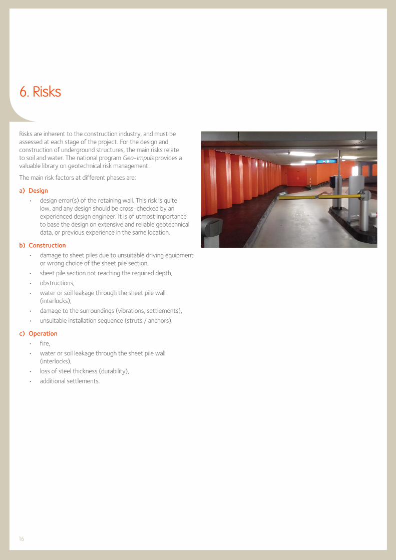
6. Risks
Risks are inherent to the construction industry, and must be assessed at each stage of the project. For the design and construction of underground structures, the main risks relate to soil and water. The national program Geo-Impuls provides a valuable library on geotechnical risk management.
The main risk factors at different phases are:
a) Design
• design error(s) of the retaining wall. This risk is quite low, and any design should be cross-checked by an experienced design engineer. It is of utmost importance to base the design on extensive and reliable geotechnical data, or previous experience in the same location.
b) Construction
• damage to sheet piles due to unsuitable driving equipment or wrong choice of the sheet pile section,
• sheet pile section not reaching the required depth,
• obstructions,
• water or soil leakage through the sheet pile wall (interlocks),
• damage to the surroundings (vibrations, settlements),
• unsuitable installation sequence (struts / anchors).
c) Operation
• fire,
• water or soil leakage through the sheet pile wall (interlocks),
• loss of steel thickness (durability),
• additional settlements.

17
7. Alternatives
The main construction alternatives to steel sheet piles (including steel combined walls) are secant piles, cutter soil mix walls (CSM) and diaphragm walls.
For up to 4 levels below ground, steel sheet piles are the most cost-efficient, and the execution of a diaphragm wall is the most expensive.
a) Diaphragm walls
The advantage of a diaphragm wall is that installation is possible without vibrations, so less risk of damage to the surrounding, combined with a high vertical and horizontal bearing capacity. Therefore, it is particularly of interest for multi-level parking underneath high-rise buildings where the diaphragm walls are part of the foundation.
The continuous diaphragm wall is a structure formed and cast in a slurry trench. The trench excavation is initially supported by either bentonite or polymer based slurries that prevent soil incursions into the excavated trench. The term diaphragm wall refers to the final condition when the slurry is replaced by tremied concrete that acts as a structural system either for temporary excavation support, or as part of the permanent structure. It has a high bending stiffness, resulting in limited deformation of the ground behind it. Diaphragm walls can be installed to large depths (up to 120 m), even when very compact soil layers or rock must be penetrated. However, it is difficult to achieve full watertightness of the wall, and a diaphragm wall cannot be reused. Diaphragm wall construction requires the use of heavy construction equipment with reasonable headroom, site area, and considerable mobilisation costs.
The unit cost for 15 m deep diaphragm walls vary between 300 and 550 €/m2, for deeper diaphragm walls the unit rates will (for up to 30 m deep) increase with 10 % to 15 %. These ranges only cover the activities related to the construction of the diaphragm walls (direct cost).
It shall be noted that the unit rate for the disposal of the excavated muck varies between 9 and 20 €/m3.
b) Secant pile walls
Secant pile walls are formed by intersecting reinforced concrete piles. The secant piles are reinforced with either steel rebars or with steel beams, and are constructed by either drilling under mud or augering. Primary piles are installed first with secondary piles constructed in between primary piles once the latter gain sufficient strength. Pile overlap is typically in the order of 8 cm. In a tangent pile wall, there is no pile overlap as the piles are constructed flush to each other.
A secant pile wall can also bear vertical loads. It can be executed with low levels of vibration and noise. Installation to large depths
is possible, even if very solid soil layers are present. The horizontal deformations are small. However, verticality tolerances are usually hard to achieve for deep piles. Complete watertightness is difficult to accomplish, especially at the joints. Anchoring at a level below the top can cause problems, except in the case of struts and girders.
The unit cost for 15 m deep secant pile walls varies between 70 and 140 €/m2 for the auger pile, up to 140 to 210 €/m2 when the pile is provided with a steel casing. For deeper secant pile walls the unit rates will (for up to 30 m deep) increase by approximately 25%.
c) Cutter soil mix walls
Cutter soil mix walls are constructed by mixing and partly replacing the in-situ soils with a stronger cement material. Various methods of soil mixing such as mechanical, hydraulic, with and without air, and combinations of both types have been used widely in Japan for about 20 years. Soil mixing has been used for many temporary and permanent deep excavation projects.
Mechanical soil mixing is performed using single or multiple shafts of augers and mixing paddles. Unreinforced soil mix walls are typically used as hydraulic barriers. In some cases they are also used as retaining walls, especially if constructed as massive blocks or other element types. In such a case, the tensile strength of the soil mix is typically the one controlling the structural soil mix wall capacity. If a soil mix wall is reinforced with a steel beam, then it is typical to calculate the wall capacity using only the steel beam strength and in essence, consider the soil mix as lagging.
For the cutter soil mix walls, the unit cost for 15 m deep walls typically varies between 170 and 250 €/m2.
d) Cost comparison
The cost of each solution can vary significantly by project, and depends mainly on soil conditions and other local parameters. Below table can be used for general information only and is based on the consulting engineering firm’s past experience. However, it shows general trends. For instance, it is evident that within the assumptions that were made in the report, the execution of diaphragm walls is much more expensive than a steel sheet pile retaining wall.
Cost of 15 m deep retaining wall
Steel sheet pile walls (installed with vibratory driver) 90 - 140 €/m2
Diaphragm walls 300 - 550 €/m2
Secant pile walls (with steel casing) 140 - 210 €/m2
Cutter soil mix walls 170 - 250 €/m2
18
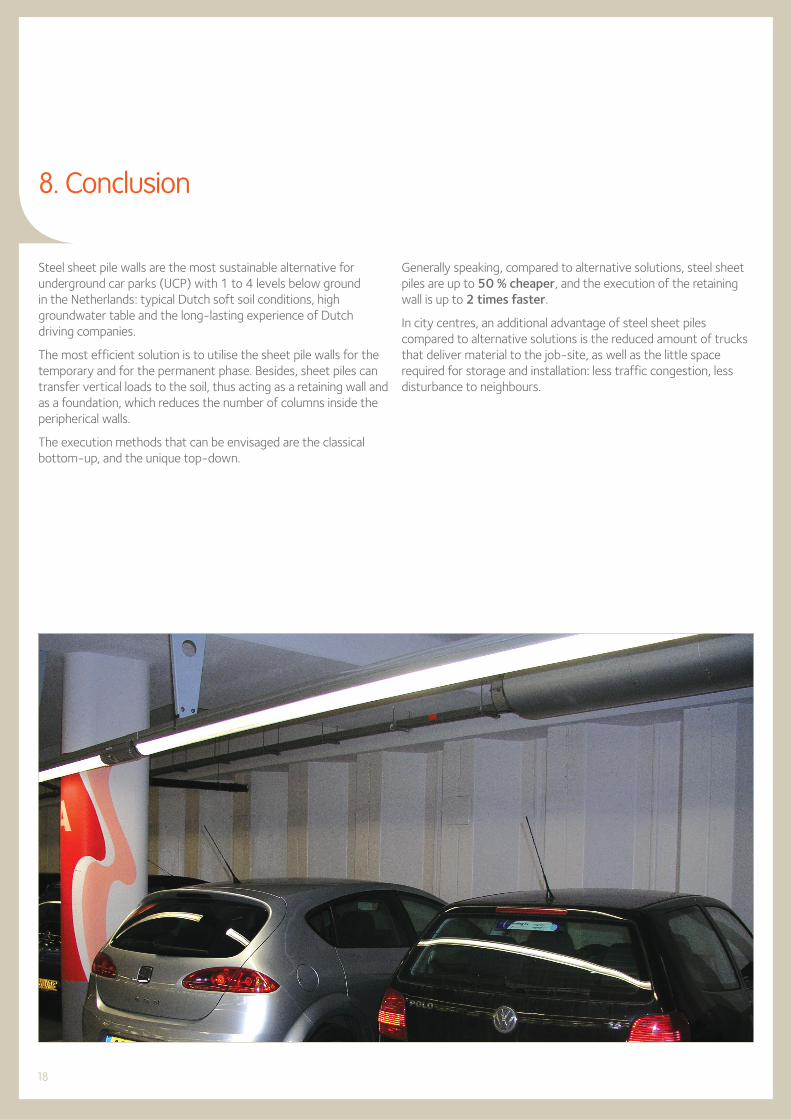
8. Conclusion
Steel sheet pile walls are the most sustainable alternative for underground car parks (UCP) with 1 to 4 levels below ground in the Netherlands: typical Dutch soft soil conditions, high groundwater table and the long-lasting experience of Dutch driving companies.
The most efficient solution is to utilise the sheet pile walls for the temporary and for the permanent phase. Besides, sheet piles can transfer vertical loads to the soil, thus acting as a retaining wall and as a foundation, which reduces the number of columns inside the peripherical walls.
The execution methods that can be envisaged are the classical bottom-up, and the unique top-down.
Generally speaking, compared to alternative solutions, steel sheet piles are up to 50 % cheaper, and the execution of the retaining wall is up to 2 times faster.
In city centres, an additional advantage of steel sheet piles compared to alternative solutions is the reduced amount of trucks that deliver material to the job-site, as well as the little space required for storage and installation: less traffic congestion, less disturbance to neighbours.

19
9. Projects in the Netherlands
a) UCP De Prins, Breda
The parking facility De Prins is part of a larger development that includes offices and apartments. The facility is fully underground and consists of 2 parking levels, each with an area of 6400 m2. The perceived safety of the UCP was improved through the realisation of day-light access along the borders of the facility.
b) Markt garage near the Koepoort, Delft
The parking is close to the historic centre of the city of Delft, has 2 levels and a capacity of 367 cars. The lack of space at the entrance provided some challenges to the designers. The result is a solution where the incoming and out-going vehicles use a continuously curved ramp. On top of the facility are 15 small houses with gardens, a public road (class 45) and some bicycle paths.
c) Apartment buildings, Leyweg, The Hague
As part of the development of several apartment buildings, an UCP was built at the Leyweg in The Hague. The parking was built according to the polder principle: the sheet piles for the excavation remain in the ground and penetrate a clay layer at a deeper level. The groundwater level is regulated through continuously pumping, so that the bottom level of the basement does not need a watertight slab, which is cost efficient.
d) Underground car park, Markthal, Rotterdam
The parking facility provides for some 1100 parking spots. The construction pit for the parking facility underneath and next to the Markthal in Rotterdam was designed to become the permanent structure. The water and ground retaining walls are wide steel sheet piles (AZ 14-770 x 20 m) and tube piles (ø 1020 mm x 25 m). The steel tubes bear also vertical loads.
The concrete beams of the basement floors act as struts to support the peripheral walls. The bottom floor, which resists to the vertical groundwater pressure, is made of 1.35 m thick underwater concrete and was reinforced to avoid a standard construction floor. All these measures resulted in fewer construction phases, and therefore less risk for deformations.
e) Parking Facility Scheepmakershaven, Rotterdam
This is one of the deepest UCP in the Netherlands: 4-level car park with a length of 300 m, a depth of 14 m, and accommodates 623 parking places. The retaining system consists of steel combi-walls which comprise 1220 mm diameter steel tubes with intermediary AZ sheet piles. The joints between the tubular and sheet piles have been welded down to a depth of 15 m.
f) Raaksproject, Haarlem (2006)
The first phase of the Raaksproject included a 2-level, 200 parking-space carpark P2, and was launched in September 2006. Construction of the large, 3-level public car park P1, with a capacity for 1000 vehicles, right next to the smaller car park, started in January 2007 and was commissioned in May 2010.
Fig. 11. Raaksproject, Haarlem. Cross-section

20
10. References
[a] Steel Sheet Piles for Underground Car Parks (UCP). Royal Haskoning DHV NL. Unpublished report prepared for ArcelorMittal. 2018
[b] CUR 166. Damwandconstructies, 6e druk. CUR. 2012
[c] NEN 9997-1:2012. Geotechnisch ontwerp van constructies - Deel 1: Algemene regels. NEN. 2012
[d] EN 1993-5: 2007. Eurocode 3. Design of steel structures. Part 5: Piling. CEN. 2007
[e] EN 12063: 1999. Execution of special geotechnical work. Sheet-pile walls. CEN. 1999
[f] EN 10248-1: 1995. Hot Rolled Sheet Piling of Non Alloy Steels. Part 1: Technical delivery conditions. CEN. 1995
[g] Allgemeine Bauartgenehmigung Nr. Z-15.6-235. Stahlbetonholm mit Schneidenlagerung zur Einleitung von Vertikal- und Horizontalkräften in Stahlspundwandbohlen der Firma ArcelorMittal nach DIN EN 1992-1-1 mit DIN EN 1992-1-1/NA. DIBt. 2011 - 2017
[h] ROBK - Richtlijnen voor het ontwerpen van betonnen kunstwerken (versie 6). Rijkswaterstaat Bouwdienst - NL. 2002
[i] EN ISO 12944: Paints and varnishes - Corrosion protection of steel structures by protective paint systems - Parts 1 – 9. 2017
[j] Richtlijnen Ontwerp Kunstwerken (ROK, revision 1.4). Rijkswaterstaat - NL. 2017
[k] NEN-EN 1993-1-2: 2011. Eurocode 3: Ontwerp en berekening van staalconstructies - Deel 1-2: Algemene regels - Ontwerp en berekening van constructies bij brand. NEN. 2011
[l] Underground car parks. Fire resistance. ArcelorMittal. 2012
[m] Impervious steel sheet pile walls. Design & practical approach. ArcelorMittal. 2017
[n] SBR-Trillingsrichtlijn A. Schade aan bouwwerken 2017 (Damage to buildings 2017). SBRCURnet. 2018
[o] EN 15804: 2012: Sustainability of construction works. Environmental product declarations. Core rules for the product category of construction products. CEN. 2012
[p] ISO 14025: 2006. Environmental labels and declarations-Type III environmental declarations - Principles and procedures. ISO. 2006

Edition 3.2019
Disclaimer
The data and commentary contained within this steel sheet piling document is for general information purposes only. It is provided without warranty of any kind. ArcelorMittal Commercial RPS S.à r.l. shall not be held responsible for any errors, omissions or misuse of any of the enclosed information and hereby disclaims any and all liability resulting from the ability or inability to use the information contained within.Anyone making use of this material does so at his/her own risk. In no event will ArcelorMittal Commercial RPS S.à r.l. be held liable for any damages including lost profits, lost savings or other incidental or consequential damages arising from use of or inability to use the information contained within. Our sheet pile range is liable to change without notice.
Printed on FSC paper. The FSC label certifies that the wood comes from forests or plantations that are managed in a responsible and sustainable way (the FSC prin-ciples promote the social, economical, environmental and cultural needs of today’s and the next generations). www.fsc.org

ArcelorMittal Commercial RPS S.à r.l.Sheet Piling
66, rue de LuxembourgL-4221 Esch-sur-Alzette (Luxembourg)
ArcelorMittalSP
Hotline: (+352) 5313 3105
ArcelorMittal Sheet Piling (group)
UC
P N
L-G
B-3
.20
19