underground cables (1)
TRANSCRIPT

Underground Cables
By Anu SinglaAssociate ProfessorDepartment ofElectrical EngineeringChitkara University,Punjab Campus

An underground cable consists of one or more conductorscovered with some suitable insulating material andsurrounded by a protecting cover. The cable is laidunderground to transmit electric power.
Underground cables

IntroductionThe underground system of electrical distribution of power inlarge cities in increasingly being adopted, although it is costlysystem of distribution as compared to overhead system. Itensures the continuity of supply apart from the followingadvantages:
It ensures non-interrupted continuity of supply
Its maintenance is less
It has a long life
Its appearance is good
It eliminates hazards of electrocution due to breakage ofover head conductors.

Although several types of cables are available, the type of cable to be used willdepend upon the working voltage and service requirements. In general, a cablemust fulfil the following necessary requirements :
(i) The conductor used in cables should be tinned (coating the wire with tinprovides it with more durability and strength)stranded copper or aluminium of high conductivity. Stranding is done so thatconductor may become flexible and carry more current.
(ii) The conductor size should be such that the cable carries the desired loadcurrent without overheating and causes voltage drop within permissiblelimits.
(iii) The cable must have proper thickness of insulation in order to give highdegree of safety and reliability at the voltage for which it is designed.
(iv) The cable must be provided with suitable mechanical protection so that itmay withstand the rough use in laying it.
(v) The materials used in the manufacture of cables should be such that there iscomplete chemical and physical stability throughout.
Underground cables

Construction of Cables
Fig. shows the general construction of a 3-conductor cable. The various parts ofcable are :(i) Cores or Conductors. A cable may have one or more than one core (conductor)depending upon the type of service for which it is intended.
(ii) Insulation. Each core or conductor is provided with a suitable thickness ofinsulation, the thickness of layer depending upon the voltage to be withstood bythe cable. The commonly used materials for insulation are impregnated paper,varnished cambric or rubber mineral compound.

Construction of Cables
(iii) Metallic sheath. In order to protect the cablefrom moisture, gases or other damaging liquids(acids or alkalies) in the soil and atmosphere, ametallic sheath of lead or aluminium is providedover the insulation as shown in Fig.
(iv) Bedding. Over the metallic sheath is applied a layer of bedding whichconsists of a fibrous material like jute or hessian tape. The purpose of beddingis to protect the metallic sheath against corrosion and from mechanical injurydue to armouring.(v) Armouring. Over the bedding, armouring is provided which consists of oneor two layers of galvanised steel wire or steel tape. Its purpose is to protect thecable from mechanical injury while laying it and during the course of handling.(vi) Serving. In order to protect armouring from atmospheric conditions, a layerof fibrous material (like jute) similar to bedding is provided over the armouring.This is known as serving.*Bedding, armouring and serving are only applied to the cables for theprotection of conductor insulation and to protect the metallic sheath frommechanical injury.

Electrical Characteristics of Cables
Electrical Stress in Single-Core CablesCapacitance of Single Core CablesCharging CurrentInsulation resistance of Single Core CablesDielectric Power Factor & dielectric LossesHeating of Cables: Core loss; Dielectric Loss and Intersheath Loss

Classification of cables
Cables for underground service may be classified in two waysaccording to (i) the type of insulating material used in theirmanufacture (ii) the voltage for which they are manufactured.However, the latter method of classification is generallypreferred, according to which cables can be divided into thefollowing groups :
A) Low-tension (L.T.) Cables......upto 1000V .
B) High-tension (H.T.) Cables....upto 11000V.
C) Super-tension (S.T.) Cables....from 22kV to 33kV.
D) Extra-high Tension (E.H.T) Cables.......from 33kV to 66 kV.
E) Extra Super Voltage Cables.........beyond 132 kV.

Single-core Low Tension Cable
A cable may have one or more than one core dependingupon the type of service for which it is intended. It may be(i) single-core (ii) two-core (iii) three-core (iv) four-core etc.
Fig. shows the constructional details of a single-core lowtension cable. The cable has ordinary construction becausethe stresses developed in the cable for low voltages (upto6600 V) are generally small.
It consists of one circular core of tinned stranded copper (oraluminium) insulated by layers of impregnated paper.
The insulation is surrounded by a lead sheath whichprevents the entry of moisture into the inner parts.
In order to protect the lead sheath from corrosion, anoverall serving of compounded fibrous material (jute etc.) isprovided.

Cables for 3-Phase Service
To deliver 3-phase power either three-core cable or three singlecore cables may be used. For voltages up to 66 kV, 3-core cable(i.e., multi-core construction) is preferred due to economicreasons. For voltages beyond 66 kV, 3-core-cables become toolarge and bulky and, therefore, single-core cables are used.
The following types of cables are generally used for 3-phaseservice :1. Belted cables — upto 11 kV2. Screened cables — from 22 kV to 66 kV3. Pressure cables — beyond 66 kV.

Belted CablesFig. shows the constructional details of a 3-core belted cable.The cores are insulated from each other bylayers of impregnated paper. Another layerof impregnated paper tape, called paperbelt is wound round the grouped insulatedcores. The gap between the insulated coresis filled with fibrous insulating material (juteetc.) so as to give circular cross-section tothe cable.
The cores are generally stranded and may be of noncircular shape to makebetter use of available space. The belt is covered with lead sheath to protectthe cable against ingress of moisture and mechanical injury. The lead sheath iscovered with one or more layers of armouring with an outer serving (not shownin the figure).

The belted type construction is suitable only for low andmedium voltages as the electrostatic stresses developed in thecables for these voltages are more or less radial i.e., across theinsulation.The tangential stresses become important for high voltages(beyond 22 kV). These stresses act along the layers of paperinsulation and set up leakage current along the layers of paperinsulation.The leakage current causes local heating, resulting in the risk ofbreakdown of insulation at any moment.
In order to overcome this difficulty, screened cables are usedwhere leakage currents are conducted to earth through metallicscreens.
Belted Cables contd..

Screened cables
These cables are meant for use upto 33 kV, but in particular cases may beextended to operating voltages upto 66 kV.Two principal types of screened cables are H-type cables and S.L. type cables.(i) H-type cables. This type of cable was first designed by H. Hochstadter and
hence the name.Fig. shows the constructional details of a typical 3-core, H-type cable. Eachcore is insulated by layers of impregnated paper. The insulation on each core iscovered with a metallic screen which usually consists of a perforatedaluminium foil. The cores are laid in such a way that metallic screens makecontact with one another.
An additional conducting belt (copper woven fabric tape) is wrappedround the three cores.The cable has no insulating belt but lead sheath, bedding, armouringand serving follow as usual. It is easy to see that each core screen isin electrical contact with the conducting belt and the lead sheath.As all the four screens (3 core screens and one conducting belt) andthe lead sheath are at earth potential, therefore, the electricalstresses are purely radial and consequently dielectric losses arereduced.AdvantagesPerforations in the metallic screens assist in the completeimpregnation of the cable with the compound and thus thepossibility of air pockets or voids (vacuous spaces) in the dielectric iseliminated.Metallic screens increase the heat dissipating power of the cable.
Screened cables contd.

Screened cables contd.
(ii) S.L. type cables It is basically H-type cable but the screenround each core insulation is covered byits own lead sheath. There is no overalllead sheath but only armouring andserving are provided.Advantages Separate sheaths minimise thepossibility of core-to-core breakdown. Bending of cables becomes easy dueto the elimination of overall lead sheath.Disadvantage Three lead sheaths of S.L. cable aremuch thinner than the single sheath ofH-cable and, therefore, call for greatercare in manufacture.

Above cables are referred to as solid type cables because solid insulation isused and no gas or oil circulates in the cable sheath. The voltage limit for solidtype cables is 66 kV due to the following reasons :
(a) As a solid cable carries the load, its conductor temperature increases andthe cable compound (i.e., insulating compound over paper) expands. Thisaction stretches the lead sheath which may be damaged.(b) When the load on the cable decreases, the conductor cools and a partialvacuum is formed within the cable sheath. If the pinholes are present in thelead sheath, moist air may be drawn into the cable.(c) In practice, voids are always present in the insulation of a cable. Underoperating conditions, the voids are formed as a result of the differentialexpansion and contraction of the sheath and impregnated compound.
The breakdown strength of voids is considerably less than that of the insulation.If the void is small enough, the electrostatic stress across it may cause itsbreakdown. The voids nearest to the conductor are the first to break down, thechemical and thermal effects of ionisation causing permanent damage to thepaper insulation.
Limitations of solid type cables

Pressure Cables
When the operating voltages are greater than 66 kV and up to 230 kV, pressurecables are used. In such cables, voids are eliminated by increasing the pressureof compound and for this reason they are called pressure cables.Two types of pressure cables viz oil-filled cables and gas pressure cables arecommonly used.(i) Oil-filled cablesIn such types of cables, channels or ducts are provided in the cable for oilcirculation. The oil under pressure (it is the same oil used for impregnation) iskept constantly supplied to the channel by means of external reservoirs placedat suitable distances (say 500 m) along the route of the cable.
Oil under pressure compresses the layers of paper insulation and is forced intoany voids that may have formed between the layers.
Oil-filled cables are of three types viz., single-core conductor channel, single-core sheath channel and three-core filler-space channels.

The oil channel is formed at the centre by stranding the conductor wire around ahollow cylindrical steel spiral tape. The oil under pressure is supplied to thechannel by means of external reservoir.
The disadvantage of this type of cable is that the channel is at the middle of thecable and is at full voltage w.r.t. earth, so that a very complicated system of jointsis necessary.
Pressure Cables-Oil Filled

Fig. shows the constructional details of a single core sheathchannel oil-filled cable. In this type of cable, the conductor is solidsimilar to that of solid cable and is paper insulated. However, oilducts are provided in the metallic sheath as shown.
Pressure Cables-Oil Filled

In the 3-core oil-filler cable shown in Fig. , the oil ducts are located in the fillerspaces. These channels are composed of perforated metal-ribbon tubing and areat earth potential.
The oil-filled cables have three principal advantages. Formation of voids and ionisation are avoided. Allowable temperature range and dielectric strength are increased. If there is leakage, the defect in the lead sheath is at once indicated and thepossibility of earth faults is decreased.Disadvantages are the high initial cost and complicated system of laying.
Pressure Cables-Oil Filled

Gas Pressure Cables
The voltage required to set up ionisation inside a void increases asthe pressure is increased.Therefore, if ordinary cable is subjected to a sufficiently highpressure, the ionisation can be altogether eliminated.At the same time, the increased pressure produces radialcompression which tends to close any voids. This is the underlyingprinciple of gas pressure cables.

Gas Pressure Cables contd.
Fig. shows the section of external pressure cabledesigned by Hochstadter, Vogal and Bowden.The construction of the cable is of triangular shapeand thickness of lead sheath is 75% that of solid cable.The triangular section reduces the weight and giveslow thermal resistance but the main reason fortriangular shape is that the lead sheath acts as apressure membrane. The sheath is protected by a thinmetal tape.
The cable is laid in a gas-tight steel pipe. The pipe is filled with dry nitrogen gasat 12 to 15 atmospheres. The gas pressure produces radial compression andcloses the voids that may have formed between the layers of paper insulation.AdvantagesSuch cables can carry more load current and operate at higher voltages than anormal cable.Moreover, maintenance cost is small and the nitrogen gas helps in quenchingany flame.Disadvantage: the overall cost is very high.

Laying of Underground Cables
Before laying cable under the ground, its route should be surveyed& selected. The position of water mains or drains etc. Should beascertained. Cables which are to be buried under ground mustpossess following properties:
A) moisture of soil should not enter the core of cable.
B) it must possess high insulation resistance.
C) it should not be costly.
D)it should be sufficiently flexible.
E) it should not be bulky.
F) it should be able to withstand heat produced due to flow ofcurrent.
G) it should not be capable of being damaged while laying in theground.

The reliability of underground cable network depends toa considerable extent upon the proper laying andattachment of fittings i.e., cable end boxes, joints,branch connectors etc. There are three main methods oflaying underground cables :
direct laying
draw-in-system
solid-system
Laying of Underground Cables

Direct LayingIn direct laying method, the cables withsteel tape or wire armouring are laiddirectly as they afford excellentprotection from mechanical injury. Thismethod of the laying undergroundcables is simple and cheap and in muchuse. In this method of laying, a trenchabout 1.5 m deep and 45cm wide isdug through out the route of the cable.The trench is covered with a layer offine sand and the cable is laid over thissand bed. The purpose of sand is toprevent the entry of moisture from theground and thus protects the cablefrom decay.

After the laying of the cable in the trench, it is covered with anotherlayer of sand of about 10 cm thickness, care being taken that nosharp stone should come in direct contact with the cable.
Then a single layer of bricks or tiles is laid to protect the cable fromprotected by wooden planks or concrete slab.
When more than one cable is to be laid in the same trench,horizontal or vertical interaxial spacing at least 30cm is provided inorder to reduce the effect of mutual heating and also to ensure thatfault occurring in any one cable does not damage the adjacentcable.
The cables which are to be laid by this way must have serving ofbituminised paper and hessian tape, so as to provide protectionagainst corrosion and electrolysis.
Direct Laying contd..

Advantages(i) It is a simple and less costly method.(ii) It gives the best conditions for dissipating the heat generated in thecables.(iii) It is a clean and safe method as the cable is invisible and free fromexternal disturbances.Disadvantages(i) The extension of load is possible only by a completely newexcavation which may cost as much as the original work.(ii) The alterations in the cable netwok cannot be made easily.(iii) The maintenance cost is very high.(iv) Localisation of fault is difficult.(v) It cannot be used in congested areas where excavation is expensiveand inconvenient.This method of laying cables is used in open areas where excavationcan be done conveniently and at low cost.
Direct Laying contd..

Draw-in System
This method of cable laying is suitablefor congested areas where excavationis expensive and inconvenient, foronce the conduits have been laid,repairs or alterations can be madewithout opening the ground.
In this method, a line of conduits orducts are of the glazed stonewarecement or concrete.
After laying conduits or ducts, the cables are put into the positionfrom man-holes or brick pits spaced at regular intervals.Figure shows section through four way underground duct line.Three of the ducts carry transmission cables and the fourth ductcarries relay protection connection, pilot wires.

Advantages(i) Repairs, alterations or additions to the cable network can be made withoutopening the ground.(ii) As the cables are not armoured, therefore, joints become simpler andmaintenance cost is reduced considerably.(iii) There are very less chances of fault occurrence due to strong mechanicalprotection provided by the system.Disadvantages(i) The initial cost is very high.(ii) The current carrying capacity of the cables is reduced due to the closegrouping of cables and unfavourable conditions for dissipation of heat.
This method is generally used for short length cable routes such as inworkshops, road crossings where frequent digging is costlier or impossible.
Draw-in System contd.

Solid System
In this method of laying, the cable is laid in open pipes or troughsdug out in earth along the cable route. The troughing is of castiron, stoneware, asphalt or treated wood. After the cable is laid inposition, the troughing is filled with a bituminous or asphalticcompound and covered over.Cables laid in this manner are usually plain lead covered becausetroughing affords good mechanical protection.Disadvantages(i) It is more expensive than direct laid system.(ii) It requires skilled labour and favourable weather conditions.(iii) Due to poor heat dissipation facilities, the current carryingcapacity of the cable is reduced.
In view of these disadvantages, this method of laying undergroundcables is rarely used now-adays.

Comparison between Underground &Overhead System
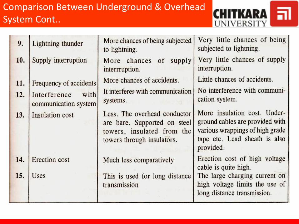
Comparison Between Underground & Overhead System Cont..