underground battery vault - alpha technologies...battery contact, remove all metallic objects, (such...
TRANSCRIPT

Alpha Technologies
Site Preparation and Installation Effective: August 2015
Underground Battery Vault

PowerAlpha Technologies ®

031-040-B0-003 Rev. C1 3
Underground Battery VaultSite Preparation and Installation
031-040-B0-003 Rev. C1Effective Date: August 2015
Copyright © 2015Alpha Technologies, Inc.
Contacting Alpha Technologies: www.alpha.comor
For general product information and customer service (7 AM to 5 PM, Pacific Time), call
1-800-863-3930
For complete technical support, call
1-800-863-33647 AM to 5 PM, Pacific Time and24/7 emergency support
member of The GroupTM
Photographs contained in this manual are for illustrative purposes only. These photographs may not match your installation.
NOTE:
Operator is cautioned to review the drawings and illustrations contained in this manual before proceeding. If there are questions regarding the safe operation of this powering system, please contact Alpha Technologies or your nearest Alpha representative.
NOTE:
Alpha shall not be held liable for any damage or injury involving its enclosures, power supplies, generators, batteries, or other hardware if used or operated in any manner or subject to any condition not consistent with its intended purpose, or is installed or operated in an unapproved manner, or improperly maintained.
NOTE:

031-040-B0-003 Rev. C14
Contents
Safety Notes .......................................................................................................................... 5
Battery Safety Notes.............................................................................................................. 6
Mechanical Safety ................................................................................................................. 6
1. INTRODUCTION ............................................................................................................... 81.1 Underground Battery Vault ....................................................................................................... 8
2. INSTALLATION ................................................................................................................. 92.1 Site Prep and Installation .......................................................................................................... 92.2 Battery Placement .................................................................................................................. 102.3 Battery Connection ................................................................................................................. 122.4 Battery Covers ........................................................................................................................ 18
2.4.1 Installing the Battery covers ............................................................................................. 192.5 Temperature Sensor ............................................................................................................... 21
Figures and TablesFig. 1-1 Underground Battery Vault ................................................................................................. 8Fig. 2-1 Typical site for UBV ............................................................................................................ 9Fig. 2-2 Single 36Vdc Battery String ............................................................................................. 10Fig. 2-3 Dual 36Vdc Battery String ................................................................................................ 10Fig. 2-4 Single 48Vdc Battery String ..............................................................................................11Fig. 2-5 Dual 48Vdc Battery String .................................................................................................11Fig. 2-6 Terminal Connection with Battery Sense Wiring .............................................................. 12Fig. 2-7 AG-CMT-3SC Wiring for Single 36V Battery String ......................................................... 14Fig. 2-8 AG-CMT-3SC Wiring for Dual 36V Battery String ............................................................ 15Fig. 2-9 AG-CMT-4SC Wiring for Single 48V Battery String ......................................................... 16Fig 2-10 AG-CMT-4SC Wiring for Dual 48V Battery String ............................................................ 17Fig. 2-11 165 GXL Battery Cover .................................................................................................... 18Fig. 2-12 180 GXL Battery Cover .................................................................................................... 18Fig. 2-13 165 AGM Battery with Cover in place .............................................................................. 20Fig. 2-14 180 GXL Battery with cover in place ................................................................................ 20Fig. 2-15 Location of Temperature Probe on Battery ...................................................................... 21Fig. 2-16 Temp Probe Connector .................................................................................................... 21
Table 1 Available Options ............................................................................................................... 8Table 2 Part Numbers, Charge Management Technology-related items ...................................... 13

031-040-B0-003 Rev. C1 5
Chemical HazardsTo avoid injury:
• Servicing and connection of batteries shall be performed by, or under the direct supervision of, personnel knowledgeable of batteries and the required safety precautions.
• Always wear eye protection, rubber gloves, and a protective vest when working near batteries. To avoid battery contact, remove all metallic objects, (such as rings or watches), from your person.
• Batteries produce explosive gases. Keep all open flames and sparks away from batteries.• Use tools with insulated handles. Do not rest any tools on top of batteries.• Batteries contain or emit chemicals known to the State of California to cause cancer and birth defects
or other reproductive harm. Battery post terminals and related accessories contain lead and lead compounds. Wash hands after handling (California Proposition 65).
• If any battery emission contacts the skin, wash immediately and thoroughly with water. Follow your company’s approved chemical exposure procedures.
• Neutralize any spilled battery emission with the special solution contained in an approved spill kit or with a solution of one pound bicarbonate of soda to one gallon of water. Report a chemical spill using your company’s spill reporting structure and seek medical attention if necessary.
• Always replace batteries with those of an identical type and rating. Never install old or untested batteries.• Prior to handling the batteries, touch a grounded metal object to dissipate any static charge that may have
developed on your body.• Use special caution when connecting or adjusting battery cabling. An improperly or unconnected battery
cable can make contact with an unintended surface that can result in arcing, fire, or a possible explosion.• A battery showing signs of cracking, leaking, or swelling should be replaced immediately by authorized
personnel using a battery of identical type and rating.
WARNING!
Safety NotesReview the drawings and illustrations contained in this manual before proceeding. If there are any questions regarding the safe installation or operation of the system, contact Alpha Technologies or the nearest Alpha representative. Save this document for future reference.To reduce the risk of injury or death, and to ensure the continued safe operation of this product, the following symbols have been placed throughout this manual. Where these symbols appear, use extra care and attention.
Any gelled or liquid emissions from a valve-regulated lead-acid (VRLA) battery contains dilute sulfuric acid, which is harmful to the skin and eyes. Emissions are electrolytic and are electrically conductive and corrosive.
031-040-B0-003 Rev. C16
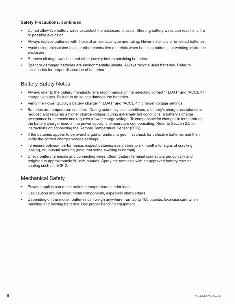
Mechanical Safety• Power supplies can reach extreme temperatures under load. • Use caution around sheet metal components, especially sharp edges.• Depending on the model, batteries can weigh anywhere from 25 to 100 pounds. Exercise care when
handling and moving batteries. Use proper handling equipment.
Safety Precautions, continued
• Do not allow live battery wires to contact the enclosure chassis. Shorting battery wires can result in a fire or possible explosion.• Always replace batteries with those of an identical type and rating. Never install old or untested batteries.• Avoid using uninsulated tools or other conductive materials when handling batteries or working inside the enclosure.• Remove all rings, watches and other jewelry before servicing batteries.• Spent or damaged batteries are environmentally unsafe. Always recycle used batteries. Refer to local codes for proper disposition of batteries
Battery Safety Notes• Always refer to the battery manufacturer’s recommendation for selecting correct “FLOAT” and “ACCEPT” charge voltages. Failure to do so can damage the batteries.• Verify the Power Supply’s battery charger “FLOAT” and “ACCEPT” charger voltage settings.• Batteries are temperature sensitive. During extremely cold conditions, a battery’s charge acceptance is reduced and requires a higher charge voltage; during extremely hot conditions, a battery’s charge acceptance is increased and requires a lower charge voltage. To compensate for changes in temperature, the battery charger used in the power supply is temperature compensating. Refer to Section 2.5 for instructions on connecting the Remote Temperature Sensor (RTS).• If the batteries appear to be overcharged or undercharged, first check for defective batteries and then verify the correct charger voltage settings.• To ensure optimum performance, inspect batteries every three to six months for signs of cracking, leaking, or unusual swelling (note that some swelling is normal).• Check battery terminals and connecting wires. Clean battery terminal connectors periodically and retighten to approximately 50 inch-pounds. Spray the terminals with an approved battery terminal coating such as NCP-2.

031-040-B0-003 Rev. C1 7
IMPORTANT INSTALLATION NOTES
THE SYSTEM SHOULD BE INSTALLED ONLY BY QUALIFIED SERVICE PERSONNEL.
ALWAYS CONSULT LOCAL CODES FOR CONCRETE PAD REQUIREMENTS.
CONSULT LOCAL UTILITY CODES FOR ADDITIONAL CABINET GROUNDING AND UTILITY REQUIREMENTS.
CONSULT THE LOCAL GAS COMPANY FOR CORRECT METER TYPE AND RISER LOCATION.
THE ENCLOSURE SHOULD BE INSTALLED ABOVE FLOOD ZONES WHENEVER POSSIBLE.
THE PAD MUST BE AT LEAST 6” THICK AND CAPABLE OF HOLDING 4,000 LBS (MINIMUM). REBAR SHOULD BE PLACED IN A CROSSHATCH PATTERN FOR PAD REINFORCEMENT.
IF THE PAD IS TO BE LOCATED IN AN AREA WITH A DEEP FROST LINE OR UNSTABLE SOIL, CONCRETE PYLON FOOTINGS (4” DIA. X 4’ DEEP, OR 1’ DEEPER THAN THE REGIONAL FROST LINE) SHOULD BE PLACED BELOW THE CONCRETE PAD, IN FRONT OF AND BELOW THE (6) MOUNTING FEATURES.
THE HEIGHT OF THE PAD MUST BE AT LEAST 4” ABOVE GRADE TO REDUCE THE BUILDUP OF DEBRIS AROUND THE BASE OF THE CABINET.
ADEQUATE SPACE SHOULD BE ALLOWED FOR CABLE TV INPUT / OUTPUT CONDUIT; PLANT GROUNDING ELECTRODE CONDUCTOR(S); RF CABLE ENTRANCE VIA (1) 4”, (2) 3” OR (3) 2 1/2” RIGID CONDUIT SWEEP(S) WITH 2’ BEND RADIUS (MINIMUM); AND FIBER OPTIC CABLE ENTRANCE (REFER TO FIBER MANUFACTURER’S SPECIFICATION FOR MINIMUM BEND RADIUS REQUIREMENTS).
PRIOR TO POURING CONCRETE, ANY WIRE RUNNING THROUGH THE PAD MUST HAVE A THERMAL EXPANSION JACKET (I.E., PVC) TO PREVENT CRACKING OF THE CONCRETE DURING LIGHTNING STRIKES.
ALPHA TECHNOLOGIES IS NOT RESPONSIBLE FOR BROKEN WELDS OR OTHER DAMAGE TO THE CABINET CAUSED BY IMPROPER INSTALLATION.
CONCRETE FILLED, 6” DIAMETER STEEL POSTS (OR EQUIVALENT) SHOULD BE PLACED AT THE CORNERS OF THE PAD TO REDUCE EXPOSURE TO ACCIDENTAL TRAFFIC DAMAGE. POSTS MUST ALSO BE PLACED IN FRONT OF THE GAS UTILITY RISER TO PROTECT THE GAS REGULATOR FROM IMPACT AND / OR DAMAGE FROM LAWN EQUIPMENT.
ALL DIMENSIONS ARE GIVEN IN INCHES.
FOR FURTHER INFORMATION REGARDING THIS INSTALLATION, CONTACT APLHA TECHNOLOGIES OR YOUR NEAREST ALPHA REPRESENTATIVE.

031-040-B0-003 Rev. C18
Alpha’s UBV Series Underground Battery Vaults and BVE enclosures meet municipal and state regulations involving line of sight restrictions. These utility approved vaults are manufactured from high density polyethylene (HDPE) and can house up to eight batteries. Several options are available including combinations with ground and pole mount power supply enclosures.
Hex-head bolts (standard)Penta-head hardware optional)
Cover
Battery compartment
Box, High density polyethelyne
1” thick grate
2.5” PVC Conduit
1. INTRODUCTION
1.1 Underground Battery Vault
Fig. 1-1 Underground Battery Vault (UBV)
Alpha Underground Battery Vault (UBV)
Specifications
HDPE Vault (accommodates up to 8 batteries)
(in): 43.5L x 31.75W x 18H (mm): 105L x 806W x 457H
HDPE Lid
(in): 35.6L x 24.1W(mm): 904L x 612W
Available Options
Part Number Model Description870-180-26 BCK-UBV3 Fused Battery Cable Kit - 3 batteries
874-194-21 BCK-UBV4 Fused Battery Cable Kit - 4 batteries
874-194-22 BCK-UBV6 Fused Battery Cable Kit - 6 batteries
874-194-23 BCK-UBV8 Fused Battery Cable Kit - 8 batteries
875-730-20 Replacement Inline Fuse, 100A
874-195-22 BCK-Extension, 25’ For XM Series 2 Power Supply
874-165-26 BCK-Extension, 25’ Shielded version for XM Series 2 Power Supply*
600-646-C2 6 Battery Tray
630-335-10 UBV-SH Penta Head Hardware
964-028-10 Lifting Hook, Universal, 36"
964-029-10 7/8" Penta Head Socket
744-524-20 UBV-BC-180 Battery Cover for 180 series batteries
745-778-20 UBV-BC-165 Battery Cover for 160 series batteries
740-162-20 RTS-4 Remote Temperature Sensor, 4’ length (supplied with XM2)
744-423-20 RTS-25 Remote Temperature Sensor, 25’ length
*Shielded cables provide EMI Supression required for above-ground XM2 applications where the BCK is routed through an exposed plastic conduit.
Table 1 Available options
031-040-B0-003 Rev. C1 9
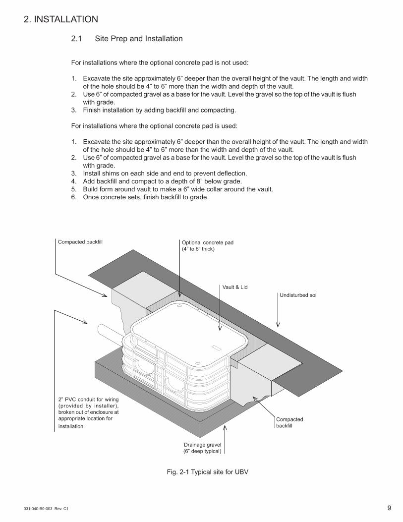
Vault & Lid
Optional concrete pad(4” to 6” thick)
Compacted backfill
Compactedbackfill
Drainage gravel(6” deep typical)
For installations where the optional concrete pad is not used:
1. Excavate the site approximately 6” deeper than the overall height of the vault. The length and width of the hole should be 4” to 6” more than the width and depth of the vault.
2. Use 6” of compacted gravel as a base for the vault. Level the gravel so the top of the vault is flush with grade.
3. Finish installation by adding backfill and compacting.
For installations where the optional concrete pad is used:
1. Excavate the site approximately 6” deeper than the overall height of the vault. The length and width of the hole should be 4” to 6” more than the width and depth of the vault.
2. Use 6” of compacted gravel as a base for the vault. Level the gravel so the top of the vault is flush with grade.
3. Install shims on each side and end to prevent deflection.4. Add backfill and compact to a depth of 8” below grade.5. Build form around vault to make a 6” wide collar around the vault.6. Once concrete sets, finish backfill to grade.
Undisturbed soil
2” PVC conduit for wiring (provided by installer), broken out of enclosure at appropriate location for installation.
2. INSTALLATION
2.1 Site Prep and Installation
Fig. 2-1 Typical site for UBV
031-040-B0-003 Rev. C110
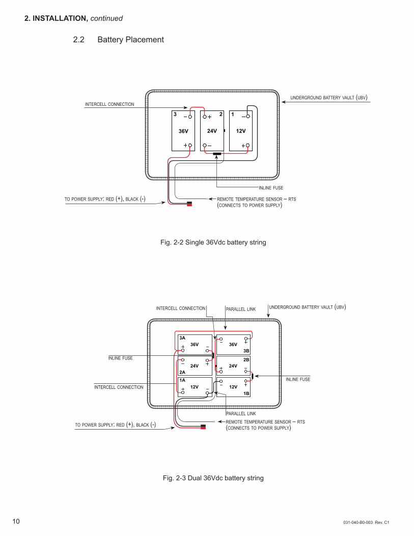
Fig. 2-2 Single 36Vdc battery string
Fig. 2-3 Dual 36Vdc battery string
2. INSTALLATION, continued
underground battery vault (ubv)intercell connection
to power supply: red (+), black (-)
intercell connection underground battery vault (ubv)
inline fuse
inline fuse
to power supply: red (+), black (-)
parallel link
3 12
36V 24V 12V
inline fuse
intercell connection
parallel link
remote temperature sensor – rts(connects to power supply)
remote temperature sensor – rts(connects to power supply)
36V
24V
12V
3A
1A2A
12V
24V
36V
1B
3B
2B
2.2 Battery Placement
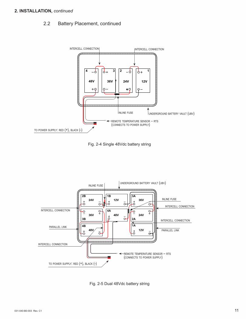
underground battery vault (ubv)
to power supply: red (+), black (-)
intercell connection intercell connection
remote temperature sensor – rts(connects to power supply)
inline fuse
to power supply: red (+), black (-)
intercell connection
underground battery vault (ubv)inline fuse
intercell connection
intercell connection
intercell connection
inline fuse
parallel linkparallel link
remote temperature sensor – rts(connects to power supply)
4 23
48V 36V 24V
1
12V
031-040-B0-003 Rev. C1 11
48V4A
36V3B
24V2A
12V1B
24V2B
36V3A
12V1A
48V4B
2.2 Battery Placement, continued
Fig. 2-4 Single 48Vdc battery string
Fig. 2-5 Dual 48Vdc battery string
2. INSTALLATION, continued

031-040-B0-003 Rev. C112
Depending on the size of the vault, strings of 3, 4, 6, or 8 batteries may be installed, along with an optional AlphaGuard Battery Monitoring system. After securing the UBV, and installing the batteries, make the wire connections to the batteries as shown.
Installation and Connection Procedure:
1. Label the batteries. 2. Install the batteries into the underground battery vault. 3. Connect batteries in as shown in the accompanying diagrams, and tighten harware to battery manufacturer's specifications. 4. Tape Remote temperature sensor (RTS) to side of battery. 5. If an optional AlphaGuard Battery Sense Monitor is incorporated into the battery system, connect the battery sense wires as shown. 6. Apply corrosion inhibitor to terminal assembly after tightening.
Route the battery cable connectors from the enclosure, ring lugs first to the UBV.
NOTE:
Verify the battery voltage and polarity are correct before proceeding.
NOTE:
2. INSTALLATION, continued
2.3 Battery Connection
3/4" x1/4-20 bolt
split washer
battery sense wire (from optional alphaguard)
battery cable
flat washer
Fig. 2-6 Terminal Connection with Battery Sense Wiring
031-040-B0-003 Rev. C1 13
2. INSTALLATION, continued
2.3 Battery Connection, continued
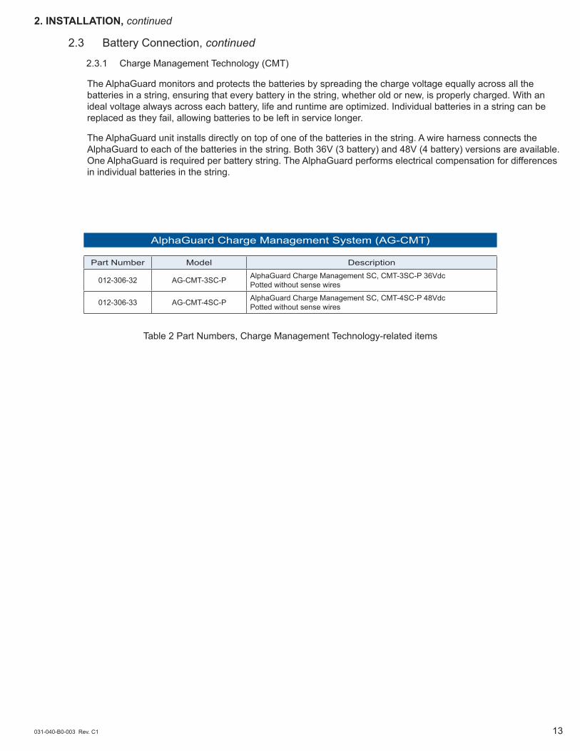
2.3.1 Charge Management Technology (CMT)
The AlphaGuard monitors and protects the batteries by spreading the charge voltage equally across all the batteries in a string, ensuring that every battery in the string, whether old or new, is properly charged. With an ideal voltage always across each battery, life and runtime are optimized. Individual batteries in a string can be replaced as they fail, allowing batteries to be left in service longer.
The AlphaGuard unit installs directly on top of one of the batteries in the string. A wire harness connects the AlphaGuard to each of the batteries in the string. Both 36V (3 battery) and 48V (4 battery) versions are available. One AlphaGuard is required per battery string. The AlphaGuard performs electrical compensation for differences in individual batteries in the string.
AlphaGuard Charge Management System (AG-CMT)
Part Number Model Description
012-306-32 AG-CMT-3SC-P AlphaGuard Charge Management SC, CMT-3SC-P 36Vdc Potted without sense wires
012-306-33 AG-CMT-4SC-P AlphaGuard Charge Management SC, CMT-4SC-P 48Vdc Potted without sense wires
Table 2 Part Numbers, Charge Management Technology-related items
+
- +
- +
-
12V24V36V
3 12
031-040-B0-003 Rev. C114
2. INSTALLATION, continued
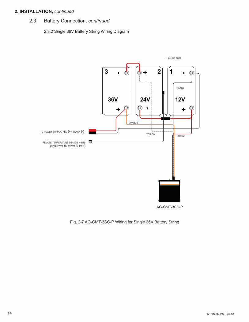
2.3 Battery Connection, continued
2.3.2 Single 36V Battery String Wiring Diagram
orange
yellow
AG-CMT-3SC-P
Fig. 2-7 AG-CMT-3SC-P Wiring for Single 36V Battery String
remote temperature sensor – rts (connects to power supply)
to power supply: red (+), black (-)brown
black
inline fuse

Brown
+ -
+-
+
-
12V
24V
36V
+-
+ -
+-
12V
24V
36V
1A
2A
3A
3B
2B
1B
black
031-040-B0-003 Rev. C1 15
or
an
ge
yellow
inline fuse
inline fuse
yellow
or
an
ge
AG-CMT-3SC-P
AG-CMT-3SC-P
2. INSTALLATION, continued
2.3 Battery Connection, continued
2.3.3 Dual 36V Battery String Wiring Diagram
Fig. 2-8 AG-CMT-3SC-P Wiring for Dual 36V Battery String
remote temperature sensor – rts (connects to power supply)
to power supply: red (+), black (-)
black
AB
4 23
48V 36V 24V
1
12V
AG-CMT-4SC-P
031-040-B0-003 Rev. C116
2. INSTALLATION, continued
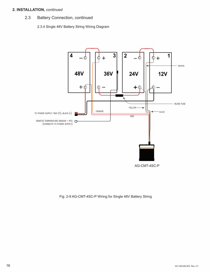
2.3 Battery Connection, continued
2.3.4 Single 48V Battery String Wiring Diagram
Fig. 2-9 AG-CMT-4SC-P Wiring for Single 48V Battery String
remote temperature sensor – rts (connects to power supply)
to power supply: red (+), black (-)
brown
orangeyellow
red
inline fuse
black
48V4A
36V3B
24V2A
12V1B
24V2B
36V3A
12V1A
48V4B
brown
orange
yellow
red
AG-CMT-4SC-P
AG-CMT-4SC-P
orange
inline fuse
031-040-B0-003 Rev. C1 17
2. INSTALLATION, continued
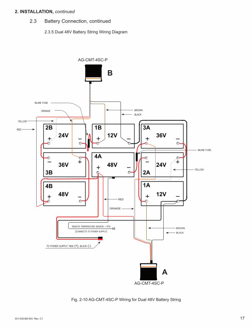
2.3 Battery Connection, continued
2.3.5 Dual 48V Battery String Wiring Diagram
Fig. 2-10 AG-CMT-4SC-P Wiring for Dual 48V Battery String
to power supply: red (+), black (-)
inline fuse
remote temperature sensor – rts (connects to power supply)
yellow
black
red
brownblack
A
B
031-040-B0-003 Rev. C118
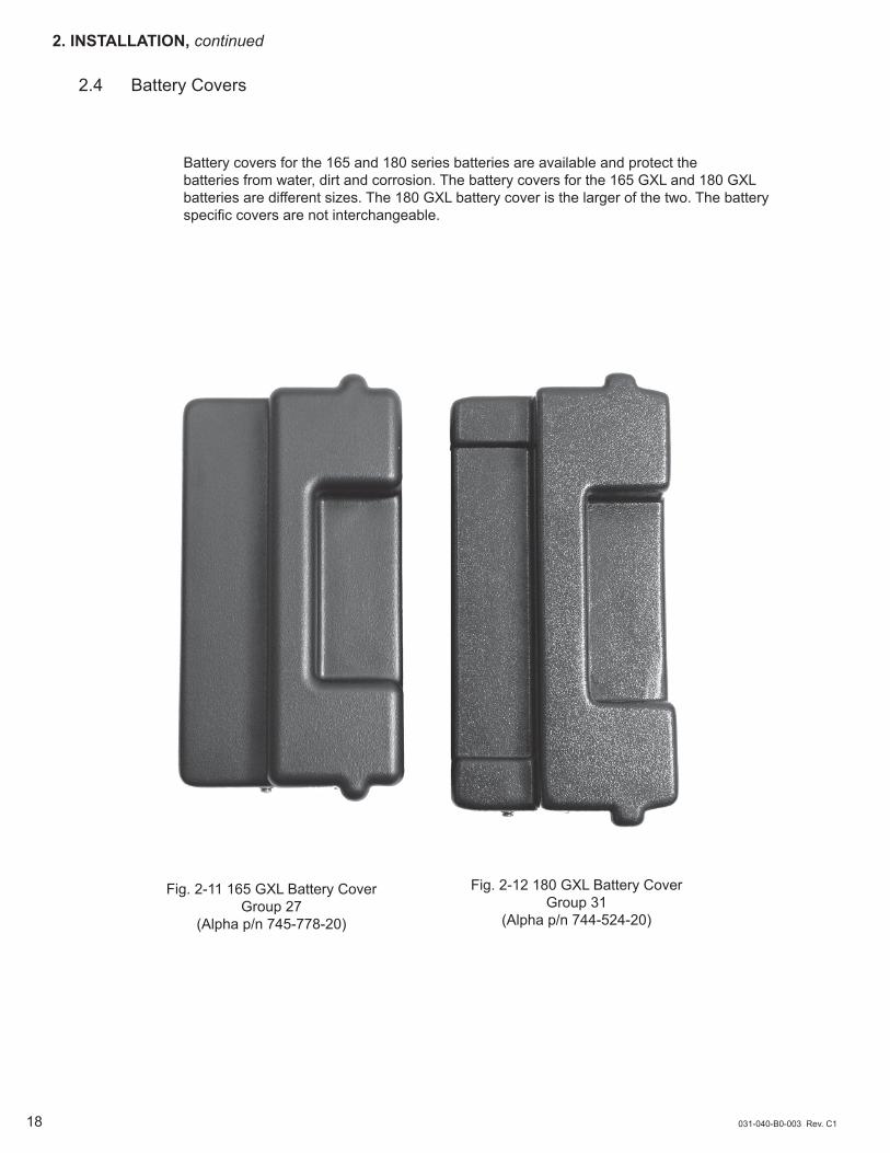
Battery covers for the 165 and 180 series batteries are available and protect the batteries from water, dirt and corrosion. The battery covers for the 165 GXL and 180 GXL batteries are different sizes. The 180 GXL battery cover is the larger of the two. The battery specific covers are not interchangeable.
2. INSTALLATION, continued
2.4 Battery Covers
Fig. 2-11 165 GXL Battery CoverGroup 27
(Alpha p/n 745-778-20)
Fig. 2-12 180 GXL Battery CoverGroup 31
(Alpha p/n 744-524-20)
031-040-B0-003 Rev. C1 19
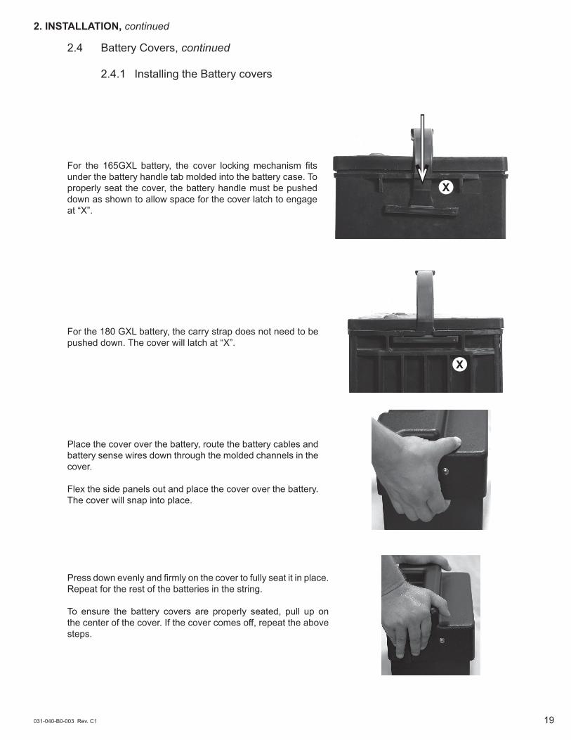
For the 165GXL battery, the cover locking mechanism fits under the battery handle tab molded into the battery case. To properly seat the cover, the battery handle must be pushed down as shown to allow space for the cover latch to engage at “X”.
X
X
For the 180 GXL battery, the carry strap does not need to be pushed down. The cover will latch at “X”.
Place the cover over the battery, route the battery cables and battery sense wires down through the molded channels in the cover.
Flex the side panels out and place the cover over the battery. The cover will snap into place.
Press down evenly and firmly on the cover to fully seat it in place. Repeat for the rest of the batteries in the string.
To ensure the battery covers are properly seated, pull up on the center of the cover. If the cover comes off, repeat the above steps.
2. INSTALLATION, continued
2.4 Battery Covers, continued
2.4.1 Installing the Battery covers
031-040-B0-003 Rev. C120
2. INSTALLATION, continued
2.4 Battery Covers, continued
2.4.1 Installing the Battery Covers, continued
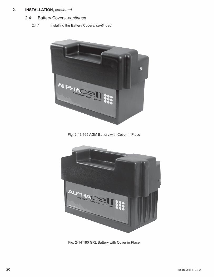
Fig. 2-13 165 AGM Battery with Cover in Place
Fig. 2-14 180 GXL Battery with Cover in Place

031-040-B0-003 Rev. C1 21
Temp Probe Connector: The Remote Temperature Sensor (RTS) plugs directly into the temperature probe (RJ-11C type) connector. The sensor end of the RTS is routed to the battery compartment and taped directly to the side of the center battery (See Fig. 2-12). The RTS provides battery temperature measurements used to adjust the battery charge voltage. Attach the probe to the side of the battery so that it is protected by the cover.
2. INSTALLATION, continued
2.5 Temperature Sensor
Fig. 2-15 Location of Temperature Probe on Battery
Fig. 2-16 Temp Probe Connector

this page intentionally blank


Alpha Technologies3767 Alpha WayBellingham, WA 98226USATel: +1 360 647 2360Fax: +1 360 671 4936Web: www.alpha.com
Alpha Technologies Ltd.4084 McConnell CourtBurnaby, BC, V5A 3N7CANADATel: +1 604 430 1476Fax: +1 604 430 8908
Alpha TechnologiesEurope Ltd.Twyford House ThorleyBishop's StortfordHertfordshire CM22 7PAUNITED KINGDOMTel: +44 0 1279 501110Fax: +44 1 279 659870
Alpha Technologies GmbHHansastrasse 8D 91126 SchwabachGERMANYTel: +49 9122 79889 0Fax: +49 9122 79889 21
Alphatec, Ltd339 St. Andrews StreetSuite 101 Andrea Chambers3307 LimassolCYPRUSTel: +357 25 375675Fax: +357 25 359595
AlphaTEK oooKhokhlovskiy Pereulok 16Stroenie 1 Office 403109028 MoscowRUSSIATel: +7 495 916 1854Fax: +7 495 916 1349
Alphatec Baltic S. Konarskio Street G.49-201Vilnius LT-03123LITHUANIATel: +370 5 210 5291Fax: +370 5 210 5292
Alpha Technologies34, Grande RueBétheny, F-51450FrancePhone: +33 32 64990 54Fax: +33 67 54289 44
Due to continuing product improvements, Alpha reserves the right to change specifications without notice. Copyright © 2015 Alpha Technologies, Inc. All rights reserved. Alpha is a registered trademark of Alpha Technologies. 031-040-B0-003 Rev. C1
PowerAlpha Technologies ®