underfloor wheel lathe type u 200 0-150 - servus · the underfloor wheel lathe ... connection data...
TRANSCRIPT

Type U 2000-150
Underfloor Wheel Lathe
... technology in motion
CNC-controlled machine with automatic measuring system
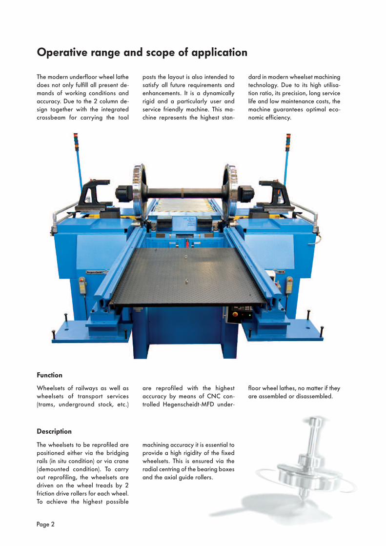
The modern underfloor wheel lathedoes not only fulfill all present de-mands of working conditions andaccuracy. Due to the 2 column de-sign together with the integratedcrossbeam for carrying the tool
dard in modern wheelset machiningtechnology. Due to its high utilisa-tion ratio, its precision, long servicelife and low maintenance costs, themachine guarantees optimal eco-nomic efficiency.
posts the layout is also intended tosatisfy all future requirements andenhancements. It is a dynamicallyrigid and a particularly user andservice friendly machine. This ma-chine represents the highest stan-
Wheelsets of railways as well aswheelsets of transport services(trams, underground stock, etc.)
floor wheel lathes, no matter if theyare assembled or disassembled.
are reprofiled with the highest accu racy by means of CNC con-trolled Hegenscheidt-MFD under-
The wheelsets to be reprofiled arepositioned either via the bridgingrails (in situ condition) or via crane(demounted condition). To carry out reprofiling, the wheelsets aredriven on the wheel treads by 2 friction drive rollers for each wheel.To achieve the highest possible
machining accuracy it is essential toprovide a high rigidity of the fixedwheelsets. This is ensured via the radial centring of the bearing boxesand the axial guide rollers.
Page 2
Operative range and scope of application
Function
Description

The Underfloor Wheel Latheis suitable for:
• Reprofiling of wheelsets
• Partial reprofiling of wheelsets
• Machining of the inner and outer wheel face
• Reprofiling of individual wheels
• Machining of axle and/or wheel mounted brake discs (optional)
The machine is operated via a cen-tral control panel so that the opera-tor has continuous access to all machine functions while being in the optimal working position.
At the same time during machining,the operator is protected againstswarf.
The automated machining system is designed to provide the machineuser with easily understandable ma-chining menues.
The prepared machine cycles givesa machine that is operator friendlyand easy to use.
Page 3

• 2 machine columns• Cross beam• 2 tool posts with integrated automatic measuring system
• 2 friction roller drives (roller carrier with drive unit)
• Electrical equipment• Hydraulics• Machine housing• Integrated swarf conveyor• CNC control Sinumerik 840 DE, make Siemens, operator guidance in proposed language
• Wheelset position indication
• Outer bearing box centring with adapters
• Inner bearing box centring with adapters
• Rail system
• Swarf shredding devices
• Chip disposal (adaptation to the local conditions)
• Jacking for coupled wheel set equipment
• Necessary extensions according to machining task
Page 4
The base machine is a standard unitwhich is CNC controlled and de-signed to lift, measure and machinea wheelset.
A tandem version, for simultaneousmachining of bogies is also avail-able.
Machine Design
Standard components The basic machine consists of the following as standard:
Customer or vehicle specific components:
• Chip breakage control system
• Interruption on tool breakage (push button operated) with automatic repositioning at point of interruption
• Data storage
• Additional wheel profiles programmable
• Customised enhancements upon request
• Brake disc machining equipment
• Brake disc machining tools
• Additional centre adapters
• Antislip control unit
Other options available to extend the machine range and to increase the degree of automation:

Page 5
Advantages
The advantages of this machine are:
• Machine-integrated housing with optimised swarf evacuation ensures improved health and safety conditions for the operator.
• Integrated swarf guiding plates and large openings to the integrated swarf conveyor and / or chip crusher facilitate easy swarf evacuation.
• Simple approach to majority of disc brake types due to the new design of the toolposts.
• Permanent accuracy of the guiding elements for the toolposts.
• Oil lubrication of the toolposts is replaced by grease lubrication due to environmental aspects and simplified maintenance.
• All accuracy-relevant components (i.e. linear roller elements for guiding the toolposts) are designed for less maintenance and wear.
• The machine arrives on site completely preassembled and can be put into operation within a very short time.
• Compact machine design facilitates smaller pit dimensions.
• Simple foundation design eliminating cable ducts, since the main switchgear cabinet is an integrated part of the machine.
• Modular design enables further enhancements and add-ons (i.e. data transfer, additional holddown claws, etc.)
Page 6
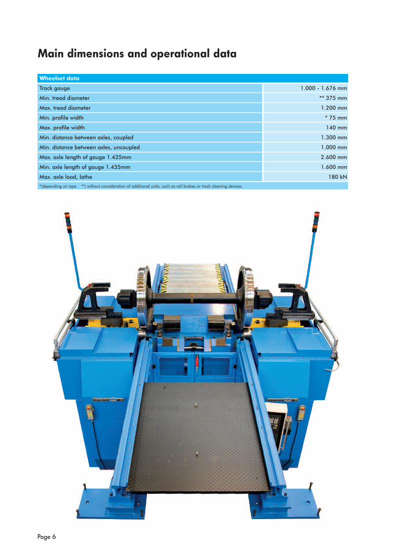
Main dimensions and operational data
Wheelset data
Track gauge 1.000 - 1.676 mm
Min. tread diameter ** 375 mm
Max. tread diameter 1.200 mm
Min. profile width * 75 mm
Max. profile width 140 mm
Min. distance between axles, coupled 1.300 mm
Min. distance between axles, uncoupled 1.000 mm
Max. axle length of gauge 1.435mm 2.600 mm
Min. axle length of gauge 1.435mm 1.600 mm
Max. axle load, lathe 180 kN
*)depending on type **) without consideration of additional units, such as rail brakes or track cleaning devices.

Connection data
Executed according to VDE, EN and IEC regulations (other regulations upon request)
Operating voltage 400 V *
Mains frequency 50 Hz *
Mains type TN
Connected power 80 kVA
Machine weight approx. 160 kN
Space requirements (L x W) approx. 5,7 m x 6 m **
Foundation pit depth approx. 2,3 m
* alternative values possible ** at gauge 1,435 mm (for other gauges on request)
Machine dataDrive rating 4 x 9 kW
Cutting force (if axle load is sufficient) 26 kN
Maximum cross section of cut (each tool post) 6 mm2 *
Speed range of main drives, infinitely variable
- at constant torque
- at constant rating
0 – 1.500
1.500 – 6.500
min-1
min-1
Cutting speed range
- at constant torque (drive rollers)
- at constant rating (drive rollers)
0 – 70
70 – 305
m/min
m/min
Cutting speed
- at machining profiles
- at machining disc brakes constant
20 – 120
120
m/min
m/min
Tool post fast speed transversal x-axis 3 m/min
Tool post fast speed longitudinal z-axis 4,7 m/min
Feed range, infinetely variable 0 - 2,5 mm/rev
Axle distance between drive rollers 370 mm
Diameter of drive rollers 190 mm
Maximum noise level of the machine (without machining) dB (A)
Measuring system of the machine metric
* depending on axle load and additional load
Machining accuracy 1)
1) Form an geometrical tolerances acc. DIN / ISO 1101
Machining profile
Radial run out of tread mm 3) 5)
Lateral wobble mm 4) 5)
Deviation from nominal profile geometry mm
Maximum diameter difference of two wheels on one axle mm 2)
Maximum diameter difference of four wheels on one bogie mm 2)
Surface finish profile R µm
Surface finish inner and outer wheel faces R µm
2) requiring identical stock material on both wheels, sharp cutting tools, precise and stiff clamping of the axle bearing box. Depth of cut 4 mm (2 cuts)3) requires measuring cut, roughing cut or round wheels as well as perfect cutting tools, regular cutting conditions and correct radial centring of wheels4) requires lateral wobble < 0.5 mm5) when turning resilient wheelsets an increase of the given value up to 0.3 mm has to be considered
Machining brake discs
Lateral wobble mm
Planeness mm/100 mm
Surface finish R µm
Page 7

Hegenscheidt-MFD GmbH & Co KG Postfach 1652 • D-41806 ErkelenzHegenscheidt Platz • D-41812 Erkelenz Fon +49(0)24 31 86-0 • FAX +49(0)24 31 86-466 Email: [email protected] Internet: www.hegenscheidt-mfd.de
A Member of ...
... technology in motion
GP
078
EN H
M-P
C 0
9.04
- S
ubje
ct to
tech
nica
l cha
nges