unconventional methods of measuring residual stressarticle is described methodical process of...
TRANSCRIPT

BULETIN ŞTIINŢIFIC, Seria C, Fascicola: Mecanică, Tribologie, Tehnologia Construcţiilor de Maşini SCIENTIFIC BULLETIN, Serie C, Fascicle: Mechanics, Tribology, Machine Manufacturing Technology, ISSN 1224-3264, Volume 2016 No.XXX
71
Unconventional Methods of Measuring Residual Stress
Dusan Mital1*, František Botko1 *, Michal Hatala1, Andrej Bernat1, Katarina Brezikova1
Abstract: Article is focused on using eddy current to measure of internal residual stress after milling. In presented article is described methodical process of identification residual stress in internal layers of the surface after machining of steel C45. Eddy current provides fast identification of residual stress directly in engineering areas without necessity to transfer samples in specialized laboratories. Presented article also describe procedure of evaluating measured values of deviation and its transformation to values of residual stress by conversion coefficients. Keywords: EC testing, measurement, steel, residual stress 1 INTRODUCTION
Monitoring the quality of the surface is a detailed
description of production technology and the impact of the component as a key aspect in assessing the effectiveness thus productivity. The actual quality of productivity is directly proportional to the new technologies, materials that affect the quality of the machined surface because in improving the efficiency of production it leads to greater energy transfer directly onto the workpiece. In terms of production quality are defined three basic terms under which it is possible to assess the quality of the machined surface [1], [6]:
• precision shape dimensions, • roughness and microstructure, • characteristics of the surface and the surface
layer. Accuracy of shape dimension is derived from a
number of factors such as the rigidity of the machine itself, the interaction between stiffness and machine-tool, the temperature at the incision site (i.e. dilatation effects of heat). Surface quality in terms of roughness and microstructure depends precisely on the machining process. The most important parameters that affect the quality of the machined surface (except the geometric dimensions of the cutting tool) are: cutting speed, depth of cut, feed rate, tool quality, etc. [1], [2], [5].
Characteristics of surface and subsurface layers are characterized by changes in the structure, change the modulus of elasticity, which is mainly influenced by residual stresses in the surface and subsurface layers of the workpiece. The statistical studies aimed to describe the defective conditions in engineering were set final evaluations that most defects that occurred on devices were caused precisely the effects of errors in the surface and subsurface layers. In pursuing the fatigue strength is shown that the most important technological operations affect the surface and subsurface layers that are exposed to the maximum force effects tools [1], [3], [6].
The integrity of the surface reflection is thus cutting conditions of machining of functional surfaces of the product, which are taken into consideration of the reaction force of technological methods and operations of the surface finish relative to the operational conditions of the manufactured product [2].
Each technological operation which is performed on the surface of the material causes in the surface and subsurface reconstruction of atoms, molecules and grains of the material. The technology directly affects the
subsurface layer of workpiece (temperature, chemical reactions, cutting forces, etc.). Residual stresses are formed by elastic-plastic deformation in cutting zone (instead of removing material). The main causes of residual stresses are 3 basic factories [4], [5]:
• uneven distribution of plastic deformation in materials,
• uniformity of the heat loads of the material during operation, which is manifested by dilatation and download material,
• uneven changes in the structure caused by the cutting forces formed by heat-machining technology.
Residual stress can be classified into three groups respectively classes:
I. class: the macroscopic stress arising from the treatment of the material itself, in its forming, joining, and etc. (operating in the deep layers of the volume of material),
II. class: tension acting in grains and crystals in small volumes,
III. class: stress acting in the carbon material (dislocations, vacancies, substitutions, etc).
The formation thermal residual stress occurs during cooling of the material, which at decreasing temperature decreases the ductility of the material surface. On cooling, the material in the lower part reduces the volume of grains, which are formed on the surface tensile stresses and below the compressive pressure. On the edges and surfaces appear microscopic cracks and fissures (Fig. 1) [1], [4].
Fig. 1 Thermal residual stress a) cracks on edges b)
fissures on the surface When determining a suitable alternative
measurement of residual stresses is necessary to know the parameters of these methods. When deciding noting the fact whether or damage using destructive methods canceled or semi destructive functional role of the product. Comparison of different methods is shown in following Table 1 [6], [7].

BULETIN ŞTIINŢIFIC, Seria C, Fascicola: Mecanică, Tribologie, Tehnologia Construcţiilor de Maşini SCIENTIFIC BULLETIN, Serie C, Fascicle: Mechanics, Tribology, Machine Manufacturing Technology, ISSN 1224-3264, Volume 2016 No.XXX
72
Table 1 Comparison of residual measurement methods
Method Discern ability Accuracy Drill method 50 µm ± 50 MPa
RTG diffraction 20 µm ± 20 MPa limited
to sin Y or surface
Hard RTG rays 20 µm and to 1 µm in collinear
direction
± 0,05 deformation + 10
% real stress
Neutron diffraction 500 µm
± 0,05 deformation + 10
% real stress
Ultrasound 5 mm 10 % failure of measuring
Magnetic measuring 1 mm 50 MPa
When In the experiment, the article describes a
new methodology for measuring the action of eddy currents. They can be defined as the induced currents arising in the conductive material present in an alternating magnetic field, or moving in a constant magnetic field (magnetic field lines intersect). Swirl currents flow in a plane perpendicular to the direction of magnetic flux f. Their direction can be determined on the basis on Lencz law, where eddy currents flow in closed loops (most are around the perimeter and at least in the middle) [6].
2 EXPERIMENTAL PART Due to the requirements of manufacturing
companies to rapidly and non-destructive testing of residual stress right after machining, started possibility of detection using eddy current (as one of the alternatives, because these methods are used commercially to detect internal defects). Production of special measuring device for measuring subsurface residual stress is unprofitable.
Material intended for machining - structural steel 12 050 (according to EN ISO C45; EN 10083-2-91). This steel is intended for refining (or normalization) and is often used to produce less stressed parts of machinery. C45 chemical composition of steel is given in percentage changes in the following Table 2. Mechanical properties of steel C45 is shown in following table (Tab.3).
Table 2 Chemical composition of steel C45
Chemical element
C Mn Si Cr Ni Cu P S
% ratio
0,51
0,69
0,25
0,15 0 0,1
2 0,02
3 0,01
7
Table 3 Mechanical properties of steel C45 Name Signification and unit Value
Yield stress Rp [MPa] 350 Yield strength Rm [MPa] 630 Ductility A [%] 19 Hardness HB 225 Tensile module E [GPa] 211
Surface components were milled on two crossings
with cooling, because of insufficient diameter of tool (diameter D = 63 mm, 6 teeth). Before the milling was single polished surfaces to eliminate surface imperfections caused by dividing frame saw. The samples were placed separately from each other, because of the elimination of mutual interactions between them. The measuring method using eddy current technique is sorted into groups of non-destructive testing. As indicated in the analysis, the method uses the induced currents in the conductive material and that will input the alternating magnetic field, the AC, the supply current of the coil. The aim of this method is demonstrated influence the occurrence of residual stresses on the change of conductivity, respectively, to change the permeability of the material in the areas of intrusion eddy currents and thus the residual stresses
Fig. 2 Measuring system ZETEC MIZ - 22 EDDY CURRENT INSTRUMENT (1- control functions, 2 -
button ON OFF 3 - clear lubrication, 4 - balance, 5 - freezing the screen 6 - reflective sensor, 7 - differential
sensor, 8 - external connector to connecting peripherals 9 - analog output, 10 - power, 11 - display) Experimental measurements of subsurface
residual stress was on a measuring device of ZETEC (type designation are disappearing 22 EDDY CURRENT INSTRUMENT) (Fig. 2). The device has been designed by means of eddy current testing or detecting material and detecting defects, coating thickness respectively. The thickness of the material was measured, direct conductivity detection and metallurgical changes (such as conductivity, permeability, and change feriticity).
Measuring probe was chosen based on the following criteria. The first criterion was the average probe (as it was set as a requirement for accurate measurement in terms of geometric requirements). The second criterion was to dial the appropriate frequency of
BULETIN ŞTIINŢIFIC, Seria C, Fascicola: Mecanică, Tribologie, Tehnologia Construcţiilor de Maşini SCIENTIFIC BULLETIN, Serie C, Fascicle: Mechanics, Tribology, Machine Manufacturing Technology, ISSN 1224-3264, Volume 2016 No.XXX
73
the probes (for the most significant changes in conductivity and permeability due to internal residual stresses). The most appropriate variant was chosen probe with a frequency of 150 kHz type Ferster nf. 58 (type designation 2.830.01 2011), which means that sensor works absolutely. Diameter of the probe is 12 mm (Fig.3).
Fig. 3 Measuring probe
Before measurement, it was necessary to adjust the measuring device for verification points, because this method is considered to be evaluative, where the impact of residual stresses and their proportional variation of conductivity and permeability are compared with a verification known value of conductivity in this case the subsurface residual stress. In the case of this experiment was elected verification value 250MPa for materials C45, where the value was set to zero to measure and value of this point was balancing in the coordinate system of the position of the X-axis value of 5 in the Y-direction to point 3. In However, the first step was necessary calibrated measuring device (Fig.4). The actual calibration procedure as follows:
• turning the ON / OFF button, • involvement of the probe and load frequency
probe if it has taken place automatically set to 150 kHz, • vacant possession of the probe in the air,
teetering on the desired point [X, Y] → [5, 3], • attach the probe to a friend ferromagnetic
material with a known conductivity, • moving air phase compared to the axis parallel
to the Y axis and also teetering on the point [5, 3] • re-attach the probe to a known material C45
with a known value of residual stress of 250 MPa, • the balance signal to the desired point [5,3] and
the phase shift in the axis parallel to the Y axis, • for experimental testing of 1-15 samples at
selected points of measurement.
Fig. 4 Settings of measuring device ZETEC MIZ – 22
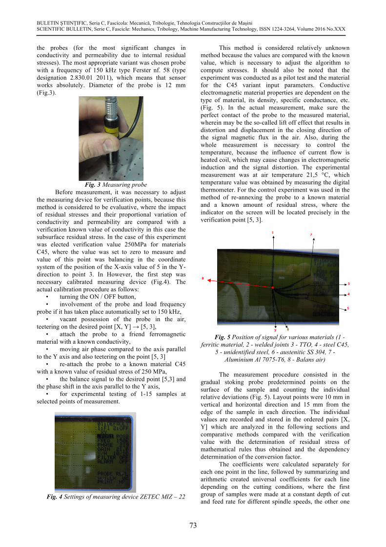
This method is considered relatively unknown method because the values are compared with the known value, which is necessary to adjust the algorithm to compute stresses. It should also be noted that the experiment was conducted as a pilot test and the material for the C45 variant input parameters. Conductive electromagnetic material properties are dependent on the type of material, its density, specific conductance, etc. (Fig. 5). In the actual measurement, make sure the perfect contact of the probe to the measured material, wherein may be the so-called lift off effect that results in distortion and displacement in the closing direction of the signal magnetic flux in the air. Also, during the whole measurement is necessary to control the temperature, because the influence of current flow is heated coil, which may cause changes in electromagnetic induction and the signal distortion. The experimental measurement was at air temperature 21,5 °C, which temperature value was obtained by measuring the digital thermometer. For the control experiment was used in the method of re-annexing the probe to a known material and a known amount of residual stress, where the indicator on the screen will be located precisely in the verification point [5, 3].
Fig. 5 Position of signal for various materials (1 -
ferritic material, 2 - welded joints 3 - TTO, 4 - steel C45, 5 - unidentified steel, 6 - austenitic SS 304, 7 -
Aluminium Al 7075-T6, 8 - Balans air) The measurement procedure consisted in the
gradual stoking probe predetermined points on the surface of the sample and counting the individual relative deviations (Fig. 5). Layout points were 10 mm in vertical and horizontal direction and 15 mm from the edge of the sample in each direction. The individual values are recorded and stored in the ordered pairs [X, Y] which are analyzed in the following sections and comparative methods compared with the verification value with the determination of residual stress of mathematical rules thus obtained and the dependency determination of the conversion factor.
The coefficients were calculated separately for each one point in the line, followed by summarizing and arithmetic created universal coefficients for each line depending on the cutting conditions, where the first group of samples were made at a constant depth of cut and feed rate for different spindle speeds, the other one

BULETIN ŞTIINŢIFIC, Seria C, Fascicola: Mecanică, Tribologie, Tehnologia Construcţiilor de Maşini SCIENTIFIC BULLETIN, Serie C, Fascicle: Mechanics, Tribology, Machine Manufacturing Technology, ISSN 1224-3264, Volume 2016 No.XXX
74
of the values conversion factors for variant values the flow rate at constant spindle speed and depth of cut and the final third group is the constant spindle speed and cutting speed in changing the flow rate parameters. Values with a minus sign indicate that the value of the residual stress is at a level lower than the residual calibration point thus 250MPa. The fair value of the stress can be obtained by a simple calculation and adding the value of residual voltage calibration point at the result.
3. CONCLUSION
Article clearly demonstrates the dependence of
the effect of residual stresses on the impact of variations in the conductivity and permeability. In article is also presented possibility of using this method directly in engineering areas to fast identification residual stress after cooling the components.
Using average coefficients receive information only about the size of subsurface residual stress. From the plot also indicates that the maximum residual stress generated at the point of contact and the exit of tool from material for up milling method. The voltage at the exit point of the instrument is on average 30% lower than at the point of contact with the material mills. The overall assessment of the course of residual stress analysis was employed averages cross distances around the measured surface.
In the analysis of eddy current values obtained it is obvious that the deflection in the Y of the influence of residual stresses more pronounced than the displacement X, therefore, this travel is intended to be the primary, and travel as a secondary X as a verification value, therefore, the amplitude Y then the conversion factors have been established according the distance from the surface of the axis perpendicular to the direction of advance of the tool, which transfers values for displacement in the Y-axis are 25 mm from the surface 32 at a distance of 45 mm value of the transmission coefficient has a value of 50 and at a distance of 75 mm, the coefficient value calculated at the 41. Average calculated coefficient of conversion coefficient is 40,2 with dispersion under 50 MPa. ACKNOWLEDGEMENTS
This paper has been elaborated in the framework of the project of the project VEGA 1/0492/16.
REFERENCES
[1] P. A. Viktor, Surface Integrity – Definition and Importance in Functional Performance, Surface integrity. (2009) 1-36.
[2] P. J. Davim, Surface Integrity in Machining, London, 2009.
[3] G. Totten, Handbook on residual stress, SEM, Bethel, 2005.
[4] V. Trufyakov, P. Mikheev, Y. Kudryavtsev, Fatigue Strength of Welded Structures, Hardwood Academic, London, 1999.
[5] L. Radziszewski, Propagation Parameters of ultrasonic Waves in Polymer Composites, Archives of Acoustic. 4 (2000) 465-478.
[6] M. Hatala, J. Zajac, R. Čep, I. Orlovský, Research of the technological parameters importance for plasma arc thermal cutting, Applied Mechanics and Materials. (2012) 110-116.
[7] P. Beraxa, L. Parilák, M. Ulbrichtová, Increasing Service Life of Tools by CVD Coating, Hutnicke listy. 3 (2010) 37-41.
[8] Šomšáková, Z.; Tarasovi ová, A.; Kasina, M.: Study of materials with natural reinforce-ment and thermo plastic matrix (Wood Plastic Composite), In: Internet Journal of Engi-neering and Technology for Young Scientists. Ro . 1, . 1 (2010), s. 1 6. ISSN 1338 2365.
Authors addresses
1 Faculty of Manufacturing Technologies TUKE with a seat in Prešov, Bayerova 1,08001 Prešov, Slovakia
Contact person
* Dusan Mital, Faculty of Manufacturing Technologies TUKE with a seat in Prešov, Bayerova 1,08001 Prešov, Slovakia Email: [email protected]