unclassified e/lllleeellie intelligence lab a shading … · abstract entered in block 2n, itdlorn...
TRANSCRIPT
-AiB4 848 SHAPE FROM SHADING OCCLUSION AND TEXTURE(U) t/7MASSACHUSETTS INST OF TECH CRMBRIDGE ARTIFICIALINTELLIGENCE LAB A L YUILLE MAY 87 AI-M-885
UNCLASSIFIED N88914-85-K-8124 F/G 23/3E/llllEEElliEEliEElihElhhhEilllEEEEEllliEEEElhhEElhhlhEEu.
1 .0 alowE28a LM
I." I 30 I 8
MICROCOPY RESOLUTION TEST CHARTNATIONAL BUREAU OF STANDARDS-1963-A
14,1 p 9 r 1'* "10 W WJ% ~
%~
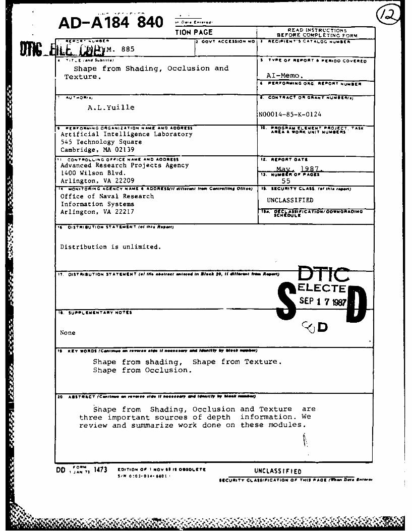
-INPG READ INSTRUCTIONSnONPAG BEFORE COMPLETING FORM
gTIIE00"' NSEQ 885 GOVT ACCESSION NO I RECIPIENT'S CATALOG wNMUER
4 i T, E (and S,6mb * S, TYPE OF REPORT & PERIOD COVERED
Shape from Shading, occlusion andTexture. IAl-Memo.
6 PERFORMING ORG. REPORT NUM@UER
AU T OR(@) S. CONTRACT O0R GRANT NUMUIIERsj
A.L .YuilleNOQO 14-85-K-O 124
9 PERFORMING ORGANIZATION NAME ANO ADDRESS 10. PROGRAM ELEMENT PROJECT TASK
Artificial Intelligence Laboratory AREA G WORK UNIT NUMBERS
545 Technology SquareCambridge, MA 021.391CONTROLLING OFFICE NAME ANO ADDRESS 12. REPORT DATE
Advanced Research Projects Agency 19871400 Wilson Blvd. 13. NUNS OrP PAGES
Arlington, VA 22209 5514 MONITORING AGENCY NAME G AOORESSII diffoeI 1000 ConteIIInd OlD1e.) Is. SECURITY CLASS. (f* thleispoit)
Office of Naval Research UNCLASSIFIEDInformation Systems _______________
Arlington, VA 22217 Is&. OECj A558 FICA TION/ DOWNGRADINGSCN DULE
to DISTRIBUTION STATEMENT (0( this Report)
Distribution is unlimited.
17. OIST11RIUUTION STATEMENT (of If. abstract entered In Block 2N, itdlorn frDDoRDm Aspol)
It. SUPPLEMENTARY NO0TES
NoneD
19 KEY I WORDS (Cont"Wo d roRw olemo to,~ Roccesir a"~dee $~Ho by 610* .oihe)
Shape from shading, Shape from Texture.Shape from Occlusion.
30 AOSTRACT (Coni ain pr* ie Of noo'ff@O an.IDpe.7d IentIifyp 6004 Swomiw.)
Shape from Shading, Occlusion and Texture arethree important sources of depth information. Wereview arnd summarize work done on these modules.
DD ~Z,1473 CDI TION oil INovis is oSsoLETt UNC LASSI F IEDS/N 0 !02.0 II.6609
SECURITY CLASSIFICATION OF TNI3 PACE (Wh e ON ROPO
MASSACHUSETTS INSTITUTE OF TECHNOLOGYARTIFICIAL INTELLIGENCE LABORATORY
A.I.Memo 885 May 1987
Shape from Shading, Occlusion and Texture
A.L. Yuille
Abstract:
Shape from Shading, Occlusion and Texture are three important sources of depth in-formation. We review and summarize work done on these modules.
© Massachusetts Institute of Technology (1987)
Accesio;i ForNTIS CRA&I
DTIC TAB El
Unannounced UJusttfic tior,
b y - ------ --- -- -
,, ,,Tr[ )AJlb t ,r,,' s CTE Dist iA -Jr l;
This report describes research done within the Artificial Intelligence Laboratory of theMassachusetts Institute of Technology. Support for the laboratory's Artificial Intelligenceresearch is provided in part by the Advanced Research Projects Agency of the Depart-ment of Defense under Office of Naval Research contract N00014-85-K-0124 and the System
S Development Foundation.
67 9 14 015

2
1. Introduction
Vision is a highly complex process. There is an important distinction between
those visual processes which involve high level, or semantic, information and
early vision processes which do not use such knowledge. A primary goal of an
early vision system, be it human or mechanical, is to determine and represent
the shape of objects from their image intensities. Marr (1982) calls such
a representation, which makes explicit the distance to, and orientation of,
the visible surfaces from the standpoint of the viewer, a 2 - 1/2D sketch. He
describes several independent processes, or modules, which compute it. Marr's
research focussed on stereopsis and structure from motion. In this chapter
we will consider other modules: shape from shading, shape from occlusion
boundaries and shape from texture.
The image intensities are the basic inputs to any vision system. For a
camera they consist of an array of numbers measured by electronic sensors.
In the human eye these measurements are made by a million neurons that
undergo chemical changes in response to light. Unlike stereopsis, shape from
shading calculates the shape of a surface from a single image. People can
estimate the shape of a face from a single photograph in a magazine. This
suggest that there is enough information in one image, or at least that we
make additiunal assumptions. The key point is that because different parts
3
of the surface are oriented differently they appear with different brightnesses
and this can be employed to estimate the surface orientation. By itself this
only provides one constraint for the two degrees of freedom of orientation.
Additional assumptions, such as surface smoothness, are needed.
The light intensity that enters our eyes, or a camera lens, is not di-
rectly related to the structure of the objects being viewed. It depends on the
strength and positions of the light sources and the reflectance functions of
the objects. The reflectance function of an object determines how much light
the object reflects in any given direction. In pioneering work, Horn (1970,
1 1975) showed how to determine shape from shading by modelling the image
formation process with the image irradiance equation. In this equation the re-
flectance functions of objects are written in a simple mathematical form. It is
possible to invert this equation and estimate the shape of the object, provided
the position of the light source and the reflectance function of the object are
known. For this solution to be unique, one needs additional constraints, such
as the directions of the surface normals on the boundary of the object. These
constraints can be imposed as boundary conditions on the image irradiance
equation.
There are two types of object boundaries. The first is due to a discon-
, t:". ~ tinuity in the surface normal, such as the boundary of a knife blade. The
* p -~)S 2.

4
second occurs when the surface turns smoothly away from the viewer and'is
called an occlusion boundary (see figure 1.). It is possible to get'a surprisitg
amount of information about an object's shape from occlusion -boundaries.
This knowledge can be used as boundary conditions for a shape from shading
process. It can also strongly constrain the geometrical structure of the object
1. %being viewed.
k
(6) (bINJJL
Figure 1(a) how, an occluding boundary where the light ray grazes the
surface. Figure (b) shows a discontinuity boundary.
Another source of depth information is texture. Gibson (1950) observed
that textured objects with repeating patterns can give a strong impression of
depth. This effect has often been. exploited by artists. In the final section we
briefly review work on this module.
4i~
,s J ?~i.J

5
2. Setting up Shape from Shading
The human visual system has a weak ability to use shading information to
determine shape. A common example of this is the use of make-up in everyday
life which can have dramatic effects wher. skillfully applied. It seems unlikely,
however, that this ability is highly developed. In most natural situations the
lighting conditions are too complicated and the reflectance properties of the
objects are too varied. Furthermore the existing psychophysical evidence,
though limited, suggests that the information it yields is weak.
Nonetheless shape from shading is one of the most analysed visual mod-
aules. Horn (1975) derived a differential equation, the image irradiance equa-
tion, relating the image intensity to the surface orientation. He assumed the
illumination was simple and the surface reflectance was known. These as-
sumptions limit the domain of this approach. It is impractical to solve these
equations for complex lighting situations, such as most indoor scenes, where
there is mutual reflectance between objects and many light sources. They are
most useful for situations where the lighting can be modelled by a point source
and a diffuse component, such as aerial photography, or in industrial appli-
cations where the lighting can be controlled. Horn and Ikeuchi (Ikeuchi et al
1984, Horn and lkeuchi 1984) describe how shape from shading can enable a
robot to identify an object and extract it from a bin of parts.

6
The basic geometry of the situation is shown in figure 2. The fraction of
light reflected from an object depends on the structure of the object and can
usually be described as a function of the directions of the viewer k, source F
and surface orientation i. Let i, e, 9 be the angles between 7i and ii and k,
and Z and .Let S be the position of the point in the image. The reflection
of light by the surface can be described by the image irradiance equation
E(S) = R(k, i, i) (2.1)
where E(:F) is the image intensity grey level measured by the viewer at
point : and R is the reflectance function of the object. Many surfaces can
be modelled as combinations of Larnbertian and specular surfaces. Lamber-
tian, or pure matte, surfaces look equally bright from all directions. Their
reflectance function RL is just the cosine of the angle between the light source
and the surface normal and can be written
RL = i' 6 = cos(i). (2.2)
The ideal specular surface is a mirror. The reflectance function RS is 1
if ;. 7i and Z are coplanar and ". fi = k ii *, and 0 otherwise. However most
specularity in the real world is not pointlike and extensions are needed. One
*Equivalently 2 e and g = i 4- e.
7
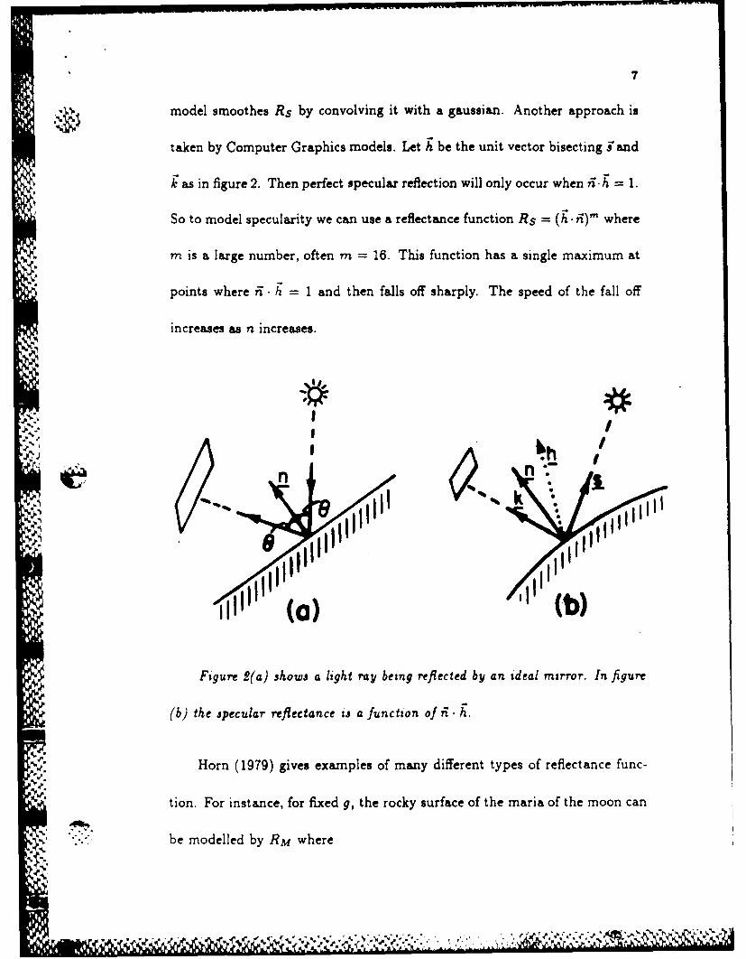
model smoothes Rs by convolving it with a gaussian. Another approach is
taken by Computer Graphics models. Let K be the unit vector bisecting "and
k as in figure 2. Then perfect specular reflection will only occur when ii. h = 1.
So to model specularity we can use a reflectance function Rs = (h' i)' where
m is a large number, often m = 16. This function has a single maximum at
points where ii h. = 1 and then falls off sharply. The speed of the fall off
increases as n increases.
I#
n n
( J
Figure 2(a) shows a light ray being reflected by an ideal mirror. In figure
(b) the jpecular reflectance ij a function of ii h.
SHorn (1979) gives examples of many different types of reflectance func-
tion. For instance, for fixed g, the rocky surface of the maria of the moon can
be modelled by RM where

8
v.:
cos(i)RM - ose (2.3)cose)
This has the interesting property that if the source of illumination is
directly behind the viewer, so that i = e, the surface will be of constant
brightness. This effect is easily observed when the sun, earth and moon are
appropriately aligned.
A crucial problem for shape from shading concerns the uniqueness of the
solution. Even if the light source direction is known there is one equation
for two unknowns, the two independent coefficients of the surface normal, at
each point. Thus simple number counting suggests that more information is
needed to guarantee uniqueness. Uniqueness results are discussed further in
section 5.
There have been disappointingly few psychophysical experiments inves-
tigating shape from shading. In recent work Todd and Mingolla (1983) dis-
played the images of cylindrical surfaces of different radii and asked subjects
to estimate the curvature. They showed that humans were able to get a weak
estimate of the surface shape and were better at finding the light source direc-
tion. Adding some texture patterns, to allow shape from texture, improved
their performance. Specular highlights did not seem to influence these results.
This work is very preliminary and more research is needed in this area.

It has been found empirically (Woodham 1980) that the Lambertian is
a suprisingly good model for many aerial photographs. However there are a
number of atmospheric effects (Sjoberg 1982) which must be taken into ac-
count. A recent report (Woodham and Lee 1984) concludes that atmospheric
effects, such as the scattering of the direct solar beam, are important and
vary locally with elevation. The sky irradiance is also significant and must be
modelled explicitly.
3. Gradient space and characteristic strips
An important issue for all vision problems is the choice of representation.
Workers in shape from shading have often used a representation for surfaces
known as Gradient space. This was developed by Huffman (1971) and Mack-
worth (1973) in another context. It was first used for shape from shading by
Horn (1977).
We choose a coordinate system such that the image lies in the xy plane.
An arbitrary point on a surface z = f(x, y) is given by
(X (.,y,f(x,y)). (3.1)
The surface normal is
~~~~~~~............. .. .. :........... ... .... ............ ,..-..............-...........,..-
10
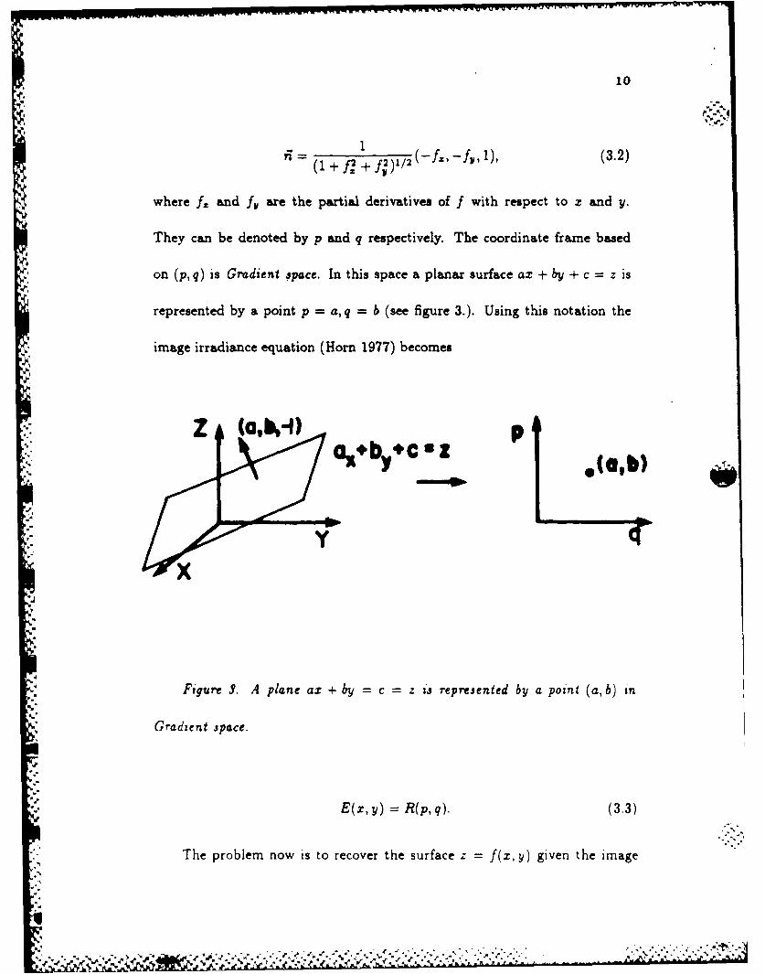
- 1 (3.2)
where f2 and fl, are the partial derivatives of f with respect to x and y.
They can be denoted by p and q respectively. The coordinate frame based
on (p, q) is Gradient ;pace. In this space a planar surface ax + by + c = z is
represented by a point p = a, q = b, (see figure 3.). Using this notation the
image irradiance equation (Horn 1977) becomes
Figure S. A plane ax + by =c =z is represented by a point (a, b) in
Gradient space.
E(x,y) =R(p,q). (3.3)
The problem now is to recover the surface z f f(z, y) given the image
-k -A .;z.

11
intensity E(z, y) and the form of the reflectance function R. Figure 5 shows
contours of constant intensity as a function of p and q for a specific reflectance
function. Many reflectance functions can be expressed simply in terms of
Gradient space. For example it is easy to verify that the reflectance function
of the maria of the moon RM, given by (3.3), is a linear combination of p and
q.
q-q
• .9
i "-..s.0.7
Figure ,4. Contours of constant intensity in Gradient space.
Gradient Space has a serious disadvantage which we will discuss in more
detail in section 4. At occluding boundaries both f. and f, become infinite
and so p and q are undefined although the surface normal is well behaved.
Thus the coordinate system breaks down at occluding boundaries. These
boundaries are often important as boundary conditions for variational shape
12
from shading.
The image irradiance equation (3.3) is a non-linear, first-order partial
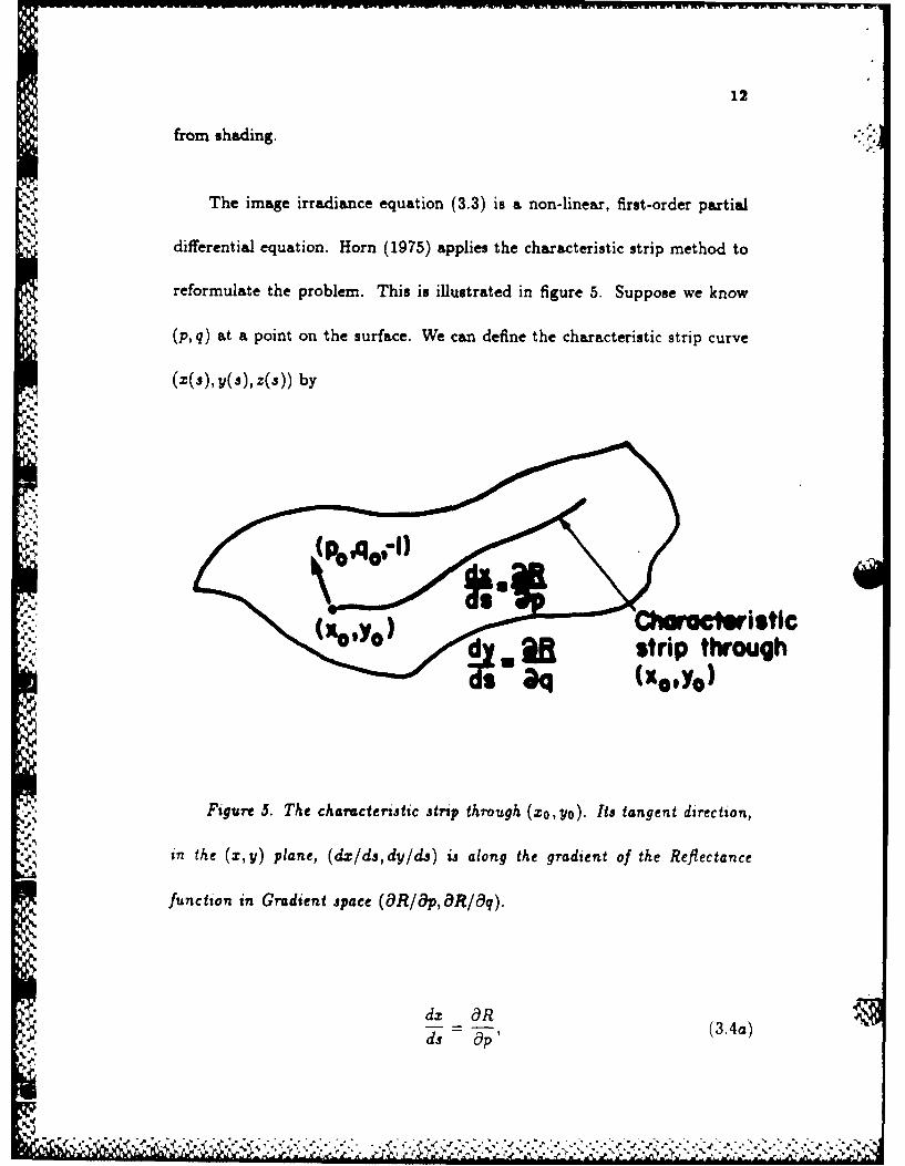
differential equation. Horn (1975) applies the characteristic strip method to
reformulate the problem. This is illustrated in figure 5. Suppose we know
(p, q) at a point on the surface. We can define the characteristic strip curve
(x(s), y(s), z(s)) by
(%VYO geestrip through~(Xo9y o)
Figure 5. The characteristic strip through (xo,yo). Its tangent direction,
i. n the (x, y) plane, (dx/d, dy/ds) is along the gradient of the Reflectance
function in Gradient space (8R/8p,8 R/8q).
dx 8R (34)ds - p (3.4a)
13
dy _ Rdy = - (3.4b)ds aq '
_dz 8R 8Rd=z P + q a. (3.4c)
Note that the dot product of the tangent to this curve with the surface
normal i ,given by (3.2), is zero. Thus the curve lies on the surface. In terms
of p and q this becomes
dx dy dzd- . (3.5)
Differentiating eq. (3.3) with respect to x gives
Ex = RppZ + Rqqz. (3.6)
Since p.=f = q, we find
Ex = Rppz + Rqpy (3.7)
and so, using eq. (3.4), we get
E.= dp. (3.8)ds
Similarly
iI
14
E = ' (3.9)
These equations can be used (Horn 1975) as a basis for an iterative com-
putation. Suppose the surface gradient (p0, qO) is known at a point (xo, yo).
We can find the tangent to the characteristic strip at this point from eq. (3.4).
Using the intensity gradient we can use (3.8) and (3.9) to calculate dp/ds and
dq/ds. Thus we can determine the gradient (pi, qj) at (x1 , yi). Repeating this
procedure we can calculate p and q along the characteristic strip curve. The
set of all characteristic strips will span the surface. So if we know the surface
normal on one point on each characteristic strip we can use this method to
recover the surface.
The characteristic strip method has several disadvantages. It needs the
surface at the initial point to be convex, it is complex to compute and it is
very susceptible to noise. In addition the surface normal at the initial point
for each characteristic strip must be known. Another problem is the possible
non-uniqueness of the inverse shape from shading calculation. It cannot be
guaranteed that the strips method will converge to the right answer. From
the perspective of human vision .the serial nature of the computation makes
it biologically implausible.

15
4. Geometric assumptions and Photometric stereo
An alternative approach to shape from shading is to restrict the surface ge-
ometry. The simplest situation is a world of planar surfaces. Horn (1977)
showed that if three planes meet at a point then the orientation of the planes
can be determined locally by shading information.
(a) M
Figures 6(a) and (b) show two developable surfaces.
Woodhar (1981) extends this result to the class of developable surfaces,
which includes cylinders and cones. These surfaces are defined so that for
every point on the surface there is a straight line ruling through it along
which the normal vector is constant, see figure 6. Since the reflection func-
tions depend only on the surface normal the image intensity will therefore be
constant along these rulings. Thus it is straightforward to check directly from
16
the image if a surface is developable. For these surfaces the characteristic
strips method, and other more numerically stable techniques, can easily be
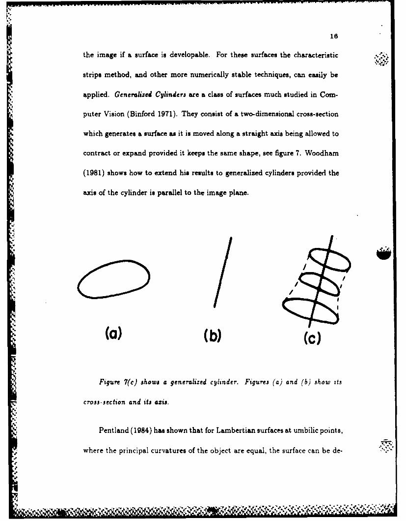
applied. Generalized Cylinders are a class of surfaces much studied in Com-
puter Vision (Binford 1971). They consist of a two-dimensional cross-section
which generates a surface as it is moved along a straight axis being allowed to
contract or expand provided it keeps the same shape, see figure 7. Woodham
(1981) shows how to extend his results to generalized cylinders provided the
axis of the cylinder is parallel to the image plane.
,<:J/ ,
(a) (b) (c)
Figure 7(c) shows a generalized cylinder. Figures (a) and (b) show its
cross-section and its axis.
Pentland (1984) has shown that for Lambertian surfaces at umbilic points,
-y...where the principal curvatures of the object are equal, the surface can be de-
.J4

17
termined locally. This result is limited as the sphere is the only curved surface
which is umbilic everywhere and there is no known method of discovering if
the surface is umbilic or not. Nevertheless Pentland argues that this require-
ment can be relaxed and reports good results from this method even when
the surface is not umbilic.
Perhaps the most elegant method of using shading information is pho-
tometric stereo (Woodham 1978, 1980). Here the direction of incident illu-
mination is varied between two successive views. We denote the two images
by E,(x. y) and E 2(x, y) and let the corresponding reflectance functions be
Ri(p, q) and R 2 (p, q). If the illumination is rotated about the viewing direc-
tion then R 1 and R 2 are simply related. The two views yield the equations
E, (x,y) = R,(p,q) (4.1a)
E 2 (X, Y) = R 2(p,q) (4.1b)
in the two unknowns p and q. These will usually be sufficient to determine the
shape. At any point (x1 , yj) the first image will constrain p and q to lie on the
contour R,(p, q) = E,(x 1 , yj) in Gradient Space. Similarly the second image
will constrain them to lie on the contour R 2 (p, q) = E 2 (zl, Wi). These curves
will usually intersect in two points allowing at most two consistent surface
18
gradients. If necessary a third image E3 could be used.
Photometric stereo can be easily implemented (Silver 1980) and is proba-
bly the most practical method of doing shape from shading. It can be speeded
up by using a lookup table to attain real-time performance.
5. Variational Methods
We mentioned earlier the disadvantages of the characteristic strips approach
to solving the image irradiance equation. In this chapter we show how to
formulate shape from shading as a minimization problem which can be solved
by local parallel processors. These methods are numerically stable and only
require a single view. They usually achieve this stability by making smooth-
ness assumptions about the viewed surface. To attain uniqueness they need
to know the surface normals on the boundary of the object, see figure 8. For
occluding boundaries this information can be found directly from the image
(Barrow and Tennenbaum 1981, Ikeuchi 1980). At such boundaries the nor-
mals are perpendicular to the projection direction and hence lie perpendicular
to the projection of the occluding boundary.
V. The first parallel scheme was due to Strat (1979). It used the gradients
p,q to express surface orientation and was therefore i;nable to deal with oc-
.1 .

19
cluding boundaries. It was not formulated as a variational problem, but Horn
and Brooks (1985) show that it can be expressed in these terms.
l~ccluding
Boundarysmoothness
Figure 8. Variational methods assume knowledge of the normals on the
boundaries, the image irradiance equation (Lambertian in this case) and sur-
face smoothness.
Ikeuchi and Horn (1981) developed another method using the calculus of
variations and an alternative coordinate system. In terms of Gradient Space
coordinates the surface normal is
(1 + (-p-q, 1), (5.1)
At occluding boundaries p and q become infinite although the normal
itself is well behaved. Ikeuchi and Horn (1981) suggest using coordinates f
L W 4L..

20
and g given by
2p1 (1 + p2 + q2)1/2 (5.2a)
2qS +(1 p2 + q2) 2 (5.2b)
These coefficients satisfy f 2 + g2 < 4 for all visible parts of a surface.
This stereographic space corresponds to projecting the Gaussian sphere of all
possible surface orientations onto the plane from its north pole. In contrast
gradient space corresponds to a projection from the centre.
In terms of these coordinates the image irradiance equation becomes
E(x, y) = R(f,g). Let Ql be the region on which the image is defined. We
define a measure of the brightness error by
j(E(xy) - R(f(x,y),g(x, y))) dxdy. (5.3)
The minimization of the brightness error does not constrain the problem
sufficiently. For generic surfaces we expect that neighbouring points will have
similar orientations. To impose this Ikeuchi and Horn (1981) add a smoothness
term given by
J (fi + f 2y -)dzd,.(.)
YI

21
"N This smoothness term will be small for a surface with few fluctuations
in f and g. Adding the smoothness error to the brightness error we obtain a
functional
J jE(x, y) - R(f (x, y), g(x, y))) ' + A(f.1 +f2 + g2 + g2)dxdy. (5.5)
This functional is minimized with respect to f and g over the space
Q, subject to the boundary conditions. X is a scalar that assigns a relative
weighting to the terms.
It is a standard result of the Calculus of Variations (Courant and Hilbert
1953) that, in most situations, minimizing the functional (5.5) is equivalent
to solving the associated Euler-Lagrange equations
t (E - R)R! + AV 2f = 0, (5.6a)
(E - R)R, + AV2g = 0. (5.6b)
Here Rf and R. are the partial derivatives of R(f, g) with respect to f
and g and
, ' 8V_0 2
(9X2 OX-2
22
is the Laplacian operator. These equations can be solved by a finite difference
approach. The Laplacian is written as
~~~(V f),j = 4(, ,) (5.8)4-
(V~f ,2 (7 - (5.8)
where E is the grid spacing and the local average f7i is given by
Tj = 1 Y6+1 + fi+i,j + fi,j-. + fi-l,,). (5.9)
We can rewrite the Euler-Lagrange equations in this form
= - E2
+ ¥ (Ei3 - R(f1 j, gi))Rf(f , , g,.7), (5.10a)
9ij= §1+ (Eij - R(fi,gi,))R(fj,gij), (5.10b)
These equations can be solved using an iterative scheme
-- E 2
f,,+' = f + " (E), - R(f,,,g,))R(f,),,1,) (5.11a)4A
E2k+ = + (E - R(fI g,,,))R,(fI 3 . g ) (5.11b)
Empirical results demonstrate the effectiveness of this scheme although
there is no proof to guarantee that it will converge to the correct solution. The
iIzZ49,M

23
scheme is intrinisically parallelbsable. There are several alternative methods
to minimize the cost functional including the gradient descent technique.
The smoothness term is necessary to ensure a well-defined smooth solu-
tion. However it does tend to bias the resulting surface. For example if the
image corresponds to a sphere the algorithm will yield a distorted sphere. The
amount of this distortion depends on the size of the parameter A. This pa-
rameter must be large enough to make the algorithm stable and small enough"S
'not to distort the surface too much.
A weakness of this scheme is that it treats f and g as being independent
variables and makes no use of the integrability constraint (Brooks 1982). This
constraint '-ises because of the "consistency" of the surface and corresponds
to the condition f., = fy. In terms of gradient space it is expressed as
Py = qX. (5.12)
We can use (5.2) to write this in terms of f,g and their derivatives.
However it is too complicated to be easily used to constrain the solution.
Strat's method (1979) implicity uses this constraint although his method
is based on an integral form. The scheme can be posed in a functional form
(Horn and Brooks 1985) and does not include a smoothing term. Horn and
Brooks 1985) describe his work and provide a summary of other work on
. '"

24
variational approaches to shape from shading,
All these approaches assume that the source direction is known accu-
rately, which is unlikely for most realistic situations. To deal with this problem
Brooks and Horn (1985) have proposed an iterative scheme using a variational
principle that estimates the source direction as it determines the slope. There
is no guarantee of convergence of the algorithm but preliminary implementa-
tions are encouraging.
6. Uniqueness
Bruss (19ol) has obtained some results about the uniqueness of the image
irradiance equation. She assumes the light source is known and shows that
boundary information, usually in terms of occluding contours, is almost always
needed. She considers reflectance functions of form f(p 2 +q 2 ), where f is a one-
to-one function. She shows that if the behaviour on the boundary is specified
and Ez, y) has at most one stationary point then the solution is unique up to
inversion. A special case of this reflectance function is a Lambertian surface
with the light source directly behind, or over the shoulder, of the vev;er.
More recently several proofs have been proposed to prove uniqueness Lor
Laiibertian surfaces with general viewpoint (Baddoura 1985, Blake 1965b,
.6

25
Yuille and Brady 1986) assuming the normal vector on the boundaries is
known. Although these proofs are interesting in their own right none of them
suggest new algorithms to calculate shape from shading.
If the direction of the light source is unknown there is additional ambi-
guity (for example see Woodham 1981) and uniqueness results might seem
even harder to obtain. Suprisingly this is usually no: the case (Yuille and
Brady 1986). If the normal to the surface is known then given the form of the
reflectance function it is often straightforward to determine its parameters.
For example, the Lambertian reflectance function is given by
E(x,y) = . ii (6.1)
and is specified by three parameters, the coefficients of i. If the boundary
, is occluding then the surface normal ii is known there. Hence for a typical
object there are an infinite number of equations, although they may not be
independent, from which to determine .1, see figure 9. These may still not give
sufficient information as the surface normals at occluding boundaries generally
are perpendicular to the viewer direction k. In this case two coefficients of
can be found but the coefficient in the k direction is unknown. Suppose,
however, we make the reasonable assumption that there is a point at wh;ch
the surface normal points directly to the light source. This point can be
iia%
-* "e P. e

26
easily found since, by (6.1) it will be a global maxima of the image intensity.
Moreover the value of the image intensity at that point will be the modulus
of i. It is now straightforward to determine the third component of i This
argument does not apply to the example of Woodham (1981) which was a
cone and because of its regular structure had no normal pointing towards the
light source. This proof can be extended to more general reflectance functions
and combinations of them (YuiUe and Brady 1986).
"..'2' I
''
In figure 9(a) there are an infinite number of directions of the surface nor-
mal i and hence an infinite number of equations. However if the reflectance
i i s Lam bertian there will be only two independent equations. In figure (b) there
i s only one equation.
This argument helps for uniqueness proofs but may not yield a stable
S. ).
I-.

27
method to determine the source direction for real images. Moreover the ap-
proximations used to model objects as Lambertian surfaces may not hold near
occluding boundaries.
7. The Extended Gaussian Image
- In order to recognize an object and determine its orientation in space it is
necessary to have a way of representing its shape. One such representation
which has been proposed by Horn (1982, 1984) is the extended Gaussian Im-
Aage. Because it explicitly represents shapes by their surface normals it seems
particularly appropriate for describing objects found by a module like shape
from shading which calculates orientation rather than depth. Each point on
the object is represented by a point on the Gaussian sphere corresponding
to the direction of the surface normal, see figure 10. If several points on the
object have the same surface normal then each such point contributes a unit
of "mass". Thus the extended Gaussian sphere representation of an object
consists of a mass distribution on the sphere. The total mass of the sphere
corresponds to the total surface area of the object. It can be shown that this
representation is unique for convex objects. This representation stays invari-
ant under translation of the object and behaves simply under rotation, the
.4 ,,ea . .' . . . ,%,.. e%

28
whole sphere rotates by the same amount.
/ z•/*
,. Figure 10. The unit normal to the surface at a point is parallely trans-
ported so that its base lies at the centre of the Gaussian sphere. The point
i3 represented by the position of the tip of the normal on the surface of the
sphere. Note that the coordinates of the point in Gradient space are given by
the intersection of the line along the normal with the plane z = I at the top
of the sphere.
IL 8. Applications
In this section we discuss two important uses of shape from shading. We first 'F..
consider using the image irradiance equation to predict the image of a given
lPhi

29
screen for aerial photography. Secondly we describe work in which a robot
uses shape from shading to pick an object out of a bin of parts.
The study of aerial photographs is a growing application area of shape
from shading. For example it is important to monitor areas of harvesting
activity. In rugged terrain changes, i.a image irradiation due to the ground
cover are often dominated by chaiges due to variations in the topography. If
the variations in topography can be predicted, then the remaining variations
can be interpreted as changes in ground cover and used to determine the state
of the harvest. For aerial photography the sun is the unique light source and
its exact direction can easily be determined.
The reflectance map can be used to synthesize a model for the variations
4 due to topography. No attempt is made to invert the map. Instead the
surface slope information is used as input to the image irradiance equation
which then predicts the intensity for a given illuminant and viewer. It is
necessary to have good determination of shadow information, which typically
correspond to occluding boundaries. For aerial photographs, and Landsat
images, the primary light source is the sun and its postion must be accurately
known at the time that the satelite takes its pictures.
It has been found empirically (Woodham 1980) that the Lambertian is
a suprisingly good model for many aerial photographs. However there are a
N N I.%,; " --.-. %-, % %,o %/..- . - . . .,4o e. X! I ". . , .¢ . , . . _.....

30
number of atmospheric effects (Sjoberg 1982) which must be taken into ac-
count. A recent report (Woodham and Lee 1984) concludes that atmospheric
effects, such as the scattering of the direct solar beam, are important and
vary locally with elevation. The sky irradiance is also significant and must
be modelled explicitly. This leads to a scene irradiance equation with three
terms
'a. L+ ((g))coS(i)+-) (1 + cos(e)) +'1H
r 7r 2 +Pe'II
(8.1)
where r(z) = re- z/ / . These three terms correspond to solar irradiance,
sky irradiance and path radiance respectively. E, p, r, Eso, Hs, Lpo and H
are constants.
In re'ated work Horn (1981) argues that digital terrain models provide
convenient surface descriptions for use in the study of hill-shading for maps.
They can also be used for the automatic registration of satellite images with
: surface models (Horn and Bachman 1978).
Shape from Shading is a practical tool in industrial situations since it is
often possible to control the lighting. The reflectance characteristics of the
viewed objects are also known. Techniques like photometric stereo can then be
employed to find the orientation values of objects. An example is work done
a,
31
by Horn, Ikeuchi et al (Ikeuchi et al 1984, Horn and Ikeuchi 1984) linking a
Puma robot with a vision system which makes use of photometric stereo.
9. Photometric Invariants
Another branch of research tries to find what can be extracted from the in-
tensity without explicit knowledge of the reflectance map but merely its func-
tional form. More precisely use is made of the fact that the reflection function
depends on the geometry of the surface only through the surface normal.
We first need some concepts from differential geometry (Do Carmo 1976).
At every point on a surface there are two orthogonal directions in which the
curvature of the surface changes most. These are called the principal direc-
tions of curvature. The curvatures in these two directions are the principal
curvatures. These properties are independent of the orientation of the surface.
The product of the principal curvatures is the Gaussian curvature, see figure
11. If the principal curvatures are of opposite sign the Gaussian curvature is
negative and the surface is hyperbolic. An example of a hyperbolic surface is
a saddle point. If the principal surfaces have the same sign the Gaussian cur-
vature is positive and the surface is elliptic. Regions of positive and negative
curvature will be seperated by lines with zero Gaussian curvature. These are
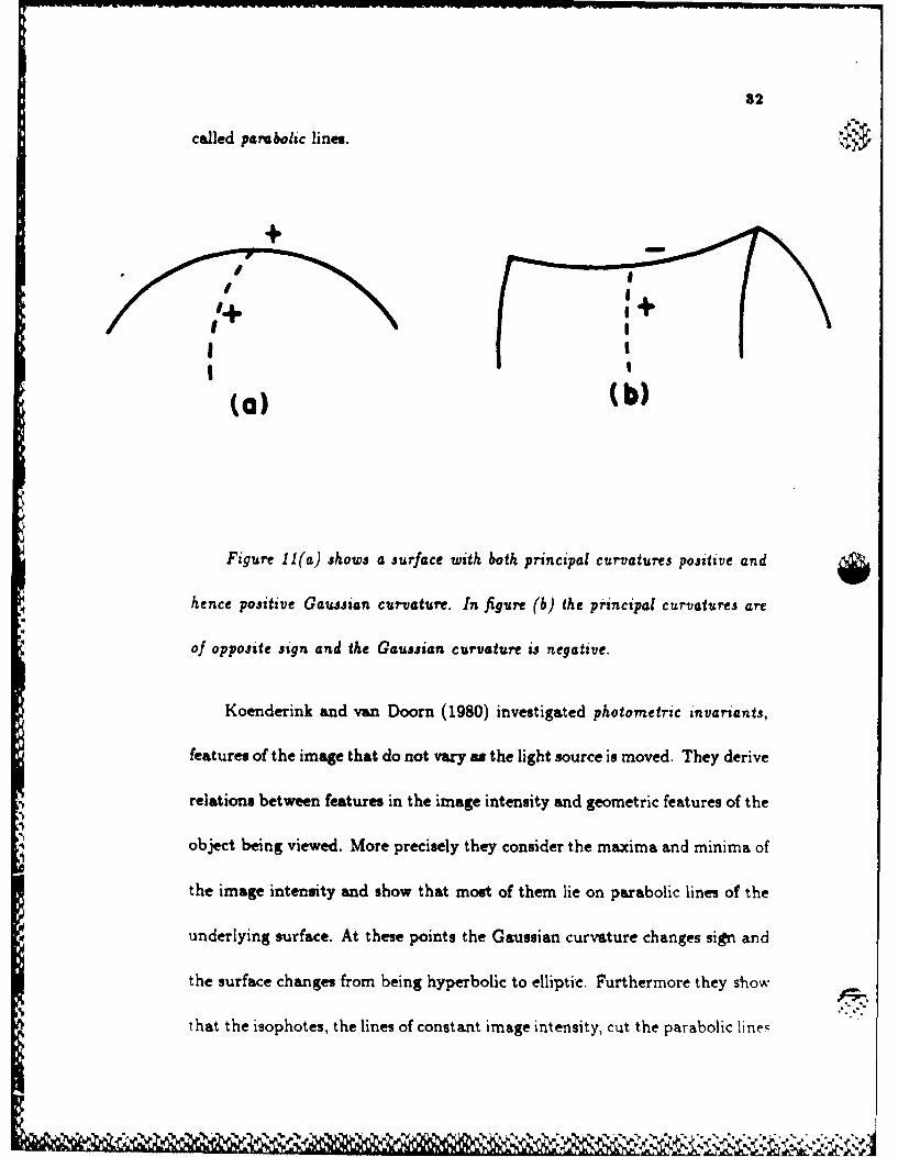
32
called parabolic lines.
I+
" II I
(a) (b)
Figure 11(a) shows a surface with both principal curvatures positive and
hence positive Gaussian curvature. In figure (b) the principal curvatures are
of opposite sign and the Gaussian curvature u negative.
Koenderink and van Doom (1980) investigated photometric invariants,
features of the image that do not vary as the light source is moved. They derive
relations between features in the image intensity and geometric features of the
object being viewed. More precisely they consider the maxima and minima of
the image intensity and show that most of them lie on parabolic lines of the
underlying surface. At these points the Gaussian curvature changes sign and
the surface changes from being hyperbolic to elliptic. Furthermore they show
that the isophotes, the lines of constant image intensity, cut the parabolic lines
'v'p.
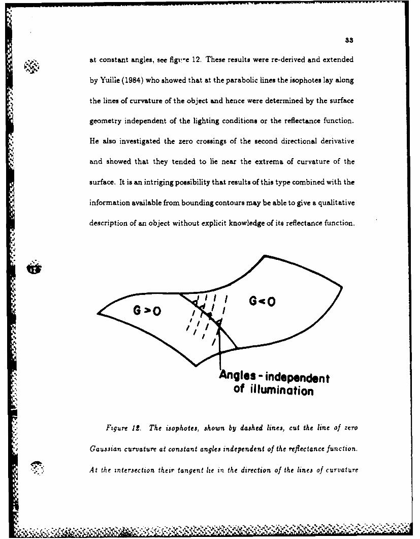
33
at constant angles, see figu,-e 12. These results were re-derived and extended
by Yuille (1984) who showed that at the parabolic lines the isophotes lay along
the lines of curvature of the object and hence were determined by the surface
geometry independent of the lighting conditions or the reflectance function.
He also investigated the zero crossings of the second directional derivative
and showed that they tended to lie near the extrema of curvature of the
surface. It is an intriging possibility that results of this type combined with the
information available from bounding contours may be able to give a qualitative
description of an object without explicit knowledge of its reflectance function.
J
Angles - independentof illumination
Figure 12. The isophotes, shown by dajhed lines, cut the line of zero
Gaujsian curvature at constant angles independent of the reflectance function.
* , .At the intersection their tangent lie in the direction of the lines of curvature
" , . . .. . . . . . -- -. - - " . " " " " " " ", " . " ''. u. ' ,' u " ' ." ," ''" ' .'. - ' ""

34
of the surface.
10. Computer Graphics
Present theories of shape from shading only work in restricted lighting condi-
tions for objects with simple reflection functions and it is unlikely that they
can work for general scenes. It may, however, be possible to use shading in-
formation to obtain qualatative information about objects. The reflectance
models of Computer Graphics could be the basis for such a theory.
In recent years there has been considerable interest in modelling real
scenes with Computer Graphics. For realistic effects the reflectance functions
of objects must be modelled exactly. Films like "Tron" show how effective
present techniques are.
The reflectance function concept was introduced into Computer Graph-
ics by Phong (1975). He suggested modelling the reflectance function as a
combination of Lambertian and Specular components. This is given by
Rp = Cp(cos(l)(1 - d) + d) + W(i)(cos(s))R (10.1)
where CP is the reflectance coefficient of the object, d the environment diffuse
reflection coefficient and W(i) is a function giving the ratio of the specular
.3 ,dye,

reflected light to the incident light. Blinn (1977) introduced the lighting
models of Torrance and Sparrow (1967) which modelled the surface as a set
of planar facets with specular components and a diffuse component due to
multiple reflections. This work was extended by Cook and Torrance (1982)
!who emphasized the wavelength dependence of reflectance. Intuitively an
object reflects light either at the surface, in which case the reflectance is
, ftspecular and the wavelength is independent of the material, or below the
surface. In this case the reflected light depends on the object and can often
be assumed to be Lambertian. Metals are good conductors of electricity and
so the electromagnetic field of light does not penetrate them far. Thus their
.reflectance functions have mostly specular components.
An important effect described by these models is off-specular reflectance.
This occurs when light is incident from a non normal direction. A maximum
in the distribution of the reflected radiance occurs at an angle larger than the
specular angle.
% The Cook and Torrance model assumes that the reflectance is a sum of
three components: specular, diffuse and ambient. The ambient and diffuse
td .*. components reflect light in all directions equally. The specular reflectance is
lit F DGR, (10.2)
7 (N. L)(N .V)
I-.

36
The geometrical attenuation factor G accounts for the shadowing and
masking of one facet by another (Blinn 1977). The facet slope distibution
function D represents the fraction of facets that are oriented in the direction
H (Blinn 1977).The Fresnel factor F depends on the reflectance spectra of the
material and is a function of wavelength. These functions are complex and
often need to be determined by experiment (see Gubreffet al 1960). In general
F depends on the geometry of reflection and hence the colour varies with
direction. For example for copper the colour of the reflected light approaches
the colour of the light source as the incident angle approaches 7r/2.
A typical plastic has a substrate that is transparent or white, with em-
bedded pigment particles. Thus the light reflected directly from the surface
is only slightly altered in colour from the light source. This is well modelled
by Phong and Blinn. The more complex model of Cook and Torrance is also
suited for modelling plastics. Moreover it also produces realistic metals, unlike
many computer graphics which tend to make everything seem plastic.
Many surface materials in the natural world are anisotropic, for exampte,
cloth is a weave of threads each of which scatters light narrowly in the direc-
tion of the thread and widely in the perpendicular direction. It is relatively
straightforward to generalize the Phong model to get anisotropy.
There has been comparatively little work inverting these models to get

3T
shape, or other information. An interesting exception is the work of Shafer
(1984) who proposes using colour vision to distinguish between the lambertian
and specular components. He models reflectance by a combination of interface
("specular") and body ("diffuse") reflections. These have different specular
behaviour and he describes a method of using colour to separate the reflection
into its interface and body components. This gives a possible solution to the
old vision problem of extracting the specular components of an image.
11. Occluding Boundary Information
It has long been known that occluding boundaries give a lot of information
about the shape of objects. Picasso's picture "The Rites of Spring" gives a
strong impression of shape despite the paucity of information (Marr 1977), see
figure 13. Marr argued that the visual system needed to make assumptions to
interpret these contours and, in particular, he proposed that the distinction
between convex and concave segments reflected real properties of the viewed
surface. He assumes that there are no invisible occluding edges. He claimedI'
that these assumptions could only be satisfied if the perceived boundary rim
was planar. This is a very strong assumption and recent results by Koenderink
have shown it to be unneccessary. Using it Marr was able to show that if it held
!p
,.1- ;l , :; i i ; ,2. . ?., Z? . : '..-. .' . .-.-.. ,.. . ... .. . ,.......

38
for all views of an object about a given axis then the object was a generalized
cylinder (Binford 1971) about that axis.
Figure 13. The Rites of Spring
The boundary contour, or silhouette, is the projection of the boundary
onto the image plane. The points on the object which give rise to the bounding
contour are called the boundary rim. At these points the light rays just grue
the surface of the objects. If we assume orthographic projection onto a plane
.4- with surface normal i then the equation of the boundary rim is given by
i~i=O0. (11,1)
where ii is the normal to the surface. This equation only holds for occluding
boundaries where the surface turns away smoothly from the viewer. This
. . . . o . . . ...
a..F 39can be contrasted with discontinuity boundaries, for example the boundary
of a sharp knife. Barrow and Tennenbaum (1981) observed that for occluding
boundaries the normals at the boundaries can be easily determined. The x, y-.
components are available directly from the image and from (9.1) we see that
the z component vanishes. This result can be used to get boundary conditins
for shape from shading.
Koenderink and van Doorn (1982) consider the way the projected con-
tours of smooth objects end. They show there are a small number of rules for
the way contours in the image can disappear. These results can be deduced
from a more general theorem proved by Koenderink (1984). This result states
that the sign of the curvature of the projected curve is equal to the sign of
the Gaussian curvature of the object at the boundary rim, see figure 14. This
is true for both orthographic and perspective projection. This result means
that concave and convex segments on the curve do correspond to meaningful.' .-%
properties of the surface as Marr (1977) claimed, but that the planarity as-
sumption is unneccessary. It is clear that contours can only end when they
correspond to negative curvature of the surface. In this case the projected
curve must be concave at the endpoint.
V4

40
of the bounding contour. This is true for both discontinuous and occluding
boundaries. An application is for developable surfaces for which at each point
on the surface there is a straight line ruling through it along which the surface
normal vector is constant. It can be used for looking at developable surfaces
to obtain an estimate of the sign of the non-zero principal curvature.
.180
' II
I, /I,
Figure 14. Points with zero Gaussian curvature, G = 0, are projected to
points with KP = 0. Hence the sign of the Gaussian curvature of the boundary
rim is equal to the sign of the curvature of the projected curve.
An interesting application of these results is the folding hankerchief the-
orem. A hankerchief is a surface which tends not expand or contract locally
as it is folded. Thus its Gaussian curvature remains zero. Therefore
occluding boundary must project to a straight line in the imago
41
, ~ Preliminary work by Richards et al (1985) questions how we can predict
what 3D objects correspond to 2D shape. They assume you are given a view
of an object which they call generic; one in which all the significant events
in an object which could cause occluding contours do in fact do so. This
means that some objects do not have generic views. They represent surfaces
by the Gaussian sphere and folds on the Gauss map correspond to the surfaces
7 changes the sign of the Gaussian curvature. They propose rules of preference
for choosing between possible ambiguous interpretations of the Gauss map.
-U.
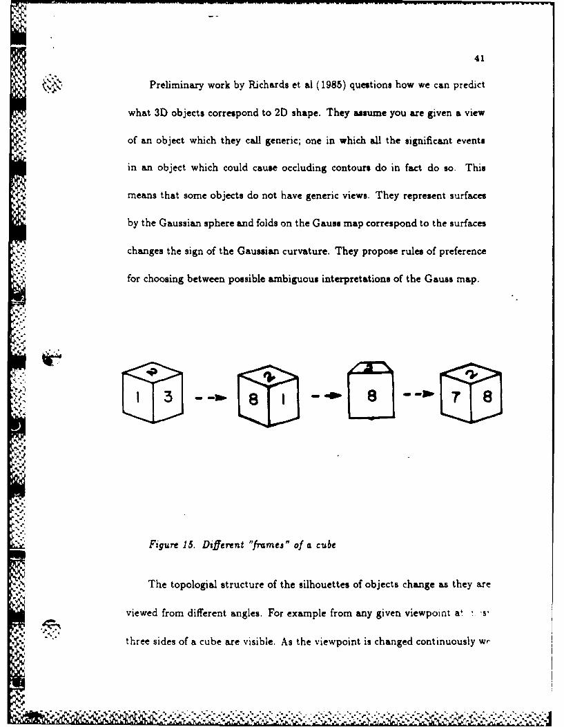
Figure 15. Dsfferent "fmes" of a cube
The topologial structure of the silhouettes of objects change as they are
viewed from different angles. For example from any given viewpoint at . s'
three sides of a cube are visible. As the viewpoint is changed continuously wr
42
switch to seeing three different sides, see figure 15. There are eight possible
sets of three sides that can be seen at the same time. These sets corresplond to
tile eight different Frames of the cube (Minsky 1975). Similarly the bounding
contour of any object will vary with the orientation of the viewer. As the view-
point changes cusps, convexities and concavities can appear and disappear.
As these changes occur the "topology" of the silhouette alters. Koenderink
aiid van Doorn (1985) use catastrophe theory to describe and classify these¢,
changes. With these techniques an object can be classified by the different
topologies of the silhouettes it displays.
..." 12. Shape frow Texture
4.,-As
#0i Somne texture pat terns can yield an extremely strong perception of depth. This
5%J
effect has long been known by artists. The phenomenon was investigated
by Gibson (1950) and his school and many striking demonstrations of the
effect were found. Most of the theoretical analyses, however, were limited and
usually restricted to texture gradients on horizontally extended planes.
Most recent work assumes that primitive texture elements can be ex-
tracted from the image. These elements are characterized by a set - )arp'
eters. These parameters can be determined from the image a ,i,, local
'A ', ', . . .... ... -r - '. 2 1... .

43
constraints on the surface orientation. For example the elements could be
the small circular holes on a golf ball. see figure 16. In the image these holes
would appear as ellipses whose size and orientation determine the local sur-
face orientation. Once constraints on the local surface normal are known the
surface itself can be constructed by interpolation. Ikeuchi (1980) described
and demonstrated an algorithm of this type. It has many parallels to his work
()., shape from shading.
eo9oooooo0 0oo0 0 Co-
: ,!i~ 0 0 0° 0 0 0/'ooooo o:0 000 0
Figure 16. The'regular spacing of the holes of a golf ball give an example0 %..
of shape from texture.
Ikeuchi makes four assumptions. (1) The surface is covered with a uni-
form texture of repeated texture elements. (2) Each texture element is small,
- "" compared with the distance between the viewer and the viewed surface. (3)
WI,-
44
Each texture element is small, compared with the change of surface orientation
there. (4) The original shape of the texture element is known.
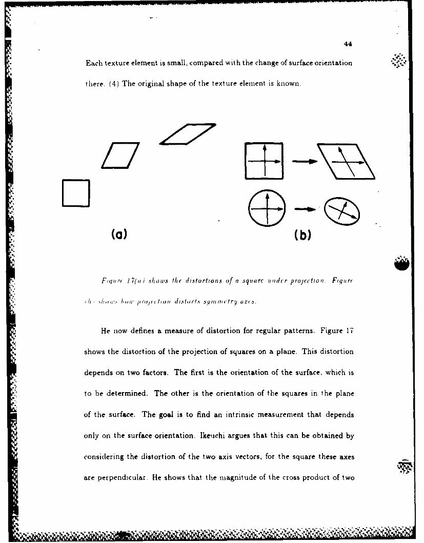
~/17
io .(a) (b)
Fiqur, 17(11; shows the distortions of a squiarc iudcr proJcctioi. Figurc
;b t,,I.% /11, , e ' to, dlstrt., s ,mn m t r axf-s.
He now defines a measure of distortion for regular patterns. Figure 17
shows the distortion of the projection of squares on a plane. This distortion
depends on two factors. The first is the orientation of the surface, which is
to be determined. The other is the orientation of the squares in the plane
of the surface. The goal is to find an intrinsic measurement that depends
only on the surface orientation. Ikeijchi argues that this can be obtained by
considering the distortion of the two axis vectors, for the square these axes
are perpendicular. He shows that the magnitude of the cross product of two
45
.. .. ,,, axis vector projections is proportional to cos, and the sum of squares of their
lengths is proportional to 1 4- cos 2 , where , is the angle between the direction
of the viewer and the direction of the surface orientation. These two values
are independent of the rotation angle of the regular pattern. For spherical
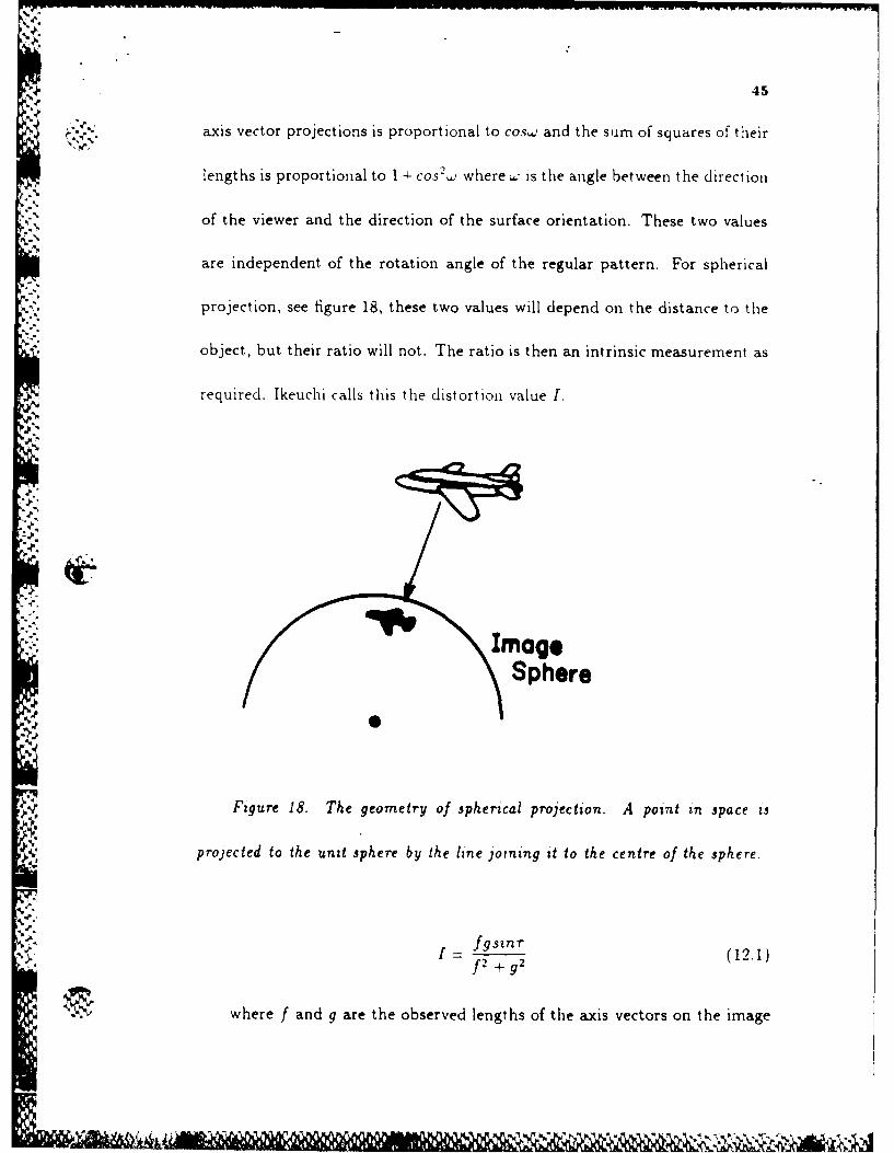
projection, see figure 18, these two values will depend on the distance to the
object, but their ratio will not. The ratio is then an intrinsic measurement as
required. Ikeuchi calls this the distortion value I.
-4.
ImageSphere
Figure 18. The geometry of spherical projection. A point in space Is
projected to the unit sphere by the line joining it to the centre of the sphere.
r4.-
-,fgsn(r
f2 + g2
.• where f and g are the observed lengths of the axis vectors on the image
AMN 6-,Q'
46
sphere and T is the angle between the two projected axis vectors. These . A .
qualities f, g and 7 can be directly ineasued fron the image. Ili ternis of
surfaces rotation
COSW, (12.2)
where , is the angle between the direction of the viewer and the surface
normal. These equations eliminate one degree of freedom of the surface, in
this sense they are similar to the image irradiance equation in shape from
shading. Several strategies can be used to solve for the final degree of freedom.
One positility is to take two, or more. vie d' t" l" ext Ired surface, this
iz 'ougli.v analog,,us to doing photometric si e,. A.,n)ther appi)ach is to
use a .sil Utlhmiess constraint requiring that igl i boniing 1,,inls lm ave nearly
the same orientation. This is similar in spirit to the variational approach
to shape from shading. Ikeuchi defines an iterative algorithm to solve the
problem. This involves specifying the surface normals at the boundary and
* then using the smoothness constraint to propagate the solution inwards. He
does not explicitly write an energy function and then minimize it, however
his approach can be formulated in this way.
Kender (1980) described another method of this type. He showed that
using perspective, rather than orthographic, projection yielded tighter con-
'p . a.i)
47
straints despite the additional complexity. He introduces a set of normalized
texture property maps that provide local constraints on the surface orientation
and can be thought of as a generalization of the image irradiance equation.
A similar method is proposed by Ballard (1981).
Au alternative model based on probabilistic concepts was developed by
Witkin (192). He siggests a model for texture formation involving isotropy
a1f cha,,oses Ole best-fit surface.
Texture can give strong cues for shape but usually only when it consists
of many identical elements, or is isotropic. Most theories assume that the
form of these elements is known in advance and few suggest ways of finding'p.
'"uclu element- in a nattural image. Witkin's theory Is an interesting exceplion.
13. Conclusion
Shape from shading, shape from occlusion and shape from texture are impor-
"~ tant vision modules and in the last few years considerable progress has been
made towards understanding them. Despite their many successes it seems
unlikely that, except in some limited domains, they will ever seriously rival
stereo or structure from motion as sources of depth information. As yet shape
from shading only works in straightforward lighting situations for objects with
48
simple reflectance functions while the assumptions of uniformity of texture are
rarely satisfied in real images.
These modules may, however, be able to supply a lot of qualitative in-
formation about the image. It is suprising how many constraints the shape
of an occluding boundary puts oxi a surface. It will be interesting to see if a
qualatatnc theory of shape from shading can be constructed to complement
these results and to further constrain the surface. Such a qualitative theory
would detect significant events in the surface, for example ridges and troughs.
Perhaps it will be possible to exploit the phenomenological models of Cook
and Torrance (1982) to distinguish between different types of objects, such as
4.-110 h- -,1~ p~sics. ()1 Ille basIs (4 their refiectance.
Acknowledgements
This report describes work done within the Artificial Intelligence Labora-
tory at the Massachusetts Institute of Technology. Support for the A.I. Lab-
oratory's research is provided in part by the Advanced Research Projects
Agency of the Department of Defense under Office of Naval Research Con-
tract N00014-80-C-0505.
I would like to thank A. Bobick, T. Poggio, W. Richards and S. Ull-
49
man for many useful discussions. I would particularly like to thank J. Little
and C. Torras for critically reading the manuscript and offering many helpful
suggestions.
References
Baddoura, J. Personal Communication. (1985).
Ballard, D.H. "Parameter networks: Towards a theory of early vision,"
in Proc.1981 Int.Jt. Conf. Artificial Intelligence. Vancouver, B.C. (1981).
Barrow, H.G. and Tennenbaum. J.M. "Interpreting Line Drawings as
Three (imensional surfaces." Artif. Iitcll. 17 (1981).
Binford, T.O. "Inferring surfaces from images," in Proc. IEEE Conf.
Systems and Control. Miami, Florida. (1971).
Blake, A. "Specular Stereo," Proceedings IJCAL Los Angeles. (1985a).
Blake, A. Personal Communication. (1985b)
Blinn, J. "Models of light reflection for computer ;vnthesized pictures,"
Computer Graphics vol.11,2. (1977).
Brady, J.M., Ponce, J., Yuille, A.L. and Asada, H. "Describing Surfaces,"
To appear in Comp. Vis. Graph. and Im. Proc. (1985).
-22
50
Brooks, M.J. "Shape from Shading Discretely," Ph.D. thesis Essex Uii-
versity, (1982).
Brooks, M.J. and Horn, B.K.P. "Shape and Source from Shading," M.I.T.
Artificial Intelligence Laboratory AI-Memo 820. (1985).
Bruss, A.R. "The Image Irradiance Equation: Its solutions and applica-
lion." NI.I.T., Artificial Intelligence Laboratory Technical Report, AI-TR-623.
(198!).
Cook, R.L. and Torrance, K.E. "A Reflectance Model for Computer
Graphics," ACM Transactions on Graphcs. Vol.1 No.1 (1982).
Courant. R. and Hilbert, D. Methods of Mathematical Physics, vol. 1.
lnterscience Publishers, New York. (1953).
Do ('ario. MJ.P. "Differential geometry (,f ctive. and !iurface,. Prei ice-
Hall, Inc. Englewood Cliffs, New Jersey. (1976).
Gibson, J.J. "This perception of the visual world," Houghton-Mifflin,
Boston, Mass. (1950).
Horn, B.K.P. "Shape-from-Shading: A Method for Obtaining the Shape
of a Smooth Opaque Object from one View," MAC-TR-79 and AI-TR-232,
Artificial Intelligence Laboratory, M.I.T., (1970).
Horn, B.K.P. "Obtaining Shape from Shading Information," in The Psy-
chology of Computer Vision. P.H.Wiziston, Ed.. McGraw-Hill, New York.
51
(1975).
Horn. B.K.P. "Understanding Image Intensities," .Arttf. I12n t ( 1977)
Horn, B.K.P. and Bachman, B.L. "Using synthetic images to register real
images with surface models," Comm. ACM,21 (1978).
Horn, B.K.P., Woodham, R.J. and Silver, W.M. "Determining Shape and
Reflectance using Multiple Inages," Artificial Intelligence Laboratory Min(,
490. I.I.T. (1978).
Horn, B.K.P. "Hill-Shading and the Reflectance Map," Image Under-
standing Proceedings (1979).
H -n, B. 1K.P. and Sjoherg, RAN'. "Calculating tie Reflectmnce
.-It1PP1 Opt. IS. ( f97-'
ft,,in, B. 1K.P. "Sequiiis and Quills- Representations for sutrface , i a-
phy," in Representations of 3-dimensional objects, R. Bajcsy, Ed.. Springer-
Verlag, Berlin and New York, (1982).
Horn, B.K.P. "Extended Gaussian Images," M.I.T. Artificial Intelligence
* Laboratory Memo 740 (1983).
Horn, B.K.P. and Ikeuchi, K. "The Mechanical Manipulation of Ran-
domly Oriented Parts", Scientzc American 251 (2). (1984).
Horn, B.K.P. and Brooks, M.J. "The Variational Approach to Shape from
Shading," M.I.T. Artificial Intelligence Laboratory Memo 813. (1985).
"(U .. 7'

52
Huffman, D. A., "Impossible Objects as Nonsense Sentences," M1achine
Inteltzgence 6, Meltzer, R., and Michie. D. (Eds), Edinburgh University Press.
(1971).
Ikeuchi, K. "Shape fromn Regular Patterns," M.I.T. Artificial Intelligence
Laboratory Memo 567. (1980).
Ikeuchi, K. and Horn, B.K.P. 'Numerical shape from shading and o-)
c.1I Idng boundar Ies," .4rtificialI In tcl1179cncr 1 7. r 1 9). 1.
Ikeuchi, K. "Constructing a Depth M'vap from Images," M.I.T. Artificial
Intelligence Laboratory Memro 744. (1983).
Ikeiichi, K., Nishihara. H.K.. Horn, B K.P , Srdalvarro, P. am] Nagata.
'[)etormnining Grasp Poiits using Pliot'nitt iic .Stere,, ani the PRISNI.%
Binocular S tereo Sv'steiii," MI.I.T. Art ficnal Intellig''ice Laborat-rv. Nlniii,
772 (1984).
Kender, J. "Shape from texture," Tech. Rep. CMU-C5-81-102, Dept.
Comp. Sci. Carnegie-Melon Univ, Pittsburgh. (1980).
Koenderink, J.J. and van Doomn, A. "Photometric invariants related to
solid shape," Opt:ca Acta 27. (1980).
Koenderink, J.J. and van Doomn, A. "The shape of smooth objects and
the way contours end," Percepthon. 11. (1982).
Koenderink, J.J. "What tells us the contour about solid shape?" Dept.

I., 53
Medical arid Physiol. Physics. Univ. Utrecht, Netherlands. ( 194).
l\)eiilerink. J .J. and] van Doorii, A. Preprint. Dept. Medical and Physiol.
Physics, Univ. Utreclit, Netherlands. (1985).
Nlackwort h A. lv "Interpreting Pictures of Polyhedral Scenes," .4rtific.
lritcll. 4. (9 :)
%larr. D. "Analysis of occluding contour-,' Proc. R. Soc. Loud. B. r 19 77T.
Nlarr , D "VXision." '.H. Freeman and ( ', onpaiiy, 1. .5. A.1 2
Minisky, M. " A framework for representing knowledge," in Thec Ps~ychology
Of ('am vater VISIOn. ed. P.W. VWinston. (1975).
* Pei tland. . 1 ca shadling Anzlysis. Poff' '7i (I- U'?S i r r
P~ihiig. 1ii'Di(r . Fliiiiati(I f ol (' Tpitr G~eieiated Pictilles.,
Comnmunications of the Assoctatzon for Computrng Machinery, Inc. Vol. 18,
No. 6. (1975).
Richards, W. Koenderink, J.J. and Hoffman, D. "Inferring 3D shapes
from 2D codons," M.i.T. Artificial Intelligence Laboratory Memo 840. (1985).
S Shafer, S.A. "Using Colour to Seperate Reflection Components," To ap-
5. pear in Colour Research and Applications, (1985).
Silver, W.M. "Determining shape and reflectance using multiple images,"
?.,.~.7> N.Sc. dissertation. A.I. Lab, M.I.T. (1980).

54
Sjoberg, R.W. "Atmospheric effects in satellite imaging of mountainous
terrain," M.I.T., Artificial Intelligence Laboratory Technical Report, AI-TR-
688. (1982).
Strat, T.M., "A Numerical Method for Shape from Shading from a Single
Image," M.S. Thesis, Dept. of E.E. and C.S., M.I.T., (1979).
Todd, J.T. and Mingolla, E. "Perception of Surface Curvature and Di-
rection of Illumination from Patterns of Shading," Journal of Expcrimcntal
Psychology: Human Perception and Performance. Vol 9. No. 4. (1983).
Torrance, K.E. and Sparrow, E.M. "Theory for Off-Specular Reflection
from Roughened Surfaces." Journal of th Optical Socirlii of .4mrrica. Vol.
[ll . No,. 9 1967).
W itkiii. A. "Slhape fiii ck)ltOm," M.I.T.. Attiicial Intelligence Labwra-
tory Technical Report, AI-TR-589. (1980).
-p. Woodham, R.J. "Analyzing Images of Curved Surfaces," Artific. Intell.
17. (1981).
Woodham, R.J. "Photometric Stereo: A Reflectance Map Technique for
Determining Surface Orientation from a Single View," Image Understanding
Systems and Industrial Applicatzons. Proceedings SPIE 22nd Annual Techni-
cal Symposium, Vol. 155. (1978).
Woodham, R.J. "Reflectance Map Techniques for Analyzing Surface De-'N.
---------------------------------------

55
fects in Metal Casting," AI-TR-457. Cambridge, %..I T. Artificial Intelligence
Laboratory. (1978).
Woodham, R.J. "Using digital terrain data to model image formation in
remote sensing," SPIE Vol. 238 Image Processing fo Missile Guidance (1980).
Woodiham, R.J. and Lee. T.N. "Photometric Method for Radionetric
Correction of Multispectral Scanner Data." Technical Report 84-14. Lab.
Co(mpu tational Vision. Dept. Comp. Sci. t'niversitv of British (olumblia.
9 (1984).
Yuille, A.L. "Zero crossings on lines of curvature," M.I.T. Artificial In-
I telligence Laboratory Memo 718. (1984).
Yuille. A.L. and Brady, .. I. In Prepaiatin. ( [9l'f .
Lee IM M31.
4, -?. !'I * *..,.*** * *% ** -.-. -

S
4'
4-
.4
".4-4.
4.
4,54.
4
.4-'.4
4.,
'I.'ci
'in" w 'w -w in -, '~w~ w ~w-' ~ * :w~ w