unclassified ad number limitation changes tacan navigational set ... pulse rise time *r 20 ... fall...
TRANSCRIPT
UNCLASSIFIED
AD NUMBER
LIMITATION CHANGESTO:
FROM:
AUTHORITY
THIS PAGE IS UNCLASSIFIED
ADB022523
Approved for public release; distribution isunlimited.
Distribution authorized to U.S. Gov't. agenciesonly; Test and Evaluation; 22 JUN 1977. Otherrequests shall be referred to ElectronicsSystems Division, Attn: AFSC, Hanscom AFB, MA01731.
S\USAFGL ltr, 7 Sep 1982
AUTHORITY,
//o 7 i s SA
N
I /
ESD-TR-77-306
N E-SYSTEMS '
Montek Division
Report No. 131500-607 Date: 22 June 1977
CO
(M
VIBRATION TEST REPORT FOR THE
AN/rRN-41 TACAN NAVIGATIONAL SET
i i
PQ
* •
Distribution limited to U.S. Government agencies only; Reason: Test and Evaluation. 22 June 1977. Other requests for this document must be referred to Department of the Air Force, Headquarters Electronic Systems Division (AFSC), Hanscom Air Force Base, Massachusetts 01731, Attention: ftUt
Prepared for: Department of the Air Force
Headquarters Electronics Systems Division (AFSC) Hanscom Air Force Base
Massachusetts 01731
LJ~.
Prepared by: •^E-Systems, Inc., Montek Division
2268 South 3270 West Salt LokeClty, Utah 84119
Contract No. F19628-75-C-0200 CDRL Item A00Y
- ' - -i—iMiiii «MM WWM mmm*mm
WPPPPPBIP^
SCCUNITY CLASSIFICATION OF THIS PAOE (Whtt Df Enftmd)
o^
N
REPORT DOCUMENTATION PAGE a. OOVT ACCESSION NO
<C TlTLt |WIU »lltlllTt»!
Vibration Teat Report for th.« AN/TRN-41 TACA|S[ Navigational Set^
». Tyi»€rt? REPORT » PERIO
7. AUTHOHf«)
NONE
9. PERFORMING ORGANIZATION NAME AND ADDRESS E-Systems, Inc. , Montek Division 2268 South 3270 West Salt Lake City, Utah 84119
READ INSTRUCTIONS BEFORE COMPLETING FORM
' - 'L ». Tyi»€ ft? WEPöRT I PERIOD crfVEBM '
8 PERPORMING ORG. REPORT NUMBER
B. CONTRACT OR GRANT NUMBERfiJ
fiq£a&~is~c~oao -*n;r,a*M ELEMENT PBSJIL I. t Mir AREA & WORK UNIT NUMBERS
11. CONTROLLING OFFICE NAME AND ADORES!'
Electronic Systems Division (AFSC) Hanscom AFB, Ma 01731
w
U MONITORING AGENCY NAME 8 AOORESSrU ci/f/«r*nt from Controlllnt Oltlcu)
'2__?E£fiBT
22 Jun >•:
QJOt
tfi77
1$. S"ECW0Vv CLASS! fopfii« rtfhrl)
Unclassified IS«. DECLASSIFICATION/DOWN GRADING-
SCHEDULE NyA
16 DISTRIBUTION STATEMENT (ol Ihli Rtporl)
Distribution limited to U.S. Government agencies only; Reason: Test and Evaluation. 22 June 1977. Other requests for this document must be referre( to Department of the Air Force, Hq ESD (AFSC), Hanscom AFB, Ma 01731, Attention: DRI.
17. DISTRIBUTION STATEMENT (ol Ih» ahatracr »nl»r»d In Block 30, II dUlottml Itom Rtporl)
I*. SUPPLEMENTARY NOTES
IS. KEY WORDS (Conllnum on fvnm» «id« (f n«r»«»«/y and ld*nllly by block number)
AN/TRN-41 TACAN Navigational Set
k ABSTRACT (Conllnut un r«v«ra« aid» II n«c««>ary and Idtnllly by block numbtr)
This test report contains the results of the vibration tests performed on the AN/TRN-41 TACAN Navigational Set..
DD | JAN 71 1473 COITION OF I NOV 68 IS OBSOLETE
^£y s SECURITY CLASSIFICATION OF THIS PAGE (Whit Data Knlfrl)
:!<%
m.un ■ i..riMiiifii(.mi-iWiiritM»Yiiii>niiiiiiriii im liiit^li^tämämimimtmaitäamMMiti^am^ittilitlltmtmt^mimäMMm attaaaM« riMMMMMMliMIMMMiriMMMa
VIBRATION TEST REPORT
Thli t«sr rtport contains fh« results of th« vibration t«sts porformtd on the AN/rRN-41 TACAN Navigational Sot.
1. Test Idonttflcatlon. Vibration test as defined In Appendix V-C of the Equipment Test Plan for Navigational Set, TACAN, AN/rRN-41.
2. Functional Purpose of Test. AN/rRN-41 system qualification.
3. Test Objectives. To demonstrate that the system meets the requirements of Specification No. 404L-701-5017A, Part 1, Paragraph 3.2.5.2.3 (20 August 1976).
4. Description of Test Article. The AN/rRN-41 system In the manportable configuration Is made up of three packages consisting of the following:
Receiver-Transmitter, Radio, RT-1202/r
Antenna, AS-3132/r
Ancillary Group
Each of these three units and the Direct Current Power Filter, F-1439Af were subjected to the vibration test as described In the equipment test plan.
5. Summary of Test Results.
a. Pre and Post Vibration Operational Tests. All pre and post vibration operational tests were run successfully.
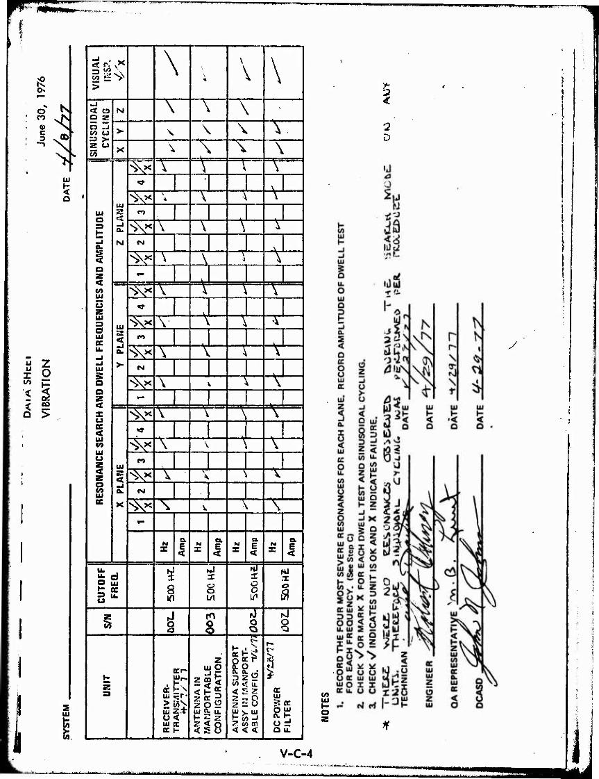
b. Vibration Tests. There were no resonances observed during the search made on any of the units tested. Therefore, sinusoidal cycling was performed per the procedure.
c. Visual Inspection. The visual Inspection showed that there was no damage Incurred to the units as a result of the vibration test.
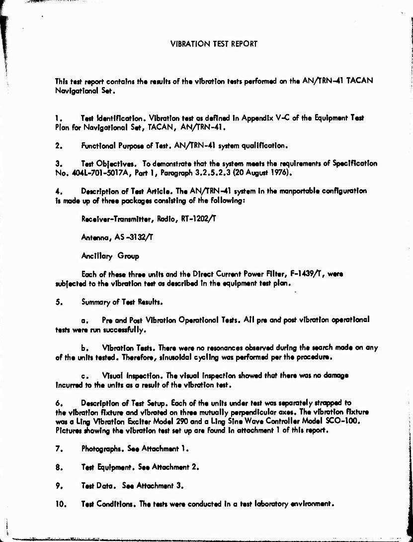
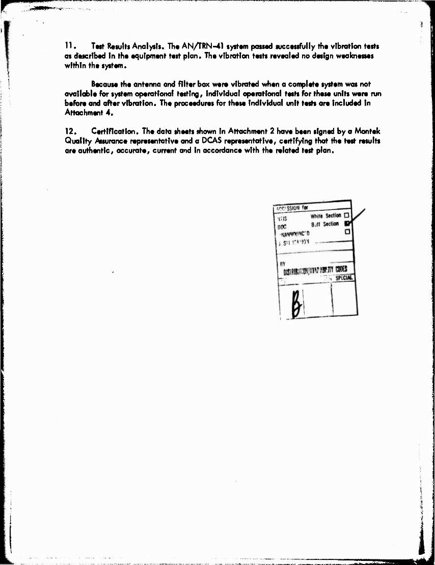
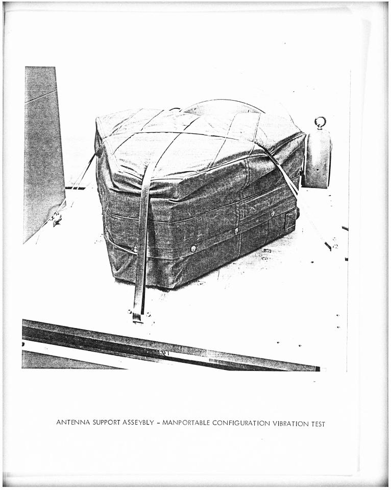
6. Description of Test Setup. Each of the units under test was separately strapped to the vibration fixture and vibrated on three mutually perpendicular axes. The vibration fixture was a Ling Vibration Exciter Model 290 and a Ling Sine Wave Controller Model SCO-100. Pictures showing the vibration test set up are found In attachment 1 of this report.
7. Photographs. See Attachment 1.
8. Test Equipment. See Attachment 2.
9. Test Data. See Attachment 3.
10. Test Conditions. The tests were conducted In a test laboratory environment.
-i,rJirniiiBi'lri[inn:jiiiriffl,-''Tiv rri YVTVU »JMämilitmm *mmmrtU'mmmmmmm»mimmi\mmmM*m»m ...**. ■,„.-,.-...-*.■■...,—i.- ........I1M^ ■j^hMfaij.n.m.,aaüB {auim „^...^.^„i-».... j „.. ..■■»-^^■■■■..■■.-^ M m .J.,ja-1A..._^^..-
** mmtm^mäm^tmmmmmmmtim
r py*^"-Ki:Htv>-T
11. Ttrt- Results Analysts. Th« AN/rRN-41 system passed successfully the vibration tests as disecrfbed In the equipment test plan. The vibration tests revealed no design weaknesses within the system.
Because the antenna and filter box were vibrated when a complete system was not available for system operational testing r individual operational tests for these units were run before and after vibration. The proceedures for these Individual unit tests are included In Attachment 4.
12. Certification. The data sheets shown in Attachment 2 have been signed by a Montek Quality Assurance representative and a DCAS representative, certifying that the test results are authentic, accurate/ current and In accordance with the related test plan.

r mm '"ii i
AHACHMENT 1
PICTURES
■■"■--- ->■■-- — tm - • ■■ " ■ -'- ^^■■>-^^.-—-■■■■"■^■^--^»'■^^i^
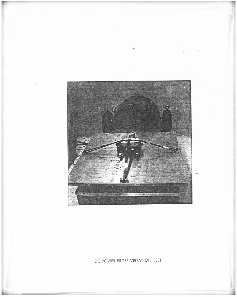
DC POWER FILTER VIBRATION TEST
K
ANTENNA SUPPORT ASSEYBLY - MANPORTABLE CONFIGURATION VIBRATION TEST
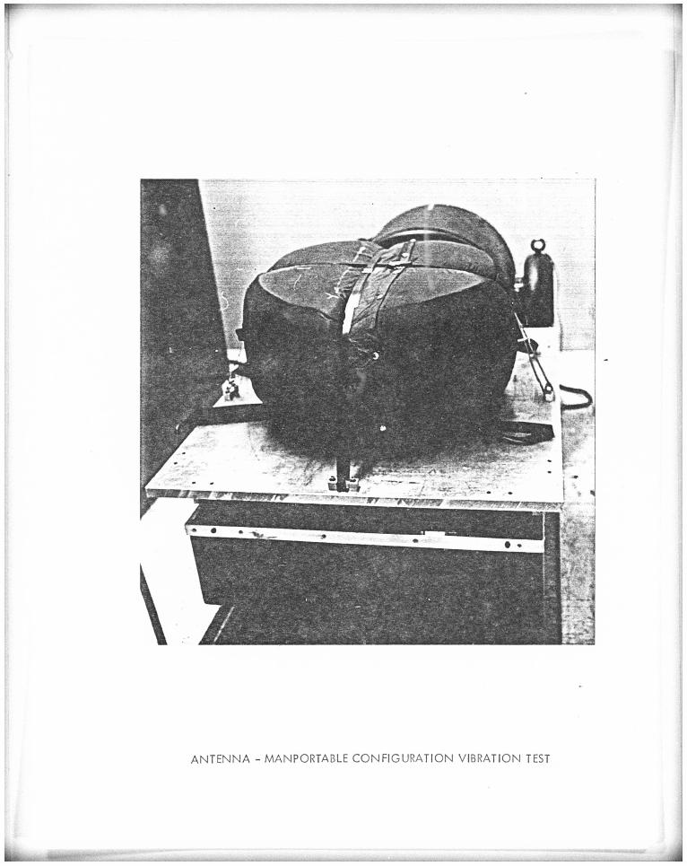
ANTENNA - MANPORTABLE CONFIGURATION VIBRATION TEST
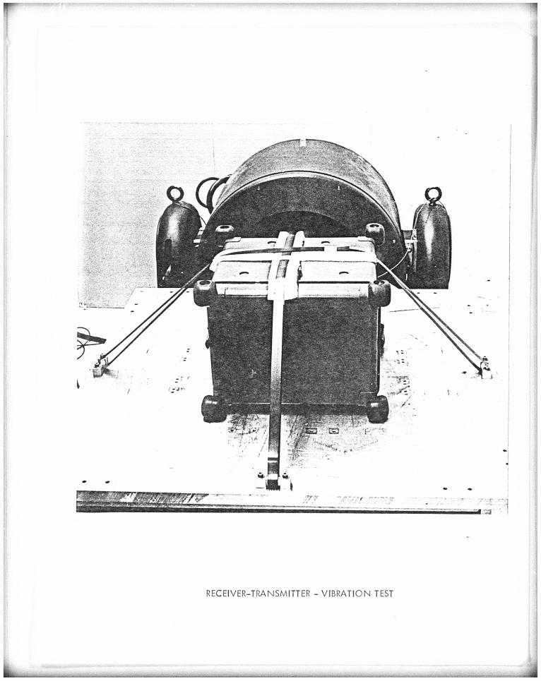
RECEIVER-TRANSMITTER - VIBRATION TEST

jumw.pi'Wiiwpw-
ATTACHMENT 2
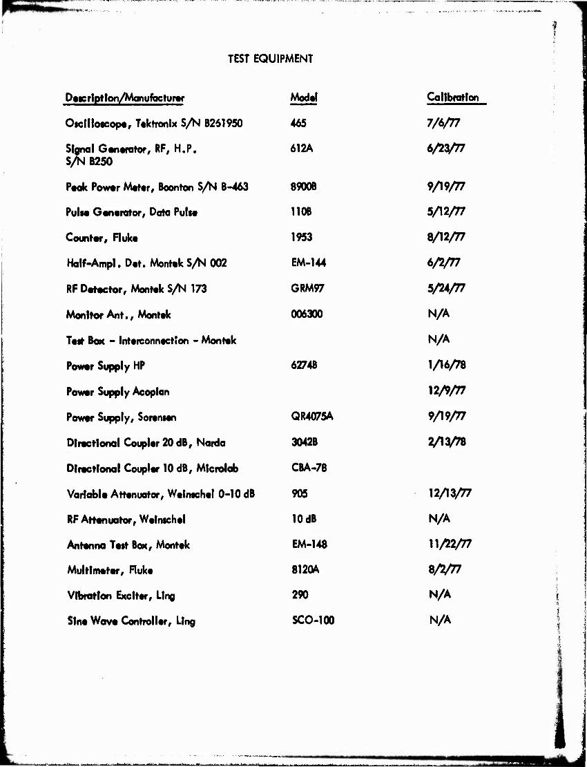
TEST EQUIPMENT
TEST EQUIPMENT
DticrlpHoo/Manufacturar Model Calibration
Oictllofcop«, Tektronix S/N B261950 465 7/6/77
Signal Ganerator, RF, H.P. S/0MB25O
612A b/22/n
P«ak Powvr M«ttr# Boonton S/N 1-463 89006 9/19/77
PUIM Genvrator, Data PUIM 110B 5/12/77
Counter, Ruk« 1953 8/12/77
Half-Ampl. D«t. Montok S^ 002 EM-144 6/2/77
RF Datoctor, Monttk S/N 173 GRM97 5/24/77
Monitor Ant. f Monttk 006300 N/A
Ttit BOK - IntoiconnoctSon - Montok N/A
Powor Supply HP 6274B 1/16/78
Powor Supply Acoptan 12/9/77
Powtr Supply, Soransan QR4075A 9/19/77
Dtractlonal Couplor 20 dB, Narda 3042B VV^8
Dlroctfonal Coupler 10 dB, Microlab CBA.78
Variable Attenuator, Welnachel 0-10 dB 905 12/13/77
RF Attenuator, Wetmchel 10 dB N/A
Antenna Test BOK, Monttk EM-148 11/22/77
Multimeter, Ruke 812QA Z/2/T7
Vibration Exclttr, Ling 290 N/A i ft
Slnt Wave Controller, Ling SCO-100 N/A
Lf^WW ihm ■ iirnirtili-rv Iti»- ii I ■■uriüiMiii
mmmmmmm w '<-^
AHACHMENT 3
VIBRATION TEST DATA SHEETS
i. —-»
nl
ON
CO
C -. ■ CO CJ
V UJ
o
u z u X 0 <s> »- ■< ^ < GO
O >
I
i s UJ
1 =a «>
> |\
4 A S
INU
SO
IDA
L C
YC
LIN
G
M \ \ \
> \ \ \ V X \ L\ \ \
PLI
TUD
E UJ
a.
N
v T \ <t •
V ' V 1 \ * V \ \
ro ■J ■>v A \ \ \ 1
«M \
1 Q <
1 o 1 UJ 1 u 1 «s 1 UJ a 1 UJ 1 oc 1 "* 1 «J 1 -J 1 UJ
1 0
1 x
1 cc < 1 UJ
1 M UJ u 1 z
1 z
° UJ cc
■V \\ \ —\—
^ \ |
.—»J
UJ 2
-J &.
>•
^V tV \ \ ^ «•
i
Svx iV V \ •^ CO
V \ V \ \
CM
V \ X \ \
UJ S < _J o.
X
v V \ \ \
<*
^ A \ \ \
n J ■\x ^ \ \ \ j CJ J ^ ^ \ \ V
<p"
N X
a. E <
H a. E <
N X
a. E X
o- 1 E <
CU
TOFF
FR
EQ
.
s in
Hi T
§ 1/1
O o
NJ 1 .1
ft
% i %
Nl
§
1 s
OCr-
UJ 2 + O < UJ C
AN
TE
NN
A I
N
MA
NP
OR
TA
BLE
C
ON
FIG
UR
AT
ION
.
AN
TE
NN
A S
UP
PO
RT
AS
SY I
N M
AN
PO
RT
- A
3 LE
CO
N F
1G.
T/fc
/7i
f~ 1 c- 1
OC i UJ \
Qu.
V) UJ
V-C-4
2 <
-2
y
^■--^ ■' --, H n miiihfirtiiii -nam i^ibäktmttmtäuuäiiätmm ^^^^-:^iilliiiiHiMtt.^ttM>u
HPIPnnrü JW^IIIII.J..JW,III.IW«I»3»WWW*«WIS^PW i wrw* ii w^menr^*
TEST DESCRIPTION \hA£*T,*n/ PATE tjh&Lll
OPERATIONAL TEST DATA SHEETS
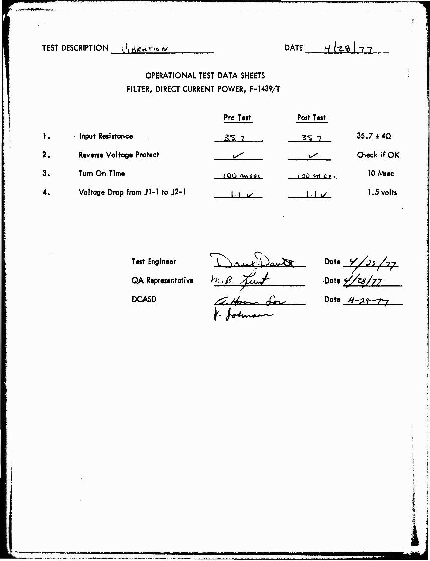
FILTER, DIRECT CURRENT POWER, F-1439A
Pre Test Post Test
1. Input Resistance
Reverse Voltage Protect
Turn On Time
Voltage Drop from Jl-1 to J2-1
3S i 3-3 1 35.7 ±4fi
2. ^ v^ Check if OK
3. IOÜ /V«AVl?t /0v> w we«.
11 •
10 Msec
4. I I 1/ 1.5 volts
CN Test Engineer I \^^^^t
QA Representative H>. ß .^tl^r
DCASD ^i/Wtrw. Q*^*-.
Date_^iy/2^
Dote <//*sh7
Date ^-3^-7^
«Ji»J<»a«i«M-i»i«>i««ii..>»«a»MlM»w>«M>»<M«Ml«|^^ HMMMHW - — . - ^^^-^-^J-i^ai^
ffPBPpgfgWI^WWi "! JPPWffPyy^W^^ffWP^ •mmmmmmrmmmmm^^m
DATA SHEET
ANTENNA OPERATIONAL TESTS
TEST O H^- <^a ANT SERIAL NO.: 2£2 %
DATE Y~ C 11
TECH Qr,^ T^^i^icl
I. Antenna Speed and Reference Triggers
Specification MEASUREMENTS
15 Hz 135 Hz 1350 Hz
PERIOD 66.666
±0.133 ms 7407 H$
±14.8 ps
BASE LINE LEVEL >+3.5V
740 H$ ±10 ps
PULSE AMPLITUDE ZZ.OV
PULSE RISE TIME ^20Ms
II. Antenna Speed Error
Antenna speed error alarm condition (3.5 Vdc min.)
Antenna speed error normal condition (0.7 Vdc max.)
III. Voltage Standing Wave Ratio (VSWR)
Z. 1.5:1 AS! /
IV. 15 Hz & 135 Hz Modulation (Check if OK)
'■A/r
H-L -77
\*l£:jät.v--\,*M,ivi i*M'& . ,......^..- -..,-.■-^ BteBM||BMflj|ii||(
mmm
DATA SHEET
ANTENNA OPERATIONAL TESTS
TEST f^t Uig ^a B&£ T^^^ ANT SERIAL NO.: ^g
DATE
TECH 7ÜZX-
I. Antenna Speed and Reference Triggers
Specification MEASUREMENTS
15 Hz 135 Hz 1350 Hz
PERIOD 66.666
±0.133 im 7407 ps
±14.8 ps 740 ps ±10 ps
BASE LINE LEVEL >+3.5V Sov^ y öLT S" o i/-
PULSE AMPLITUDE >3.0V ^".cv/ S'^ s:^"
PULSE RISE TIME *r 20Hs *- l/tS Li/AS L //*S
tenna Speed Error L^^lm-i •\t\iOMs -JMI'US II. An
Antenna speed error alarm condition (3.5 Vdc min.)
Antenna speed error normal condition (0.7 Vdc max.)
III. Voltage Standing Wave Ratio (VSWR)
j^l ^
^.1.5:1 I. S^ » |
IV. 15 Hz & 135 Hz Modulation (Check if OK) X
- - ■- ■■--■. -- - — - ■* —^ mm mmmlm——>-
™'^*'"SP'?!W'WW!'^W«^^pw**wi™"^ ■i ji.inu.MwwjMH.iUiit.i nyi
DATA Siller
C'i'UlATlONAL TCSTS
AN/riUI-41
System ^7 ScrX/6>. ^^1 -^
Dale i-'y-t?
Time ^/tx» '-^
V*iir&^_ha.Bl-.jkAl-^'„J&Z.^ Tecli ^ a.*~*
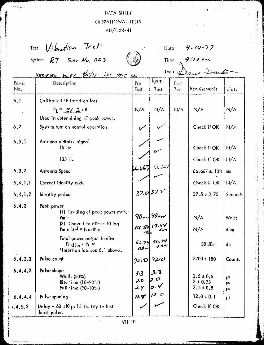
6.1
6.2
6.3.1
6.3.2
6.4.1.1
6.4.1.2
6.4.2
6.4.3.3
6.4.4.2
i
6.4.4.4
..4.5.2
\
Callbralccl RF iracrlion loss
Used in (Jeteriniiiing KF poal< pev/cr.
System turn on normal opciation
Aniennct racliatcd signal 15 lb-
135 IL
Antenna Speed
Correct identity code
identity period
Peol; power (1) Reading cf pcalc power mclcr Pm = (2) Conveit to d Dm - 10 log Pm x 103 = I'm dBm
Total power oulput in dDm
*lnserlion loss ice 6.1 above.
Pulse count
Pulse shape Widll» (50%) Rise lime (10-90^.) Fall time (90-10%)
Pulse spacing
Delay - 60 110 ps 15 Ik trig lc fiist hurst pulse.
N/A
3?.o*7*
90-
so,yf
POST
Tod
N/A
lOmuJ
19 f dm
73./0
33
13-o
VII-10
Post Tcsl Rcquirerncnls Units
N/A N/A N/A
Check if OK N/A
Check ff OK N/A
Check if OK N/A
66.667:!. 133 ms
Check If OK N/A
37.5:0.75 Seconds
N/A Waits
N/A dBm
50 dDm dB
7200:1.180 Counts
3.5:«: 0.5 2:t 0.25 2.5:i 0.5
ps ps
12.0J.0.1 PS
Check if OK
- - ■ ■ -■- ,, ,. ---" "- - -- fcM -- —'- ■■-- ■'"'■
lipill^P^IIIBPPWgywgPWP^w^ 'tWi'-gJWHII IIMIWWW.IIIJWLI...
No.
1 i
i i 1
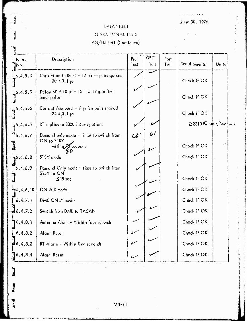
I 6.4.5,3
1 6.4.5,5
] 16.4.5.6
'6.4.6.5
6.4.6.7
k '•16.4.6.0
| 6.4.6.9
1 3; 16.4.6.10
I 6.4.7.1
-il6.4.7.2
1 16.4.8.
| 6.4.0.2
."6.4.8.3
^6.4.8.4
Dcscilptlun
l>ATA rvH!:i:i
or'.:?:/vriONAi.Trsrs
m/\WAA (Conlir.ucH)
Tcsi
3 3 1
Correct noilh ßursl •" V/ pulfi; polls spciccd 30 A 0.1 (iS
Delay m H 10 |js - 135 II-: Vii<i to first bursi \iv\i(i
Coned Aux h'j\:A - 6 f.»uls«2 paiii rnoccd 24:1.0.1 |iS
i
I'T replies to 3300 iiricrrc^aiioni
Demand only mode - times k> switch from ON io STDY y
witliitrJKf second;
ST5Y modo
Dornend Only mods " time to switch from STBY to ON
< 15 soc
ON All', mode
DM1: ONLY mode
Switch from DML to TACAN
Anlenna Alar;ii •• Within four seconds
Alarm Rcrct
RT Alarm - Within five seconds
Alarm Reset
y
^
^
IS'
Mr Vest
6/
l^
^
Post Tost
1 Juno 30, 1976
Rcquiromonls
Check il OK
Check If OK
Units
Check if OK
;>2310'C.;ui;:y''W.vJ)
Check if OK
Check if OK
Check f OK
Check f OK
Check f OK
Chock f OK
Check f OK
Check f OK
Check f OK
Check if OK
VII-11
■ -- .......^.-.;.fa......,..^ ..^■■■■u.,,.... ^-^^■■■-^».^■A^^..^.^-,. M^mfcaaia, .^^.i-:..., ^-...^.^-^■..^■■.: ....—,.^.^ J...L-,^....M.J ^.....^^.^......-.„....^.^..^^gj^^^g^^^^^jgig^i^
UP «.IM* müiinw.iwpijij -;1 J ( .WVWW'^W-'»^*^ fW""^ *>" J' ■ -HV* ijimijiWluiill!.. jjilu«j|piWP^n(m|R«<«P^M^pi!in9ff^^^^ ■POTCwsr-aff ü ws«
!
: f
■ i
AHACHMENT 4
PRE AND POST OPERATIONAL TEST PROCEDURES FOR ANTENNA AS-3132/r AND
FILTER, DIRECT CURRENT POWER, F-1439A
>■-■"■»■ VI rinllltf« ..i^--.,.^..-.»^.:.,.^— n »^WIMH^MMMBltaMai limmiämmmj^t
^mmrmwrnr*
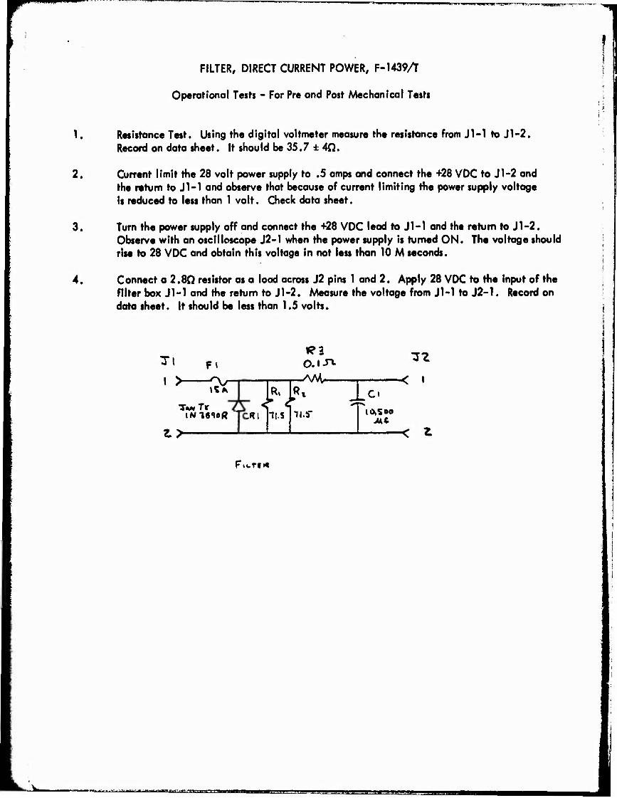
FILTER, DIRECT CURRENT POWER, F-1439A
Operational Tests - For Pre and Post Mechanical Tests
1. Resistance Test. Using the digital voltmeter measure the resistance from J1-1 to J1-2. Record on data sheet. It should be 35.7 ± 4Ci.
2. Current limit the 28 volt power supply to .5 amps and connect the +28 VDC to Jl-2 and the return to J1-1 and observe that because of current limiting the power supply voltage is reduced to less than 1 volt. Check data sheet.
3. Turn the power supply off and connect the +28 VDC lead to J1-1 and the return to Jl-2. Observe with an oscilloscope J2-1 when the power supply is turned ON. The voltage should rise to 28 VDC and obtain this voltage in not leu than 10 M seconds.
4. Connect a 2.80 resistor as a load across J2 pins 1 and 2. Apply 28 VDC to the input of the filter box J1-1 and the return to Jl-2. Measure the voltage from JM to J2-1. Record on data sheet. It should be less than 1.5 volts.
I >■
Fi
Ik TwTt
lNl«1oft TORI
Z>
k K
»?3 o.i-n. ./\M—
11-S ii.rr
< > .Ct
Mt < ^
FitTfi«
,„w '"• -■- '-"•"-"■"•'tllfllfllftf*«
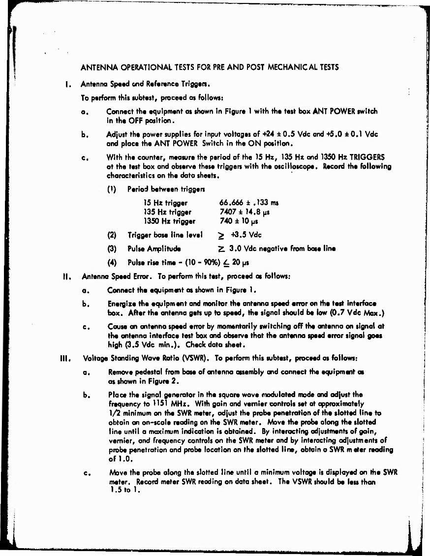
ANTENNA OPERATIONAL TESTS FOR PRE AND POST MECHANICAL TESTS
I. Ant«nna SpMd cmd Reference Trigg«n.
To perform this subtest, proceed as follows:
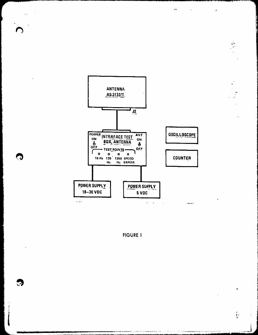
a. Connect the equipment as shown in Figure 1 with the test box ANT POWER switch in the OFF position.
b. Adjust the power supplies for input voltages of 4-24 ± 0.5 Vdc and +5.0 ± 0.1 Vdc and place the ANT POWER Switch in the ON position.
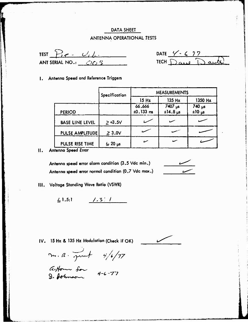
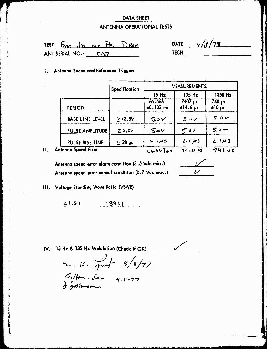
c. With the counter, measure the period of the 15 Hz, 135 Hz and 1350 Hz TRIGGERS at the test box and observe these triggers with the oscilloscope. Record the following characteristics on the data sheets.
(1) Period between triggers
15 Hz trigger 66.666 ± .133 ms 135 Hz trigger 7407 i 14.8 ps 1350 Hz trigger 740 ± 10 ps
(2) Trigger base line level ^ "^.5 Vdc
(3) Pulse Amplitude Z. 3.0 Vdc negative from base line
(4) Pulse rise time - (10 - 90%) I. 20 ps
II. Antenna Speed Error. To perform this test, proceed as follows:
a. Connect the equipment as shown in Figure 1.
b. Energize the equipment and monitor the antenna speed error on the test interface box. After the antenna gets up to speed, the signal should be low (0.7 Vdc Max.)
c. Cause an antenna speed error by momentarily switching off the antenna on signal at the antenna interface test box and observe that the antenna speed error signal goes high (3.5 Vdc min.). Check data sheet.
III. Voltage Standing Wave Ratio (VSWR). To perform this subtest, proceed as follows:
a. Remove pedestal from base of antenna assembly and connect the equipment as as shown in Figure 2.
b. Place the signal generator in the square wave modulated mode and adjust the frequency to 1151 MHz. With gain and vernier controls set at approximately 1/2 minimum on the SWR meter, adjust the probe penetration of the slotted line to obtain an on-scale reading on the SWR meter. Move the probe along the slotted line until a maximum indication is obtained. By interacting adjustments of gain, vernier, and frequency controls on the SWR meter and by interacting adjustments of probe penetration and probe location on the slotted line, obtain a SWR m eter reading of 1.0.
c. Move the probe along the slotted line until a minimum voltage is displayed on the SWR meter. Record meter SWR reading on data sheet. The VSWR should be less than 1.5 to 1.
•"•'-"" - ■ -" ^ ' v-r- -- -.-■--^»>-;-;,.y«.>.^^.a..„.,...J.M ...^ - ~iäm^m^^^^m \1
Wiumuij. iMP»iu»i.^ ^^M^^^^^I^Mil^ROVWB^^R^^Wmilllftlll I. lUii I PilJ.I lUPfl J I I
<5
ANTENNA AS-3132/T!
X
J2
^INTEMAQIIESir & BOX, ANTENNA
OFF , TESTPOINTS <> I 0 O O O
15 Hi 135 ' 1350 SPEED Hz Hi ERROR
(ft OFF
POWER SUPPLY
18-30 VDC POWER SUPPLY
5 VDC
OSCILLOSCOPE
COUNTER
»
FIGURE 1
t >
--...-.J-. i —"—t-****^-.**.******. Äj^i^^iij^B
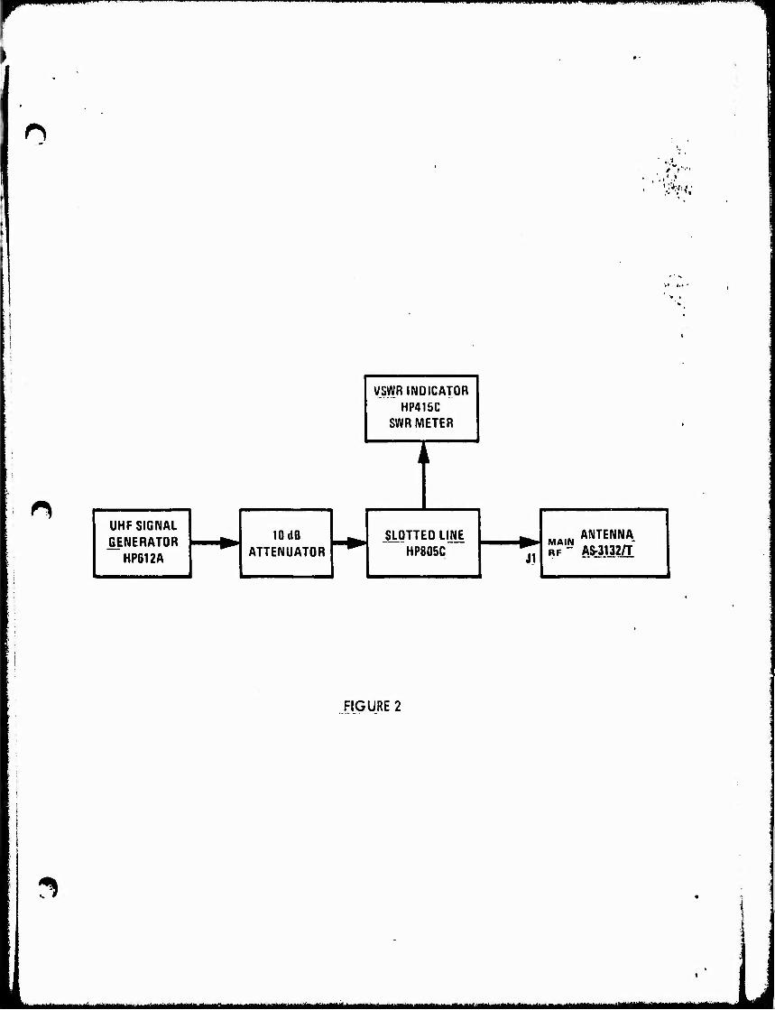
r mpp ■«^■■■■■■WiW^WPW^Pi^PBIIBiMWPIIPPl mrnammmBmrmmmmiBmmim mfmmi-'.m-ij■-',...mmmiiummf'
UHF SIGNAL GENERATOR
HP612A
10 dB ATTENUATOR
V/SVVR INDICATOR HP415C
SWR METER
JSLOTTED LI_NE HP805C J1
MA.M ANTENNA. R?^ AS-3132/T
D
FIGURE 2
mmummmMmaämtmiummuiimii&a ttt^^ttmumt^m^mm^t mm^ätMmmmilgttlUlmllU^ul^^

mmmmmm^mmmmmmammmmmmmmm
IV. 15 Hz and 135 Hz Modulation.
Use the antenna range and observe the modulation pattern when CW Is radiated through the antenna (f - 1213 MHz). Check the data sheet if the 15 and 135 Hz modulation pattern it correct.
iMMHiMiMHMUiiii
O • 9
1"HlS HEPORT HAS BEEN DELIMITS
<vN[ CLEARED FOR PUBLIC RELlAlf
UNDER DOD DIRECTIVE 5200.20 ANr
M' RESTRICTIONS ARE IMPOSED JPO!
|TS USE AND DISCLOSURE.
DISTRIBUTION STATEMENT A
APPROVED ^OP PUBLIC. »ELlASF
.P/5TMBUTI0N UNUHITEO.