unclassified ad 775 - defense technical information … · 269 775 final report ¢ design of model...
TRANSCRIPT

UNCLASSIFIED
AD 775
ARMED SERVICES TECHNICAL INFORMATION AGENCYARL~iGTlON HALL STATIONARLINGTON 12, VIRGINIA
UNCLASSIFIED

NOTICE: When government or other drawings, speci-fications or other data are used for any purposeother than in connection with a definitely relatedgovernment procurement operation, the U. S.Government thereby incurs no responsibility, nor anyobligation whatsoever; and the fact that the Govern-ment may have formulated, furnished, or in any waysupplied the said drawings, specifications, or otherdata is not to be regarded by implication or other-wise as in any manner licensing the holder or anyother person or corporation, or conveying any rightsor permission to manufacture, use or sell anypatented invention that may in any way be relatedthereto.
a

269 775
FINAL REPORT
¢ DESIGN OF MODEL OF A THERMOELECTRICq AIR CONDITIONING SYSTEM FOR SUBMARINES
E. W. FRANTTI
fI
JAN 18 1,%2
REPORT NO. 9161-01208-208 (1)
NEW PRODUCTS ENGINEERING DEPARTMENTW estinghouse Electric Corporation

FINIAL REPORTDESIQI OF MODEL, OF A THRIOIZCTRICAIR CONDITIONING SYSTIM FOR SUIMARINNS
Z. W. FRANTTIl
NEW PRODUCTS LABORATORIBSWISTINGIOUSE ELECTRIC CORPORATION
PITTSBURGH, PENNSTLVANIA
CONTRACT NO. NOSS 77095
CHIEF, BUREAU OF SHIPSDEPARtMKUT Of NAVY
WASHINGTOW 25, V. C.

FOREWORD
This report was the result of a contractinitiated by the Chief, Bureau of Ships, NavyDepartment, Washington 25, D.C. The originalresearch and development work upon which thereport is based was accomplished by the NewProducts Laboratories, Westinghouse ElectricCorporation of Pittsburgh, Pennsylvania, underBureau of Ships Contract No. NOBS 77095. Mr.A, F. Phillips of Code 431 was the ProjectOfficier. Mr. J. D. Meess of WestinghouseElectric Corporation was Supervisory Engineerin charge of work covered under the contract.Development started on 1 June 1959 and wascompleted on 1 May 1961.
Acknowledgement is made of the assistanceprovided by the personnel of Code 431 of theBureau of Ships. Acknowledgement is also madeof the invaluable assistance lent the authorby Mr. R. S. Lackey and Mr. R. Chamberlin ofWestinghouse Electric Corporation.
ii

ABSTRACT
A thermoelectric heating and coolingmodule has been constructed for installa-tion in a water to water air conditioningsystem aboard a submarine. This modulehas a cooling rating of 2550 BTU/hr. ata coefficient of performance of 0.75 andan operating current of 35 amperes de.This rating was based on a 85*F sinkwater temperature and a chill water temp-erature of 55*F. The unit was designedto withstand submergence pressures andthe corrosive effect of sea water in allwater passage@. It occupies a volume lft.by 1 foot by 3 inches and was designed forease in stacking into larger capacityunits without additional space beingrequired for coupling between units. Ithas a weight of 50 pounds.
Figure No. ae
33 Module 3 Variation of Heat Pumping Capacity vs. Chill Water Flow ...... 44
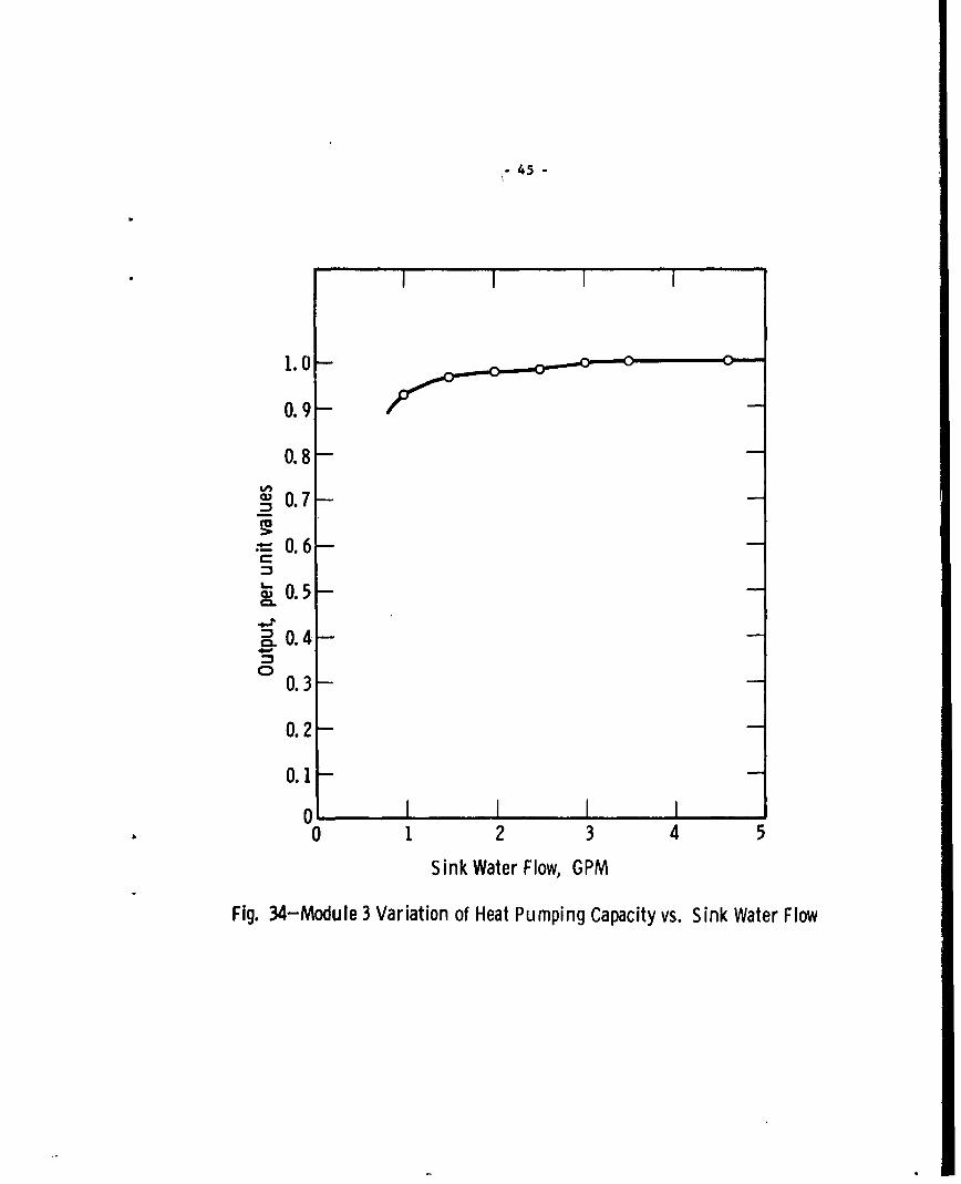
34 Module 3 Variation of Heat Pumping Capacity vs. Sink Water Flow ....... 45
35 Module 3 Variation of Strap Temperatures vs. Input Current..o..*.*.... 46
36 Module 3 Pressure Drop vs. Water Flow Thru Heat Exchangers............ 47
37 Module 3 Calculated Performance with Z of 2.6 for 1/2 Module .......*... 56
38 Module 3 Calculated Performance with Z of 2.95 for 1/2 Module..*...... 57
39 Freezer Heat Pumping vs. C.O.P. for Various Figure of Meis.....64
40 Freezer Heat Pumped vs. Input Current ................. o.o.......... 66
41 First Shock Test Setup.... ......... .. . . ........ .o .. . . ... . . .. .o . . ... s 69
42 Second Shock Test Setup. .. .. o..o .......... .... 0... .......... .... 71
43 Vibration Teat Fore & Aft Poa'sion ... so.............o..).....~........ 72
V

TABLE OF CONTENTS
Section Fa__ No.
I Introduction ....... ............. . .. ......... 1
11 Theory ...... ,..................1
III Module #1 Design ....................... 8
IV Module #2 Design ........ . .... , .... .... .14
V Module #3 Design ............ . ............ ........ ..... 22
VI Test Procedures ... .. 29
VII Test Results ..... . . . .................... 36
VIII Conclusions ............. ........ ,................. .. 39
Appendix I - Module Design Calculations .................. 51
Appendix II - Freezer Design Calculations ........ ......... 59
Appendix III - Shock Tests ..... o ......... ...... . 67
Appendix IV - Vibration Tests ,..........................70
vi

SUBMARINE THERMOELECTRIC AIR CONDITIONER
I. Introduction
The development of improved thermoelectric materials in recent years hasenhanced their acceptability in many applications where heat pumping is required.Because they are static devices, their application in submarine air conditioningis especially attractive. During some periods of operation of a submarine, it isessential that the sound level be at a minimum. Present systems are inherentlynoisy and as it is not desirable to discontinue air conditioning at any time, aneed has arisen for a quiet system of air conditioning. Thermoelectric heat pumpsappear to be ideal for this application. For this reason, the Navy had initiatedthis development as a step in a program to obtain shipboard systems and componentsutilizing thermoelectric materials. This development was intended to determineperformance characteristics of available thermoelectric materials, to evaluate andsolve problems relative to fabrication and heat transfer in a practical device, toevaluate practicality for submarine application, and determine in which areas majorefforts should be directed.
With these purposes in mind, the development was to lead to the designand construction of a model submarinie air conditioning and refrigeration system.This model was to utilize sea water as a heat sink and fresh water as the chilledmedium by which cooling was to be dispersed throughout the ship. In other words,this development was specifically directed toward the development of a water towater system in which heat is pumped from one water loop to another.
II. Theory
The basis of the thermoelectric effect is that conduction electrons indifferent materials have different average energy levels. In a semiconductor theelectrons in the conduction band have a higher average energy than the electronsin the conduction band of a metal. Thus, in the junction of a suitable semiconductorand a metal an electron current, due to an applied field, flowing from the metalto the semiconductor, will transfer thermal energy from the metal to the semicon-ductor. On the other end of the semiconductor where the eledtron flow leaves toenter a metal again the thermal energy will be released to the metal. This is agreatly simplified explanation of the thermoelectric or Peltier effect. There aremany other factors which influence the operation of a thermoelectric junction. Therate of heat pumped through the material per unit of current flowing is called thePeltier-coefficient, x.
Rate of heat flow, Q x r I
If a materials is heated on one end there will be an increase in the con-centration and velocity of electrons at the hot end, which will result in the diff-usion of electrons toward the cold end. The cold end then becomes negatively

- 2 -
charged with respect to the hot end. This potential difference caused by thedifference in temperatures between the ends of the material is called the Seebeckeffect. The Seebeck coefficient (a) or thermoelectric power of a material isdefined as the ratio of the potential difference to the temperature difference.
a 4-1
AT
The Peltier coefficient (x) is related to the Seebeck coefficient (a) by,
T
it d T
where T is the absolute temperature. In metals the value of a is Of the orderof microvolts per degree centigrade while in semiconductors, it is of the order ofmillivolts per degree centigrade.
So far, we have considered only the transfer of heat by electfon flow. A thermo-electric material of this type in which the major current car•riers are electronsis classed as an N-type material. Although a cooling system can be made using onlya metal such as copper and an N-type semiconductor, this would give very poorperformance as shown in Figure 1.
Insulated Boxr--
~Copper N-Type 1 Copper 44 -E lectron
Hot Junctio , I Cold Junction
FIGURE 1
If the cold Junction were enclosed in an insulated box, as is usuallydesirable, it can be seen that heat would leak into the box through the copper.There are, however, some materials which are classed as P-type materials in whichthe major current carriers are "holes". Basically, a hole is a vacancy in thevalence band of a semiconductor caused by an electron moving into the conductionband. These holes behave in the same way as free electrons possessing a positivecharge. These materials when heated at one end will develop an electric fieldopposite to that of the N-type material, and will transfer heat similarly to elec-trons but in the opposite direction. Thus, a practical heat pumping device orthermoelectric couple can now be constructed as in Figure 2.

-3-Cold Junction
Hot Junction-
Copper N-TyMtl J C
& l Insulated Box
ElectronFlow Cpe
FIGUR 2p--Cold JunctionFIGURE 2
There is now no heat leakage into the insulated box through the elect-rical current conductors, as both the positive and negative electrical connectionsare made on the hot junctions of the thermoelectric couple which are outside thebox. There is no theoretical necessity for the copper shown in the box connectingthe N and P type material together. The couple would perform as well if the Nand P type material were butted end to end. However, for practical purposes, theyare joined with a copper strap for convenience and to provide a relatively largesurface area through which the heat from within the box can enter the Junction.
Thus far, we have considered only the Peltier coefficient of thermo-electric material and.know that the heat pumping or cooling rate is proportionalto the electric current flowing through the material. Thus, the more currentthat is passed through the material, the more heat can be pumped. This is basic-ally true except that there are other major factors which enter in and limit theheat pumping rate. The first of these is the electrical resistance of any materialto current flow. This resistance to current flow produces the so called Jouleanheat or more conventionally the 12R loss in the material. As can be seen, thisheat is proportional to the square of the current and the resistivity of thematerial; However, since it is uniformly distributed throughout the material only 1/2of it is considered as opposing the Peltier heat flow- The second effect is thatcaused by heat conduction through the material itself from the hot Junction to thecold Junction. This heat leakage directly opposes the Peltier heat flow and isproportional to the temperature difference between the hot and cold Junction andthe thermal conductivity of the material. The rate of heat pumping of a thermo-electric material then can be expressed by the equation,
Q - I - /2 1p 1 L - KA (Th T)
where x - Peltier coefficient
-4-
I - Electric current
p - Resistivity of thermoelectric material
L - Length of thermoelectric material
A - Cross-section area of thermoelectric material
K - Thermal conductivity of thermoelectric material
Th - Temperature of hot junction
Tc. - Temperature of cold junction
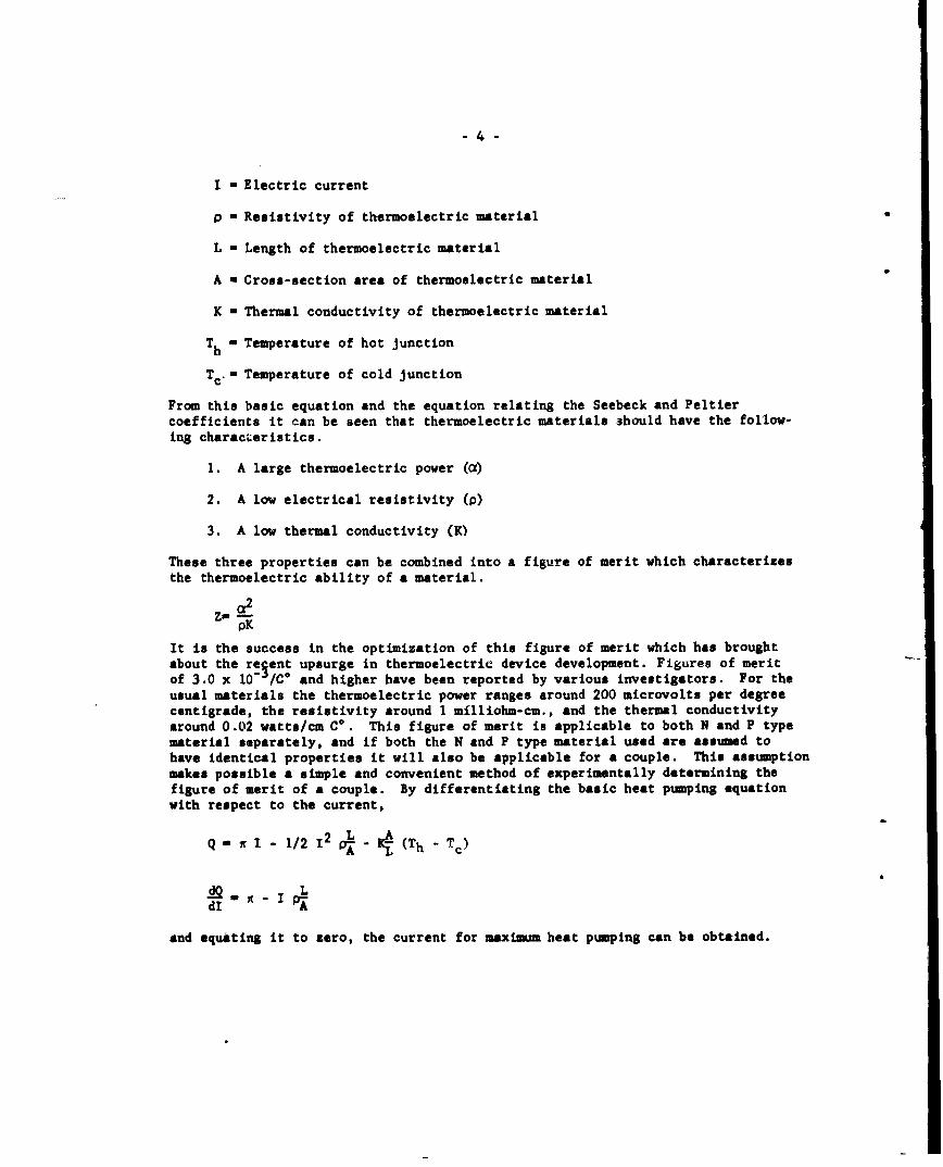
From this basic equation and the equation relating the Seebeck and Peltiercoefficients it can be seen that thermoelectric materials should have the follow-ing characLeristics.
1. A large thermoelectric power (a)
2. A low electrical resistivity (p)
3. A low thermal conductivity (K)
These three properties can be combined into a figure of merit which characterizesthe thermoelectric ability of a material.
pK
It is the success in the optimization of this figure of merit which has broughtabout the regent upsurge in thermoelectric device development. Figures of meritof 3.0 x 10" /C* and higher have been reported by various investigators. For theusual materials the thermoelectric power ranges around 200 microvolts per degreecentigrade, the resistivity around 1 mflliohm-cm., and the thermal conductivityaround 0.02 watts/cm C*. This figure of merit is applicable to both N and P typematerial separately, and if both the N and P type material used are assumed tohave identical properties it will also be applicable for a couple. This assumptionmakes possible a simple and convenient method of experimentally determining thefigure of merit of a couple. By differentiating the basic heat pumping equationwith respect to the current,
Q- I - 1/2 1' ' - K- (Th - T,)
L
dI e p
and equating it to zero, the current for maximum heat pumping can be obtained.

-5-
IQmaxu ApL
Substituting this current into the basic heat pumping equation and setting Q,the heat pumping rate, to zero the maximum temperature differential between thehot and cold junctions is found in terms of the material parameters.
(E)-6 (1 A)2 9 L- K A -.) - 1/2 _ A A -i•(Th'TC'
2A n2A Y, A0 - L 1/2 L (Th-Tc)
(Th-Tc) -1/2- i2A x L -1/2 1
p L L pK
Substituting for the Peltier coefficient its et.uivalent in terms of thermoelectricpower gives the fi.gure of merit in terms of temperatures which are easily measured.
Tca •d T - aTc
0f mC
2(1h.!.) . a2 . ZTc2 pK
A simple device as shown in Figure 3 can be made to determine the figureof merit based on this equation. The hot junctions are maintained at some specifictemperature while the cold junction is allowed to reach its lowest temperaturewith maximum Q current supplied under adiabatic conditions, that is, with no heatentering the cold junction.
- • Cold Junction
Max. W Copper , PT e Copper (-)Q CurrentsýT a, EXt.
. ............ Tempera ture ,
Measuring
Thermocouples
Th T
Insulation Filled Box
FIGURE 3
-6-
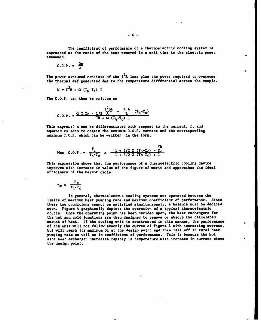
The coefficient of performance of a thermoelectric cooling system isexpressed as the ratio of the heat removed in a unit time to the electric powerconsumed.
C.O.P. - OcW
The power consumed consists of the I 2R loss plus the power required to overcomethe thermal emf generated due to the temperature differential across the couple.
W - 2 R+ a (Th-Tc) I
The C.O.P. can then be written as
j p, _ KA L (Th.Tc)C.o.p. - Z I Ta - 1/2 A L h"•R + X (Th-Tc) I
This exprebs .n can be differentiated with respect to the current, I, andequated to zero to obtain the maximum C.O.P. current and the correspondingmaximum C.O.P. which can be written in the form,
lh
Max. C.O.P. = - x 1 + 1/2 Z (Th-Te) - T&Th=Tc I + 1/2 Z (Th-Tc) + 1
This expression shows that the performance of a thermoelectric cooling deviceimproves with increase in value of the figure of merit and approaches the idealefficiency of the Carnot cycle.
TcT1c - Th.Tc
In general, thermoelectric cooling systems are operated between thelimits of maximum heat pumping rate and maximum coefficient of performance. Sincethese two conditions cannot be satisfied simultaneously, a balance must be decidedupon. Figure 4 graphically depicts the operation of a typical thermoelectriccouple. Once the operating point has been decided upon, the heat exchangers forthe hot and cold Junctions are then designed to remove or absorb the calculatedamount of heat. If the cooling unit is constructed in this manner, the performanceof the unit will not follow exactly the curves of Figure 4 with increasing current,but will reach its maximum Qc at the design point and then fall off in total heatpumping rate as well as in coefficient of performance. This is because the hotside heat exchanger increases rapidly in temperature with increase in current abovethe design point.

- 7-
Qc
+\
CL
E rCL
z~ C
CD °
4-.
SI
Current
Fig. 4 -Heat Pumping Characteristics of a Typical Thermoelectric Couple

-8 -
Typical construction of a thermoelectric couple is shown in Figure 5.
Heat Flow $b
Cold Plate
Copper N-Typ. P-Type ElectricallyStrap IE T/E Insulating &
IHati.1 I ati. IThermally Conducting Paste
Hot Plate
FIGURE 5
As many c.-cples are necessary to produce the required heat pumpingare connected in aeriew between the hot and cold plate. The electricallyinsulating but thermally conducting paste is a mixture of aluminum oxide andsilicon grease. It is used to prevent the couples from shorting one to theother and to provide good thermal contact to the hot and cold plates. The hotand cold plates which are of aluminum are also "hard-coated" to aid in the pre-vention of shorts. The couples are constructed by first soldering the elementsto the hot side copper straps and then fastening these straps, with elementsattached, to the hot plate. The copper straps which make up the cold Junctionsare then all soldered at one time to the elements in a jig, so that the cold junc-tion straps will all lie in one plane. The cold plate is then placed in thermalcontact with the cold junction straps and fastened to the hot plate to make amechanically rigid unit. This process can be reversed in that the copper strapscan be first fastened to the cold plate and the jig soldering accomplished on thehot junctions. Although in Figure 5, the cold and hot plates are shown simplyas plates, in the usual application they are heat exchangers which absorb heaton the cold side and dissipate heat on the hot side.
III. Module #1 Desin
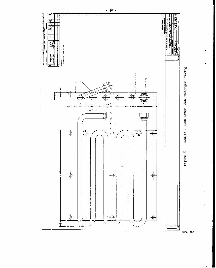
Consistent with the requirements as set forth by the Bureau of Ships,the decision was made to construct a small subsection or module several of whichtied together would supply the required 1 ton heat pumping capacity. This firstmodule was considered to be a prototype of the units to follow. Our approach tothe problem was to construct a sandwich type of unit in which one chill water heatexchanger would be sandwiched in between two sink water heat exchangers.
Separating the heat exchangers one from another would be the thermo-electric material which would be arranged to extract heat from the center or chillwater heat exchanger and dissipate it in the outer or sink water heat exchanger.The heat exchangers were constructed of coiled aluminum tubing brazed to a flat
-9-
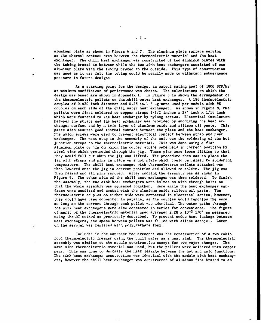
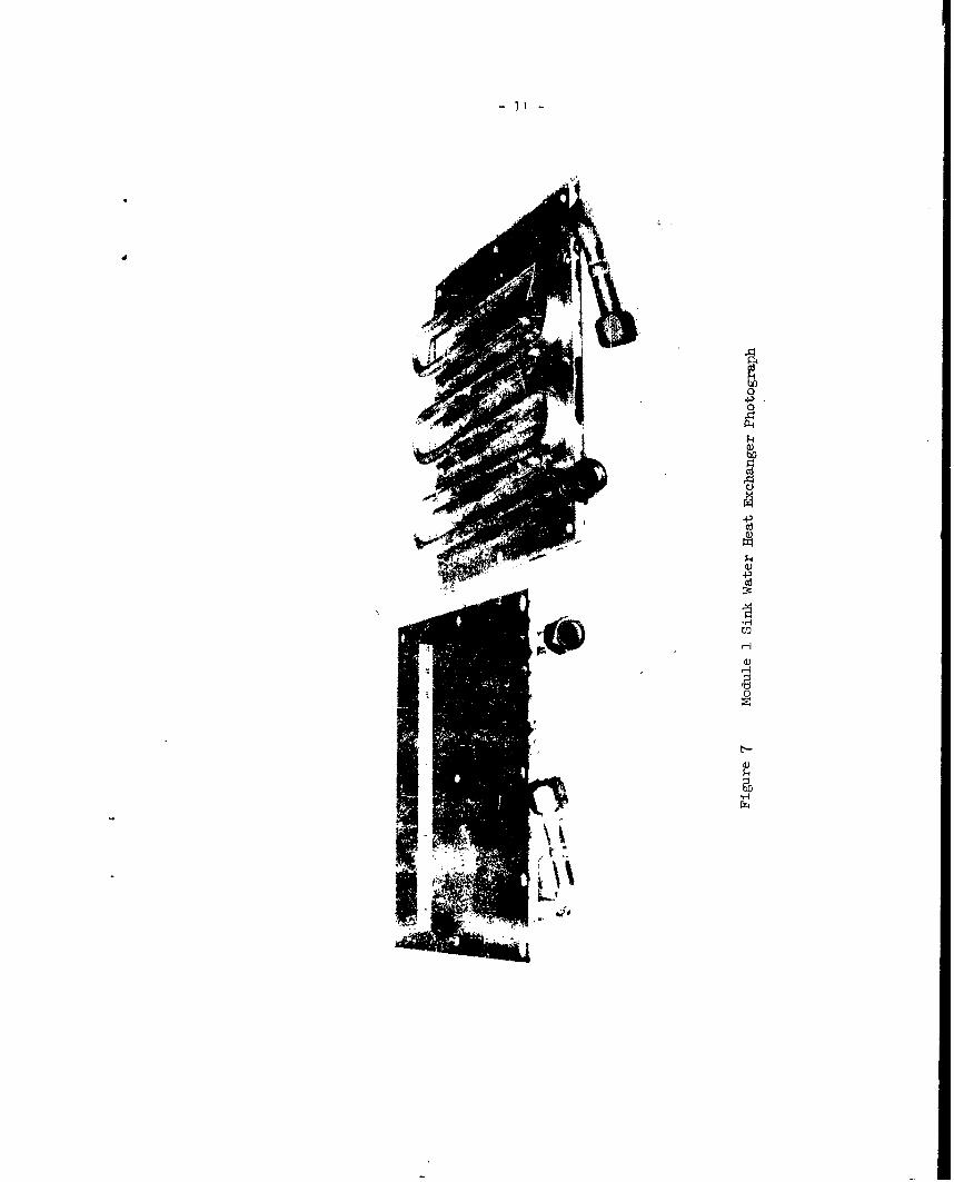
aluminum plate as shown in Figure 6 and 7. The aluminum plate surface servingas the thermal contact area between the thermoelectric material and the heatexchanger. The chill heat exchanger was constructed of two aluminum plates withthe tubing brazed in between while the two sink heat exchangers consisted of onealuminum plate with the tubing brazed to the outside. This type of constructionwas used as it was felt the tubing could be readily made to withstand submergencepressure in future designs.
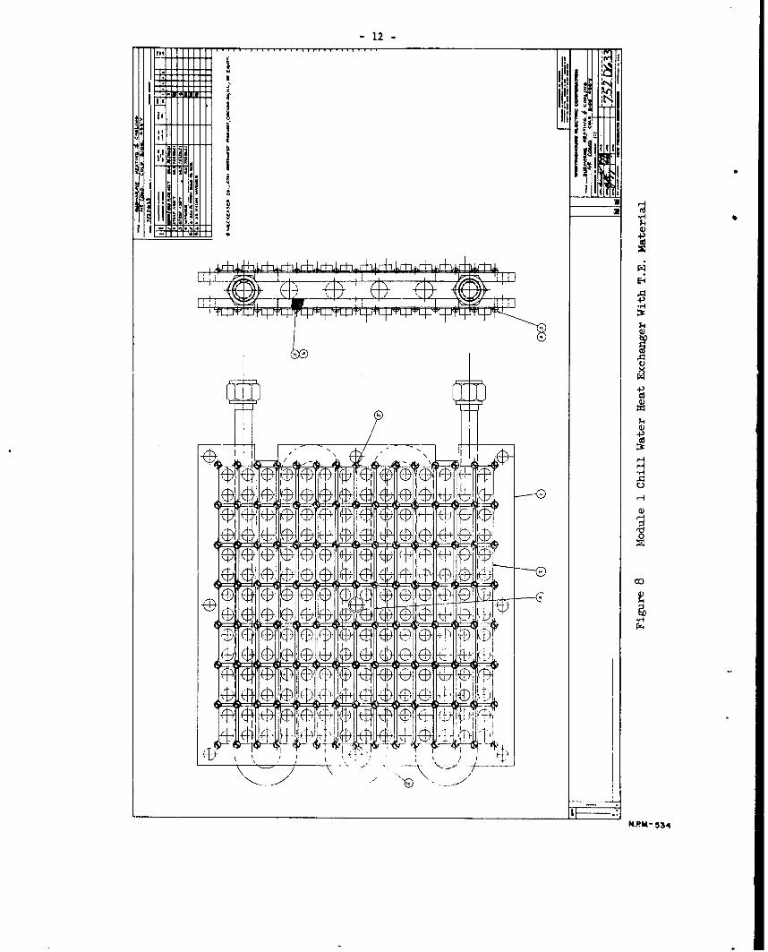
As a starting point for the design, an output rating goal of 1000 BTU/hrat maximum coefficient of performance was chosen. The calculations on which thedesign was based are shown in Appendix I. In Figure 8 is shown the arrangement ofthe thermoelectric pellets on the chill water heat exchanger. A 196 thermoelectriccouples of 0.420 inch diameter and 0.25 inr,.-, Yag were used per module with 98couples on each side of the chill water heat exchanger. As shown in Figure 8, thepellets were first soldered to copper straps 1-1/2 inches X 3/4 inch x 1/16 inchwhich were fastened to the heat exchanger by nylong screws. Electrical insulationbetween the straps and the heat exchanger was provided by anodizing the heat ex-changer surface and by . thin layer of aluminum oxide and silicon oil paste. Thispaste also assured good thermal contact between the plate and the heat exchanger.The nylon screws were used to prevent electrical contact between strap and heatexchanger. The next step in the assembly of the unit was the soldering of the hotjunction straps to the thermoelectric material. This was done using a flataluminum plate or jig on Thich the copper straps were held in correct position bysteel pins which protruded through the jig. These pins were loose fitting so thatthey would fall out when the jig was lifted. The procedure then was to place thejig with straps and pins in place on a hot plate which could be raised to solderingtemperature. The chill heat exchanger with thermoelectric pellets attached wasthen lowered onto the jig in correct position and allowed to solder. The jig wasthen raised and all pins removed. After cooling the assembly was as shown inFigure 9. The other side of the chill heat exchanger was then soldered. To finishthe assembly, the two sink heat exchangers were bolted on with through bolts sothat the whole assembly was squeezed together. Here again the heat exchanger sur-faces were anodized and coated with the aluminum oxide silicon oil paste. Thethermoelectric couples on either side were connected in electrical series, however,they could have been connected in parallel as the couples would function the sameas long as the current through each pellet was identical. The water paths throughthe sink heat exchangers were also connected in series for convenience. The figureof merit of the thermoelectric material used averaged 2.28 x 10⁻³ 1/C* as measuredusing the AT method as previously described. To prevent undue heat leakage betweenheat exchangers, the space between pellets was filled with silica aerojel. Lateron the aerojel was replaced with polyurethane foam.
Included in the contract requirements was the construction of a two cubicfoot thermoelectric freezer using the chill water as a heat sink. The thermoelectricassembly was similar to the module construction except for two major changes. Thesame size thermoelectric material was used, but the pellets were soldered unto copperpegs. This was done to dectease the heat leakage between the hot and cold junctions.The sink heat exchanger construction was identical with the module sink heat exchang-ers, however the chill heat exchanger was constructed of aluminum fins brazed to an
- 10 -
U"~~
!i•ii1
NI
T - 1
.iM,- 533
P-1
043.0
litO
-12-
I MKI
4.)
He4 H
14, 4
N.Rht- 534

11
U)
U,
U
4-,
�1)
a)4-,
HH
H
a)H
0
ON

- 14 -
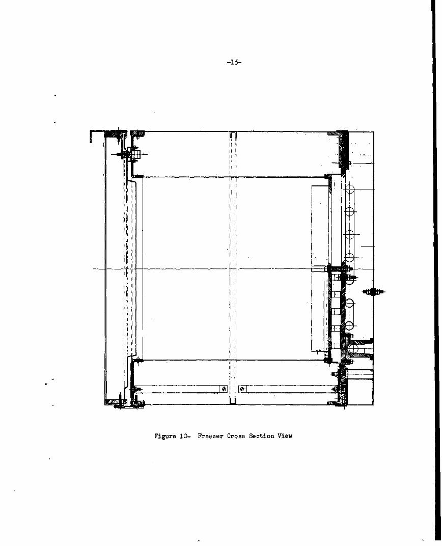
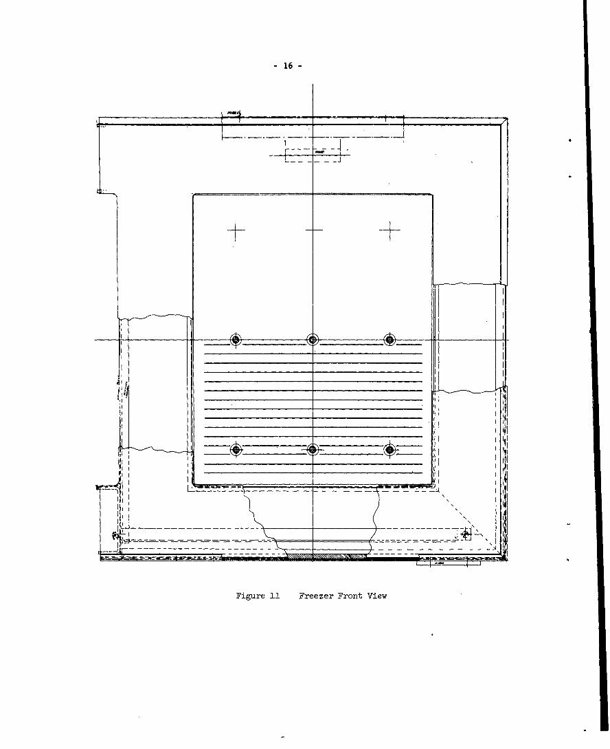
an aluminum plate. The details of the construction are shown in Figures 10,11, and 12. In addition to the fins, heat is extracted along the inside wallsof the box which are of aluminum and conducted to the cold plate which is inmetal to metal contact-with the inside walls. Polyureathane foam is used inthe walls of the box for insulation and strength. The area surrounding thethermoelectric pellets is also filled vith this foam. There are 50 couplesin the unit and the design calculations in Appendix II shown that the unitshould operate at 35 amperes and 4.0 volts with a coefficient of performanceof 0.32.
In order to demonstrate the cooling and heating capabilities of thethermoelectric module a demonstration aystem was constructed which consisted ofa chill water and a sink water loop. Each loop had a water to air heat ex-changer and a water pump. In operation with the module in the loops the airfrom one heat exchanger became warm and that from th' other cool, thus demon-,*ra"1 4- .•.e heating and cooling possible with ectrics. A picture ofthe xystem is shown in Figure 13.
IV. Module #2 Design
At the time of completion of the first module or prototype the programwas re-evaluated and its scope was changed. Instead of continuing with the con-struction of a 1 ton unit it was decided that one more module would be madewith emphasis on reducing size and weight and improved performance. The scopewas further extended to include the construction of a third module which was toinclude a sprayed on copper strap technique which was under development at thetime. This third module was also to be a prototype of a shipboard unit.
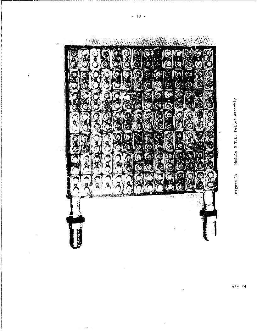
The same number and size of thermoelectric pellets was used in thesecond module. It differs mainly in that the tubing coils on the heat exchangerswas increased in length and flattened slightly to increase the contact area tothe aluminum plates to which they were brazed. This can be seen by comparingFigure 6 and Figure 15. The plates themselves were also made thinner. This ineffect was an attempt to improve the performance of the heat exchangers so thatthere would be less temperature differential between the junction straps and thewater. Stainless steel screws with insulating shoulder washers were used tohold the junction straps to the chill heat exchanger instead of nylon screws asthey could be fastened tighter. This is shown in Figure 14. A polyureathanefoam was used around the thermoelectric material as it had been found that thesilica aerojel had a tendency to dry out the aluminum oxide paste beneath thejunction straps. Thermoelectric material with an average figure o• merit of 2.41x 10⁻³ 1/C' was used which was somewhat higher than the 2.28 x 10-51/C* of thefirst module. In addition to making the heat exchangers lighter, a reduction inweight and size, was also obtained bringing the water connections from each heatexchanger to the outside of the unit. This can be seen in Figures 15 and 16which shows the completely assembled module.
-15-
I III
I Ij II
Il II II
II lI
Iii I
,,i I
IIi i
I Ii I
IrIi
I I
IIII t
II J
Figure 10- Freezer Cross Section View
- 16 -
14
______________________ ______________________ II________________________________________ _________________________________________ II
III
- I
� -. - 2�4
NN
-\ ii--- 'I
Figure II Freezer Front View

171
RP 149 1
l~t ~E-1
C)j
P4.
uHP

-20-
0)
r,0
410
RP- 4
AIR

- 22 -
V. Module #3 Design
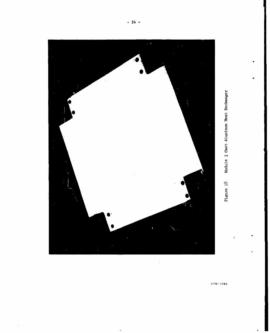
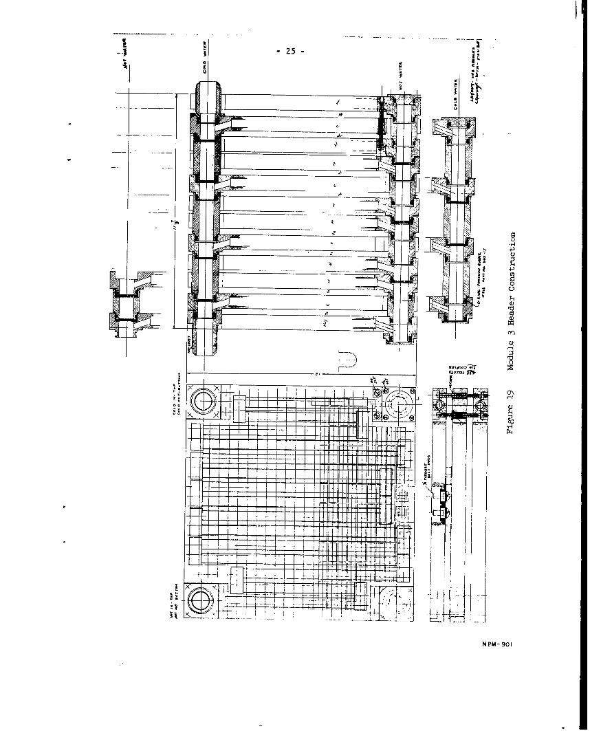
This unit which was to be a shipboard design was quite different fromthe previous units. The experience gained on the previous modules indicated thatheat exchangers which could remove the heat with very little temperature differ-ential would greatly increase the performance. To this end the heat exchangerswere then constructed by casting aluminum around a coiled tube. The aluminumaround the tubing providing a good thermal conducting path and also a flat sur-face on which the thermoelectric couples could be assembled. Further improvementin the heat exchangers was obtained by increasing the length of tubing. Thiswas done by obtaining very small radius 180* end bends which were brazed on asshown in Figure 17. The increase in length of tubing however was gained at theexpense of pressure drop of the water through the tubing. It was felt th, improve-ment in performance would outweigh the loss introduced by the increased pressuredrop. The cast in aluminum heat exchangers are shown in Figure 18. The waterinlet and outlets or headers were constructed so that no external water crossconnections are required in the module or between other modules of the samedesign. This was accomplised as shown in Figure 19 by the use of "0" ring sealedconnections between headers. In addition, this design permitted the water flowto be arranged in either series or parallel flow or various combinations of flowthrough both chill and sink heat exchangers when more than one module was used.This type of construction made the external outline of a module to be simple abox, 1 foot by 1 foot by 3 inches and the stacking of several modules togethercould be done in the minimum of space. All of the heat exchanger tubing andheaders were constructed of 10-90 cupro-nickel for good salt water corrosionresistance and all tubes were of sufficient strength to withstand submergencepressures. Efficient heat exchangers were required for two reasons, to improveperformance of the thermoelectric material, and to remove the additional heatintroduced by the increase in the packing factor gained by the use of the sprayedon junction strap technique. With an increase in the number of couples per squareinch more heat must also be removed per square inch.
The increased packing factor of thermoelectric material was obtainedby the spraying the hot junction straps onto the sink he&t exchanger. Thistechnique allows closer packing as no additional fastening devices are requiredto hold the strap in place, and as better thermal conduction to the heat exchangeris obtained by intimate contact between the strap and heat exchanger. To obtainelectrical insulation, a 5 mil thickness of aluminum oxide is first sprayed on theflat surface of the heat exchanger. Using a grid or matrix of stainless steelwhich outlines the straps, a layer of aluminum is sprayed on for good adheranceto the oxide. Then, a layer of copper is sprayed on to the required thickness.For this module enough metal was sprayed on so 4that the thickness of the strapafter being fly cut to a smooth surface was 0.040 inches. In Figure 20, is showna heat exchanger after being sprayed and in Figure 21 after it has been machined.Before machining a layer of epoxy resin is Ifainted over the complete sprayed surface.This was done to prevent the soldering flux which was used to tin the straps fromsoaking into the aluminum oxide and nullifying its electrical insulating properties.The thermoelectric couples were Poldered to the straps with the aid of a stiffcardboard matrix shown in Figurt. 22. This matrix was positioned over the strap

40r
'A-. ro Io
-24-
co
c-fl
N PM - 1496
-25-
00
X J
T' _
;~~l ;>J j I Iý!H +-3
L __1'I
N M 01

-26-
Als to
'cu
It 4A
4,14
eko
P43
4?*1-41

-27-
41,
rd
N M 49

-28-
.7/
4-)
0
(Y)
N PM- 1357

- 29 -
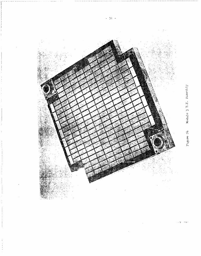
area and the pellets were inserted into the holes one by one in correct sequence.A layer of foam rubber was then placed over the exposed couples and weights wereapplied over the rubber to gently but firmly force the pellets into intimate con-tact with the junction straps when the heat exchanger was raised to solderingtemperature. After cooling, the matrix was removed by soaking in warm water.Figure 23 shows the pellets soldered to the heat exchanger. The cold junctionstraps were soldered in place using the same method as described previously forsoldering the hot junction straps of module 1 and 2. In Figure 24 is shown aheat exchanger with thermoelectric assembly completed. The chill heat exchangerwas sprayed with a 5 mil aluminum oxide coating on both sides for electrical in-sulation. A silicone grease was also applied to the surface for good thermalcontact. As in the previous units the chill heat exchanger was sandwiched inbetween the two sink heat exchangers and held together by two 1/4-20 high strengthbolts in each corner as shown in Figure 25. The bolts went through the chill heatexchanger and are thermally insulated from it by "Micartal*spacers. The couplingbetween the two sink heat exchangers was made such that the water flow was inseries, although parallel flow could as easily have been obtained. Figure 26 showsthe completed module,
VI. Test Procedure
Testing of both modules No. 1 and 2 was accomplished in the same manner.Warm water from the plant supply was circulated through the sink or hot side heatexchangers. After passing through the module, the water was dumped in the plantdrain. The cold water for the chill or cold side heat exchanger was also obtainedfrom the plant supply. Here again, the water was thrown away after passing throughthe module. The heat pumping capacity of the module was determined by measuringthe temperature differential between the incoming and outgoing chill water, Forthe heat pumping capabilities of the modules this temperature differential wasrelatively small and of the order of one half to two degrees Fahrenheit. To mea-sure this difference accurately, two differential thermometers were used, one inthe inlet line and one in the outlet line. These thermometers were graduated toread to O.010C and could be estimated to the third decimal point, Before startingthe test the two thermometers were calibrated together in a common water bath ofapproximately the temperature of the chill water. Their difference in readingswas recorded and was used as a correction factor in obtaining the true temperaturedifferential. After calibration, the thermometers were placed in wells in the pipingas close to the inlet and outlet of the module as wasphysically possible. The testwas then run by maintaining a constant flow and temperature of the incoming sinkand chill water and measuring the temperature differential obtained with variousvalues of input current to the module. The heat pumping capability was then deter-mined in BTU/hr as the temperature differential in degrees Fahrenheit times thewater flow in lbs per hour,
Q - LAT x Flow Rate
In this manner, a curve was obtained showing heat pumping rate versuscurrent input to the module. The coefficient of performance at each current wasreadily obtained by measuring the voltage input to the module. The coefficient of
* Micarta reg g trade name

-30-
43
p43
(1
enit C0)
N PM - 13
-- -- --r --- - -- -- - - -- -- -- -- -- -- -- - -- -- -- -- - -- -- -- -- -- -- - -- -- -
Alll
'00
r7'
po :p'

-NO
- --- C-_

11MI
" 34 "
performance then becomes,
c.o.P Output QBTU/hr.Input V x I x 3.413 BTU/hr/wa&t
This was basically a simple test and could quickly and satisfactorily deter-mine the performance of a module. However, several difficulties were encounteredwhich increased the complexity of the tests. Operating off the plant water supplyline, a constant flow and temperature was not obtainable. This was overcome tosome extent by making repeated readings at each value of current. Thus, the errorswould tend to average out although the time consumed per test was greatly increased.To decrease the time response of the differential thermometers their bulbs wereinserted directly in the water flow through rubber packing seals. In the testingof the first two modules this introduced no errors as the pressures involved werevery low. As the thermometer bulbs were pressure sensitive this was not satisfactoryfor testing the third module where the pressure drop across the module was consider-ably greater.
In testing the this module, the system was changed somewhat. Figure 27shows the test loops. Both the chill and sink water systems were made closed loopsso that their temperature and flow could be controlled more readily. The temperaturedifferential between the entering and leaving chill water was measured in two dif-ferent ways. Improved thermometer wells were constructed which provided a largecontact area between the chill water and the well. The thermometers sat in the wellsunder atmospheric pressure and were thus not affected by the pressure in the chillwater loop. A small amount of water was placed in the wells to provide good thermalcontact between the thermometer and the well. Thermocouples were also inserteddirectly into the inlet and outlet water flow through glass insulated bushings sol-dered directly in the inlet and outlet fittings. An insulating enamel was sprayedover the thermocouples exposed within the fitting to prevent leakage currents throughthe water from one thermocouple to the other. The thermocouples as shown in Figure 27were connected differentially so that their output was a direct measure of the temp-erature differential between inlet and outlet water. For the range of temperaturedifferentials obtained the thermocouple output was around 100 microvolts and below.This output was measured by a precision Rubicon Bridge and galvanometer. With theaid of the appropriate thermocouple tables, the reading of the bridge was convertedto degrees of temperature. A very good agreement between the thermocouples and thedifferential thermometers was obtained especially at the higher heat pumping rates.Thermocouples were also inserted in the sink loop to determine the amount of heatbeing dissipated in the sink water. Knowing the input, output, and heat dissipated,a heat balance was obtained which was a good control over the accuracy of the measure-ments.
Pressure gauges were inserted in the ingoing and outgoing lines to determinethe pressure drop through the module at various flows. Flow rates were measuredby rotameters inserted in the outgoing lines. Although the flowmeters were of + 2

-35-
U,.

- 36 -
per cent accuracy they were calibrated by weighing a timed flow to an accuracy of+ 1/2 per cent. Measurement of the sink and chill water temperatures were madewith thermometers with an accuracy better than + 1/2 per cent. Voltage and currentwere also measured using instruments of + 1/2 per cent accuracy.
As shown in Figure 27, the temperature of the chill water was maiitainedconstant at the desired value by adding heat electrically to the water in the chillwater reservoir. This control was maintained automatically within a 0.10F by anelectronic temperature controller which turned a portion of the heat on and off asrequired. The sink water heat exchanger was held constant by a water to waterheat exchanger which extracted heat from the sink water loop. The plant water supplywas used as the cooling water and its flow was controlled both manually and auto-matically to maintain the desired sink water temperature.
Pressure testing of the heat exchangers separately and of the completedthird module was done statically up to 2000 psi. No noticeable effect was observedfrom these tests.
Shock and vibration tests were conducted on the third module to MIL-S-901Band MIL-STD-167. Two completeishock tests were made. The first one was run withthe same water running through both the chill and sink heat exchangers. The unitwas energized at 35 amperes. The second test was run with approximately 85°F water
,running through the sink heat exchanger and 50*F water through the chill heatexchanger. The unit was again energized at 35 amperes. The vibration test was runwith the same temperature water running through both the sink and chill heat ex-changers and with an input of 35 amperes. The vibration machine used was not capableof oscillating in the vertical plane so this portion of the test was simulated bymounting the module at 900 to the vibrating table. The results of the tests areincluded in the appendix.
VII. Test Results
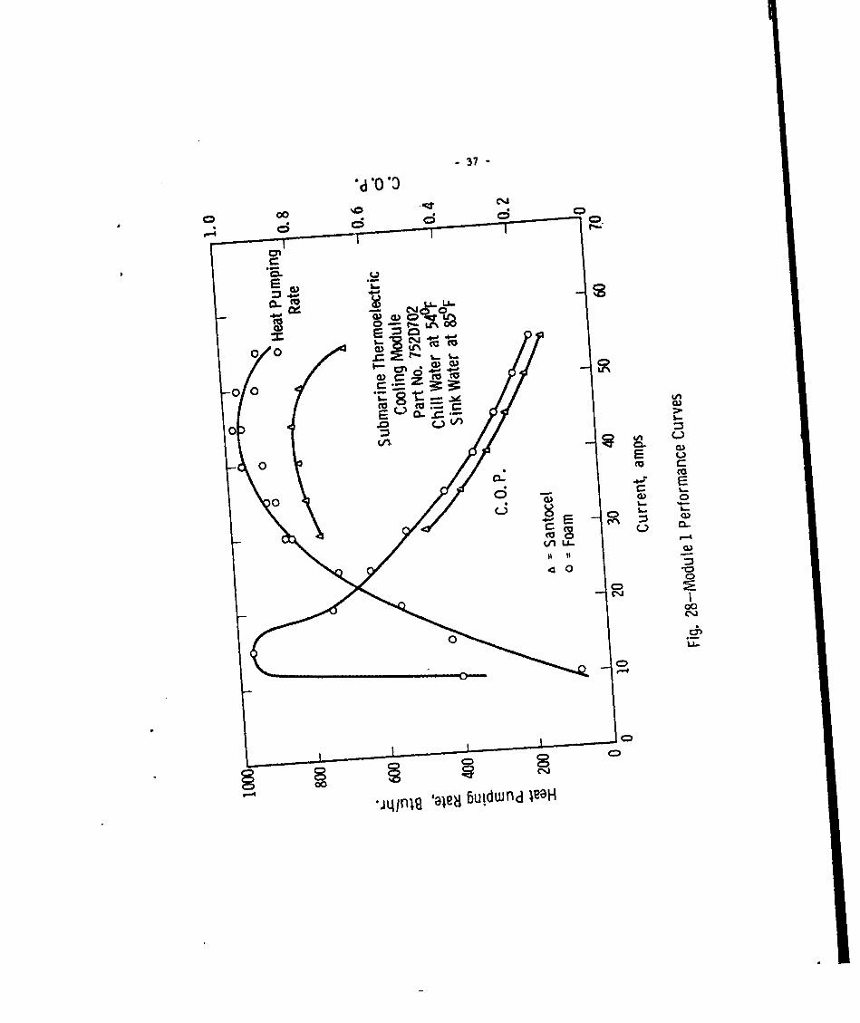
In Figure 28 is shown the typical performance curves obtained for the firstmodule. Disassembly of this unit showed that the silica aerogel used for thermalinsulation around the thermoelectric pellets had a tendency to dry out the siliconpaste used underneath the junction straps. The silica aerogel was replaced withpolyurethane foam and this improved the performance as shown in the figure. Forthese tests the flow rates for the chill and sink water was 38 lb/min and 35 lb/minrespectively. A shock test and vibration test was also made on this module undernon-operating conditions. Although several junctions broke during these tests,there was no damage to the thermoelectric material itself. The break in the junctionwas between the plating and the pellet and we believe was caused mainly by the loosen-ing of the bolts holding the unit together during the tests.
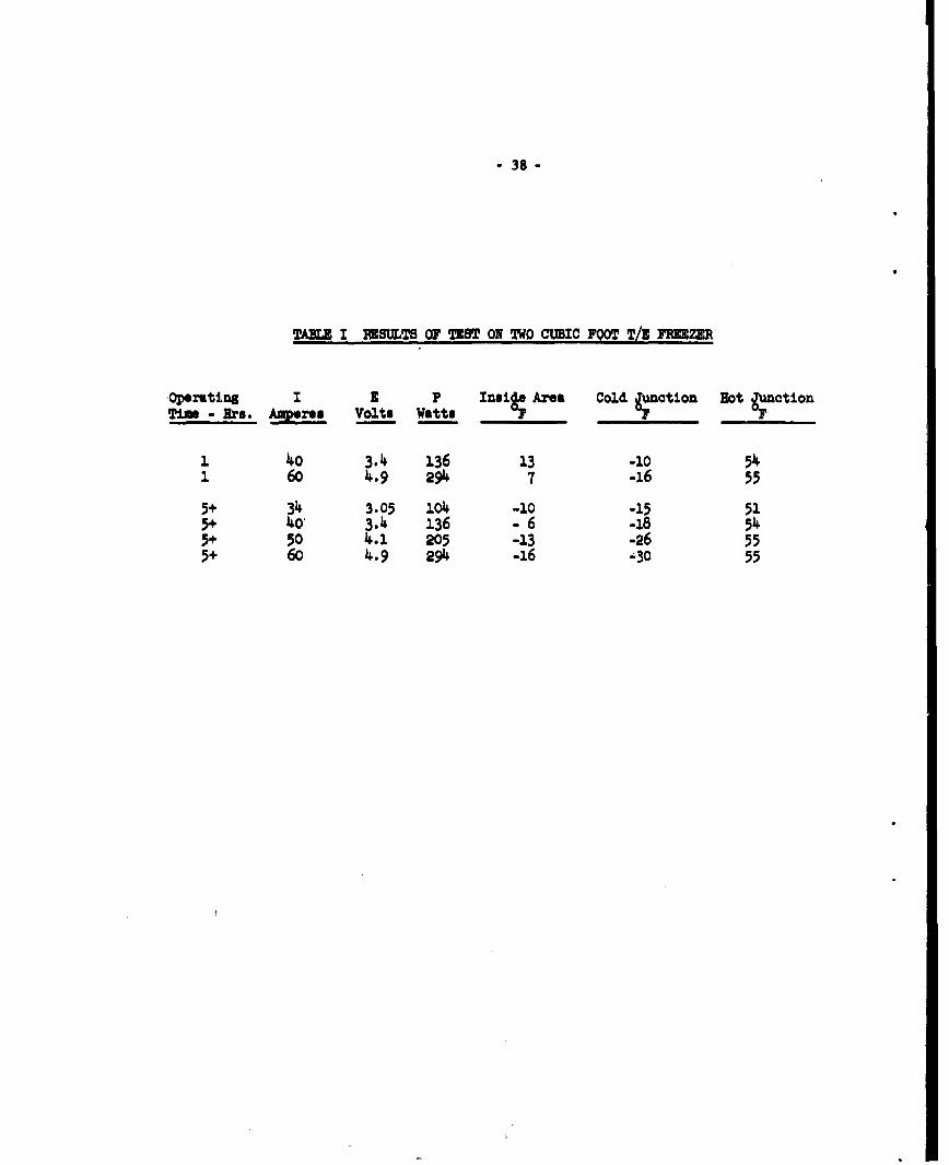
The temperatures shown in Table I are those reached after the operating timesindicated. The inside area temperature is the temperature of the air in the centerof the box. The lower limit of -30OF represents the lowest temperature reached atthis location in an operating device.
-37-
000
* .W-
0 0
00 0
0 0o
-EE
00
00cW.-
J~
0) U--
0 "00
00
*In~ '~e~j iudwfd I12*1
- 38-
TAZ I RNSULTS OF TEST ON TWO CUBIC FOOT T/ FMzER
Opr•ting 1 3 P Ins.i Area Cold Junction Hot JunctionTim - Ire. .wpres Volts Watt. .....
So40 3.4 136 13 -10 541 60 4.9 294 7 -16 55
5+ 34 3.05 11•4 -10 -15 513+ 40o 3.14 136 - 6 -18 5145+ 50 4.1 205 -13 -26 555+ 60 4.9 294 -16 -30. 55
I
-39 -
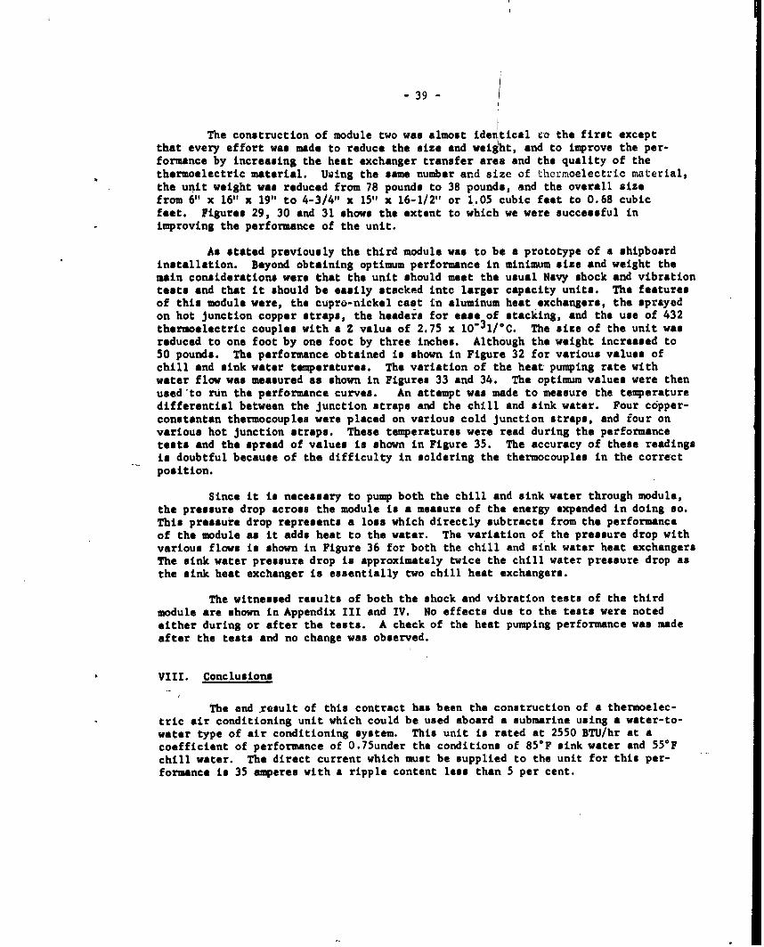
The construction of module two was almost ideritical ro the first exceptthat every effort was made to reduce the size and weight, and to improve the per-formance by increasing the heat exchanger transfer area and the quality of thethermoelectric material. UWing the same number and size of thermoelectric material,the unit weight was reduced from 78 pounds to 38 pounds, and the overall sizefrom 6" x 16" x 19" to 4-3/4" x 15" x 16-1/2" or 1.05 cubic feet to 0.68 cubicfeet. Figures 29, 30 and 31 shows the extent to which we were successful inimproving the performance of the unit.
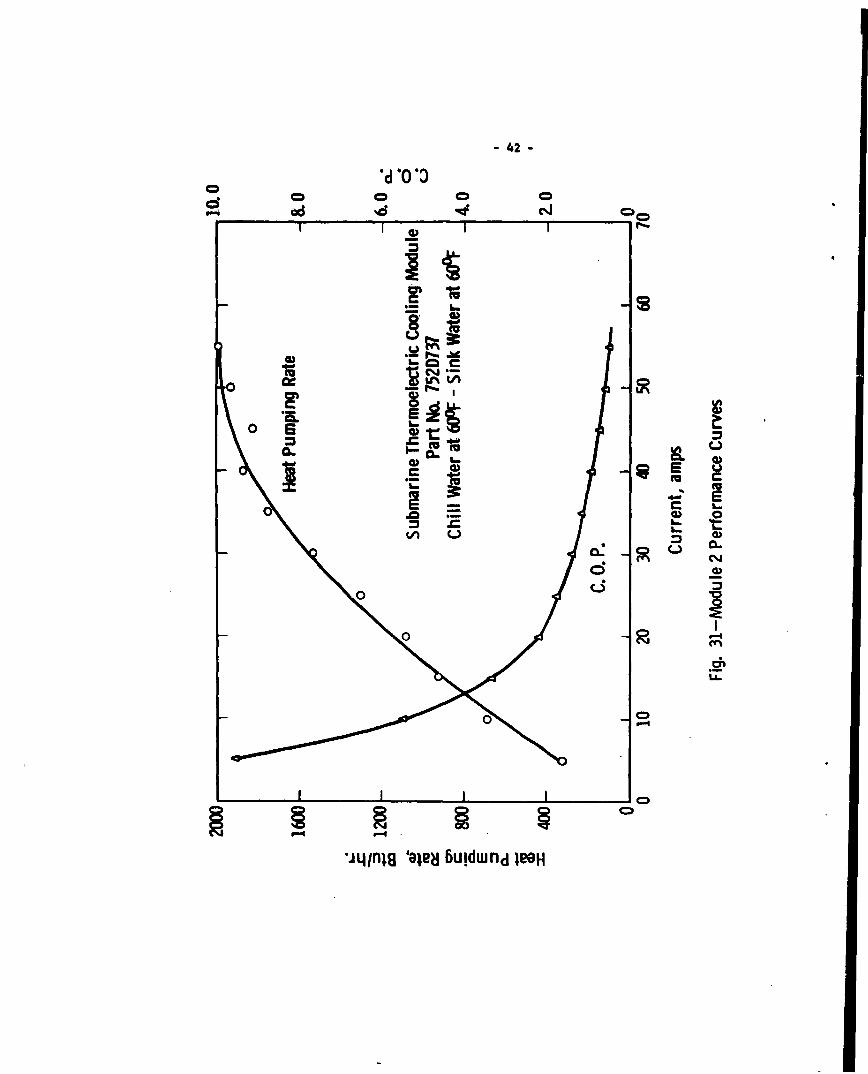
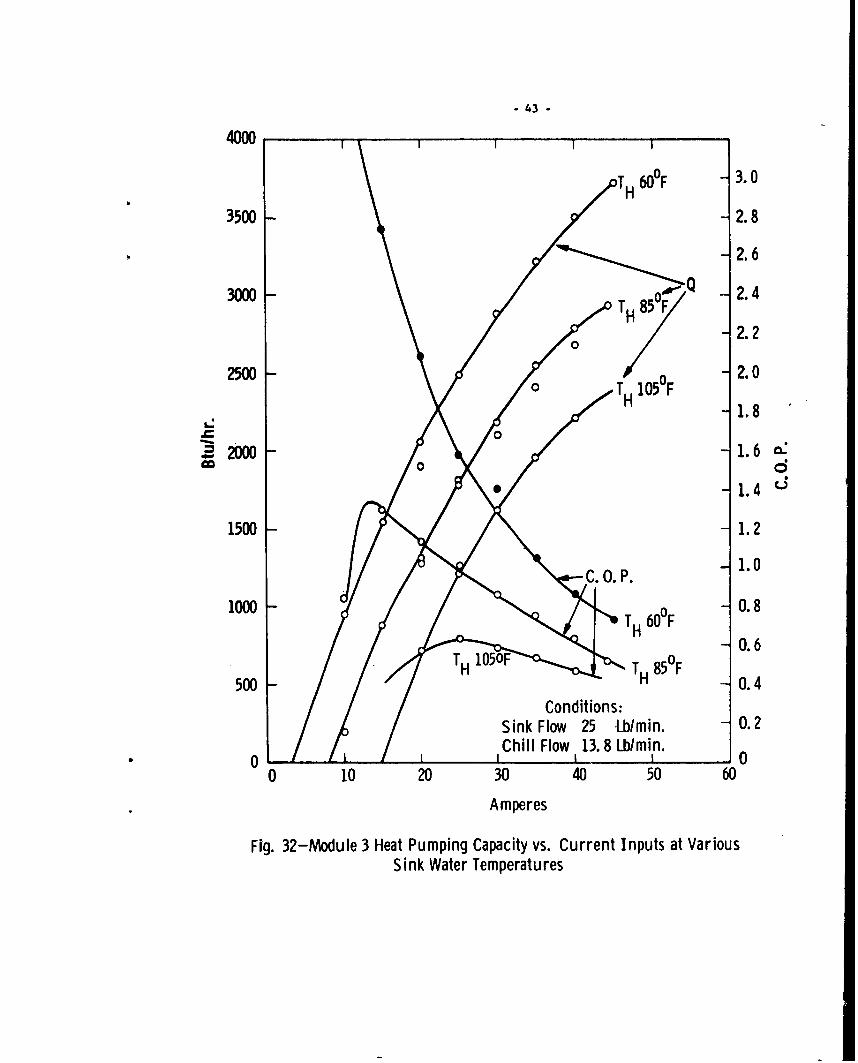
As stated previously the third module was to be a prototype of a shipboardinstallation. Beyond obtaining optimum performance in minimum size and weight themain considerations were that the unit should meet the usual Navy shock and vibrationtests and that it should be easily stacked into larger capacity units. The featuresof this module were, the cupro-nickel cast in aluminum heat exchangers, the sprayedon hot junction copper straps, the headers for ease of stacking, and the use of 432thermoelectric couples with a Z value of 2.75 x 10"31/C. The size of the unit wasreduced to one foot by one foot by three inches. Although the weight increased to50 pounds. The performance obtained is shown in Figure 32 for various values ofchill and sink water temperatures. The variation of the heat pumping rate withwater flow was measured as shown in Figures 33 and 34. The optimum values were thenused 'to run the performance curves. An attempt was made to measure the temperaturedifferential between the junction straps and the chill and sink water. Four copper-constantan thermocouples were placed on various cold junction straps, and four onvarious hot junction straps. These temperatures were read during the performancetests and the spread of values is shown in Figure 35. The accuracy of these readingsis doubtful because of the difficulty in soldering the thermocouples in the correctposition.
Since it is necessary to pump both the chill and sink water through module,the pressure drop across the module is a measure of the energy expended in doing so.This pressure drop represents a loss which directly subtracts from the performanceof the module as it adds heat to the water. The variation of the pressure drop withvarious flows is shown in Figure 36 for both the chill and sink water heat exchangersThe sink water pressure drop is approximately twice the chill water pressure drop asthe sink heat exchanger is essentially two chill heat exchangers.
The witnessed results of both the shock and vibration tests of the thirdmodule are shown in Appendix III and IV. No effects due to the tests were notedeither during or after the tests. A check of the heat pumping performance was madeafter the tests and no change was observed.
VIII. Conclusions
The end result of this contract has been the construction of a thermoelec-tric air conditioning unit which could be used aboard a submarine using a water-to-water type of air conditioning system. This unit is rated at 2550 BTU/hr at acoefficient of performance of 0.75under the conditions of 85 0 F sink water and 55°Fchill water. The direct current which must be supplied to the unit for this per-formance is 35 amperes with a ripple content less than 5 per cent.

-40
*d -0 -0
0~
EE
CD
C 0L)
U m
C
00L. (U 0
*jL/fllg 'an2~ Buldwfd W2H

- 41-
*d .0 30oc 00cm
CC
C ~CD
.D - E~0
m0
V) u
0 0 Li 2 4
CD2CD0
,9q-a- 'ee Cuw dIO
-42-
d~s 00 0 0
adq %d ciJ
0) F
CL u
0 ci
CLLL
lLI4fllg 'aledj 6uidwnd 1BGH
43 -
4000
T 60°F 3.0
3500 - 2.8
-2.6
3000 0850 -2.4T H 82.2
2500 T - 2.00 T H 10 5 °0F1 .H -1.8
1.4 L
1500 - 1.2
OP. 1.0
1000 - TH 60OF0.8
0.650T H 10O T H 85°0F0.500-0.
S~Conditions:
Sink Flow 25 Lb/min. 0.2Chill Flow 13. 8 Lb/min.* 0 II 0
0 10 20 30 40 50 60
Amperes
Fig. 32-Module 3 Heat Pumping Capacity vs. Current Inputs at VariousSink Water Temperatures

- 44-
120 1 1 1 1 1
110
100
90
80
~70
6O0
0~•'50--
40-
30Conditions:
20 - Chill Water in at55 FSink Water in at 85°F
10 - Input Current 35 Amp.
0 1 1 1 10 10 20 30 40 50 60 70 80 90 100
Percent Flow of 40 Lb/min.
Fig. 33-Module 3 Variation of Heat Pumping Capacity vs. Chill Water Flow
- 45 -
1.0-
0.9
0.8
_ 0.7-
0.6-
, 0.5-
0.4-0.3-
0.2-
0.10 I I II,
0 1 2 3 4 5
Sink Water Flow, GPM
Fig. 34-Module 3 Variation of Heat Pumping Capacity vs. Sink Water Flow

-46 -
CD C

- 47 -
55
Hot Heat Exchanger
50
45
40
35
30
Cold Heat Exchanger
25
020
15
10
5Water at Amb. Temp.
00 1 2 3 4 5 6 7 8
GPM
Fig. 36-Module 3 Pressure Drop vs. Water Flow Thru Heat Exchangers

"- 48 "
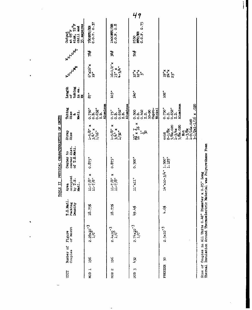
During the period of this contract two other experimental units were con-structed along with a 2 cubic foot freezer suitable for use in connection with awater-to-water air conditioning system. The physical characteristics of theseunits are shown for comparison in Table II. On the basis of the results obtainedfor the shipboard module at a coefficient of performance of one a ton of air condi-tioning could be obtained at a weight of 353 pounds and a volume of 1.76 cubicfeet.
In weighing the suitability of this type of system for submarine installa-tion the characteristics other than capacity, weight and size should be pointedout. By itself a thermoelectric unit as described here is noiseless. The onlynoise would come from pumps necessary to circulate the water or possibly from powersupplies and controls necessary to drive the unit. This type of unit is readilyassembled into different capacity units. This is a desirable feature in that itpermits easier installation within cramped quarters and can also be almost exactlysized to a particular application. Ease of assembly of unit is also an importantconsideration for the replacement of any units which become defective. Althoughbecause of the inertness of the unit, the life should be exceptionally long. Afeature of this device which is noteworthy is that sea water can be used directlyin the unit. This means the sink water is at the lowest possible temperature. Noadditional heat exchangers with their attendant increase in temperature are neededto keep the sea water pressure from damaging the unit. This advantage is gainedby using cupro-nickel tubing in the units capable of withstanding over 2000 psi.
The main disadvantage of a thermoelectric unit is of course the cost ofthe thermoelectric material. It should be remembered that these materials arestill in the early stage of development and price reductions are certainly fore-seeable. In this respect, techniques are already available whereby thinner thermo-electric materials can be made and incorporated into the module presented here.This would not only reduce the amount of material but would increase the performanceof the unit.
Other than improvement in thermoelectric material there are at least threeareas within which improvement can be made to gain better overall performance ofthe unit. The first and most important of these is the electrical insulationbetween the junction straps and the heat exchangers. As the heat flow must passthrough this insulation it must be a good thermal conductor or so thin that thethermal loss across it can be neglected. On this unit, this insulation was pro-vided by an aluminum oxide flame spray. Because of the porous nature of the cast,aluminum heat exchangers more oxide than desired had to be sprayed on to providethe necessary electrical insulation. A pressure casting of the heat exchangerwould produce a more dense material and a much thinner coat of oxide could be used.The second area concerns the weight of the unit; Approximately 30 pounds of thetotal 50 pounds is in the heat exchangers. Since the tubing in the heat exchangershas an outside diameter of 1/2 inch an obvious saving in weight could be made byimproving the tolerance control in the casting technique so that the heat exchangerthickness could be reduced from 3/4 inch to 1/2 inch. This would represent anapproximate reduction in weight of 10 pounds or 20 per cent. The final area ofimprovement concerns the water pressure drop through the heat exchangers. Sincethis pressure drop represents a loss chargeable to the performance of the unit
- U'
,,,U I E0 04rO
00
4 UN -cti 4
go~c a 4\ 9I~ ~ ~ r.1- '0 A Iit c
06oo0 0 0 H'=4 ; C
+3l 0Ea- 1, - 4 A M U vL 'IU -
4-4
04 4
03 U 0
00
-H ~ ~ -C--l)-0-1 0
0, 10- 0 ý

-50
reduction of the loss is well worthwhile. This drop can be greatly reduced by theuse of a circular coil design which has already been devised that eliminates thepresent 180* return bends. The pressure drop has been lowered by9O per cent with-out any anticipated lose in heat exchanger performance. All these areas are relatedin that they represent an improvement in heat exchanger design which has been theobjective throughout the project.

- 51 -
APPENDIX I MOD=LE DESIGN CAIXULATIO1
Chill Water Flow Required
Under the original specifications a ton of air conditioning was to be
produced with inlet and outlet water temperatures of 550F and 500F respectively.
These requirements determined the water flow as follows:
W - lb/hr of water
hl= enthalpy of water at t1 7 50°F
h2 - enthalpy of water at t2= 550 F
hu'ti - 32OF
h t2- 320F
V- BT/HR of cooling
_____ r 12,134 .-2426lb/hrorw h 2 t 2 - .85gal/min.
The importance of this figure changed when the construction of the module was
changed so that the water flow could be connected in series or parallel in stacked
units. The water flow through each module then 'becomes whatever is necessary
or desirable. The optimum flow for the third module by tests turned out to be
13.8 pounds /minute or 1.65 gallons/minute.
Chill Water Velocity Through Neat Exchau r
Inside Diameter of Tubing - 0.404 inches
Water Flow = 13.8 pounds/minute
1.65 gallons/minute
0.22 cubic feet/minute

- 52-
The velocity through the tubing would be,
UMwA
where Um a velocity in feet/second
W = water flow in cubic feet/second
A = cross-rectional area of tubing in square feet
0.22U (0.202)' x - 4.12 feet/second
The Reynolds number would be,
dG
where d = inside dimneter of tubing in feet
G = mass velocity, 13.8 b/ix61 106r (C).202)= r-l/h
S= viscosity, 3.17 lb/hr ft 0 500?
0.400 x0.93 x 10 4NEI 3.17 x 1 X10
Temperature Drop Between Tubing and Water
The heat transfer area for 140 inches of the 0.404 inch I.D. cupro-
nickel tubing in each heat exchanger is,
r o.4o0•x 14o0Ah = ~ -144 - 1.23 sare feet
"- 53 -
The Prendtl number of water at 50OF would be,
KPR =K .334
where i = dymanic viscosity, 3.17 lb/hr ft
C- heat capacity, 1 BTU/Ib OF
K = thermal conductivity, 0.334 BTU/hr ft 0F
The Nusselt number for a Prandtl number of 10 according to the Martinelli
equation as found in "Principles of Engineering Beat Transfer" by W. H. Giedt
and a Reynolds number of 104 would be,
Nu n 80
The heat transfer coefficient of the heat exchangers would be,
h K 80xo.0ý34x 2h d 0.404
h = 794 BTU/hour, foot 2, O
The temperature differential from the water to the tubing for each 1000 BTU/hdur
of heat pumping is then,
A T --hA
n
1000 =loOA T - O 7-1.07.
7(94 x 1.23

- 54 -
The calculations for the sink heat exchangers would differ with respect to
the water temperature and flow, which were 850F and 25 pounds/minute. The
results of the calculations are listed below.
U - 7.45 feet/second
S= m2.06 1b/hr.ft @ 850F
'is - 1.8 x l04
Ah - 1.23 square feet
K -0.351 BTU/hour, foot, OF • 85oF
N 5.87
%U1U120
h - 1250
AT a 0.8 OF per 1000 m¶.J/hour
Beat Loss Sink and Chill Beat Exchangers
Total Area - 12 inches x 12 inches - 114 square inchemor 1 square foot
The pellet area of 432 pellets of 0.420 inch diamter and 0.25 inches
long is,
1432 x (0.210)2 7 = 60 square inches
The effective area1. 1144 mims 60 or 84 square inches. Using a thermal
conductivity of 0.2 BTU/hour, inch, foot 2 , 0 F and a maximm temrature differ-
ential of 100OF minus 45°F, the heat leakage for 1/2 the module becaes,
Q IL AT - 0.2 x 5 I
For the whole module the leakage in twice this or 88 BmU/hour.
- 55 -
The heat pumping ability of a thermoelectric pellet is calculated by
solving the heat pumping equation:
Q r I - 1/2 R i2 - LA (Th - TA)
where r - average Peltier coefficient for a couple
I - D.C. current plus a ripple factor
R = one half total couple resistance
K - average thermal conductivity of the thermoelectric couple
A - cross-sectional area of a pellet
L = length of a pellet
Thu hot junction temperature
T = cold junction temperaturec
Solving of the equation in this manner one can obtain a family of
curves of heat pumping versus input current at various hot junction temperature
and a specific cold junction temperature. This computation is easily done on
a computor. An example of the curves obtainable is shown in Figures 37 and 38.
The coefficient of performance is obtained by the equation,
C.0O.P.
where Q = heat pumping rate
I = D.C. input current
S- Peltier coefficient
R - total circuit resistance

- 56 -
3000
2.8 TH .65 F H 65.F0
jIF"TH.?5°F
2.4 -THul75F 0He85F - 2500
2.0 Heat Pumping -2000
1.6 TH85F1500.6
CM
1.2
=3
0.8
TH- 95OF . .5000.4 -
0 1Il Ic0 20 40 60 80 100
Current, amperes
Fig. 37-Module 3 Calculated Performance with Z of 2.6 for 112 Module

- 57 -
3.2 T 3200
T HO7 5 0F
2.8 -TH 0F 28008THz 75°F TH= 65°F TTH-85°F
T HO 95 0F
2.4 2400Heat Pumping
2.0 2000TH 85°F
6 1.6 1600d g
E
1.2 - 1200o
0.8 - -800
TH = 950F
0.4 -- 400
0 I I I I 00 20 .40 60 80 100
Current, amperes
Fig. 38-Module 3 Calculated Performance with Z of 2. 95 for 112 Module

-58-
The curves obtained in this minner are independent of the heat
exehugers used on the hot and cold Junctions. Nov closely the performance
of a completed unit would follow these curves depends on the ability of the
heat exchangers to remove the heat without additional teaperature drop. A
perfect heat exchanger would be one in which the water vat at the eme temper-
ature as the thermoelectric junctions.

- 59 -
APPUDIX II FREEZER IMIGN CAICULATION0
Neat Leakage Into Box
The vp.rious inside areas of the freezer were first determined.
LI - Top and bottom 16 x 17 1/2 x 2 - 560 uq in or 3.9 sq ft
L2 - Sides 13 1/2 x 17 1/2 x 2 - 472 sq in or 3.3 sq ft
Q3 - Door 13 1/2 x 16 - 216 sq in or 1.5 sq ft
L4 - Thernoelectric unit 13 1/2 x 16 - 216 sq in or 1.5 sq ft
The polyurethane foam used for insulation was 4 inches thick in the
top, bottom, and sides, 3 inches thick in the door, and 3/4 inch thick between
the hot and cold plates of the thermoelectric assembly. A value of 0.2 BTU/hr.,
inch, ft 2, OF was used for its thermal conductivity. A maximum ambient of
85°F was considered outside the freezer and an internal air temperature of
-10 0F. Using the basic equation for heat flow by conduction,
the various leakage were determined.
S =-0.2 x 9= 18.5 BTUJ/hr
=0.2 x 3.3 x -9 15.7 BTU/hr
= 0.2 x 1.5 x - 9.5 VTU/hrQL3 = 4
-8)-
To obtain the heat leakage of the thermoelectric unit the area
occupied by the pellets maet be subtracted from the total area to obtain
the effective an&. 100 pellets with diameter of 0.120 inches and 0.Pr
length were used in the assembly. The pellet cross-sectional r*ea vas,
2100 x r (0.210) 1 13.9 square inches or 0.1 square feet
As the sink water used in the thermoelectric unit will be between
500 - 60°0 the temperature differential between the hot and cold plates will
be from 6o00 to -1o00 or lopr. Therefore.,
0.2 - 26.2 MU/hrQL4 - 0.75
The total heat leakage into the freezer box would be,
S- 18.5 + 15.7 + 9.5 + 26.2 a 70 MTs/hr
This would be the steady state load on the thermoelectric unit in an ambient
of 850F.
Cold Side Beat Exchanner
The heat was transferred inside the freezer to the thernoelectric
junctions by means of a finned natural convection heat exchanger. It was
cauposed of 30 aluminm fins, 0.032 inches thick.. 12 inches thick, and 1.5
inches long. The spacing between fins was 0.5 inches . The heat load to be
exchanged was the total pumping load less the leakage throug the thermoea ctric
unit or 43.8 DTJ/Ihour.
Fin area-7155 x 12 x 30 x 2Fin• "rs 4 7.5 sqauare feet

- 61-
The fin efficiency was determined by the equation,
|7F tanh m=F m
wher tm
S= length of fin in feet
h = heat transfer coefficient
t = thickness of fin in feet
K = thermal conductivity of fin, 170 BTU/hour, foot F
For this type of finned heat exchanger the convective heat transfer coefficient
is approximately,
h.-il.0 BTU/hour, ft2 oF
Continuing with the determination of the fin efficiency,
m 427x1x. 1= 2.1-v.03 x I7
tanh 2.1 x 1.5/12 = tanh 0.26F 2.1 x 1.5/12 0.26 1
The temperature difference between the fins and the air inside the freezer
would be,
A T 4= = 5.80F
Hot Side Heat Exchanger
This heat exchanger consisted of 102 inches of 0.65 inch I. D.
aluminum tubing brazed to a flat aluminum plate. The heat transfer area of
this tubing would be,
A r x 0.65 x 10² 1.74 square feet12

- 62-
A water flow of 2426 pounds/hour at 50°F was assumed through the tubing. The
mass velocity was then,
22426 - 1.05 x 10⁶ pound/hour, sauare feet7 = •.(o3-25)7,
The viscosity p, of water at 500F being 3.17 pounds, hour, foot. The Reynolds
number in the coiled tubing was,
IE dO o.65zx.o5x106 -1.8x10⁴"NBC - - 3.17 x 12
The Prandtl number of water at 50°0 would be,
NPIR - K .
vhere :g = dynamic viscosity, lb/hr ft
C P heat capacity, BTU/lb oF
K - thermal conductivity, BTU/hr ft 0F
The Nusselt number for a Prandtl number of 10 according to the Martinelli
equation as found in "Principles of Engineering Beat Transfer" by W. H. Giedt
and a Reynolds number of 1.8 x 10⁴ would be,
NM - 100
The heat transfer coefficient then becomes
h- -- 100 x0.334 x12d 0.65
h -616 BTm/hour,, square foot,, Or

- 63.
From Figure 39 which is a plot of the heat pumping rates versus
coefficient of performance for various figureo of merit, it can b eseen that
the curve, for a figure of merit of 2.59 x 10- 1/C° Is leveling off at a
coefficient of perfozmance slightly over 0.3. Using this value the total
heat to be dissipated in the sink water would be,
'.oý + M + 70 - 230 + 70 -u Do Bo/mur
The temperature difference between the sink water and the hot heat exchanger
would be,
A T 30 - ~~ 0.28OFh• A 616 x 1.74
Time Required to Reach Operating Temperature
Assuming an initial temperature of 90°F and a desired final temper-
ature of O°F the total heat removal necessary was determined.
1. Air within Freezer
Volume - 2.1 cubic feetDensity - 0.072 pounds/ cubic footSpecific Heat - 0.24 BTU/poundOF
q = Vp Cp AT - 2.1 x 0.072 x 0.24 (900 - 00 )
q - 3.26 BTu
2. Cold Plate and Fins
Volume = 0.0342 cubic feetDensity - 170 pounds/cubic fooýSpecific Heat - 0.22 BTU/pound F
q - Vp CP •T 00.342 x 17o x 0.22 (9o + 100 )
q - 128 BTU

-64-
256-
Z 3.46
213-Z 2.88
Z U2.59
170
e 128 Z- 2.16
-.-
82TH -650F
Tc - -1O°FN C , 100F
42.6 - Np IO0
0 I I
0 0.1 0.2 0.3 0.4 0.5 0.6
Coefficient of Performance
Fig. 39-Freezer Heat Pumping vs. C. 0. P. for Various Figure of Merits

"- 65 -
3. Freezer Insulation
Volume = 2.6 cubic inchesDenisty - 5.3 pounds/cubic footSpecific Heat = 0.2 BTU/pound 0F'q = Cp T -T2.6x5.3x0.2( 2" 0°
q = 124 BTU
4. Total Heat to be Removed in One Hour
QT = 3 + 128 + 124 = 255 BTU
In Figure 40 is a plot of the heat pumping rates versus input currents
at various cold junction temperatures for a figure of merit of 2.59 x 10⁻³ /Co.
Since the cold junction Vill almost inmediately reach the hot junction temper-
ature when the sink water is turned on, it is assumed the heat pumping will
start with a cold junction temperature of 50°F. Using a current of 35 amperes
the heat pumping rate would start at 450 BTU/hour and decline to 150 BTU/our
at -10 0F. This would be an average pumping rate of 300 BTU/hour.

- 66 -
560
Z - 2.59 X 10³ i I0C
N- a100
TH. 65OF C0FF
420
,-0°
350O
E 280-
-r210 -- _/ -2100
140-
70-
0 I i I0 10 20 30 40 50
I, amps
Fig. 40-Freezer Heat Pumped vs. Input Current

- 67 -
APPEND IX III-SHOCK TE STS

-68-
'IW
~F j
I It
Od 01 0
C) lot,I~tE a
.0
~~b Is I~
..........,- ,.-. -- -- --- - - - -
-69-
,!i,,)c~k Test Setup
NP 480

-70-
is A40
43 a SI I
433
g. I "-i
-71
44
Figure 42 Second Shock Test Setup
N PM -1489

I - 72-
0
ai
E-4
Al 0p4
NT
N M- 4

73
0
'43
S4I 9~

- 74 -
APPENDIX IV VIBRATION TESTS
Navy Submarine Air Conditioning ModuleI.W.R. 9700-916-R-721133Vibration Tests as per MIL-STD-167Nobs 77095Unit energized with 35 Amps. and 26 voltsPhoto #370119
Fore and Aft
Exploratory Vibration (Par .3.1.4.3.1)9 C.P.S. to 33 C.P.S. .010 in. Amplitude No Resonant Points
Variable Frequency Test (Par. 3.1.4.3.7,* (5 min. at each point)9 C.P.S. to 15 C.P.S. .030 in. Amplitude
16 C.P.S. to 25 C.P.S. .020 in. Amplitude26 C.P.S. to 33 C.P.S. .010 in. Amplitude
Endurance Test (Par. 3.1.4.3.3) 2 Hours
33 C.P.S. .010 Amplitude
Athwart Ships
Repeated Tests of Par. 3.1.4.3.1, 3.1.4.3.2 and 3.1.4.3.3.
Vertical
The vertical position was simulated by mounting unit 900 toVibration Table. (See Photo #370122).
Exploratory Vibration (Par. 3.1.4.3.1)9 C.P.S. to 33 C.P.S. .010 in. Amplitude Resonance at 31 C.P.S.
Variable Frequency (Par. 3.1.4.3.2) (5 min. at each point)9 C.P.S. to 15 C.P.S. .030 in. Amplitude
16 C.P.S. to 25 C.P.S. .020 in. Amplitude26 C.P.S. to 33 C.P.S. .010 in. Amplitude
Endurance Test (Par. 3.1.4.3.3) 2 Hours29 C.P.S. .010 Amplitude
These test Results Observed by J. Berg, Navy Inspection Dept. Also witnessedby E. Frantti and J. Duch, New Products, Central Laboratories.
Tested by Walter Payne, 2-LRwy Lab., East Pittsburgh, Pa.

- 75 -
DISTRIBUTION LIST
Mr. M. J. Pistilli, Office of Inspector of Naval Material, 401 Old PostOffice Building, Tittsburgb 19, Pennsylvania.
Mr. R. T, Fiske, Marine Department, Westinghouse Washington Office (3)
Mr. B. J. Wilson (Code 5230), Director, U. S. Naval Research Lab.,Washington.
Lt. Cdr. J. Woolston (Code 241E), Commander, Portsmouth Naval Shipyard,Portsmouth, New Hampshire.
Mr. R. J. Kirkpatrick, Headquarters Engineering Staff, Research Labs,Pittsburgh, Pennsylvania.
Mr. W. G. Evans, Project Manager, New Products Laboratories, ChurchillBoro, Pgh. 35, Pa.
Mr. J. D. Meess, Supervising Engineer, New Products Laboratories, ChurchillBoro, Pgh. 35, Pa.
Mr. G. W. Nagel, Advisory Engineer, New Products Laboratories, ChurchillBoro, Pgh. 35, Pa.