un_all_-cpp
DESCRIPTION
EDM Machine detail study and vrious mechanical processesTRANSCRIPT
ELECTRIC DISCHARGE MACHINING (EDM)INTRODUCTION
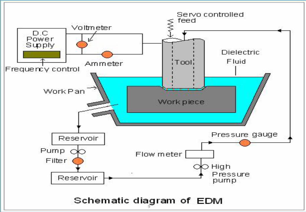
EDM - process of machining conductive materials using sparks occurb/w an electrode and a w/p in presence of a dielectric fluid.
Advantages are: accuracy, surface quality and fact that hardness andstiffness of w/p material is not important for material removal.
EDM can cut small or odd-shaped angles, intricate contours orcavities in extremely hard steel and exotic metals such as titanium,hastelloy, kovar, inconel and carbide.
1
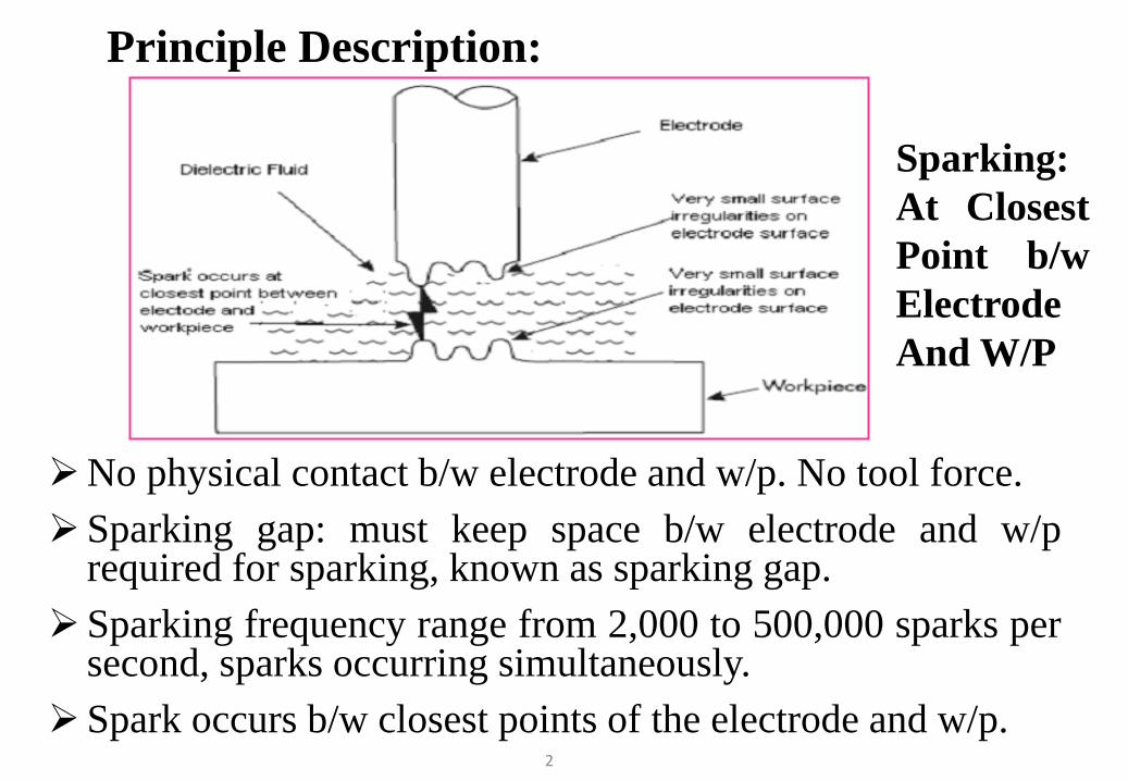
Principle Description:
No physical contact b/w electrode and w/p. No tool force.Sparking gap: must keep space b/w electrode and w/p
required for sparking, known as sparking gap.Sparking frequency range from 2,000 to 500,000 sparks per
second, sparks occurring simultaneously.Spark occurs b/w closest points of the electrode and w/p.
Sparking:At ClosestPoint b/wElectrodeAnd W/P
2
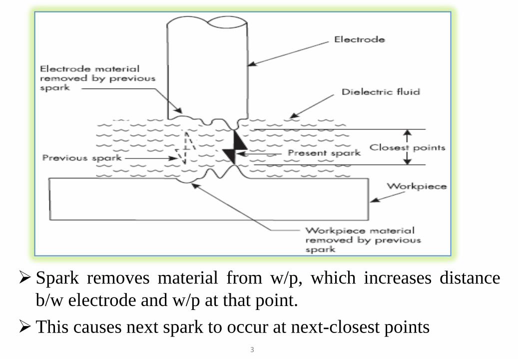
Spark removes material from w/p, which increases distanceb/w electrode and w/p at that point.
This causes next spark to occur at next-closest points3
EDM is a thermal process; material is removed by heat,Due to flow of electricity in the form of a spark.
Material at where spark originates and terminates, areheated to the point of vaporization.
While electrode and w/p should never feel more than warmin EDM, but the area where each spark occurs is very hot.
The area heated by each spark is very small so the dielectricfluid quickly cools the vaporized material.
4
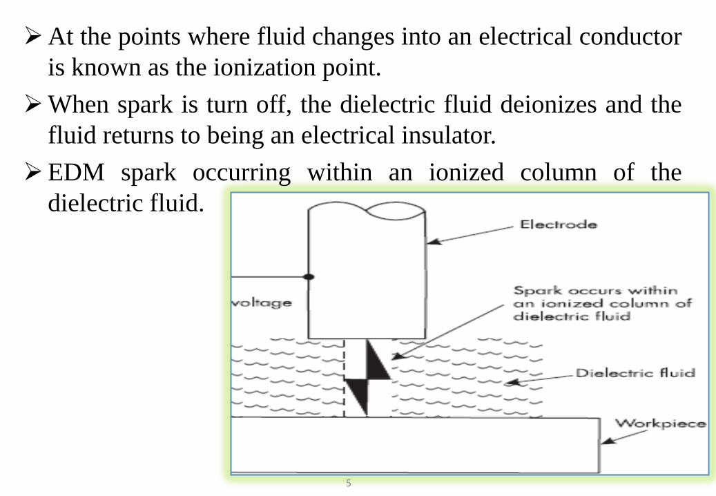
At the points where fluid changes into an electrical conductoris known as the ionization point.
When spark is turn off, the dielectric fluid deionizes and thefluid returns to being an electrical insulator.
EDM spark occurring within an ionized column of thedielectric fluid.
5
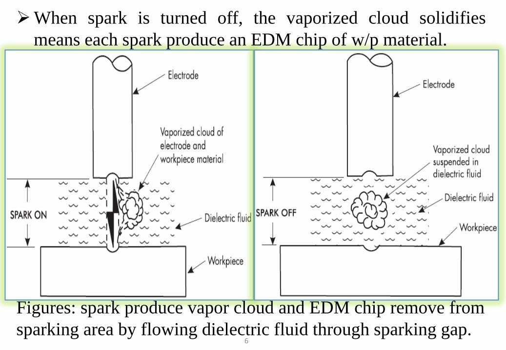
Figures: spark produce vapor cloud and EDM chip remove fromsparking area by flowing dielectric fluid through sparking gap.
6
When spark is turned off, the vaporized cloud solidifiesmeans each spark produce an EDM chip of w/p material.
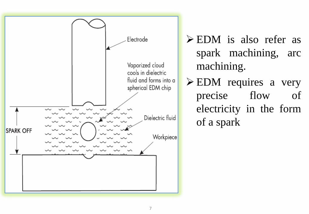
EDM is also refer asspark machining, arcmachining.
EDM requires a veryprecise flow ofelectricity in the formof a spark
7
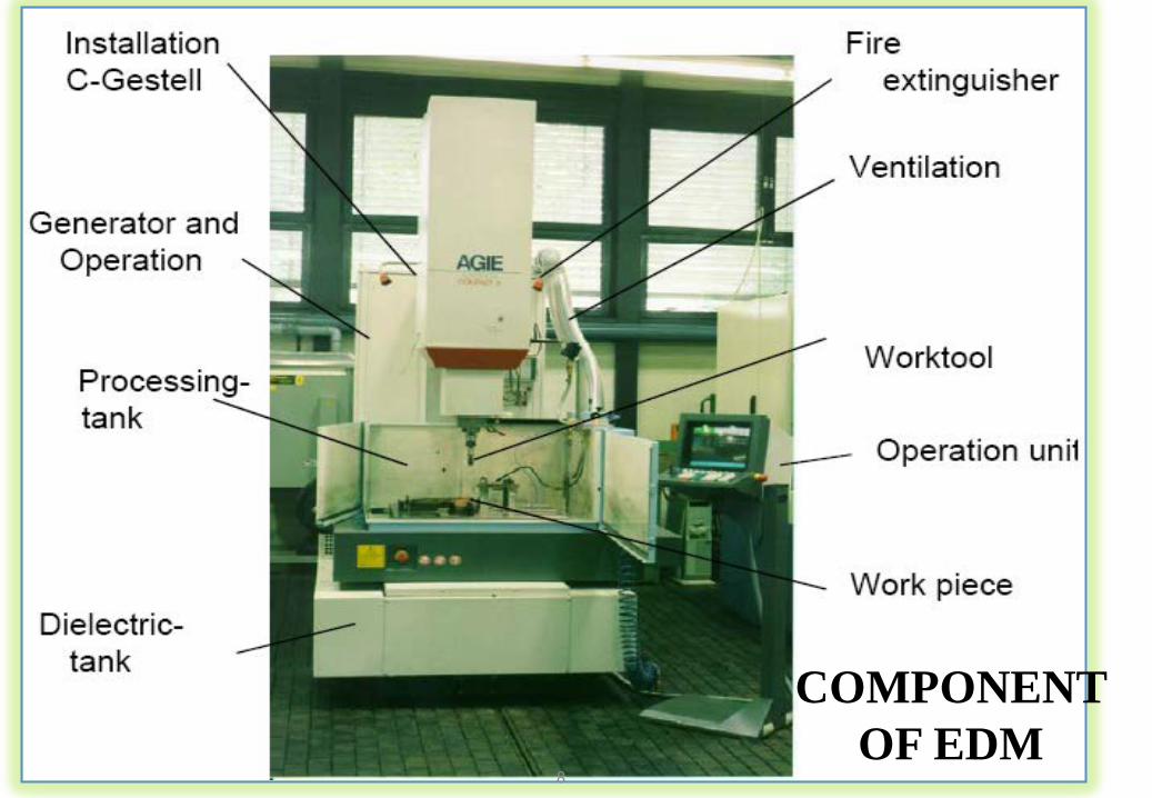
COMPONENT OF EDM
8
9
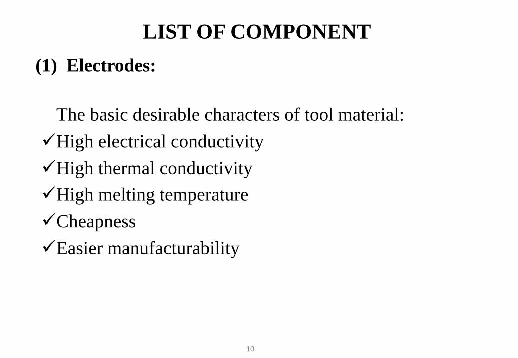
LIST OF COMPONENT(1) Electrodes:
The basic desirable characters of tool material:High electrical conductivityHigh thermal conductivityHigh melting temperatureCheapnessEasier manufacturability
10
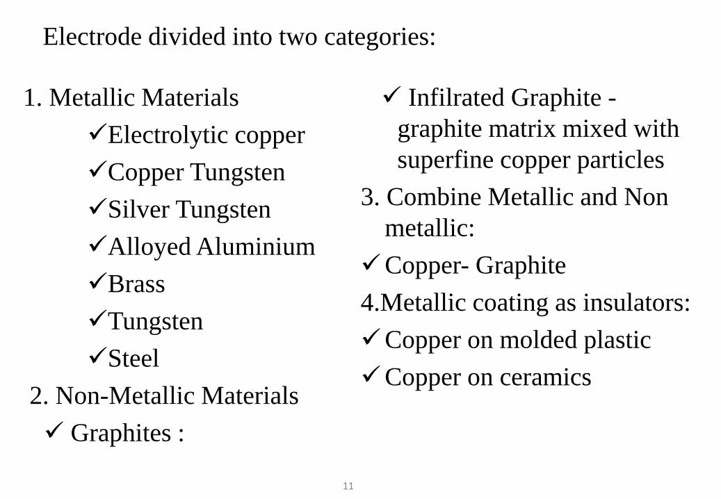
1. Metallic Materials Electrolytic copperCopper TungstenSilver TungstenAlloyed AluminiumBrassTungstenSteel
2. Non-Metallic Materials Graphites :
Infilrated Graphite -graphite matrix mixed with superfine copper particles
3. Combine Metallic and Non metallic:
Copper- Graphite4.Metallic coating as insulators: Copper on molded plastic Copper on ceramics
Electrode divided into two categories:
11
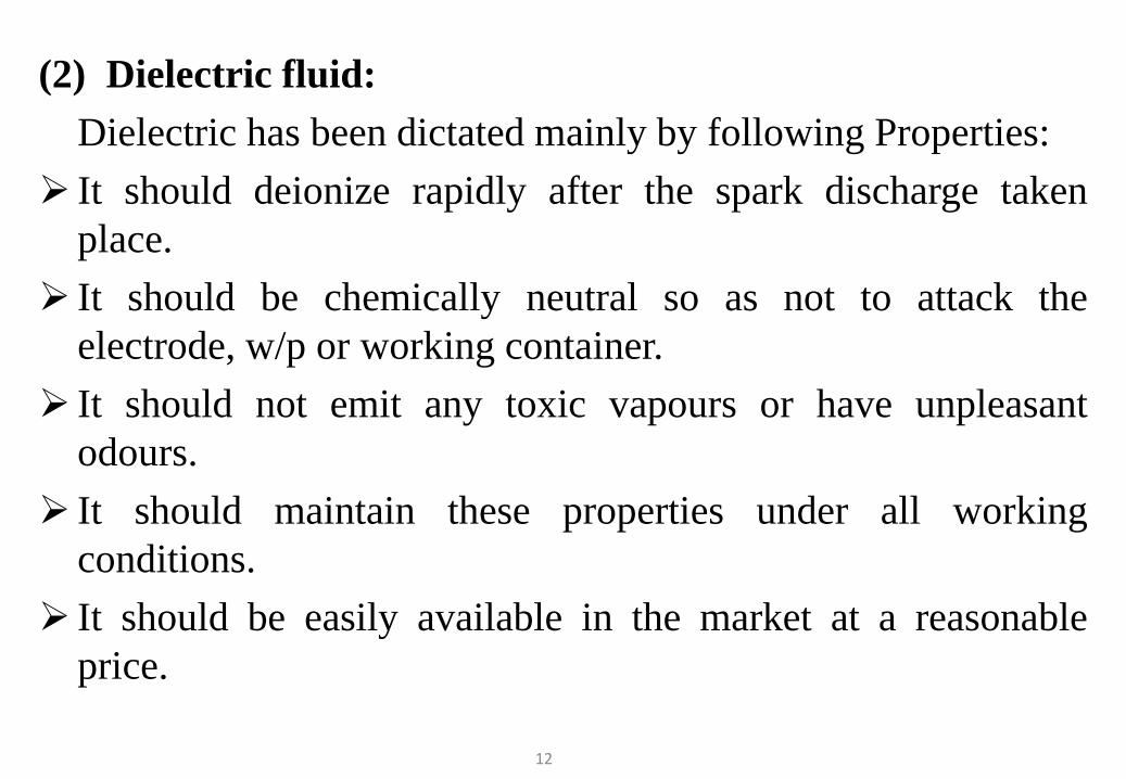
(2) Dielectric fluid:Dielectric has been dictated mainly by following Properties:
It should deionize rapidly after the spark discharge takenplace.
It should be chemically neutral so as not to attack theelectrode, w/p or working container.
It should not emit any toxic vapours or have unpleasantodours.
It should maintain these properties under all workingconditions.
It should be easily available in the market at a reasonableprice.
12
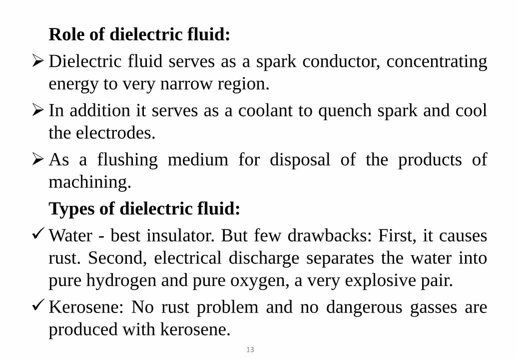
Role of dielectric fluid:Dielectric fluid serves as a spark conductor, concentrating
energy to very narrow region. In addition it serves as a coolant to quench spark and cool
the electrodes.As a flushing medium for disposal of the products of
machining.Types of dielectric fluid:
Water - best insulator. But few drawbacks: First, it causesrust. Second, electrical discharge separates the water intopure hydrogen and pure oxygen, a very explosive pair.
Kerosene: No rust problem and no dangerous gasses areproduced with kerosene.
13
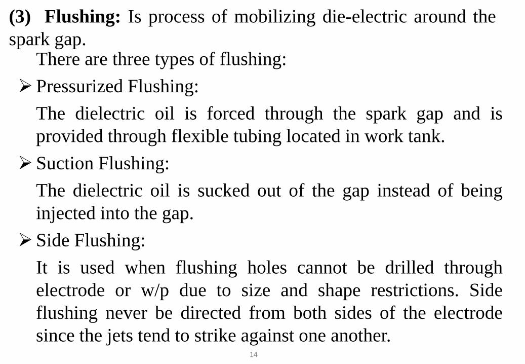
There are three types of flushing:Pressurized Flushing:
The dielectric oil is forced through the spark gap and isprovided through flexible tubing located in work tank.
Suction Flushing:The dielectric oil is sucked out of the gap instead of beinginjected into the gap.
Side Flushing:It is used when flushing holes cannot be drilled throughelectrode or w/p due to size and shape restrictions. Sideflushing never be directed from both sides of the electrodesince the jets tend to strike against one another.
14
(3) Flushing: Is process of mobilizing die-electric around thespark gap.
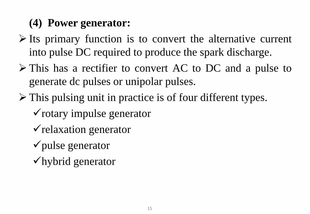
(4) Power generator: Its primary function is to convert the alternative current
into pulse DC required to produce the spark discharge.This has a rectifier to convert AC to DC and a pulse to
generate dc pulses or unipolar pulses.This pulsing unit in practice is of four different types.rotary impulse generatorrelaxation generatorpulse generatorhybrid generator
15
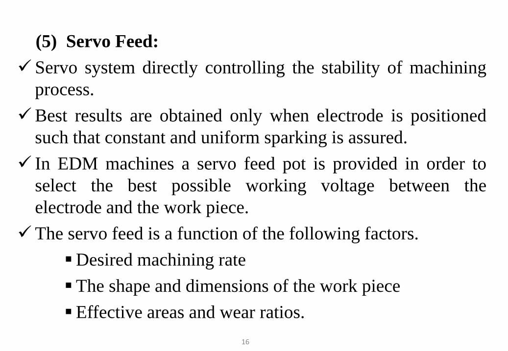
(5) Servo Feed: Servo system directly controlling the stability of machining
process.Best results are obtained only when electrode is positioned
such that constant and uniform sparking is assured. In EDM machines a servo feed pot is provided in order to
select the best possible working voltage between theelectrode and the work piece.
The servo feed is a function of the following factors.Desired machining rateThe shape and dimensions of the work pieceEffective areas and wear ratios.
16
Servo system is operate by taking feed back from gapvoltage sensor system. If sensor gives the feed back withbridged the gap, servo system will react by reversingdirection un till gap clearance by flushing.
So, the selection of flushing technique has direct effect onfunction of servo system b’s if proper flushing will not occurmost of the time of servo system will consume formaintaining gap.
17
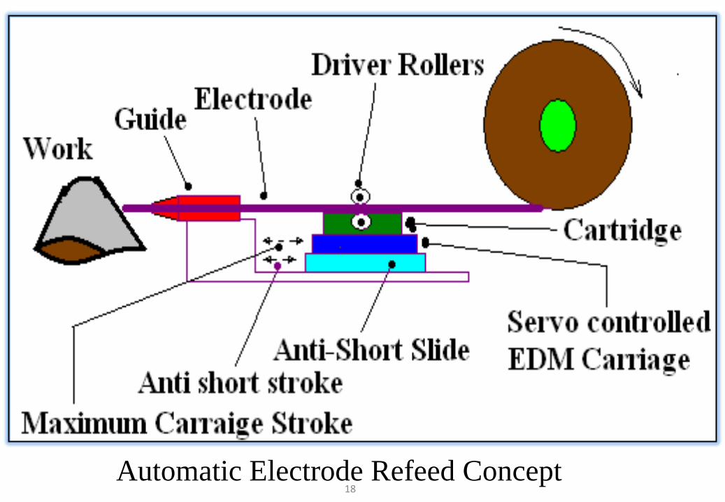
Automatic Electrode Refeed Concept18
Merits and Demerits of EDM
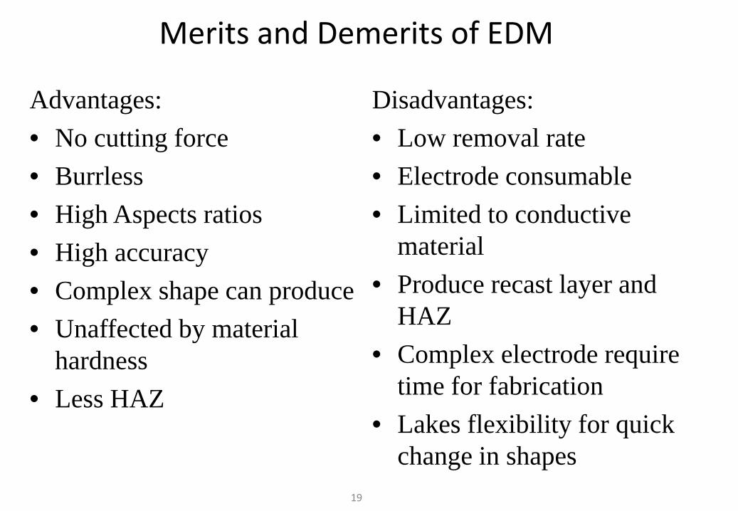
Advantages:• No cutting force• Burrless• High Aspects ratios• High accuracy• Complex shape can produce• Unaffected by material
hardness• Less HAZ
Disadvantages:• Low removal rate• Electrode consumable• Limited to conductive
material• Produce recast layer and
HAZ• Complex electrode require
time for fabrication• Lakes flexibility for quick
change in shapes19
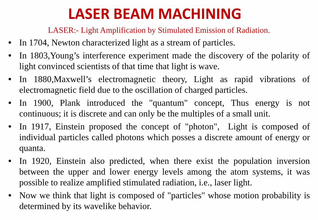
LASER:- Light Amplification by Stimulated Emission of Radiation.• In 1704, Newton characterized light as a stream of particles.• In 1803,Young’s interference experiment made the discovery of the polarity of
light convinced scientists of that time that light is wave.• In 1880,Maxwell’s electromagnetic theory, Light as rapid vibrations of
electromagnetic field due to the oscillation of charged particles.• In 1900, Plank introduced the "quantum" concept, Thus energy is not
continuous; it is discrete and can only be the multiples of a small unit.• In 1917, Einstein proposed the concept of "photon", Light is composed of
individual particles called photons which posses a discrete amount of energy orquanta.
• In 1920, Einstein also predicted, when there exist the population inversionbetween the upper and lower energy levels among the atom systems, it waspossible to realize amplified stimulated radiation, i.e., laser light.
• Now we think that light is composed of "particles" whose motion probability isdetermined by its wavelike behavior.
LASER BEAM MACHINING
LASER Principle: Energy Transition
• To explain how laser light is generated, we need first to investigatethe energy transition phenomena in atoms or molecules.
• These phenomena include:1. Spontaneous Emission 2. Stimulated Emission 3. Stimulated absorption 4. Population inversion 5. Gain and Loss
1. Spontaneous Emission According to quantum mechanics, The electron of atoms can take
different energy states, E1, E2, E3…With E1 < E2 < E3…
Lower energy level is more stable then higher energy level, somovement from higher to lower
So electrons at high energy levels tend to decay to low energylevels, the energy difference between the two levels can be given outas electromagnetic radiation.
This process is called “Spontaneous Emission” :
E2 – E1 = hνo
E2= Upper energy level, E1= Lower energy level, h = Plank’sconstant, νo = Frequency of the radiated electromagnetic wave
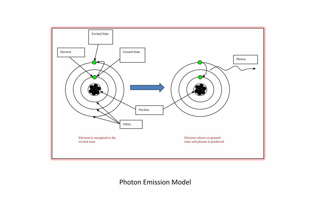
Nucleus
Electron Ground State
Excited State
Orbits
Photon
Electron is energized to the excited state
Electron relaxes to ground state and photon is produced
Photon Emission Model
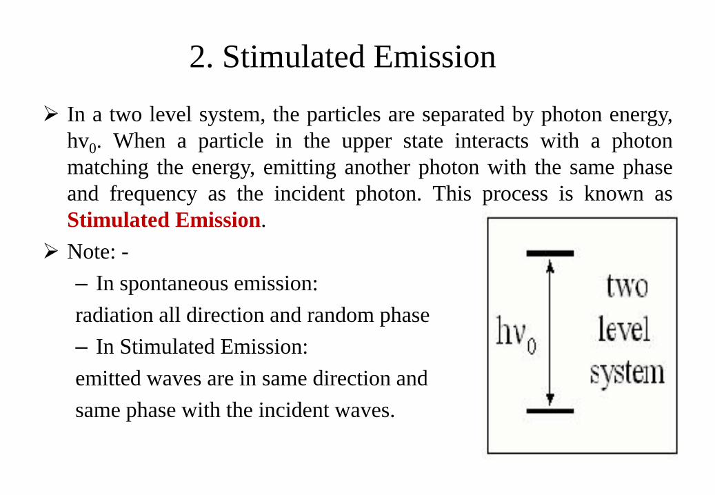
In a two level system, the particles are separated by photon energy,hv0. When a particle in the upper state interacts with a photonmatching the energy, emitting another photon with the same phaseand frequency as the incident photon. This process is known asStimulated Emission.
Note: -– In spontaneous emission:radiation all direction and random phase– In Stimulated Emission:emitted waves are in same direction andsame phase with the incident waves.
2. Stimulated Emission
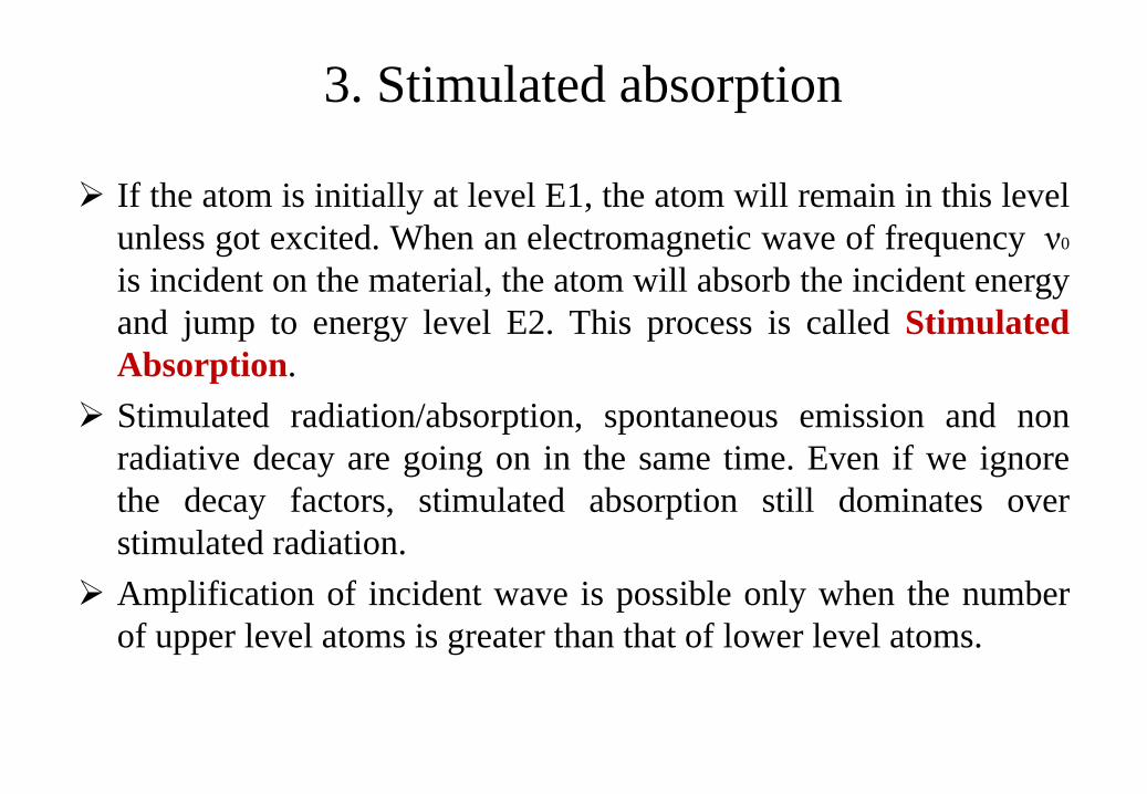
3. Stimulated absorption
If the atom is initially at level E1, the atom will remain in this levelunless got excited. When an electromagnetic wave of frequency ν0
is incident on the material, the atom will absorb the incident energyand jump to energy level E2. This process is called StimulatedAbsorption.
Stimulated radiation/absorption, spontaneous emission and nonradiative decay are going on in the same time. Even if we ignorethe decay factors, stimulated absorption still dominates overstimulated radiation.
Amplification of incident wave is possible only when the numberof upper level atoms is greater than that of lower level atoms.
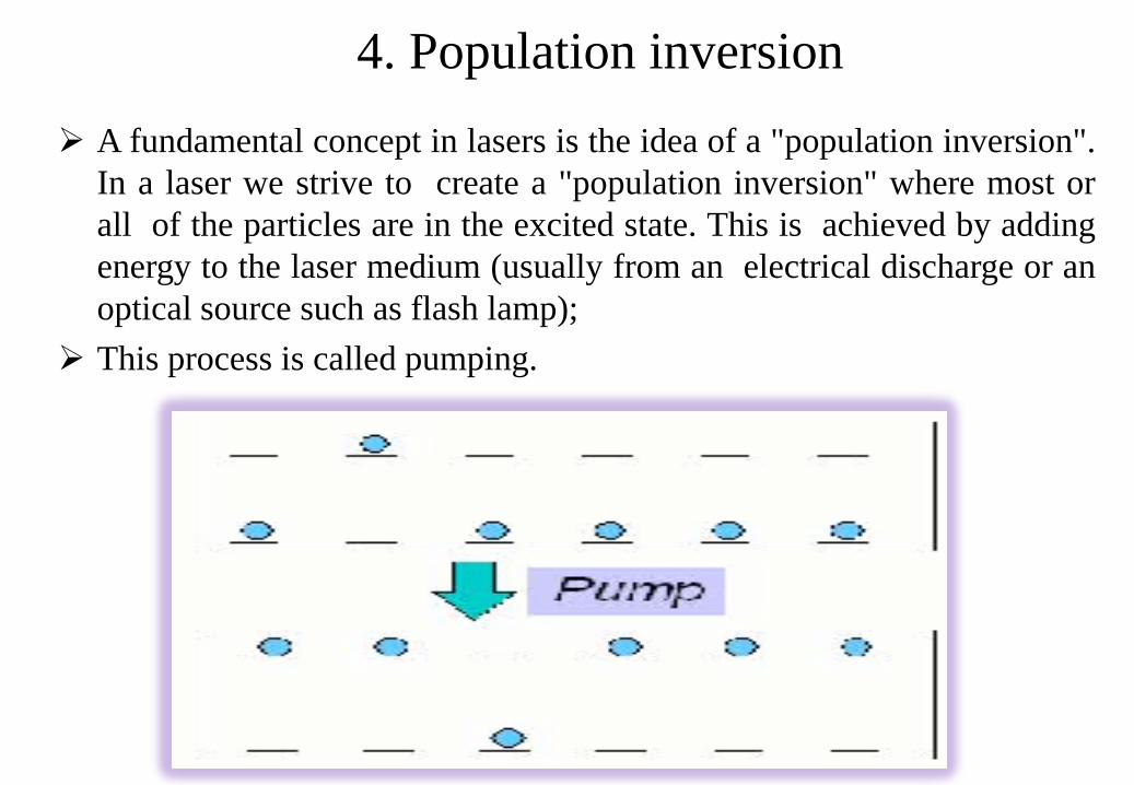
4. Population inversion A fundamental concept in lasers is the idea of a "population inversion".
In a laser we strive to create a "population inversion" where most orall of the particles are in the excited state. This is achieved by addingenergy to the laser medium (usually from an electrical discharge or anoptical source such as flash lamp);
This process is called pumping.
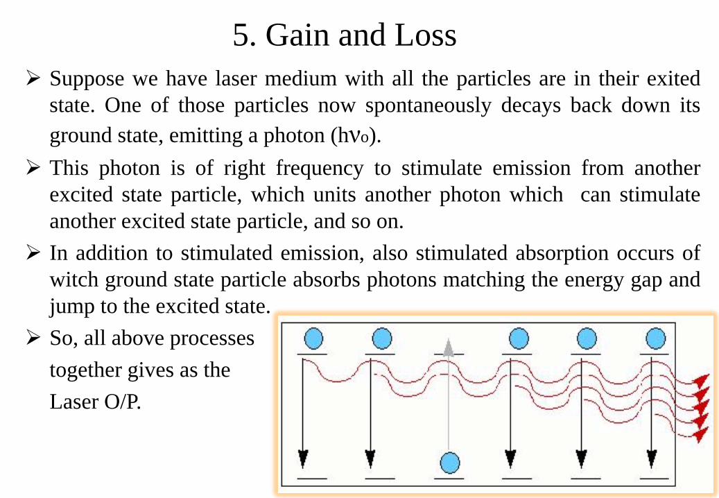
Suppose we have laser medium with all the particles are in their exitedstate. One of those particles now spontaneously decays back down itsground state, emitting a photon (hνo).
This photon is of right frequency to stimulate emission from anotherexcited state particle, which units another photon which can stimulateanother excited state particle, and so on.
In addition to stimulated emission, also stimulated absorption occurs ofwitch ground state particle absorbs photons matching the energy gap andjump to the excited state.
So, all above processestogether gives as theLaser O/P.
5. Gain and Loss

Properties of Laser beam1. Monochromaticity:
This property is due to the following two factors: First, only an electromagnetic wave of frequency V0 can be
amplified called wavelength, this wavelength is decided byhomogeneous broadening factors and inhomogeneous broadeningfactors, this resultant wavelength is very small compared withnormal lights.
Second, the laser cavity forms a resonant system, oscillation canoccur only at the resonance frequencies of this cavity. This leads tothe further narrowing of the laser wavelength. So laser light isusually very pure in wavelength, we say it has the property ofmonochromaticity.
2. Coherence:For any electromagnetic wave, there are two kinds of coherence,spatial and temporal coherence.
Consider a fixed point on the electromagnetic wave front. If at anytime the phase difference between time t and time t+dt remains thesame, where "dt" is the time delay period, we say that theelectromagnetic wave has temporal coherence over a time dt.
We emphasize here that spatial and temporal coherence areindependent. A partial temporal coherent wave can be perfect spatialcoherent. Laser light is highly coherent, and this property has beenwidely used in measurement, holography, etc.
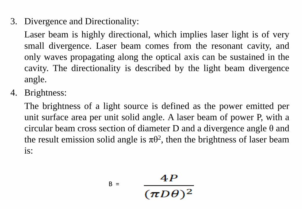
3. Divergence and Directionality:Laser beam is highly directional, which implies laser light is of verysmall divergence. Laser beam comes from the resonant cavity, andonly waves propagating along the optical axis can be sustained in thecavity. The directionality is described by the light beam divergenceangle.
4. Brightness:The brightness of a light source is defined as the power emitted perunit surface area per unit solid angle. A laser beam of power P, with acircular beam cross section of diameter D and a divergence angle θ andthe result emission solid angle is πθ2, then the brightness of laser beamis:
B =
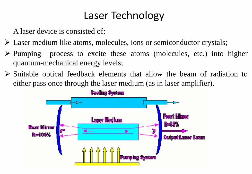
Laser TechnologyA laser device is consisted of:
Laser medium like atoms, molecules, ions or semiconductor crystals; Pumping process to excite these atoms (molecules, etc.) into higher
quantum-mechanical energy levels; Suitable optical feedback elements that allow the beam of radiation to
either pass once through the laser medium (as in laser amplifier).
A laser is constructed from three principal parts:1. An energy source (the pump or pump source),2. A gain medium or laser medium, and3. Two or more mirrors that form an optical resonator.1). Pump source The pump source is the part that provides energy to the laser system. Examples of pump sources include electrical discharges, flashlamps,
arc lamps, light from another laser, chemical reactions and evenexplosive devices.
The type of pump source used principally depends on the gainmedium. A helium-neon (HeNe) laser uses an electrical discharge inthe helium-neon gas mixture, a Nd:YAG laser uses a light focusedfrom a xenon flash lamp, and excimer lasers use a chemical reaction.
2). Gain medium The gain medium is the major determining factor of the wavelength of
operation, and other properties, of the laser. Examples of different gain media include: Liquids, such as dye lasers. These are organic chemical solvents, such as
methanol, ethanol or ethylene glycol chemical dyes. Gases, such as co2, argon, krypton and mixtures such as He-Ne. These
lasers are often pumped by electrical discharge. Solids, such as crystals and glasses. The host are doped with an impurity
such as chromium, neodymium, erbium or titanium ions. Semiconductors, a type of solid, in which the movement of electrons
between material with differing dopant levels can cause laser action.
3). Optical resonator The optical resonator, is two parallel mirrors placed around the gain
medium which provide feedback of the light. The mirrors are givenoptical coatings which determine their reflective properties. Typicallyone will be a high reflector, and the other will be a partial reflectorcalled the output coupler, because it allows some of the light to leavethe cavity to produce the laser's output beam.
In complex lasers, four or more mirrors forming the cavity, the designand alignment of the mirrors with respect to the medium is crucial. Forthat other optical devices, such as spinning mirrors, modulators, filtersand absorbers may be placed within the optical resonator, to produce avariety of effects on the laser output, such as altering the wavelength ofoperation or the production of pulses of laser light.
Common Industrial Lasers• Lasers can classified according to the active medium used. All the
previous theory is valid for those different type of lasers. The onlydifference between these various lasers is the technologyimplemented for the active medium.
1. Gas Lasers2. Solid state Lasers3. Liquid Lasers4. Semiconductors Lasers (Diode Laser)
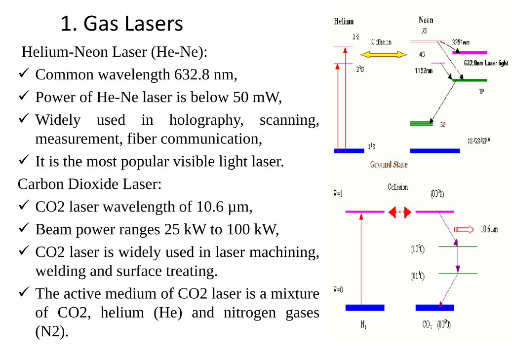
1. Gas LasersHelium-Neon Laser (He-Ne): Common wavelength 632.8 nm, Power of He-Ne laser is below 50 mW, Widely used in holography, scanning,
measurement, fiber communication, It is the most popular visible light laser.Carbon Dioxide Laser: CO2 laser wavelength of 10.6 µm, Beam power ranges 25 kW to 100 kW, CO2 laser is widely used in laser machining,
welding and surface treating. The active medium of CO2 laser is a mixture
of CO2, helium (He) and nitrogen gases(N2).
In solid state laser, ions are suspended in crystallinematrix to generate laser light.
• Ruby Cr3+ Al2O3:-wave length – 694.3 nm,Power 100 kW to 105 kW
• Nd3+ Glass:-Wave length – 1060 nm,Power 105 kW to 109 kW
• Nd3+ YAG:-Wave length – 1640 nm,Power 5 x 10⁵ kW,YAG (Y3Al5O12) Yttrium Aluminum Garnet,
Transferent and colorless
2. Solid State Lasers
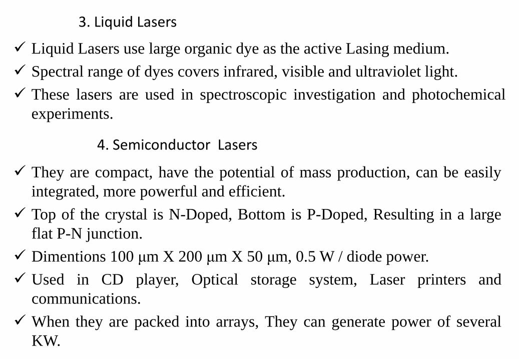
Liquid Lasers use large organic dye as the active Lasing medium. Spectral range of dyes covers infrared, visible and ultraviolet light. These lasers are used in spectroscopic investigation and photochemical
experiments.
3. Liquid Lasers
4. Semiconductor Lasers
They are compact, have the potential of mass production, can be easilyintegrated, more powerful and efficient.
Top of the crystal is N-Doped, Bottom is P-Doped, Resulting in a largeflat P-N junction.
Dimentions 100 μm X 200 μm X 50 μm, 0.5 W / diode power. Used in CD player, Optical storage system, Laser printers and
communications. When they are packed into arrays, They can generate power of several
KW.
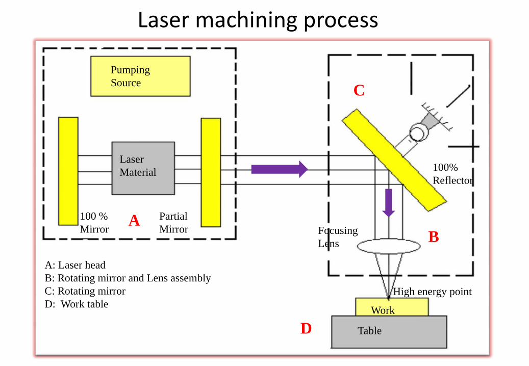
Laser machining process
Pumping Source
Laser Material
100 % Mirror
Partial MirrorA
C
B
D
100% Reflector
Focusing Lens
High energy point
Work
Table
A: Laser headB: Rotating mirror and Lens assemblyC: Rotating mirrorD: Work table
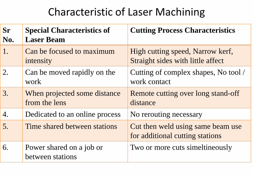
Characteristic of Laser MachiningSrNo.
Special Characteristics of Laser Beam
Cutting Process Characteristics
1. Can be focused to maximum intensity
High cutting speed, Narrow kerf, Straight sides with little affect
2. Can be moved rapidly on the work
Cutting of complex shapes, No tool / work contact
3. When projected some distance from the lens
Remote cutting over long stand-off distance
4. Dedicated to an online process No rerouting necessary5. Time shared between stations Cut then weld using same beam use
for additional cutting stations6. Power shared on a job or
between stationsTwo or more cuts simeltineously
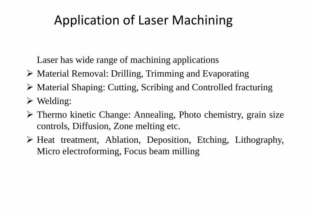
Application of Laser Machining
Laser has wide range of machining applications Material Removal: Drilling, Trimming and Evaporating Material Shaping: Cutting, Scribing and Controlled fracturing Welding: Thermo kinetic Change: Annealing, Photo chemistry, grain size
controls, Diffusion, Zone melting etc. Heat treatment, Ablation, Deposition, Etching, Lithography,
Micro electroforming, Focus beam milling
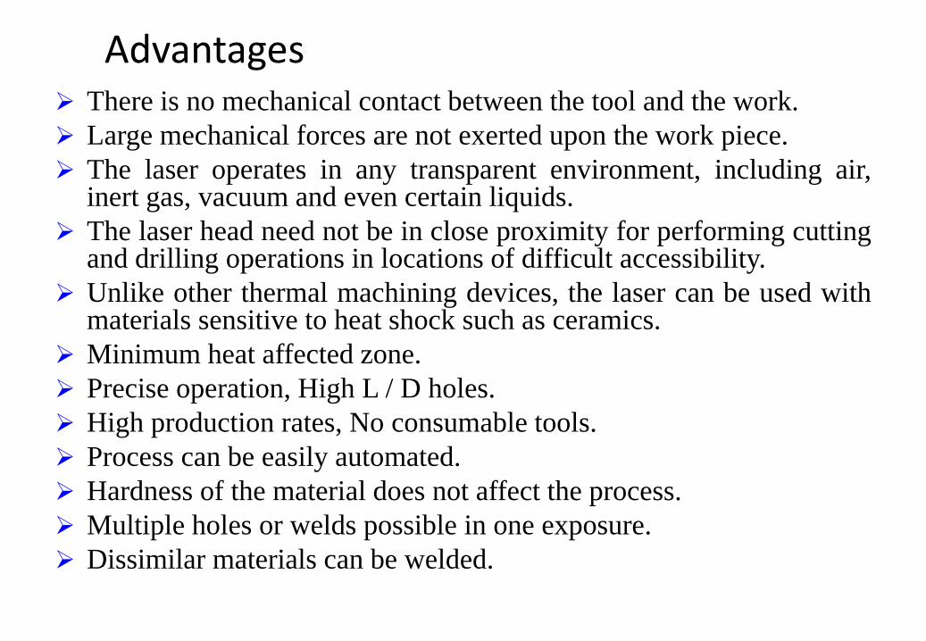
Advantages There is no mechanical contact between the tool and the work. Large mechanical forces are not exerted upon the work piece. The laser operates in any transparent environment, including air,
inert gas, vacuum and even certain liquids. The laser head need not be in close proximity for performing cutting
and drilling operations in locations of difficult accessibility. Unlike other thermal machining devices, the laser can be used with
materials sensitive to heat shock such as ceramics. Minimum heat affected zone. Precise operation, High L / D holes. High production rates, No consumable tools. Process can be easily automated. Hardness of the material does not affect the process. Multiple holes or welds possible in one exposure. Dissimilar materials can be welded.
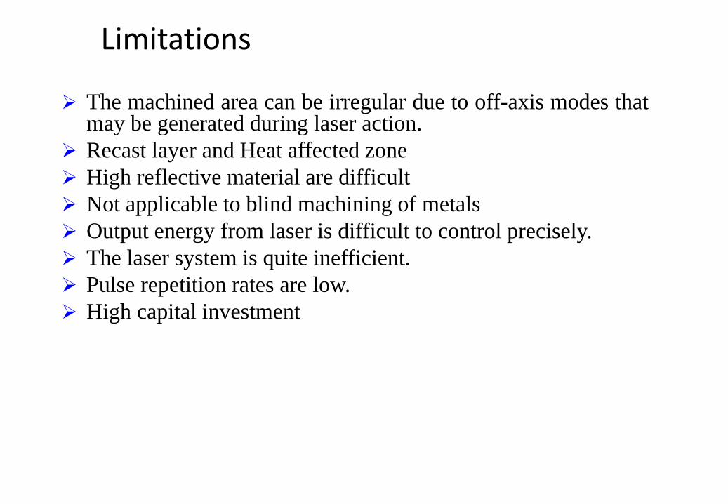
Limitations
The machined area can be irregular due to off-axis modes thatmay be generated during laser action.
Recast layer and Heat affected zone High reflective material are difficult Not applicable to blind machining of metals Output energy from laser is difficult to control precisely. The laser system is quite inefficient. Pulse repetition rates are low. High capital investment
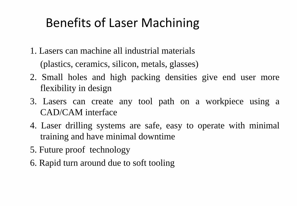
Benefits of Laser Machining
1. Lasers can machine all industrial materials(plastics, ceramics, silicon, metals, glasses)
2. Small holes and high packing densities give end user moreflexibility in design
3. Lasers can create any tool path on a workpiece using aCAD/CAM interface
4. Laser drilling systems are safe, easy to operate with minimaltraining and have minimal downtime
5. Future proof technology6. Rapid turn around due to soft tooling
Introduction:
Ultrasonic: A vibratory wave of a frequency above that of the upper frequencylimit of the human ear. The Ultrasonic waves are sound waves of frequencyhigher than 16 kHz/sec.
Ultrasonic waves can be generated using mechanical, electromagnetic andthermal energy sources.
They can be propagated in solids, liquids and gases and can travel at a highvelocity so that their wavelength is short in most media.
The electrical energy is converted into mechanical vibrations, and thatvibration is used to make material removal from some metals.
Ultrasonic Machining
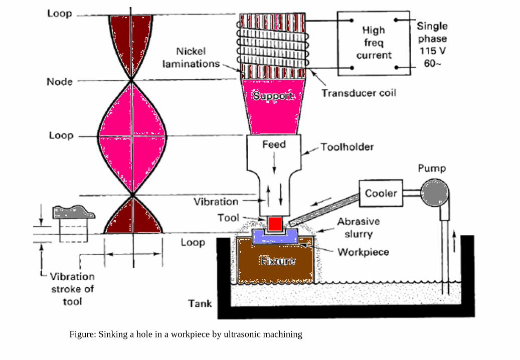
Figure: Sinking a hole in a workpiece by ultrasonic machining
Process principles:╠ USM: Material removal process used to erode cavities in hard work pieces by
using shaped tools, high-frequency mechanical motion and abrasive slurry.
╠ Because the process is non-chemical and non thermal, materials are not alteredeither chemically or metallurgically.
╠ Ultrasonic machining is able to effectively machine all materials harder thanHRc40, whether or not the materials are an electrical conductor or an insulator.
╠ The USM process begins with the conversion of low-frequency electrical energyto a high-frequency electrical signal, which is then fed to a transducer.
╠ The transducer is a device that converts the high frequency electrical signal to ahigh frequency linear mechanical motion.
╠ The transducer is a device that converts the high frequency electrical signal to ahigh frequency linear mechanical vibration motion (3 – 5 μ).
╠ The high frequency mechanical motion is transmitted to the tool via a mechanicalcoupler known as a tool holder. The tool vibrates in a direction parallel to the axisof the tool feed with in a few hundredths of a millimeter.
╠ Resonance is achieved when the frequency of vibration matches the naturalfrequency to generate a ultrasonic wave within the tool-tool holder assembly, thusresulting in maximum vibrational amplitude.
╠ The tool is shaped to desired cavity and positioned near, but not touching, thesurface of the work piece. The gap between the vibrating tool and work piece isflooded with abrasive slurry comprising water and small abrasive particles.
╠ Material removal occurs when the impact from the tool propels the abrasiveparticles across the cutting gap causing them to strike the work piece with a forceup to 1, 50,000 times their weight.
╠ Each down stroke of the tool can simultaneously accelerate thousands of abrasiveparticles; thus chips are removed from the work piece every second. That is whythe process is also known as ultrasonic impact grinding (UIG).
╠ As material is removed, Feed mechanism, continuously advances the tool intonewly formed cavity to maintain a constant gap between the tool and the workpiece.
╠ In USM MRR is low but the process remains economically because of its ability,with a single pass of the tool, to generate complex cavities in w/p that are toofragile to machine by another processes.
╠ In addition to its manufacturing capabilities, USM is also quite possibly the safestof all non traditional processes because it involves no high voltage, burning,cutting, chemicals or dangerous mechanical motions, In fact, USM cannot even cutskin because of the skin's ductility.
Equipments:
The machines for USM range from small table-top sized units to large-capacity machine tools.
The power of a USM machine can range from 40W to 2400W. The materialremoval rate is directly related to the power capability of the USM machine.
All USM machines share common subsystems regardless of the physical sizeor power. The most important subsystems are:
۞ Power supply۞ Transducer۞ Tool holder۞ Tool۞ Abrasives
• Power Supply:
The power supply used for USM is more accurately characterized as a highpower sine wave generator that offers user control over both the frequencyand power of the generated signal.
It converts low frequency (60Hz) electrical power to high frequency approx to(20 KHz) electrical power.
The electrical signal is then supplied to the transducer for conversion intomechanical motion.
• Transducer:A transducer is a device that converts electrical energy to mechanical motion.Two types of transducer used for USM, piezo-electric and magneto-strictive.
1) Piezo-Electric transducer:
╠ Some materials like quartz or Lead-Zirconate-Titanate will generate a smallelectric current when they compressed.
╠ In reverse, when an electric current is applied to one of these materials, thematerial increases minutely in size, when the current is removed the materialinstantly returns to its original shape.
╠ This characteristic is used to generate mechanical vibration in USM. Piezo electrictransducers, by nature exhibit an extremely high electro mechanical conversionefficiency (up to 96%), which eliminates the need for water cooling of thetransducers.
╠ These transducers are available with power capabilities up to 900W.
2) Magneto strictive transducer:
╠ Magneto strictive transducers are usually constructed from a laminatedstack of Nickel Alloy sheets which, when influenced by a strong magneticfield, will change length.
╠ Magneto-strictive transducers are rugged but have electro mechanicalconversion efficiencies ranging from only 20 to 35 %.
╠ The lower efficiency results in the need to water cool magneto strictivedevices to remove the waste heat.
╠ The magneto strictive transducers are available with power capabilitiesup to 2400 watts.

• Tool Holders:
╠ The function of the tool holder is to attach and hold the tool to the transducer.Additionally, the transducer also transmits the sonic energy to the tool, and insome applications, also amplifies the length of the stroke at the tool.
╠ With this capacity, the tool holder must be detachable, be constructed ofmaterials that have good acoustic properties, and be highly resistant to fatiguecracking.
╠ Tool Holders are attached to the transducer by means of a large, loose fittingscrew which has intentionally over size threads in the female portion andunder size threads in the male portion.
╠ If this screw junction were tight fitting, an ultrasonic weld would permanentlybond the tool holder to the transducer.
╠ Tool holders are available in two configurations: Non amplifying and amplifying.Non amplifying tool holders are cylindrical and result in the same strokeamplitude at the output end as at the input end. Amplifying tool holders have amodified cross section, and are designed to increase the amplitude of the toolstroke as much as 600%.Amplifying tool holders increase tool motion throughstretching and relaxation of the tool holder material.
╠ Because of the gain in tool stroke, amplifying tool holders are able to removematerial up to 10 times faster than the non amplifying types.
╠ The disadvantages of using amplifying tool holders include increased cost tofabricate, a reduction in surface finish quality, and the requirement of muchmore frequent tuning to maintain resonance.
• TOOLS
╠ To minimize tool wear tools should be constructed from relatively ductilematerials such as stainless steel, Brass, and Mild Steel. The harder the toolmaterial the faster its wear rate will be.
╠ Depending upon the abrasive used the work piece material, and the toolmaterial, work piece/tool wear ratios can range from 1:1 to 100:1.
╠ Both tools and tool holders should be free of scratches, nicks and heavymachining marks, because these produce stress risers and lead to early fatiguefailure.
╠ Because of the over cut that occurs with this process, allowances must be madeto use tools that are slightly smaller than the desired hole or cavity. For example,to allow for over-cut, the diameter of the tubing used to drill holes should beequal to the desired hole diameter - twice the abrasive particle size.
╠ The most desirable methods of attaching the tool to the tool holder are by silverbrazing. This eliminates the fatigue problems associated with mechanical screwattachment methods.
• Abrasives
╠ Abrasives are available in various particle sizes for USM. The criteria for selectionof an abrasive include hardness, usable life, cost and particle size.
╠ In order of hardness, Boron Carbide, Silicon Carbide, and Aluminum Oxide are themost commonly used abrasives. The abrasive used for an application should beharder than the material being machined; otherwise, the usable lifetime of theabrasive would be substantially shortened.
╠ Boron Carbide is selected when machining the hardest workpiece materials or thehighest material removal rates are desired. Although the cost is 5 to 10 timesgreater then the next hardest abrasive Silicon Carbide, the usable life of BoronCarbide is 200 machine-operating hours before cutting effectiveness is lost anddisposal is necessary.
╠ The combination of high removal rates and extended lifetime justify the highercost of Boron Carbide.
╠ The size of the abrasive particles influences the removal rate and surface finishobtained, abrasives are available in grit sizes ranging from 240 to 800. Thecoarser grit exhibit the highest removal rates, they also result in the roughestsurface finishes and are therefore used only for roughing operations.Conversely, 800 grit abrasives will result in fine surface finishes, but at a drasticreduction in the removal rate.
╠ The most popular abrasive size used, based on the above considerations is,320- grit Boron Carbide.
╠ The abrasive material is mixed with water to form the slurry. The mostcommon abrasive concentration is 50%by weight; however this can vary from30 to 60%.
╠ Once the abrasive has been selected and mixed with water, it is pumped to thetool work piece interface by recirculating pumps at rates up to 26.5 L/min.
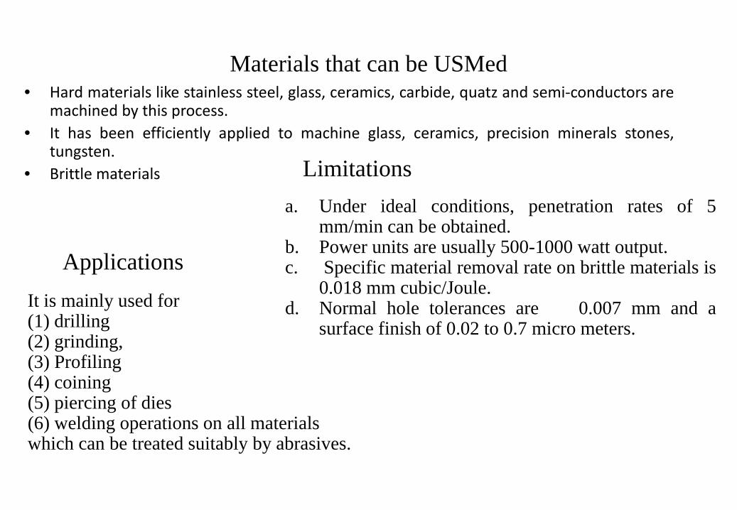
Materials that can be USMed• Hard materials like stainless steel, glass, ceramics, carbide, quatz and semi-conductors are
machined by this process.• It has been efficiently applied to machine glass, ceramics, precision minerals stones,
tungsten.• Brittle materials
ApplicationsIt is mainly used for(1) drilling(2) grinding,(3) Profiling(4) coining(5) piercing of dies(6) welding operations on all materialswhich can be treated suitably by abrasives.
Limitationsa. Under ideal conditions, penetration rates of 5
mm/min can be obtained.b. Power units are usually 500-1000 watt output.c. Specific material removal rate on brittle materials is
0.018 mm cubic/Joule.d. Normal hole tolerances are 0.007 mm and a
surface finish of 0.02 to 0.7 micro meters.
Advantages of USM
• Machining any materials regardless of their conductivity• USM apply to machining semi-conductor such as silicon, germanium etc.• USM is suitable to precise machining brittle material.• USM does not produce electric, thermal, chemical abnormal surface.• Can drill circular or non-circular holes in very hard materials • Less stress because of its non-thermal characteristics
Disadvantages of USM• USM has low material removal rate.• Tool wears fast in USM.• Machining area and depth is restraint in USM.
Introduction Process in which jet of water with high pressure and high velocity is
bombarded on the work piece to erode the material.
High pressure water jet has two properties, first its distraction power andsecond its application as a precision cutting tool.
High velocity water jet when directed at a target in such a way that, itsvelocity reduced to zero on striking the surface.
Practically most of the kinetic energy of jet is converted to very highpressure. Infect at the initial phase (with in first few mili-seconds) thetransient pressure reaches several times greater then the normal stagnationpressure.
This cause erosion if the local fluid pressure exceeds the strength of targetmaterial on in other words, the water jet will make a hole in the material ifthe pressure is high enough.
Water jet machining
Operating Principle of WJMThe equipments consists of three main subsystems:
1. Pump along with an intensifier to generate very high pressure (1-10 KBar)
2. Cutting unit consisting nozzle and work table movement
3. Filtration unit to remove the debris from water after use.
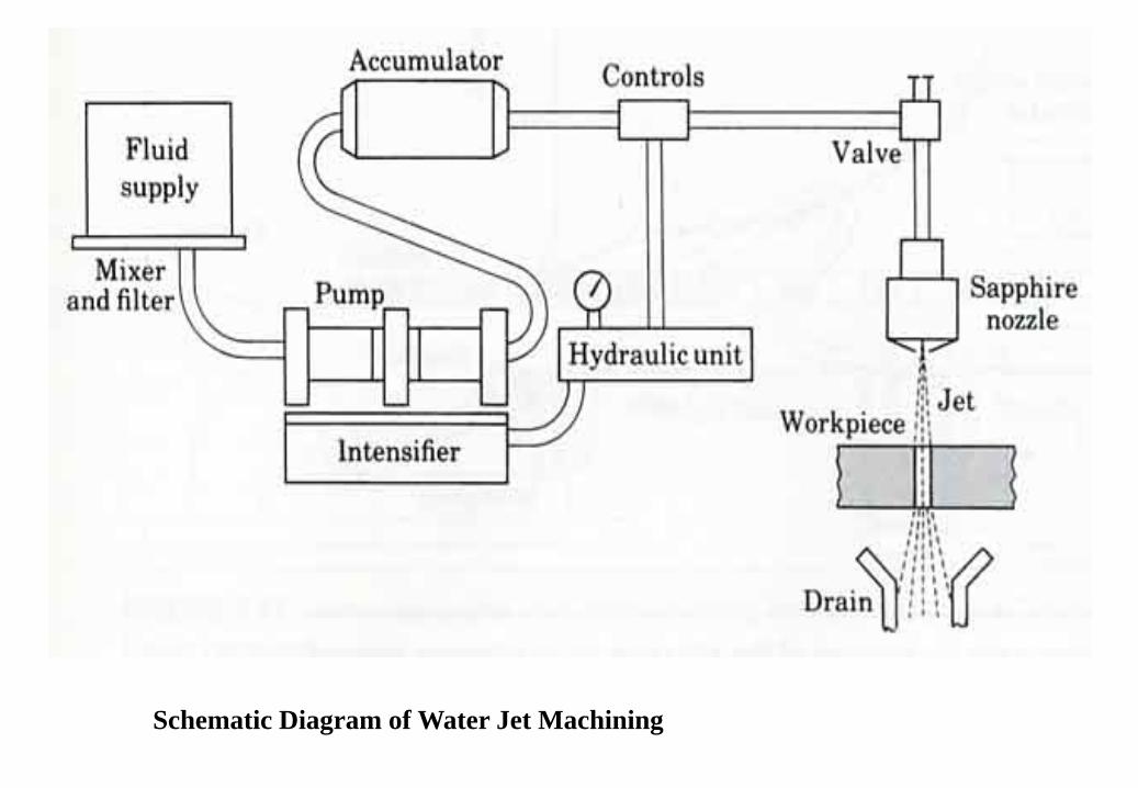
Schematic Diagram of Water Jet Machining
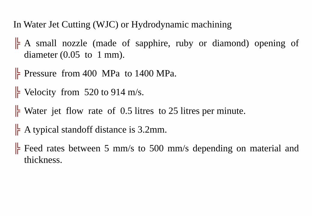
In Water Jet Cutting (WJC) or Hydrodynamic machining
╠ A small nozzle (made of sapphire, ruby or diamond) opening ofdiameter (0.05 to 1 mm).
╠ Pressure from 400 MPa to 1400 MPa.
╠ Velocity from 520 to 914 m/s.
╠ Water jet flow rate of 0.5 litres to 25 litres per minute.
╠ A typical standoff distance is 3.2mm.
╠ Feed rates between 5 mm/s to 500 mm/s depending on material andthickness.
╠ Used to cut narrow slits in flat stock such as plastic, textiles,composites, floor tile, carpet, leather, and cardboard
╠ The maximum thickness of cut, for most practical purposes is in theregion of 25 mm.
╠ Water jet machining is a very clean operation with no dust or odoursand very little noise, in fact the health and safety and environmentalimplications are almost negligible.
╠ To cut harder materials such as metal, abrasive particles such asGarnet or Alumina are added to the water prior to entering the cuttingzone. This is known as Abrasive Water Jet Machining.
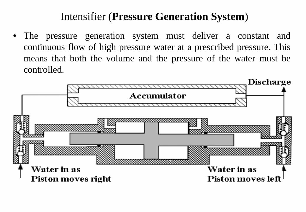
Intensifier (Pressure Generation System)
• The pressure generation system must deliver a constant andcontinuous flow of high pressure water at a prescribed pressure. Thismeans that both the volume and the pressure of the water must becontrolled.
Process Description:
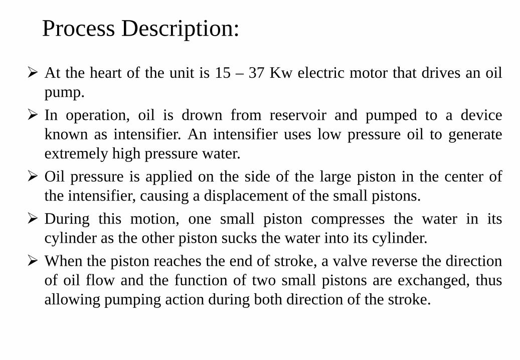
At the heart of the unit is 15 – 37 Kw electric motor that drives an oilpump.
In operation, oil is drown from reservoir and pumped to a deviceknown as intensifier. An intensifier uses low pressure oil to generateextremely high pressure water.
Oil pressure is applied on the side of the large piston in the center ofthe intensifier, causing a displacement of the small pistons.
During this motion, one small piston compresses the water in itscylinder as the other piston sucks the water into its cylinder.
When the piston reaches the end of stroke, a valve reverse the directionof oil flow and the function of two small pistons are exchanged, thusallowing pumping action during both direction of the stroke.
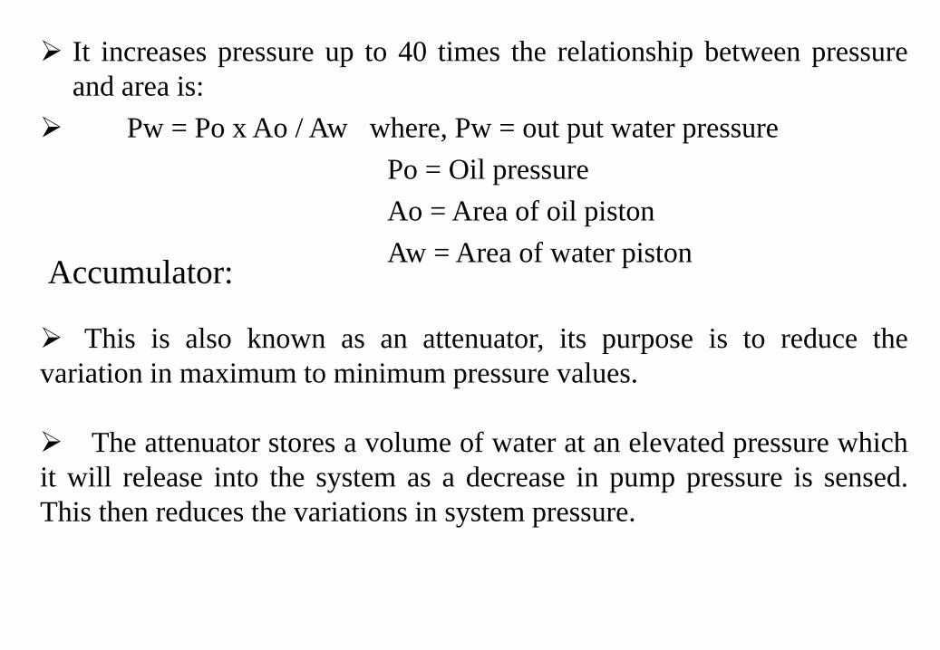
It increases pressure up to 40 times the relationship between pressureand area is:
Pw = Po x Ao / Aw where, Pw = out put water pressurePo = Oil pressureAo = Area of oil pistonAw = Area of water pistonAccumulator:
This is also known as an attenuator, its purpose is to reduce thevariation in maximum to minimum pressure values.
The attenuator stores a volume of water at an elevated pressure whichit will release into the system as a decrease in pump pressure is sensed.This then reduces the variations in system pressure.
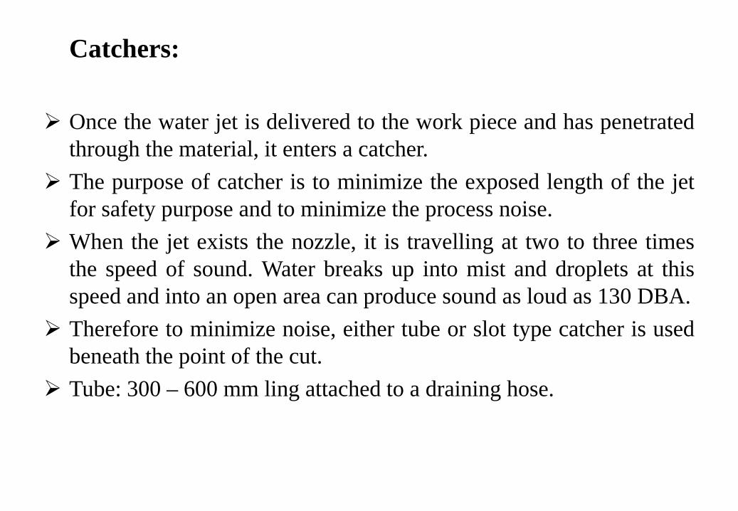
Catchers:
Once the water jet is delivered to the work piece and has penetratedthrough the material, it enters a catcher.
The purpose of catcher is to minimize the exposed length of the jetfor safety purpose and to minimize the process noise.
When the jet exists the nozzle, it is travelling at two to three timesthe speed of sound. Water breaks up into mist and droplets at thisspeed and into an open area can produce sound as loud as 130 DBA.
Therefore to minimize noise, either tube or slot type catcher is usedbeneath the point of the cut.
Tube: 300 – 600 mm ling attached to a draining hose.
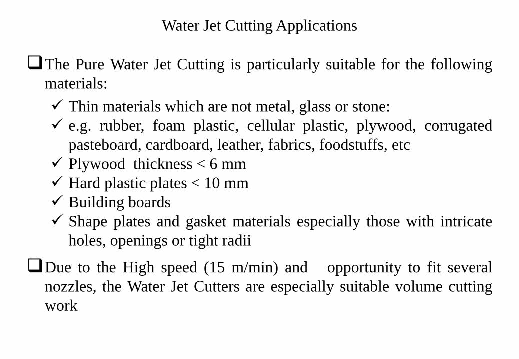
Water Jet Cutting Applications
The Pure Water Jet Cutting is particularly suitable for the followingmaterials: Thin materials which are not metal, glass or stone: e.g. rubber, foam plastic, cellular plastic, plywood, corrugated
pasteboard, cardboard, leather, fabrics, foodstuffs, etc Plywood thickness < 6 mm Hard plastic plates < 10 mm Building boards Shape plates and gasket materials especially those with intricate
holes, openings or tight radii
Due to the High speed (15 m/min) and opportunity to fit severalnozzles, the Water Jet Cutters are especially suitable volume cuttingwork
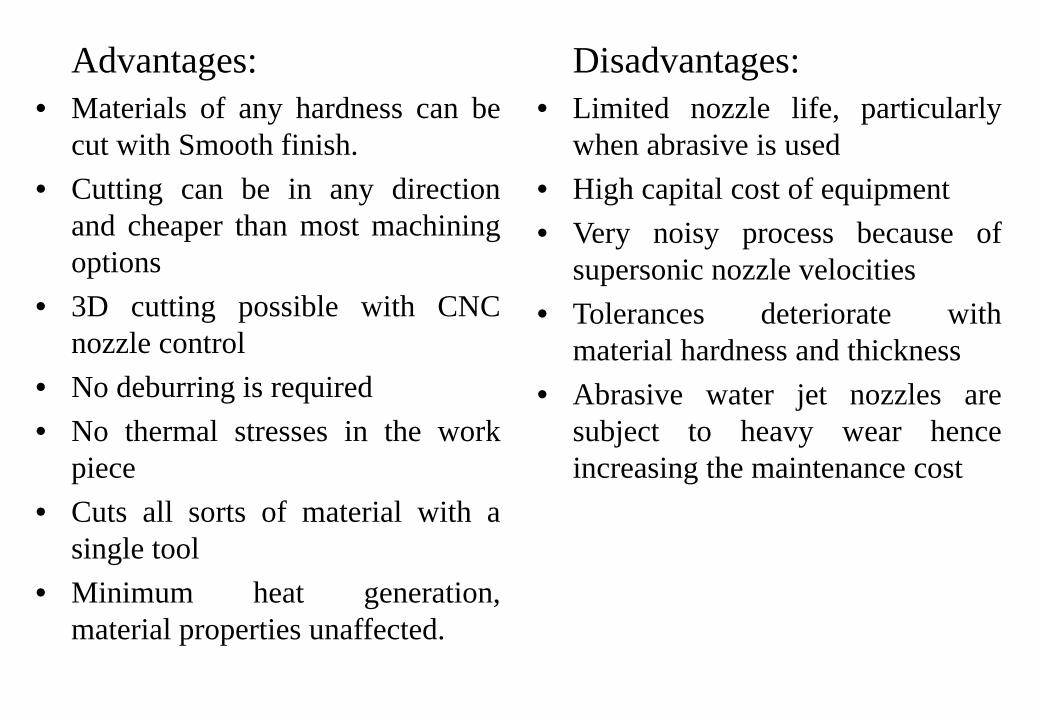
Advantages:• Materials of any hardness can be
cut with Smooth finish.• Cutting can be in any direction
and cheaper than most machiningoptions
• 3D cutting possible with CNCnozzle control
• No deburring is required• No thermal stresses in the work
piece• Cuts all sorts of material with a
single tool• Minimum heat generation,
material properties unaffected.
Disadvantages:• Limited nozzle life, particularly
when abrasive is used• High capital cost of equipment• Very noisy process because of
supersonic nozzle velocities• Tolerances deteriorate with
material hardness and thickness• Abrasive water jet nozzles are
subject to heavy wear henceincreasing the maintenance cost
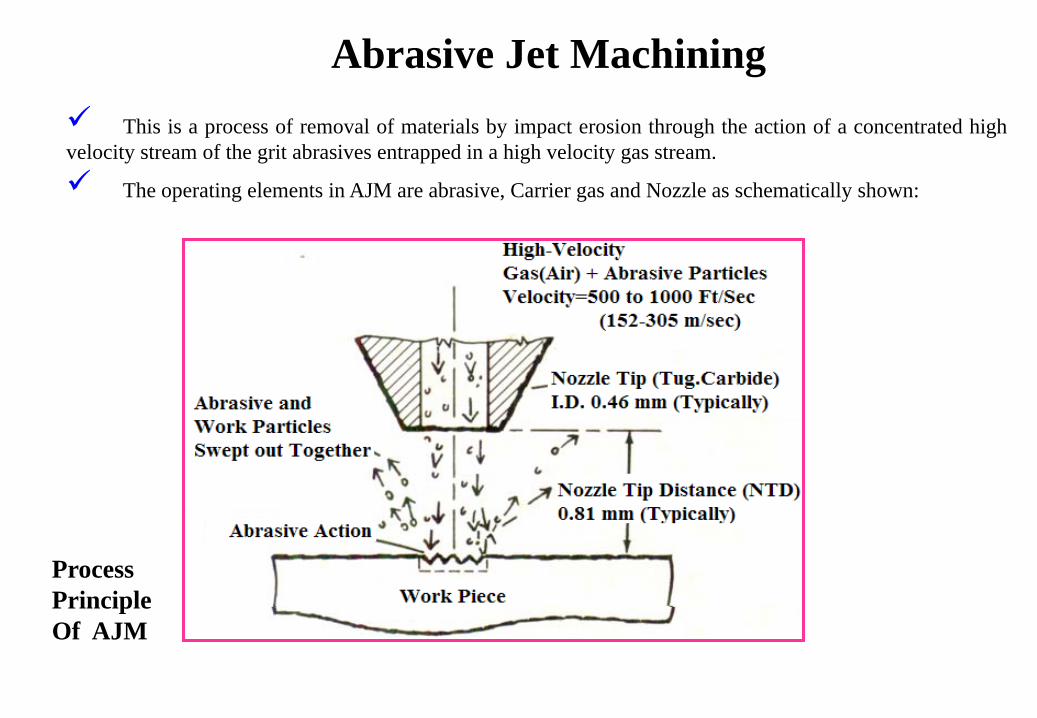
Abrasive Jet Machining This is a process of removal of materials by impact erosion through the action of a concentrated highvelocity stream of the grit abrasives entrapped in a high velocity gas stream.
The operating elements in AJM are abrasive, Carrier gas and Nozzle as schematically shown:
Process PrincipleOf AJM
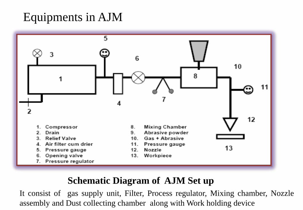
Equipments in AJM
Schematic Diagram of AJM Set upIt consist of gas supply unit, Filter, Process regulator, Mixing chamber, Nozzleassembly and Dust collecting chamber along with Work holding device
It consists of four major subsystems1) Gas propulsion system2) Metering System3) Delivery system4) Abrasive collection system1) Gas propulsion system:
This subsystem provides steady supply of clean and dry gas used to propel abrasiveparticles. Filters used to avoid water or oil contamination from the compressed air.Common gases are N2, CO2 but never O2 because of chances of fire hazard.
2/3) Metering and Delivery System:This subsystem is use to inject uniform and adjustable flow of abrasive particlesinto the gas stream. This is to be done by powder hopper that feeds into a vibratingchamber which in turn cause the powder to be metered uniformly into jet stream.Powder flow rate is directly adjustable by varying the amplitude of the vibration.
4) Abrasive collection system:This subsystem use to maintain the operators exposer to dust with in permissiblelimits. A vacuum dust collector is used to draw the dust particles from the exhaustchamber, if the toxic materials are being abraded.
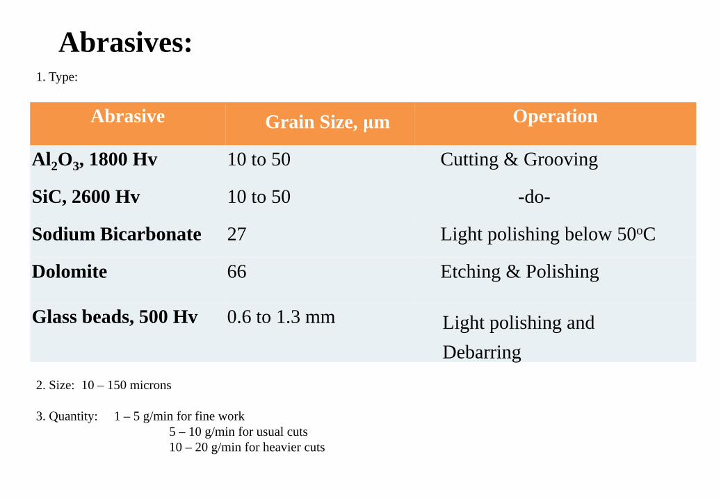
Abrasives:
Abrasive Grain Size, μm Operation
Al2O3, 1800 Hv 10 to 50 Cutting & Grooving
SiC, 2600 Hv 10 to 50 -do-
Sodium Bicarbonate 27 Light polishing below 50oC
Dolomite 66 Etching & Polishing
Glass beads, 500 Hv 0.6 to 1.3 mm Light polishing and Debarring
1. Type:
2. Size: 10 – 150 microns
3. Quantity: 1 – 5 g/min for fine work5 – 10 g/min for usual cuts10 – 20 g/min for heavier cuts
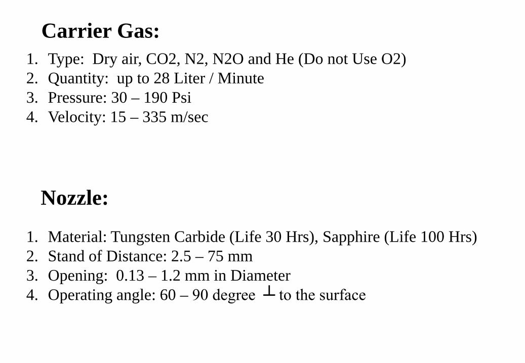
Carrier Gas:1. Type: Dry air, CO2, N2, N2O and He (Do not Use O2)2. Quantity: up to 28 Liter / Minute3. Pressure: 30 – 190 Psi4. Velocity: 15 – 335 m/sec
1. Material: Tungsten Carbide (Life 30 Hrs), Sapphire (Life 100 Hrs)2. Stand of Distance: 2.5 – 75 mm3. Opening: 0.13 – 1.2 mm in Diameter4. Operating angle: 60 – 90 degree ┴ to the surface
Nozzle:
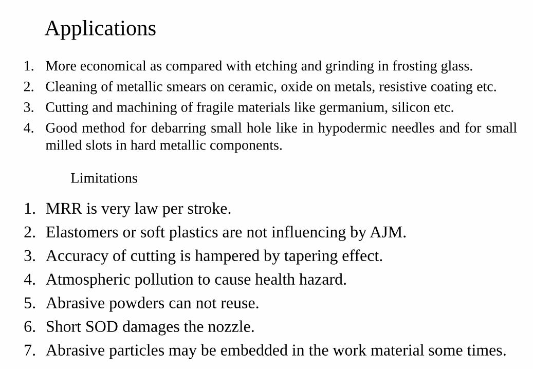
Applications 1. More economical as compared with etching and grinding in frosting glass.2. Cleaning of metallic smears on ceramic, oxide on metals, resistive coating etc.3. Cutting and machining of fragile materials like germanium, silicon etc.4. Good method for debarring small hole like in hypodermic needles and for small
milled slots in hard metallic components.
Limitations
1. MRR is very law per stroke.2. Elastomers or soft plastics are not influencing by AJM.3. Accuracy of cutting is hampered by tapering effect.4. Atmospheric pollution to cause health hazard.5. Abrasive powders can not reuse.6. Short SOD damages the nozzle.7. Abrasive particles may be embedded in the work material some times.
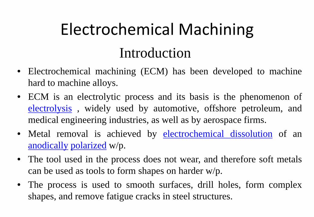
Introduction• Electrochemical machining (ECM) has been developed to machine
hard to machine alloys.• ECM is an electrolytic process and its basis is the phenomenon of
electrolysis , widely used by automotive, offshore petroleum, andmedical engineering industries, as well as by aerospace firms.
• Metal removal is achieved by electrochemical dissolution of ananodically polarized w/p.
• The tool used in the process does not wear, and therefore soft metalscan be used as tools to form shapes on harder w/p.
• The process is used to smooth surfaces, drill holes, form complexshapes, and remove fatigue cracks in steel structures.
Electrochemical Machining
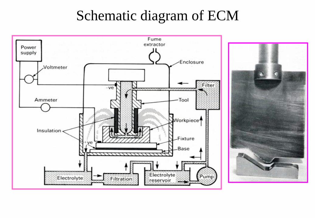
Schematic diagram of ECM
Working principle of ECM╠ In ECM, w/p and tool are the anode and cathode of an electrolytic cell,
and a constant voltage difference is applied across them.╠ A electrolyte is pumped at a rate 3 to 30 liter /second, through the gap
to remove the products of machining.╠ As machining proceeds toward the anode, the gap width along the
electrode length will gradually tend to a steady-state value.╠ With this working principles of ECM, its advantages through
machining processes:1. the rate of metal machining does not depend on the hardness of
the material,2. complicated shapes can be machined on hard metals,3. there is no tool wear.
ECM characteristics
1.Mechanics of material removal - electrolysis
2.Medium - conducting electrolyte
3.Tool material - Cu, brass, steel
4.Material/tool wear - infinite
5.Gap - 50 to 300 μm
6.Maximum MRR - 15*103 mm3/min
7.Specific power consumption - 7W/mm3/min
8. Critical parameters - voltage, current, feed rate, electrolyte,electrolyte conductivity
9. Materials application - all conducting metals and alloys10. Shape application - blind complex cavities, curved surfaces,
through cutting, large through cavities.11. Limitations - high specific energy consumption (about 150
times that required for conventional processes), not applicablewith electrically non-conducting materials and jobs with verysmall dimensions, expensive machines.
12. Surface finishes down to 25 μ.
Rates of machining• Material removal rate is proportional to current passed through the
electrolyte and the time for that operation.
• Other factors influence on MRR are electrolyte type, rate of electrolyteflow, and process conditions.
• For example
current efficiency decreases when current density is increased.
If flow rates kept too low, current efficiency of ECMed metal isreduced.
Insufficient flow not allow the debris to flush from the gap.
83
Surface finish• Quality of surface finish depends on type of electrolytes used in
process. e.g. NaCl tends to produce matte finish with steels and nickelalloys.
• Sometimes formation of oxide film on w/p hinders efficient ECM andleads to poor surface finish.
• Occasionally, ECMed metals have a pitted (Honeycombed) surfacewhile the remaining area is polished or matte.
• Process variables also affect surface finish. For example, as the currentdensity is raised, the finish becomes smoother on w/p.
• A similar effect is achieved when the electrolyte velocity is increased.
84
Accuracy and dimensional control• In hole drilling, high current densities occur between the leading
edge of the drilling tool and the w/p.
• In the side gap there is no direct movement between the tool andw/p surface, so the gap widens and the current densities are lower.
• Thus the over cut occurs in the side gap.
85
Design of ECM shaping are usually concerned with three distinctproblems:
The design of the cathode tool shape needed to produce a requiredprofile geometry of the anode w/p.
For a given cathode tool shape, prediction of the resultant anode w/pgeometry, for example, hole drilling by ECM.
Specification of the shape of the anode w/p, as machining proceedsand for estimation of the machining times as the shape developmentprovides useful information about the process.
86
Advantages of ECM
Electrochemical Machining has many advantages when compared toconventional machining.
The components are not subject to either thermal or mechanicalstress
There is no tool wear during Electrochemical machining Non-rigid and open work pieces can be machined easily as there is
no contact between the tool and w/p Complex geometrical shapes can be machined repeatedly and
accurately
87
Electron Beam Machining
Introduction• In electron beam machining a powerful stream of electrons is
directed at a part. This bombardment with electrons causes the material to locally heat up and vaporize.
• Electrons are accelerated with voltages of approx. 150,000V to create velocities over 200,000 km/sec. This produces velocities over 50% to 80% the speed of light.
• This beam of fast moving electrons can be focused to 10 to 200 micro m and a density of 6500 GW/mm2. Good for narrow holes and slots. e.g. a hole in a sheet 1.25 mm thick up to 125 micro m diameter can be cut almost instantly with a taper of 2 to 4 degrees
• Electron beam machining is used for drilling and cutting, metals, non-metals, ceramics, and composite materials.
• Electron beam machining is quite similar to laser-beam machining and the major difference between them is EBM requires a vacuum chamber which limiting the size of a part to be machined.
• In a business where time and accuracy are absolutely critical, electron beam machining can be the perfect solution to many problems.
• Typical uses for electron-beam machining are:( Drilling ( Cutting( Welding ( Annealing( Metal removal
An electron beam machine works in much the same way as a cathode ray tube in a television.
1. A cathode section generates an electron beam. 2. An anode section accelerates the beam. 3. The lens system converges and deflects the electron beam to
the desired position.
Working of Electron beam machining
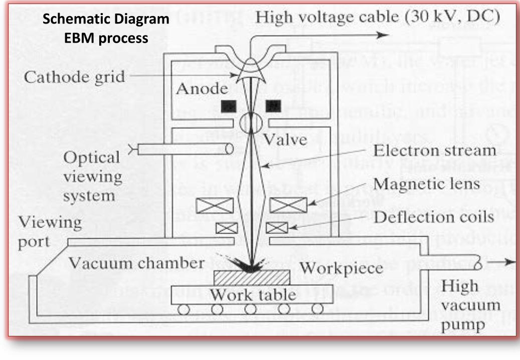
Schematic Diagram EBM process
• In electron beam machining process, first a stream of electrons is started by a voltage differential the cathode.
• The concave shape of the cathode grid concentrates the stream through the anode. Much like the way a concave mirror focuses a light beam from a flashlight.
• The anode applies a potential field that accelerates the electrons. This stream of electrons is then forced through a valve in the electron beam machine.
• The valve is used for the purpose of controlling the beam and the duration of a machining process.
• If the impulse of the electron beam is too great, part will over heat and potentially destroy the machined piece by material cold-working or tempering.
• The beam is focused onto the surface of the work material by a series of electromagnetic lens and deflector coils.
• The entire process occurs in a vacuum chamber, reason is that air molecules can adversely interact with the beam of electrons.
• A collision between an electron and a air molecule causes the electron to curve off, phenomenon is illustrated in figures (Electron Beam in Vacuum and Air).
• Stream of electrons is directed to w/p; on impact, the kinetic energy of the electrons is converted into thermal energy that melts and vaporizes the material to be removed, forming cuts.
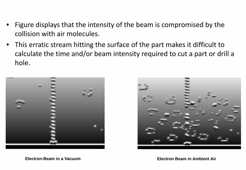
• Figure displays that the intensity of the beam is compromised by the collision with air molecules.
• This erratic stream hitting the surface of the part makes it difficult to calculate the time and/or beam intensity required to cut a part or drill a hole.
Electron-Beam in a Vacuum Electron Beam in Ambient Air
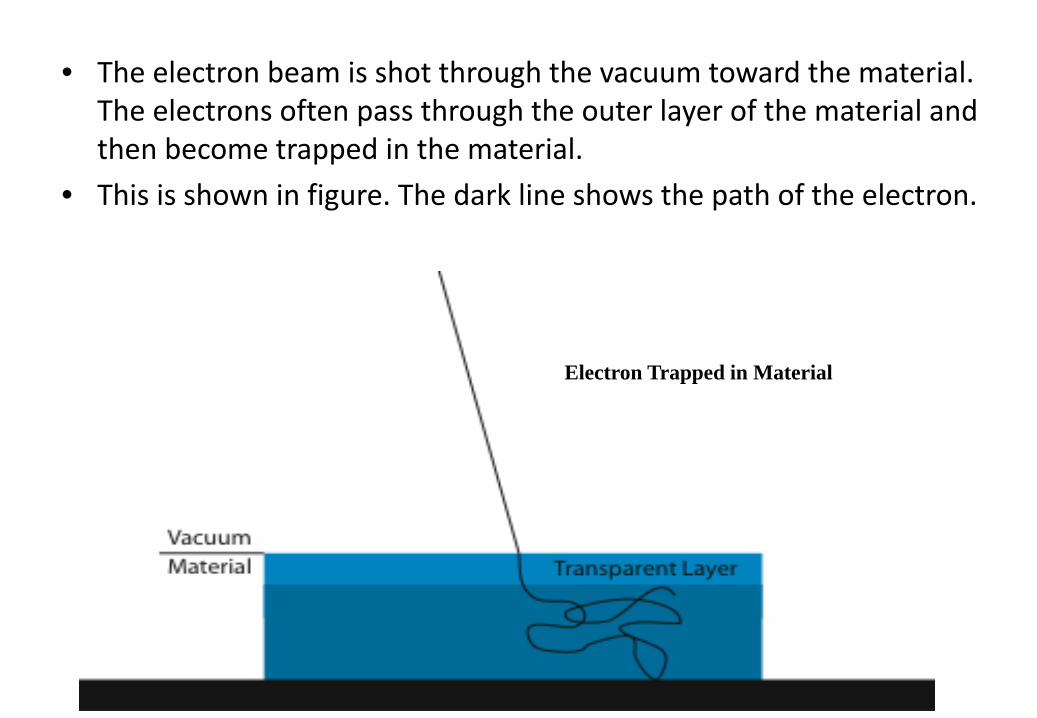
• The electron beam is shot through the vacuum toward the material. The electrons often pass through the outer layer of the material and then become trapped in the material.
• This is shown in figure. The dark line shows the path of the electron.
Electron Trapped in Material
Uses of E-Beam Machining
• Drilling small holes:The electron-beam is used to vaporize material from a piece. Hole
on the order of a few nanometers can be drilled. Further E-beam drilling can machine a desired hole taper.
• Cutting:The electron-beam basically drill a continuous series of hole. The
E-beam produces very crisp and accurate cuts. Additionally the E-beam can be used to cut small slots.
• Welding:The electron-beam is used to join to pieces of metal by raising
the temperature of two pieces to the melting temperature.• Annealing:
The electron-beam is used to raise the temperature of a material and relax any residual stresses. This is often done in conjunction with one of the other processes to reduce the number of steps needed to complete a part.
• EBM equipment is commonly used by the electronics industry to aid in the etching of circuits in microprocessors.
Pros• Fast: • In a blink of the eye a tiny hole can be drilled into all materials. • The beam of electrons move at a very high velocity.• Accommodate small batches: • Current trends in manufacturing are for a lean process. In other words,
the fewer parts that have to be kept in the warehouse, the better produce on demand machining.
• Single step process: • In EBM, same tool can be used to anneal and/or weld it at the same
time, the tool can be used to reduce the steps necessary to produce a finished part.
• Reduced steps equals both cost and time savings.• Accurate and can be used on nearly all materials
Cons• Need of a vacuum chamber limits part size• Expensive if accuracy unnecessary• Laser beam machining often just as effective• High specific energy consumption and
expensive machine costs