un50eh5000fxza fast track cr62612...un50eh5000fxza fast track troubleshooting manual 1111 d1 d1 d1...
TRANSCRIPT
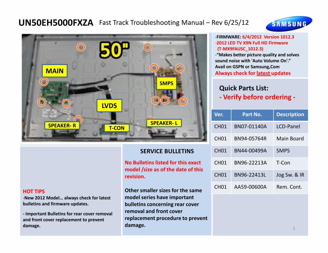
UN50EH5000FXZA
-FIRMWARE: 6/4/2012 Version 1012.3
-2012 LED TV X9N Full HD Firmware
(T-MX9FAUSC_1012.3)
-“Makes better picture quality and solves
sound noise with 'Auto Volume On'.”
Avail on GSPN or Samsung,Com
Always check for latest updates
Fast Track Troubleshooting Manual – Rev 6/25/12
Quick Parts List:
- Verify before ordering -
MAIN
T-CON
LVDS
SMPS
SPEAKER- LSPEAKER- R
Ver. Part No. Description
CH01 BN07-01140A LCD-Panel
SERVICE BULLETINS
No Bulletins listed for this exact
model /size as of the date of this
revision.
Other smaller sizes for the same
model series have important
bulletins concerning rear cover
removal and front cover
replacement procedure to prevent
damage.
HOT TIPS-New 2012 Model… always check for latest
bulletins and firmware updates.
- Important Bulletins for rear cover removal
and front cover replacement to prevent
damage.1
T-CONSPEAKER- R CH01 BN07-01140A LCD-Panel
CH01 BN94-05764R Main Board
CH01 BN44-00499A SMPS
CH01 BN96-22213A T-Con
CH01 BN96-22413L Jog Sw. & IR
CH01 AA59-00600A Rem. Cont.
Fast Track Troubleshooting ManualUN50EH5000FXZA
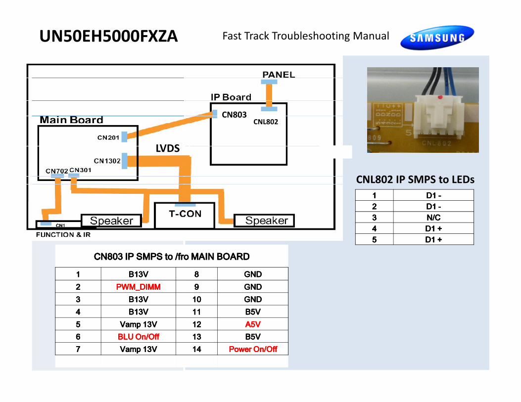
1111 D1 D1 D1 D1 ----2222 D1 D1 D1 D1 ----
CNL802 IP SMPS to LEDs
LVDS
CNL802CN803
CN803 IP SMPS to /fro MAIN BOARDCN803 IP SMPS to /fro MAIN BOARDCN803 IP SMPS to /fro MAIN BOARDCN803 IP SMPS to /fro MAIN BOARD1111 B13VB13VB13VB13V 8888 GNDGNDGNDGND2222 PWM_DIMMPWM_DIMMPWM_DIMMPWM_DIMM 9999 GNDGNDGNDGND3333 B13VB13VB13VB13V 10101010 GNDGNDGNDGND4444 B13VB13VB13VB13V 11111111 B5VB5VB5VB5V5555 Vamp 13VVamp 13VVamp 13VVamp 13V 12121212 A5VA5VA5VA5V6666 BLU On/OffBLU On/OffBLU On/OffBLU On/Off 13131313 B5VB5VB5VB5V7777 Vamp 13VVamp 13VVamp 13VVamp 13V 14141414 Power On/OffPower On/OffPower On/OffPower On/Off
2222 D1 D1 D1 D1 ----3333 N/CN/CN/CN/C4444 D1 +D1 +D1 +D1 +5555 D1 +D1 +D1 +D1 +

UN**EH TV Start Up Sequence
Sequence Location DC Voltage
1. 5V STBY to
Main Board
CN803-12
(A5V)
5V
2. Power On/Off
From Main Board
CN803-14
(Power On/Off)Power On/Off)Power On/Off)Power On/Off)0V-3.5V
3. Low Volts On to
Main Board with Booting
Melody (X9 MStar)
CN803-1,3,5,7 (B13V)
CN803- 11,13 (B5) 13V
5V
4. Back Light On/Off CN803-6) 0V – 4.9V 5
MAIN
SMPS
4. Back Light On/Off
From Main Board
CN803-6)
BLU On/Off
0V – 4.9V 5
Sec Dly
5. Back Light Dim Control
from Main Board “0 to 20”
Backlight
CN803 - 2
(PWM_DIMM)
effective DC Voltage is
max when backlight
max
0.5V – 4.0V
(effective)
Dark to
Bright
6. Dim Control Out from IP
SMPS to LEDs D1 – is max
voltage when backlight is min
CNL802-1 & 2 (D1 -)
C NL802-4 & 5 (D1+)
D1 + stays constant DC
voltage.
1.3V-32.8V
110.8V

� Standby A3.3V
on Function
Connector, Pin
3.
� All Pins should
read 3.3V
before
commands.
Function Control Troubleshooting
4
� Press, at Key 1,
Pin 6. 3.3V to
0.0V DC
� Left, Right, Up,
Down at
Key 2, Pin 7.
Check specific
voltages on
chart.
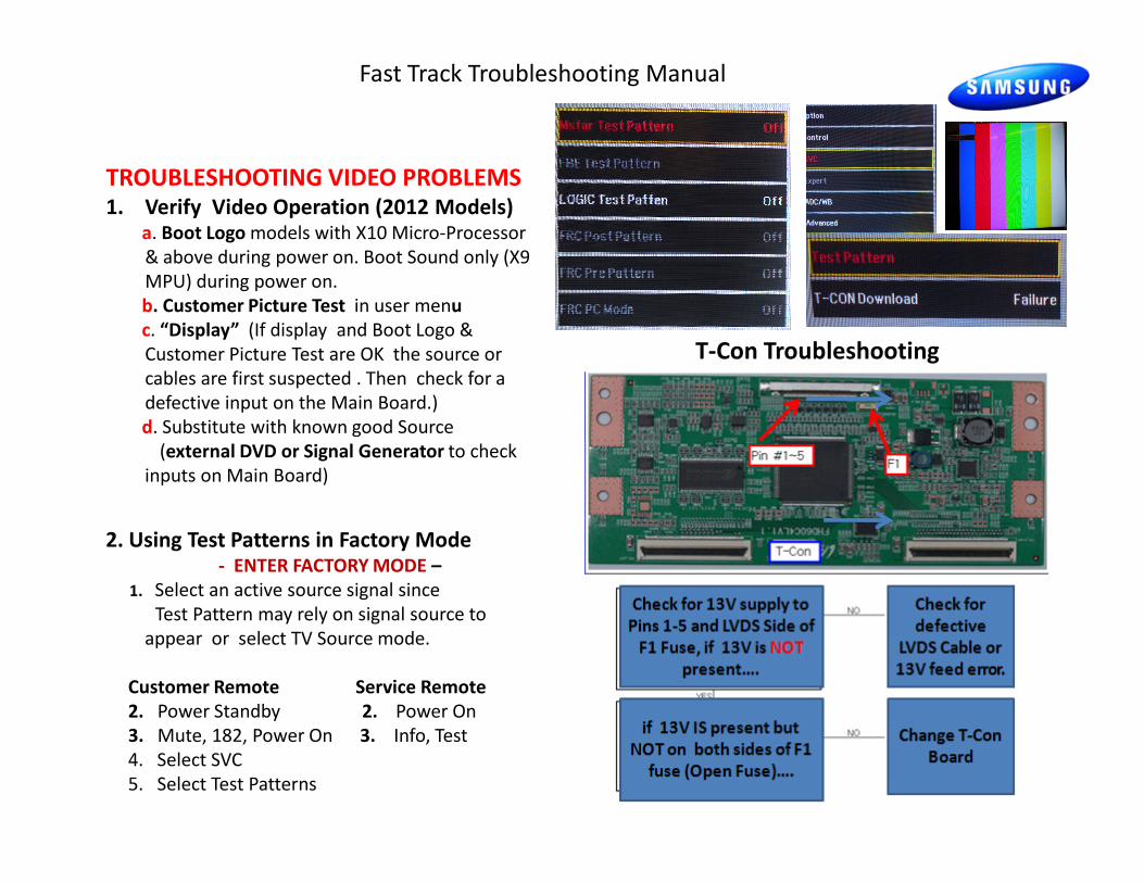
TROUBLESHOOTING VIDEO PROBLEMS 1. Verify Video Operation (2012 Models)
a. Boot Logo models with X10 Micro-Processor
& above during power on. Boot Sound only (X9
MPU) during power on.
b. Customer Picture Test in user menu
c. “Display” (If display and Boot Logo &
Customer Picture Test are OK the source or
cables are first suspected . Then check for a
defective input on the Main Board.)
d. Substitute with known good Source
(external DVD or Signal Generator to check
Fast Track Troubleshooting Manual
T-Con Troubleshooting
5
(external DVD or Signal Generator to check
inputs on Main Board)
2. Using Test Patterns in Factory Mode - ENTER FACTORY MODE –
1. Select an active source signal since
Test Pattern may rely on signal source to
appear or select TV Source mode.
Customer Remote Service Remote
2. Power Standby 2. Power On
3. Mute, 182, Power On 3. Info, Test
4. Select SVC
5. Select Test Patterns

ON SCREEN FAILURE EXAMPLES: ALIGNMENTS:Fast Track Troubleshooting Manual
1. Check/Set Option Bytes: in Factory Mode
(Must be performed after replacing Main Board. )
Green lines or a green screen defective main board , LVDS , or T-CON.
If Picture & Display errors
Defective Main Board, LVDS,
or T-CON
2. Check/Perform latest Firmware
Upgrade for all repairs.
Standard Remote
1. Power OFF the TV
2. Press MUTE, 1 8 2, then POWER
Factory remote
1. Power the TV ON
2. Press INFO then FACTORY
6
SPECIAL NOTES:
Inform customer of reset of all
Settings if Main Board is replaced.
Pixelization can be caused by the main board
but is more commonly a source error
Upgrade for all repairs.
3. Perform reset in Service Mode
if Main board is replaced.
Vertical or Horizontal Lines :Defective
Panel likely but also T-CON, LVDS, or Main
Board. Use Test Patterns in Factory Service
Mode to determine error)
Option Bytes settings for UN50EH5000
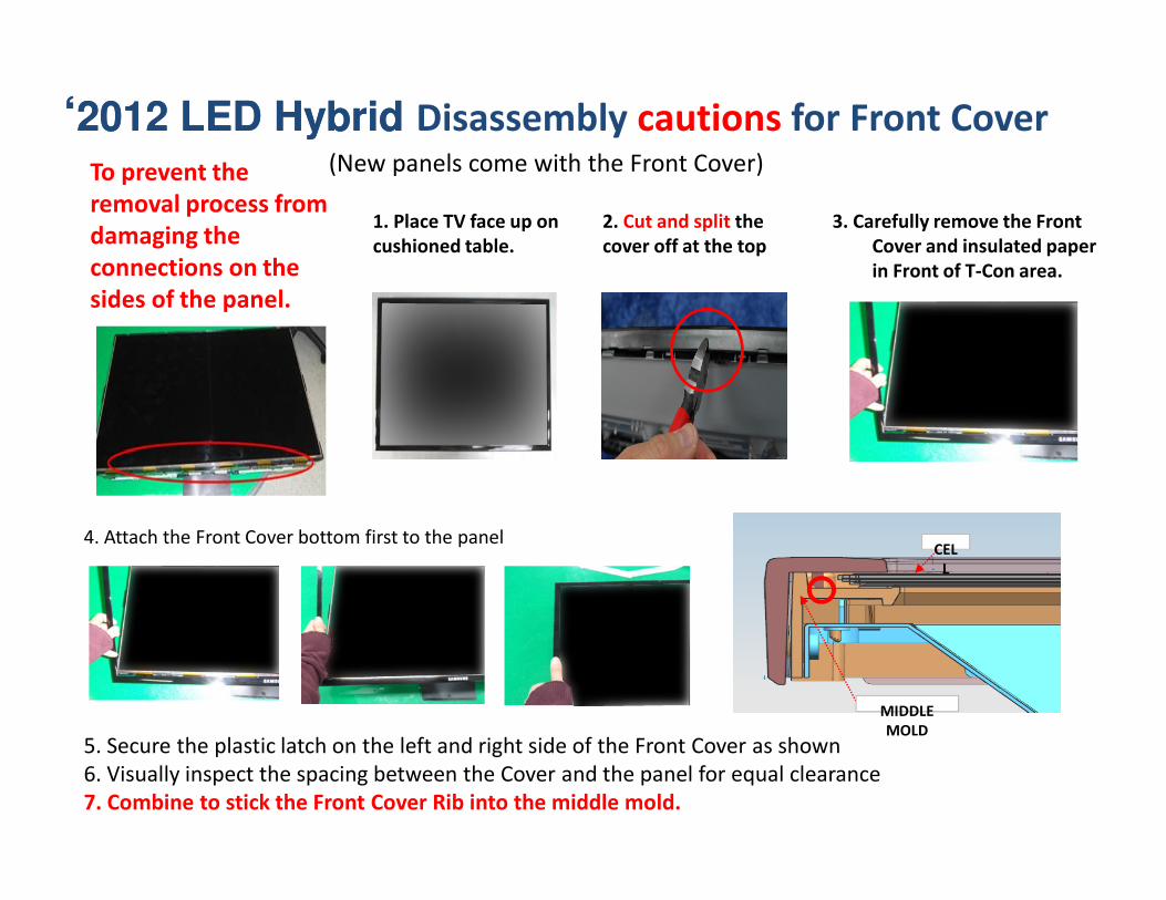
‘‘2012 LED Hybrid 2012 LED Hybrid Disassembly cautions for Front Cover
To prevent the
removal process from
damaging the
connections on the
sides of the panel.
2. Cut and split the
cover off at the top
(New panels come with the Front Cover)
1. Place TV face up on
cushioned table.
3. Carefully remove the Front
Cover and insulated paper
in Front of T-Con area.
4. Attach the Front Cover bottom first to the panel
5. Secure the plastic latch on the left and right side of the Front Cover as shown
6. Visually inspect the spacing between the Cover and the panel for equal clearance
7. Combine to stick the Front Cover Rib into the middle mold.
MIDDLE
MOLD
CEL
L