un in i im n iii i i if! ni · in i im n iii i i if! ni ... a rectangular waveguide with transverse...
TRANSCRIPT
AFCRL-63-139
AD-A285 480uN IN I N IM III I I If! NI
LEAKY WAVE RADIATION FROM A PERIODICALL
SLOTTED WAVEGUIDE
by
Jean-Paul Renault
Research Report PIBMRI- 1151-63for
Air Force Cambridge Research LaboratoriesOffice of Aerospace Research
United States Air ForceBedford, Mass.
Contract No. AF-19(604)-7499Project 4600, Task460004
May 8, 1963
L
-. °
94-24355 . /I N lHlllllltflllllllillIE WH~lill > •'" EMRI1
POLYTECHNIC INSTITUTE OF BROOKLYN
IJ1CROWAVE RESEARCH INSTITUTEELECTROPHYSICS DEPARTMENT

(
"Requests for additional copies by Agencies of the Departmentof Defense, their contractors, and other Government Agenciesshould be directed to the:
DEFENSE DOCUMENTATION CENTER (DDC)Cameron StationAlexandria, Virginia
Department of Defense contractors must be established for DDCservices or have their 'need-to-know' certified by the cognizantmilitary agency of their project or contract.
"All other persons and organizations should apply to the:
U.S. DEPARTMENT OF COMMERCEOFFICE OF TECHNICAL SERVICESWASHINGTON 25, D.C."
I 0 II
"AFCRL-63-139 Research Report No. PIBMRI-1151-63
LEAKY WAVE RADIATION FROM A PERIODICALLY
SLOTTED WAVEGUIDE
by
Jean-Paul Renault
Polytechnic Institute of BrooklynMicrowave Research Institute
55 Johnson StreetBrooklyn 1, New York
Research Report PIBMRI-1151-63Contract No. AF- 19(604)-7499
Project 4600Task 460004
May 8, 1963
Title PageAcknowledgmentAbstractTable of Contents16 pages of textDistribution
Jeffn-Paul Renaulte search Fellow
Approved by:KJAATr. =.arlin
Head, Electrophysks Dept.
forAir Force Cambridge Research Laboratories
Office of Aerospace ResearchUnited States Air Force
Bedford, Mass.
ACKNOWLEDGMENT
The author is pleased to acknowledge the generous assistance of his late
advisor, Prof. L. 0. Goldstone, who first suggested many of the ideas used in this
report.
The work reported herein was sponsored by the Air Force Cambridge Research
Laboratories, Office of Aerospace Research, United States Air Force, Bedford,
Massachusetts, under Contract No. AF-19(604)-7499.

ABSTRACT
A rectangular waveguide with transverse slots located periodically in the broad
wall is analysed by the transverse resonance procedure. The slots are replaced by
equivalent conductances and susceptances; these are used in the resonance equation
to obtain leaky and surface wave solutions.
The theoretical solutions for the complex axial propagation constant are found,
and these results are verified experimentally. The transverse resonance method of
solution is shown to present advantages over previously derived results.

TABLE OF CONTENTS
I. INTRODUCTION
(a) Methods of analysis of leaky wave structures
(b) Description of the problem
UI. ANALYSIS OF THE STRUCTURE
(a) Network representation
(b) Transverse resonance
1. Leaky wave solution
2. Surface wave solution
III. RESULTS
(a) Theoretical
(b) Experimental
1. Amplitude measurements
2. Phase measurements
IV. CONCLUSION
I. INTRODUCTION
Leaky waves in many cases of practical interest are excited in lossless wave-
guides in which are cut either uniform or periodic apertures. These waves, whichhave a complex propagation constant, propagate along the leaky structure with aveloc-
ity greater than that of light and are continuously attenuated, indicating the leakage
of energy they undergo as they travel. The theoretical discussion of leaky wave struc-
tures using only field considerations would, therefore, generally be extremely arduous,
including particularly the solution of a discontinuity problem. But leaky waves are
solutions of the source-free field equations, so their propagation constants can be cal-
culated rigorously by means of a transverse resonance procedure. This procedure
includes two steps: first it is necessary to find a transverse network representation,
and then a resonance equation has to be solved. The first step consists mostly of
evaluating the discontinuities. Generally, however, this does not need to be carried
out since the results are already available in the literature. The next step consists of
the solution of a network problem. The resonance equation is a complex transcendental
equation which requires the use either of a computing machine or of numerical methods.
However, when the solution can be regarded as a perturbation of the propagation con-
stant of the closed waveguide, a perturbation technique may be uscýd which leads to
solutions in closed form where the functional behavior is immediately evident.
The theory of this network approach has already been discussed (1) and theevaluation of discontinuities has been carried out in many cases of practical interest(2)
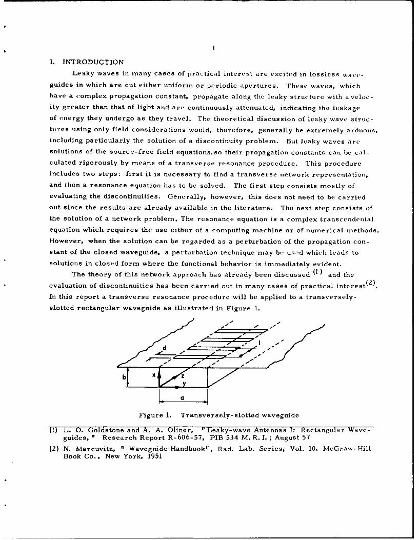
In this report a transverse resonance procedure will be applied to a transversely-
slotted rectangular waveguide as illustrated in Figure 1.
a
Figure 1. Transversely- slotted waveguide
(1) L. 0. Goldstone and A. A. Oliner, " Leaky-wave Antennas I: Rectangular Wave-guides, " Research Report R-606-57, PIB 534 M. R.I.; August 57
(2) N. Marcuvitz, " Waveguide Handbook", Rad. Lab. Series, Vol. 10, McGraw-HillBook Co., New York, 1951
The structure consists of an array of closely-spaced transverse slots which extendcompletely across the broad face of a rectangular waveguide. The waveguide isassumed to be infinite, and its slotted face is inserted in an infinite conducting p1.-ne.
(3)This struc';ure is well 1.-iown and has already been studied by R. F. HynemanHowever, it will be discussed here from a completely different point of view. Where-as Hyneman started from the general field equations and used iterative techniqueswith computing machines to get numerical results, in the following analysis a simple
perturbation technique will be used to obtain simple closed form expressions for theguide wavelength and attenuation constant.
Experimental measurements have also been made of the attenuation constant andguide wavelength, and these measured results are compared with the theoretical ex-pressions. It is found that very good agreement is obtained with the presently-derivedtheory, but that the calculations of Hyneman differ considerably from the measuredvalues. Furthermore, Hynernan indicates that a surface wave is prcsent on this struc-ture, but the present theory finds no evidence of the presence of such a wave. These
points are considered in detail below.
(3) R. F. Hyneman, " Closely-Spaced Transverse Slots in Rectangular Waveguide"IRE Transactions on Antennas and Propagation, Nb 4, pp. 335-342, October 1959.
3
I. ANALYSIS OF THE STRUCTURE
A few restrictions have to be made in order to simplify the analysis of the
problem. First, if the propagation constant of the leaky wave is to be regarded as a
perturbation on the closed waveguide propagation constants, the slots have to be small,
i. e., the ratio of length to width a/ d must be sufficiently great, the ratio of width to
free space wavelength d/k sufficiently small, and the spacing of the slots must be
large compared to their width. Under these conditions the only appreciable component
of the tangential electric field in the apertures is the z component and the characteris-
tics of the wave traveling on the structure are only slightly different from those of the
unperturbed case and are thus susceptible to analysis by perturbation methods.
Then, if this structure is to exhibit a leaky-wave behavior, the leakage of energy
has to be uniform. In other words, the structure has to be regarded as radiating
continuously and not as a discrete array of apertures. This will be the case if the
slots spacing is very small with respect to the free-space wavelength (I < Xi.
(a) Network Representation
A slotted guide where only one leaky wave propagates can, when viewed trans-
versely, be represented by a single length of transmission line short-circuited at one
end and terminated at the other end in an appropriate lumped network representing the
discontinuity.
It has already been mentioned that the only appreciable component of the tangen-
tial electric field is the z component, so that the mode propagating in the slotted
waveguide can be regarded as a perturbation on a TE mode propagating in the y
direction (H type mode (i) ); besides, "a" and "b" can be chosen such that only the
fundamental H type modes are never coupled on such structures 1), so that at the dis-
continuity the only modes which are excited are H-type modes of all orders, the low-
est one being the only one to propagate. Therefore, the waveguide viewed transversely
can be represented by a single piece of transmission line of length b, short circuited
at one end and terminated in the appropriate lumped network which will be determined
later. In fact, this single transmission line picture is valid only if b is large enough
so that none of the decaying modes can reach the back wall and be reflected with an
appreciable amplitude.
E = E 0 sin ( Ya exp (-jkzz) (1.1)
The z dependence is the usual exp (-jkzz) dependence and the y dependence is
assumed to be very similar to sin gy/a, the y dependence in the closed waveguide.

4
Ez between the slots, at x= b is equal to zero. Due to the periodicity of this
structure an expansion of Ez in a Fourier series can be carried out which yields the
following expression
+W0
E= Y a sin 1-a exp -jkz7 exp -j (pnf z/ ) (1.1z L n a Zn-- -so
If K is the transverse wave number, corresponding to each n there will be a Kn
such as
K k 2 g/a)2 - (kz + "-( )2 (1.3)n - (na -( 2ij
where kis replaced by k + 2nri , according to Eq. (1.2). Dut k does not differwhr z is repace by kz --
very much from k zO for which2
k2 - i_ + e , (1.4)a? z 0
and I is much smaller than X, k = 2m/X is much smaller than :r /I ). Therefore,
except for n 0, which corresponds to the lowest leaky mode, Kn is approximately
equivalent to -j(2,T n/1) and the corresponding modes decay rapidly away from the
plane x = b. Even for n= I this will be true since I and b are of the same order
at x = -b and the fields are too highly attenuated to be appreciably reflected, thus
justifying the single transmission line picture. The preceding discussion shows that
the electromagnetic energy is partly stored in the neighborhood of the discontinuities,
which corresponds to the decaying modes, and partly radiated away.
In the lumped network the radiated energy is represented by a conductance G
and the stored energy by a suspectance jB as illustrated in Fig. 2.
Fig. 2: Transverse equivalent network.

1. Determination of G
The conductance G could be found by computing the power radiated far from the
antenna. But the lowest H-type mode (n 0 in (1.3) ), being the only one which is
propagating, is the only mode which contributes to the power radiated in the far zone.
Therefore, in the determination of G we can disregard all the space harmonics, and,
in so far as G is concerned, the tangential electric field in the aperture can be taken
as
Ez = 0 sinLaY exp -jk z (1. )
Z a
Fig. 3: Parallel plate waveguideradiating into half-space
This corresponds to the situation represented in Fig. 3: G is the admittance equi-
valent to a parallel plate waveguide radiating into half space with the electric field
parallel to the guide walls. The conductance G is given by (4)
G P 0.8' - (1.6)
where Y0 is the characteristic admittance of the parallel plate waveguide and the
K the transverse wavenumber given by
-22 (1.7)
(1.6) can be rewritten
G G 2
- 1.6 where Go= 0. p85 _-57 (1.8)K
and G does not depend on K.
(4) N. Marcuvitz, ' Waveguide Handbook", Rad. Lab. Series, Vol. 10, McGraw-HillBook Co., New York, 1951, p. 191 Eq. 2b.
6
2. Determination of B
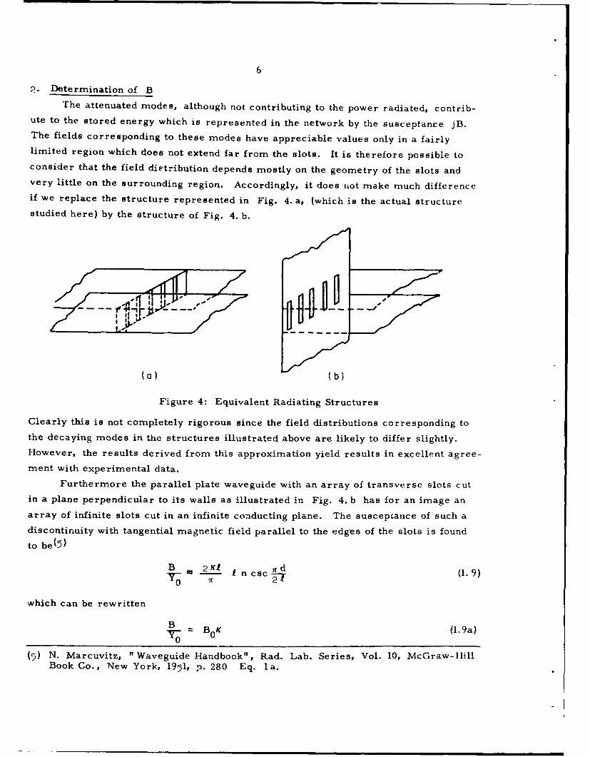
The attenuated modes, although not contributing to the power radiated, contrib-ute to the stored energy which is represented in the network by the susceptance jB.The fields corresponding to these modes have appreciable values only in a fairlylimited region which does not extend far from the slots. It is therefore possible toconsider that the field distribution depends mostly on the geometry of the slots andvery little on the surrounding region. Accordingly, it does not make much differenceif we replace the structure represented in Fig. 4. a, (which is the actual structurestudied here) by the structure of Fig. 4. b.
(a)b)
Figure 4: Equivalent Radiating Structures
Clearly this is not completely rigorous since the field distributions corresponding tothe decaying modes in the structures illustrated above are likely to differ slightly.However, the results derived from this approximation yield results in excellent agree-
ment with experimental data.Furthermore the parallel plate waveguide with an array of transverse slots cut
in a plane perpendicular to its walls as illustrated in Fig. 4. b has for an image anarray of infinite slots cut in an infinite conducting plane. The suscepcance of such adiscontinuity with tangential magnetic field parallel to the edges of the slots is found
to be(5)
"B 2M1 I n cac ,-d (1.9)
0
which can be rewritten
B = BOK (l.9a)0
(5) N. Marcuvitz, "Waveguide Handbook", Rad. Lab. Series, Vol. 10, McGraw-HillBook Co., New York, 1951, p. 280 Eq. la.

7
where Bo - __ .n csc (r d/2t), (which does not depend on K).
(b) Transverse resonance
The second part in this problem is to determine K from the network representa-tiorn by meanp of a resonance procedure. The resonance equation can be written :n the
following manner
Y(K) = Y(K) + Y(K)= 0 (2.10)where Y (K) is (see Fig. 2) the admittance of the short-circuited piece of transmissionline i. e. -j Y0 cot K b and Y(K) the net admittance of the lumped network represen-ting the discontinuities i. e. G + jB. Therefore (2.10) becomes
-j Y0 cot Kb + jB + G =0 (2.11)
or
GO-j cot K b + jB 0 K + IF = 0 (2.12)
thus,Go
cot Kb= B 0K -j K (2.13)
and dividing both sides by Kb, we see that
cot Kb B0 G0 (2.14)K B = T- K2-b
Let xb = u, Eq. 2.14 becomes
cot ub B0 G0 b (215)U -Ju
This resonance equation should identical to the equation obtained by Hyneman(b) inwhich he started from %.he field equations. But whereas the left-hand sides are iden-tical, the right-hand side is here in a simple compact form as opposed to Hyneman'swhich uses a product of complicated series and integrals. However, once theseintegrals and series are evaluated the results should be the same, since in the Wave-guide Handbook the discontinuities were evaluated from the field equations. One ofthe principal advantages of the approach used here is that it does not carry out these
complicated computations and uses results already available.
(6) See Ref. no. (3) Eq. 14 p. 337.
8
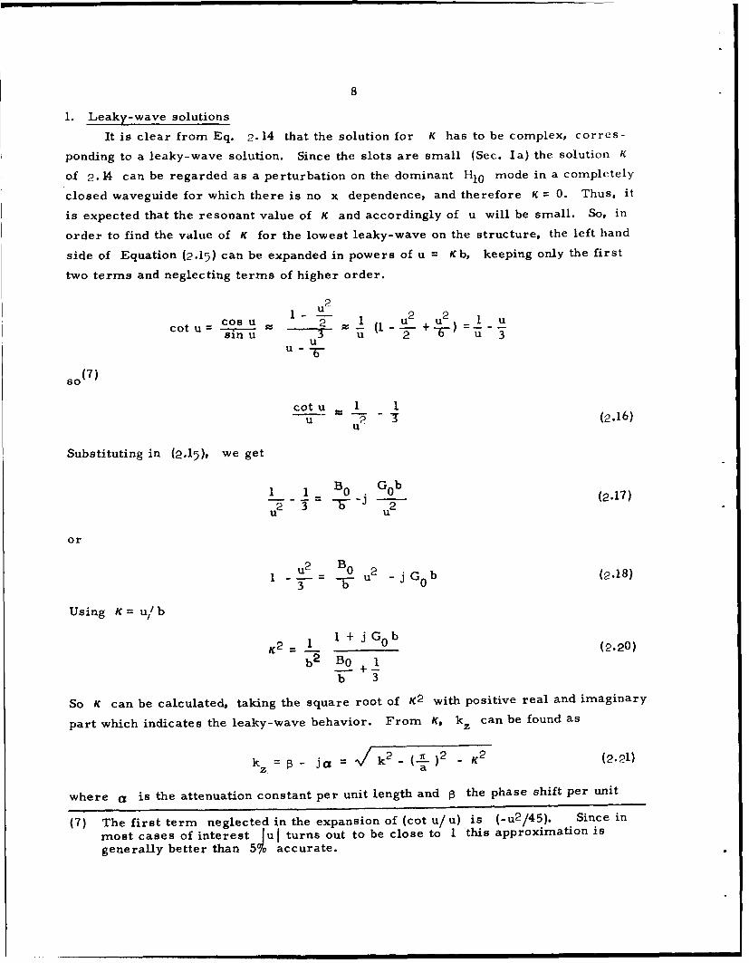
1. Leaky-wave solutions
It is clear from Eq. 2.14 that the solution for K has to be complex, corres-
ponding to a leaky-wave solution. Since the slots are small (Sec. Ia) the solution K
of 2.14 can be regarded as a perturbation on the dominant H10 mode in a completely
closed waveguide for which there is no x dependence, and therefore K = 0. Thus, it
is expected that the resonant value of K and accordingly of u will be small. So, in
order to find the value of K for the lowest leaky-wave on the structure, the left hand
side of Equation (2.15) can be expanded in powers of u = Kb, keeping only the first
two terms and neglecting terms of higher order.
1 u2 1I u2 u2 1 ucoo u 2 u u I -+ )cot U = I%----u = +
uU-
so (7)
cotu 1 1(u 2 (.6u
Substituting in (2.15), we get
1 1 B 0 G 0 bu2 - -u- 2 -j
or
u2 -=B0 u2 -j G0 b (2.18)3 b
Using K= u/b
2 1 +j G 0 b (2.20)b2 B 0 +
b 3
So K can be calculated, taking the square root of K2 with positive real and imaginary
part which indicates the leaky-wave behavior. From K, kz can be found as
kz = j - = k 2 - ('l)2 - K 2 (2.21)
z a
where a is the attenuation constant per unit length and 1 the phase shift per unit
(7) The first term neglected in the expansion of (cot u/u) is (-u 2 /45). Since in
most cases of interest Jul turns out to be close to 1 this approximation is
generally better than 5% accurate.
nmmummmm m||~ m m II II l INIw
9
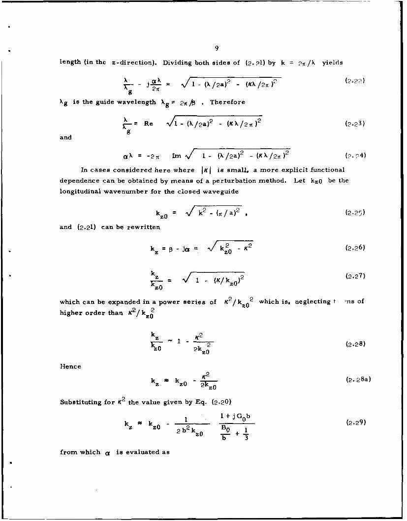
length (in thc z-direction). Dividing both sides of (2. 21) by k = 2A / yields
X a - /2a - (KX/2t (2.??)
g
Xg is the guide wavelength Xg = 2 . Therefore
K- Re - ( (2.23)
gand
ak = -24 )m 1- (k/2a)2 1 (K/2 )2 (4)
In cases considered here where IKI is small, a more explicit functional
dependence can be obtained by means of a perturbation method. Let kzO be the
longitudinal wavenumber for the closed waveguide
kz0 k 2 -(t/a) 2 , (2-25)
and (2.21) can be rewritten
k =t-jCz= k 2 _ K2 (2.26)z zO
kz - k i 2 (2.27)zO
(K/kz0)2
which can be expanded in a power series of K2 /kz 02 which is, neglecting t -ns of
higher order than / k 2
kz ,Z K2 2 (2.28)
2kz
Hence
- K2 (2.28a)kz kz0 V
Substituting for K2 the value given by Eq. (2.20)
k 1 1+ jGb (2.29)z zo 2 b2k BBO +(S b 3
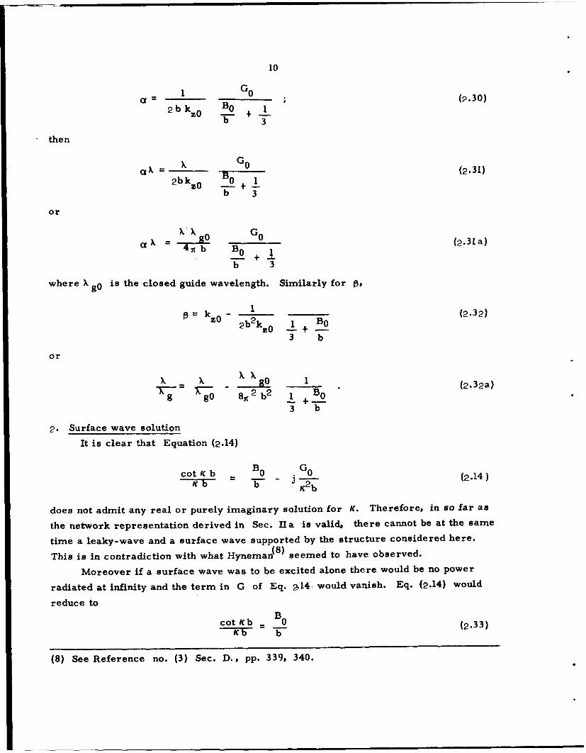
from which a is evaluated as
10
a= 0___ (2.30)
bkzo Bo +b 3
then
-X- B 0- (2.31)2bkz0 0 1
b 3
or
X= 0 B 0 (2.31 a)0_ +!B
b 3
where X go is the closed guide wavelength. Similarly for Ps
k ~ B (2.32)kz0 2b 2 k3 0 1 BO
3 b
or
XXX X .. go 1 (2.32a)
2 Bog gO 8, 2 b2 1 + 0
3 b
2. Surface wave solution
It is clear that Equation (2.14)
cot K b B 0 0 (214colb - (2.14)
K2b
does not admit any real or purely imaginary solution for K. Therefore, in so far as
the network representation derived in Sec. Hia is valid, there cannot be at the same
time a leaky-wave and a surface wave supported by the structure considered here.(8)
This is in contradiction with what Hyneman seemed to have observed.
Moreover if a surface wave was to be excited alone there would be no power
radiated at infinity and the term in G of Eq. a14 would vanish. Eq. (2.14) would
reduce to
cot Kb B0 (2.33)
(8) See Reference no. (3) Sec. D., pp. 339, 340.

11
0.40 -.70 -
0.30
0.20 PARAMETER
0.08
0.06
0.04
0.02
""--0.95
0.01 NETWORK PROCEDURE - - -
0.445 *"So 12 -7-r
0033
HYNEMAN
b = 0.466
d = 0.033
0.1 0.2 0.3 0.4
Fig.5. THEORETICAL ATTENUATION vs.SLOT SPACING IN WAVELENGTHS M.R.1.- 19103

12
2/
ANTENNA PARAMETERSa 0.9"*"", -_ b -0.4" 11o..-- 1 I.0.30 ~
0.8 d 0.032" -
(nepers) /
-THEORETICAL RESULTSX EXPERIMENTAL RESULTS
-- HYNEMAN'S RESULTS
0.7 0.8 0.9
2a
Fig.6. ATTENUATION vs. WAVELENGTH
1.0
-- THEORETICALERETCL
0xEXPERIMENTAL
0.6---------------
OA
ANTENNA PARAMETERS __
a = 0.9"10.2- b =0.4' _ _
L = 0.3"i
0.01 ,d = 0.032"0.40.60 .0.6 0.7S 0.8
2a
Fig.7. vs. WAVELENGTHg
M.R.I.-19104
13
II. RESULTS
a. Theoretical Results
Froni the expression (2.24) the normalized attenuation constant a/k = 0•k/Pt
was computed. The results are plotted on Fig. 5 for several values of a /X, ver-
sus the spacing of the slots 1/X. On the same figure are compared the results
obtained by Hyneman for a waveguide only slightly different: the obviously disagree.
On Fig. 6 the plots of attenuation constants Ca versus X/2a are found first
as computed from Eq. (2.24) and then from the perturbational expression as in (2. 31)
(2.31). The discrepancy between these two curves, though increasing with the wave-
length, is always relatively small. In fact, whereas neglecting u2 /45 in the
expansion of cot u/u is an excellent approximation since lul is found to be close
to 1, it is not such a good approximation to neglect terms of the order K4 (8k 0 ) in
the expansion of kz in (2.27) because for b= 0.4", IKI = Iul/b is equivalent to
IKd Z 2.5.In any case, the perturbation expression is a far better approximation than
Hyneman' s results( 8 ) which are plotted on the same figure and show clearly the
functional dependence of the leaky-wave characteristics.
Finally on Figure 7 X/(Xg) versus X/2a is plotted as given by Eq. (2.23).
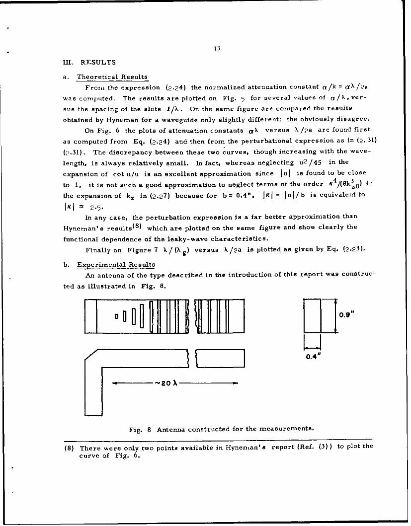
b. Experimental Results
An antenna of the type described in the introduction of this report was construc-
ted as illustrated in Fig. 8.
0.4"
S~~~20 -
Fig. 8 Antenna constructed for the measurements.
(8) There were only two points available in Hynenian' s report (Ref. (3)) to plot the
curve of Fig. 6.

14
In order to avoid reflections at the open end of the guide, the length of the
antenna was taken to be around 20 wavelengths so that no wave reach the end with
an appreciable amplitude. In addition, it was found necessary to increase progres-
sively the length of the slots, because if they all extended completely across the broad
face, the discontinuity in the neighborhood of the first ones could be important enough
to excite a strong space-wave which would almost conceal completely the leaky wave.
The waveguide was inserted in a large aluminum ground plane 8' X 8' and
radiated into a microwave darkroom approximately 10' X 10' X 10' the walls of
which were covered with an absorbing material. The probe consists of a length of
flexible miniature coaxial cable which is supported by a polyfoam structure and is
covered by absorbing material to minimize as much as possible the distortion of the
field. The probe carriage is motor driven and its travel is controlled by limit swit-
ches and a reversing switch.
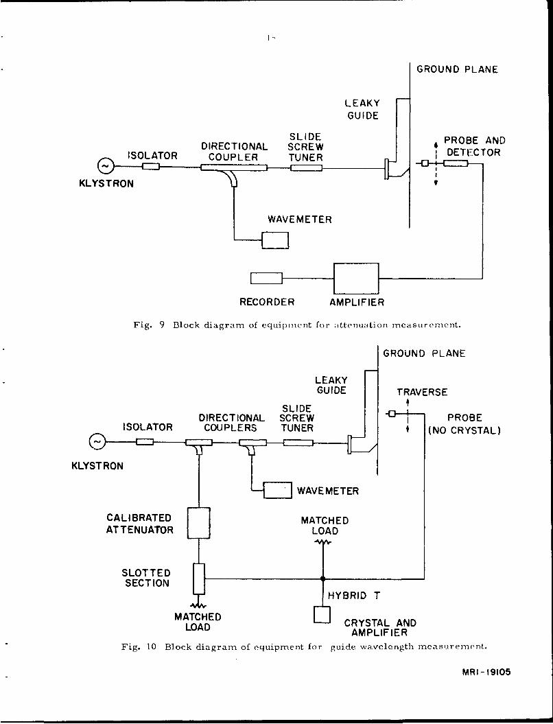
I. Attenuation measurements.
The probe is oriented perpendicularly to the slotted face of the antenna. The
signal available from the probe is fed to a recorder through a DC amplifier (Fig. 9).
As the probe travels along the antenna at a uniform speed, the recorder plots the
amplitude distribution of the leaky wave. These data are plotted on semi-log graph
paper, the slope of the straight line which best fits a particular set of data is used to
compute the attenuation constant. The results so obtained are shown on Fig. 6.
2. Phase measurements.
The phase measurements are taken with the configuration slightly modified. A
null method is used to compare the phases of the aperture field and of a reference
signal. The magnitude and phase of this reference are adjusted by means of a cali-
brated attenuator and a slotted section. Comparison of the phases is accomplished by
a hybrid tee junction. A block diagram of the set up used here is shown in Fig. 10.
The experimental values of the guide wavelength are plotted on Fig. 7.
GROUND PLANE
LEAKYGUIDE
SLIDEPRBAN
DIRECTIONAL SCREW PROBE ANDISOLATOR COUPLER TUNER iDETECTOR
KLYSTRON 'J'ý r
WAVEMETER
RECORDER AMPLIFIER
Fig. 9 Block diagram of equipment for attenuation measurement.
GROUND PLANE
LEAKYGUIDE TRAVERSE
SLIDE
DIRECTIONAL SCREW IPROBEISOLATOR COUPLERS TUNER | (NO CRYSTAL)
KLYSTRON
WAVE METER
CALIBRATED MATCHEDAT TENUATOR LOAD
SLOTTEDSECTION
HYBRID T
MATCHED CRYSTAL ANDLOAD AMPLIFIER
Fig. 10 Block diagram of equipment for guide wavelength measurement.
MRI- 19105
16
IV. CONCLUSIONS
The experimental results obtained for the attenuation constant and the guide
wavelength agree very satisfactorily with the theoretical values (see Fig. 6 and 7).
This fact shows that those approximations which were made in Section ia were
perfectly justified.
The validity of the network representation used here seems therefore to be fully
guaranteed, and the results derived therefrom are in far better agreement with
measured values than any results previously derived by other methods.
Furthermore, it becomes very doubtful that this structure could excite a surface
wave together with a leaky wave, as indicated by Hyneman.

Distribution List
Organization No. of Copies Organization No. of Copies
AFGC (PGAPI) ASD (ASRNRE-3)Eglin, AFB, Fla. 1 Attn: Mr. P. Springer
Wright-Patterson AFB, Ohio
RADC (RAALD) Attn:Docurnents LibraryGriffiss AFB, N.Y. 1 Foreign Technology Division (TDEE)
Wright-Patterson AFB, OhioRADC (RCE)Attn: Dr. John S. Burgess WADD (SWDRTR, Mr. A.D. Clark)Griffiss AFB, N.Y. Directorate of System Engineering
Dyna Soar Engineering OfficeAF Missile Dev. Cent. (MDGRT) Wright-Patterson AFB, OhioHolloman AFB, New Mexico
Lt. Col. Jensen (SSTRE)Director of Resident Training Space Systems Division3380th Technical Training Group Air Force Unit Post OfficeKeesler AFB, Mississippi Los Angeles 45, Calif.Attn:OA-3011 Course
DirectorSAC (Operations Analysis Office) Evans Signal LaboratoryOffutt AFB, Nebraska 1 Belmar, New Jersey
Attn: Mr. O.C. WoodyardAULMaxwell AFB, Alabama Commanding General
USASRDLAF Missile Test Center Ft. Monmouth, N. J.Partick AFB, Fla. Attn: Tech. Doc. Ctr.Attn: AFMTC, Tech Library SIGRA/ SL-ADTMU- 135
Department of the ArmyUSAF Security Service (CLR) Office of the Chief Signal OfficerSan Antonio, Texas Washington 25, D.C.
Attn: ISGRD-4a- IOAR (RROS, Col. J. R. Fowler)Tempo D Massachusetts Institute of Technology4th and Independence Avenue Signal Corps Liaison OfficerWashington 25, D.C. Cambridge 39, Mass
Attn: A. D. BedrosianHq. USAF (AFOAC-S/ E) Rm. 26-131Communications-Electronics DirectorateWashington 25, D.C. 1 Commanding General
USAS RDLAFOSR, OAR (SRYP) Ft. Monmouth, N.J.Tempo D Attn: Mr. F.J. Triola4th and Independence AvenueWashington 25, D.C. Commanding General
USAMCHq. OAR (RROSP, Maj. R.W. Nelson) Attn: AMCRD-RS-PE-ETempo D Washington 25, D.C.4th and IndependenceWashington Z5, D.C. 1 Director
U.S. Army OrdnanceASD (ASNXRR) Ballistic Research LaboratoriesWright-Patterson AFB, Ohio 1 Aberdeen Proving Ground, Md.
Attn: Ballistic MeasurementsASD (ASRNC, Mr. W. J. Portune) Laboratory
Wright-Patterson AFB, Ohio 1
Distribution List (continued)
Organization No. of Copies Organization No. of Copies
Ballistic Research Laboratories DirectorAberdeen Proving Ground, Md. National Security AgencyAttn: Tech. Info. Branch I Ft. G.G. Meade, Maryland
Attn: C3/ CDLGuided Missile Fuze LibraryDiamond Ordnance Fuze Labs. National Aeronautical Space AgencyWashington 25, D.C. Langley Aeronautical Research Lbs.Attn: R.D. Hatcher, Chief Langley, Va.Microwave Dev. Section 1 Attn: Mr. Cliff Nelson
Commanding General OFCRL, OAR (CRXRA-Stop 39)USASRDL L.G. Hanscom Field, Bedford, MassFort Monmouth, N. J. (to be shipped under separate coverAttn: SIGFM/ EL-AT 1 as reports go to our documents
section) 10Redstone Scientific Info. CenterU.S. Army Missile Command AFCRL, Office of AerospaceRedstone Arsenal, Ala. 5 Research (CRD)
Attn: Contract FilesCommanding General, SIGFM/EL-PC L.G. Hanscom Feld,USASRDL Bedford, Mass. 2Ft. Monmouth, N.J.Attn: Dr. H.H. Kedesdy AFCRL, Office of AerospaceDeputy Chief, Chem-Physics Research (CRD)Branch 1 Attn: Crylyle J. Sletten
L.G. Hanscom FieldDefense Documentation Center (DDC) Bedford, Mass. 3Cameron StationAlexandria, Va. 10 Hq. ESD (ESRDW,
Maj. J.J. HobsonLibrary L.G. Hanscom Field,National Bureau of Standards Bedford, Mass.Boulder LaboratoriesBoulder, Colorado 2 Electronic Systems Division
(AFSC)Defense Research Member Technical Info. ServicesCanadian Joint Staff Division (ESAT)2450 Massachv;setts Ave., N.W. L.G. Hanscom FieldWashington 8, D.C. 1 Bedford, Mass.
Scientific and Technical Info. Facility Hq. AFCRL, OARAttn: NASA Representative (S-AK/ DL) (CRXR, J. R. Marple)Post Office Box 4700 L.G. Hanscom Field,Bethseda, Md. 1 Bedford, Mass.
National Bureau of Standards Chief,U.S. Department of Commerce Bureau of ShipsWashington 25, D.C. Department of the NavyAttn: G. Shapiro (Chief, Eng. Elec. Washington 25, D.C.Sec. Electricity and Electronics Attn: Code 690Division) 1
Chief, Bureau of Naval WeaponsOffice of Scientific Intelligence Department of the NavyCentral Intelligence Agency Washington 25, D.C.2430 E. Street, N.W. Attn: DLI-31 2Washington 25, D.C. 1
2

Distribution List (continued)
Organization No. of Copies Organization No. of Copies
Commander Commanding Officer and DirectorU.S. Naval Air Missile Test Center U.S. Navy Electronics LaboratoryPoint Mugu, Calif. (Library)Attn: Code 366 1 San Diego 52, Calif.
U.S. Naval Ordnance Labs. CommanderWhite Oak U.S. Naval Air Test CenterSilver Spring 19, Md. Patuxent River, Md.Attn: The Library 1 Attn: ET-315, Antenna Branch
Commander Material Laboratory, Code 932U.S. Naval Ordnance Test Station New York Naval ShipyardChina Lake, Calif. Brooklyn 1, New YorkAttn: Code 753 1 Attn: Mr. D. First
Librarian Chief, Bureau of ShipsU.S. Naval Postgraduate School Department of the NavyMonterey, Calif. 1 Washington 25, D.C.
Attn: Code 817BNational Aeronautics andSpace Administration AFSC STLO (RTSNW)Attn: Antenna Systems Branch c/ o Dept of the NavyGoddard Space Flight Center Room 3710 Main Navy Bldg.Greenbelt, Md. 1 Washington 25, D.C.
Director Aero Geo Astro Corp.U.S. Naval Research Labs. 1200 Duke StreetWashington 25, D.C. Alexandria, Va.Attn: Code 2027 2 Attn: Library
Dr. J.I. Bohnert Aerospace Corp.Code 5210 Box 95085U.S. Naval Research Laboratory Los Angeles 45, Calif.Washington 25, D.C. 1 Attn: Library
Commanding Officer and Director Airborne Instruments Laboratory, Inc.U.S. Navy Underwater Division of Cutler HammerSound Laboratory Walt Whitman RoadFort Trumbull, New London Melville, New YorkConnecticut 1 Attn: Library
Chief of Naval Research Aircom, Inc.Department of the Navy 48 Cummington StreetWashington 25, D.C. Boston, Mass.Attn: Code 427 1
Andrew AlfordCommanding Officer Consulting EngineersU.S. Naval Air Development Center 299 Atlantic AvenueJohnsville, Penn. Boston 10, MassAttn: NADC Library 1
Aerospace Corp.
Office of Naval Research Satellite ControlBranch Office, London Attn: Mr. R.C. HansenNavy 100, Box 39 P.O. Box 95085F. P.O. N.Y., N.Y. 10 Los Angeles 45, Calif.
3

Distribution List (continued)
Organization No. of Copies Organization No. of Copies
ACF Electronics Div. Brush Beryllium CompanyElectro-Physics Labs. 17876 St. Clair StreetAttn: Library Cleveland 10, Ohio3355 52nd Avenue Attn: N.W. BassHyattsville, Md. I
Chance Vought Corp.Battelle Memorial Institute 9314 W. Jefferson Blvd.505 King Avenue Dallas, TexasColumbus 1, Ohio Attn: A.D. Pattullo,Attn: Wayne E. Rife, Project Leader LibrarianElectrical Engr. Division 1
Chance Vought Corp.Bell Aircraft Corp. Vought Electronics DivisionP.O. Box 1 P.O. Box 5907Buffalo 5, N.Y. Dallas 22, TexasAttn: E.P. Hazelton, Librarian 1
Chu AssociatesBell Telephone Labs. P.O. Box 387Murray Hill, N.J. Whitcomb Avenue
Littleton, Mass.Bell Telephone Labs, Inc.Technical Information Library Collins Radio Co.Whippany Laboratory 1 855 35th Street, N. W.Whippany, N.J. Cedar Rapids, IowaAttn: Technical Reports Librarian Attn: Dr. R. L. McCraery
Bendix Pacific Division Cornell Aeronautical Laboratory Inc.11600 Sherman Way 4455 Genesee StreetNorth Hollywood, Calif. Buffalo 21, New YorkAttn: Engr. Library I Attn: Librarian
Bendix Radio Division Dalmo Victor CompanyBendix Aviation Corp. A Division of Textron, Inc.E. Joppa Road 1515 Industrial WayTowson 4, Md. Belmont, Calif.Attn: Dr. D.M. Allison, Jr. Attn: M.E. Addams,Director, Engr. and Research I Technical Librarian
Bjorksten Research Labs, Inc. Dorne and Margolin, Inc.P.O. Box 265 29 New York AvenueMadison, Wis. Westbury, L.I., N.Y.Attn: Librarian 1
Aircraft DivisionBoeing Airplane Co. Douglas Aircraft Co,, Inc.Pilotless Aircraft Division 3855 Lakewood Blvd.P.O. Box 3707 Long Beach, Dalif.Seattle 24, Washington Attn: Technical LibraryAttn: R.R. BarberLibrary Supervisor 2 Douglas Aircraft Co., Inc.
3000 Ocean Park Blvd.Boeing Company 3801 Santa Monica, Calif.3801 S. Oliver Street Attn: P. Duyan, Jr.Wichita 1, Kansas Chief, Electrical/ ElectronicsAttn: K.C. Knight, SectionLibrary Supervisor 1
4

Distribution List (continued)
Organization No. of Copies Organization No. of Copies
Douglas Aircraft Co., Inc. ITT Federal Laboratories2000 North Mem3rial Drive Technical LibraryTulsa, Oklahoma 500 Washington AvenueAttn: Engr. Librarian, D-250 I Nutley 10, N.J.
Electromagnetic Research Corp. Gabriel Electronics Division5001 College Avenue Main and Pleasant StreetsCollege Park, Md. Millis, Mass.Attn: Mr. M. Katzin Attn: Dr. Edward Altshuler
Electronics Communication General Electric Company1830 York Road Building 3 - Rm 143-1Timonium, Md. I Electronics Park
Syracuse, N.Y.Convair, A Division of General Attn: Y. BurkeDynamics Corp. Documents LibraryFort Worth, TexasAttn: K.G. Brown General Electric Co.Division Research Librarian I Missile and Space Vehicle Dept.
3198 Chestnut StreetConvair, A Division of General Philadelphia, Pa.Dynamics Corp. Attn: Documents Library3165 Pacific HighwaySan Diego 12, Calif. General Electric CompanyAttn: Mrs. Dora Burke 3750 D StreetEngr. Librarian 1 Philadelphia 24, Pa.
Attn: Mr. H.G. LewElectronic Speciality Co., Missile Pnd Space Vehicle Dept.5121 San Fernando RoadLos Angeles 39, Calif. General Precision Laboratory, Inc.Attn: D.L. Margerum 63 Bedford RoadChief Engineer, Pleasantville, N. YRadiating Sys tems Division 1 Attn: Librarian
Emerson ann Curning, Inc. Goodyear Aircraft Corp.59 Walpole Street 1210 Massillon RoadCanton, Mass. Akron 15, OhioAttn: Mr. W. Cuming 1 AttnL Library, Plant G
Emerbon Electric Mfg. Co. Granger Associates8100 W. Florissant Avenue Electronic SystemsSt. Louis 21, Miss. 974 Commerical StreetAttn: Mr. E.R. Breslin, Palo Al t o, Calif.Librarian 1 Attn: J.V.N. Granger,
PresidentEmerson Radio-Phonograph Corp.Emerson Research Laboratories Grm-nman Aircraft Engr. Corp*1140 Eastwest Highway Bethpage, L.I., N.Y.Silver Spring, Maryland Attn: Engr. LibrarianAttn: Mrs. R. Corbin, Librarian I Plant No. 5
Fairchild Stratos Corp. Hallicrafters Co.Hagerstown, Md. 4401 W. 5th AvenueAircraft Missiles Division Chicago 24, Ill.Attn: Library 1 Attn: L. LaGioia, Librarian
• 5

Distribution List (continued)
Organization No. of Copies Organization No. of Copies
The Hallicrafters Co. Dr. Henry Jasik, Consulting Engineer5th and Kostner Avenues 298 Shames DriveChicago 24, Ill. Brush Hollow Industrial ParkAttn: H. Hodara Westbury, N.Y.Head of Space Communication 1
Lockheed Aircraft Corp.Hoffman Electronics Corp. 2555 N. Hollywood Way3761 South Hill Street California Division Engineering Labs.Los Angeles 7, Calif. Department 72-25 Plant A-i, Bldg. 62-1Attn: Engineering Library Burban Calif.
Attn: N.C. Harnois IHughes Aircraft Co.Antenna Department Lockheed Aircraft Corp.Building 12, Mail Station 2714 Missiles and Space DivisionCulver City, Calif. Technical Information CenterAttn: Dr. W.H. Kummer 1 2351 Hanover Street
Palo Alto, Calif. 2Sperry-Rand Research CenterRoute 117 (North Road) Martin-Marietta Corp.Sudbury, Mass 12250 S. State Highway 65Attn: Mr. G. Meltz 1 Jefferson County, Colo.
Attn: Mr. J. McCormickHughes Aircraft CompanyFlorence Avenue and Teale Streets The Martin Co.Culver City, Calif. Baltimore 3, Md.Attn: L.L. Balin Attn: Engr. LibraryManager, Antenna Dept. 1 Antenna Design Group
Hughes Aircraft Co. Mathematical ReviewsAttn: Mr. L. Stark, Microwave Dept. 190 Hope StreetRadar Laboratory, P.O. Box 2097 Providence 8, R.I.Building 600, Mail Station C-15ZFullerton, Calif. 1 The W. L. Maxson Corp.
475 10th AvenueInternational Business Machines Corp. New York, N.Y.Space Guidance Center Attn: Miss D. ClarkFederal Systems DivisionOwego, Tioga County, N.Y. Mc Donnell Aircraft Corp.Attn: Technical Reports Center 1 Dept. 644
Bos 615 St. Louis 66, Mo.International Resistance Co. Attn: C.E. Zollar401 N. Broad Street Engineering LibraryPhiladelphia 8, Pa.Attn: Research Library Mc Millan Laboratory Inc.
Brownville AvenueITT Federal Laboratories Ipswich, Mass.3700 E. Pontiac Street Attn: Security OfficerFort Wayne 1, Indiana Document RoomAttn: Technical Library
Melpar, Inc.Atlantic Research Corp. 3000 Arlington Blvd.Shirley Highway at Edsall Rd. Falls Church, Va.Alexandria, Va. Attn: Engr. Technical LibraryAttn: D.C. Ports
Microwave Associates, Inc.South AvenueBrulington, Mass.
6

Distribution List (continued)
Organization No. of Copies Organization No. Copies
Microwave Development Labs. Inc. Philco Corp.92 Broad Street Research DivisionWellesley 67, Mass. Union Meeting PondAttn: N. Tucker, Blue Bell, Pa.General Manager l Attn: Research Librarian
The Mitre Corp. Pickard and Burns, Inc.244 Wood Street 103 Fourth AvenueLexington 73, Mass. Waltham 54, Mass.Attn: Mrs. Jean E. Claflin Attn: Dr. R.H. WoodwardLibrarian
Polytechnic Research andMotorola, Inc. Development Co., Inc.8201 E. McDowell Rd. 202 Tillary StreetPhoenix Arizona Brooklyn 1, New YorkAttn: Dr. T.E. Tice I Attn: Technical Library
Motorola, Inc. Radiation, Inc.Phoenix Research Laboratory Melbourne, Florida2102 N. 56 Street Attn: R. F. Systems DivisionPhoenix, Arizona Technical Info. CenterAttn: Dr. A.L. Aden
Radiation Systems, Inc.National Research Cohincil 440 Swann AvenueRadio and Electrical Engineering Alexandria, Va.Division Attn: LibraryOttawa, Ontario, CanadaAttn: Dr. G.A. Miller, Head RCA LaboratoriesMicrowave Section 1 David Sarnoff Research Center
201 Washington RoadNorth American Aviation, Inc. Princeton, N. J.12214 Lakewood Blvd. Attn: Miss F. Cloak, LibrarianDowney, Calif.Attn: Technical Info. Center RCA(495-12) Space and Info. Systems Defense Electronic ProductsDivision Building 10, Floor 7
Camden 2, N.J.North American Aviation, Inc Attn: Mr. Harold J. SchraderLos. Angeles International Airport Staff EngineerLos Angeles 45, Calif. Organization of Chief TechnicalAttn: Engr. Tech. File 1 Administrator
Page Communications Engrs. Inc. RCA2001 Wisconsin Avenue, N.W. Missile Control and Electronics DivisionWashington 7, D.C. Bedford StreetAttn: R. Temple, Librarian I Burlington, Mass.
Attn: LibrarianNorthrop CorporationNorair Division RCA1001 E. Broadway Surface Communications Systems Lab.Hawthorne, Calif. 75 Varick StreetAttn: Technical Info. 3924-31 1 New York 13, N.Y.
Attn: Mr. S. Krevsky
7

Distribution List (continued)
Organization No. of Copies Organization No.of Copies
RCA Ryan Aeronautical Co.West Coast Missile and Surface Radar Division 2701 Harbor DriveEngineering Library, Building 306/2 Lindbergh FieldAttn: L. R. IHund, Librarian San Diego 12, Calif.8500 Balboa Blvd. Attn: LibraryVan Nuys, Calif. I
Sage Laboratories, Inc.RCA 3 Huron DriveDefense Electronic Products Natick, Mass.Advanced Military SystemsPrinceton, N.J. Sanders Associates, Inc.Attn: Mr. David Shore 1 95 Canal Street
Nashua, New HampshireDirector, USAF Project RAND Attn: Mr. N. R. WildVia: AF Liaison OfficeThe Rand Corporation Sandia Corporation1700 Main Street P.O. Box 5800Santa Monica, Calif. 1 Albuquerque, New Mexico
Attn: Records Management andThe Rand Corporation Services Department1700 Main StreetSanta Monica, Calif. Scanwell Laboratories, Inc.Attn: Tech. Library 1 6601 Scanwell Lane
Springfield, Va.Rantec Corp.23999 Ventura Blvd. STL Technical LibraryCalabasas, Calif. Document AcquisitionsAttn: Grace Keener, Space Technology Laboratories, Inc.Office Manager I P.O. Box 95001
Los Angeles 45, Calif.Raytheon CompanyBoston Post Road Sperry Gyroscope Co.Wayland, Mass. Great Neck, L.I., N.Y.Attn: Mr. Robert Borts 1 Attn: F.W. Turnbull
Engineering LibrarianRaytheon CompanyWayland Laboratory Stanford Research InstituteWayland, Mass. Documents CenterAttn: Miss A.G. Anderson Menlo Park, Calif.Librarian 1 Attn: Acquisitions
Raytheon Company Sylvania Electric Products, Inc.Missile Systems Division 100 First AvenueHartwell Road Waltham 54, Mass.Bedford, Mass Attn: Charles A. Thornhill,Attn: D.H. Archer 1 Report Librarian
Waltham Laboratories LibraryRemington Rand UNIVACDivision of Sperry Rand Corp. Sylvania Elec. Prod. Inc.P.O. Box 500 Electronic Defense LaboratoryBlue Bell, Pa. P.O. Box 205Attn: Engineering Library 1 Mountain View, Calif.
Attn: LibraryRepublic Aviation CorporationFarmingdale, L. I., N. Y. Sylvania Reconnaissance Systems Lab.Attn: Engineering Library 1 Box 188, Mountain View, Calif.
Attn: Marvin D. Waldman I8

Distribation List (continued)
Organization No. of Copies Organization No. of Copies
TRG, Inc. University of Southern Calif.400 Border Street University ParkEast Boston, Mass Los Angeles, Calif.Attn: Dr. Alan F. Kay Attn: Dr. R. L. Chaan
AS Thomas, Inc Director, Engineering Center
355 Providence Highway Case Institute of TechnologyWestwood, Mass. Electrical Engineering DepartmentAttn: A.S. Thomas, President 1 10900 Euclid Avenue
Cleveland, OhioTexas Instruments, Inc. Attn: Professor R. Plonsey6000 Lemmon AvenueDallas 9, Texas Columbia UniversityAttn: J. B. Travis Department of Electrical EngineeringSystems Planning Branch I Morningside Heights, N.Y.
Attn: Dr. SchlesingerWestinghouse Electric Corp.
Electronics Division University of Southern CalifFriendship Int'l Airport Box 1987 Engineering CenterBaltimore 3, Md. University ParkAttn: Engineering Library 1 Los Angeles 7, Calif.
Attn: Z.A. KaprielianLibrary Geophysical Institute Associate Professor ofof the University of Alaska Electrical EngineeringCollege, Alaska
Cornell UniversityBrown University School of Electrical EngineeringDepartment of Electrical Engineering Ithaca, New YorkProvidence, R.I. Attn: Prof. G.C. DalmanAttn: Dr. C.M. Angulo I
University of FloridaCalifornia Institute of Technology Department of Electrical EngineeringJet Propulsion Laboratory Gainesville, Fla.4900 Oak Grove Drive Attn: Prof. M.H. Latour, LibraryPasadena, Calif.Attn: Mr. I.E. Newlan Library
Georgia Technology Research InstituteCalifornia Institute of Technology Engineering Experiment Station1201 E. California Drive 722 Cherry Street, N.W.Pasadena, Calif. Atlanta, GeorgiaAttn: Dr. C. Papas Attn: Mrs. J.H. Crosland, Librarian
Space Sciences Laboratory Harvard UniversityLeuschner Observatory Technical Reports CollectionUniversity of California Gordon McKay LibraryBerkeley 4, Calif. 303 Pierce HallAttn: Dr. S. Silver, Oxford StreetProfessor of Engineering Science Cambridge 38, Mass.and Director, Space Sciences Attn: LibrarianLaboratory
Harvard College ObservatoryUniversity of California 60 Garden StreetElectronics Research Lab. Cambridge 39, Mass.332 Cory Hall Attn: Dr. F. L. WhippleBerkeley 4, Calif.Attn: J. R. Whinnery 1
9

Distribution List (continued)
Organization No. of Copies Organization No. of Copies
University of Illinois McGill UniversityDocuments Division Library Department of Electrical EngineeringUrbana, Illinois 1 Montreal, Canada
Attn: Dr. T.PavlasekUniversity of IllinoisCollege of Engineering University of MichiganUrbana, Illinois 1 Electronic Defense GroupAttn: Dr. P.E. Mayes Institute of Science and TechnologyDepartment of Electrical Engineering Ann Arbor, Michigan
Attn: J.A. Boyd, SupervisorHarvard University
Gordon McKay Laboratory University of Michigan9 Oxford Street Office of Reseafch AdministrationC;,mbridge 38, Mass. Radiation LaboratoryAttn: R.W.P. King, 912 N. Main StreetProfessor of Applied Physics 1 Ann Arbor, Michigan
Attn: Mr. R.E. HiattHarvard UniversityGordon MdKay Laboratory University of Michigan9 Oxford Street Engineering Research InstituteCambridge 38, Mass. Willow Run LaboratoriesAttn: Prof. S.R. Seshadri 1 Willow Run Airport
Ypsilanti, MichiganThe Johns Hopkins University Attn: LibrarianHomewood CampusBaltimire 18, Md. University of MinnesotaAttn: Dr. D.E. Kerr, Minneapolis 14, MinnesotaDepartment of Physics Attn: Mr. R. H. Stumm, Library
The Johns Hopkins University Physical Science LaboratoryApplied Physics Laboratory New Mexico State University8521 Georgia Avenue University Park, New MexisoSilver Spring, Md. Attn: Mr. H.W. HaasAttn: Mr. G. L. Seielstad I
New York UniversityUniversity of Kansas Institute of Mathematical SciencesElectrical Engineering Department Room 802 25 Waverly PlaceLawrence, Kansas New York 3, New YorkAttn: Dr. H. Unz 1 Attn: Morris Kline
Lowell Technological Institute Northwestern UniversityResearch Foundation Microwave LaboratoriesP.O. Box 709 Evanston, IllinoisLowell, Mass. Attn: R.E. BeamAttn: Dr. C.R. Mingins
Antenna LaboratoryMassachusetts Institute of Technology Department of Electrical EngineeringResearch Laboratory of Electronics The Ohio State UniversityBuilding P6, Room 327 2024 Neil AvenueCambridge 39, Mass. Columbus 10, OhioAttn: J.H. Hewitt 1 Attn: Reports Librarian
Massachusetts Institute of Technology The University OklahomaLincoln Laboratory Research InstituteP.O. Bos 73 Norman, OklahomaLexington 73, Mass. Attn: Prof. C.L. Farrar, ChairmanAttn: M.A. Granese, Librarian 1 Electrical Engineering
10

Distribution List (continued)
Organization No. of Copies Organization No. of Copies
University of Pennsylvania The University of TexasInstitute of Cooperative Research Defense Research Laboratory3400 Walnut Street 1 Austin, TexasPhiladelphia, Pa. Attn: Claude W. HortonAttn: Electrical Engineering Dept. Physics Library
Polytechnic Institute of Brooklyn University of TorontoMicrowave Research Institute Department of Electrical55 Johnson Street EngineeringBrooklyn 1, New York Toronto, CanadaAttn: Dr. A.A. Oliner 1 Attn: Prof. G. Sinclair
Polytechnic Institute of Brooklyn University of WashingtonMicrowave Research Institute Department of Electrical55 Johnson Street EngineeringBrooklyn 1, New York Seattle 5, WashingtonAttn: Mr. A.E. Laemmel 1 Attn: D.K. Reynolds
The Pennsylvania State University University of Wisconsin223 Electrical Engineering Department of ElectricalUniversity Park, Pa. EngineeringAttn: A. H. Waynick, Madison, WisconsinDirector, Ionosphere Research Attn: Dr. ScheibeLaboratory 1
Purdue UniversityDepartment of Electrical EngineeringLafayetts, IndianaAttn: Dr. Schultz 1
LibraryW.W. Hansen Laboratory ofPhysicsStanford UniversityStanford, California
Syracuse University ResearchInstituteCollendale CampusSyracuse 10, N.YAttn: Dr. C.S. Grove, Jr.Director of Engineering Research
Technical UniversityCestervoldade 10 GCopenhagen, DenmarkAttn: Prof. H.L. Knudsen 1
University of TennesseeFerris HallW. Cumberland AvenueKnoxville 16, Tennessee 1
The University of TexasElectrical Engineering ResearchLaboratoryP.O. Box 8026University StationAustin 12, TexasAttn: Mr. J.G. Gerhardt 1 l1