umts ch6 radio interface v1 · umts radio interface introduction - 4 - ... o selection of...
TRANSCRIPT

FB 1 – ikom / Kommunikationsnetze
������� �
UMTS Radio Interface

- 2 -FB 1 – ikom / KommunikationsnetzeAndreas Timm-Giel – 05./06. November 2004
����� � � � � ����������������
• 6.1 Introduction• 6.2 Protocol Stack• 6.3 Physical Layer• 6.4 Physical Channels und Procedures

FB 1 – ikom / Kommunikationsnetze
�����������
UMTS Radio Interface Introduction

- 4 -FB 1 – ikom / KommunikationsnetzeAndreas Timm-Giel – 05./06. November 2004
�������������� �������
���
���������
�� ��������� �� �
��� � ����� �����������
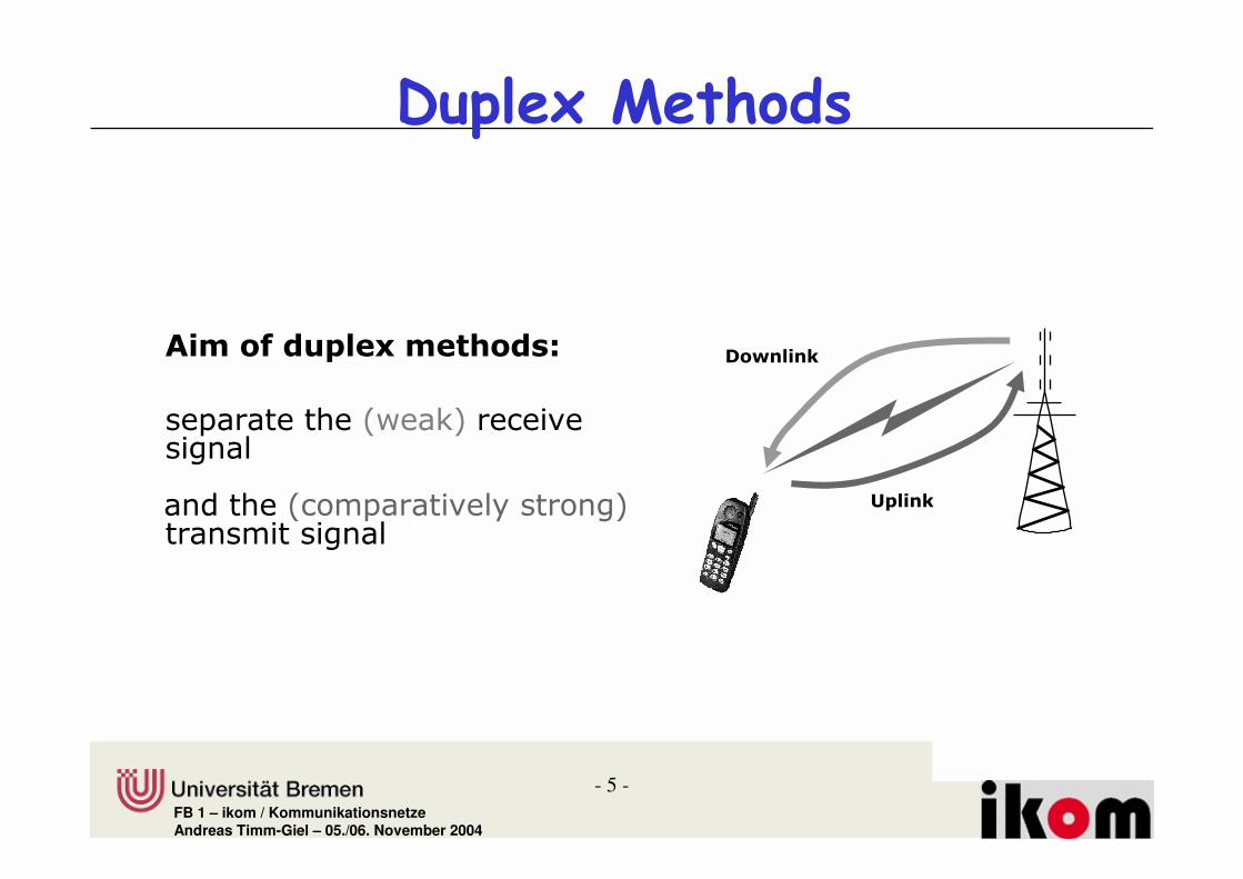
������ ��� �
!������ �� ��������� �� ���� �����"
#�!#�� � �����"
���������� ���
- 5 -FB 1 – ikom / KommunikationsnetzeAndreas Timm-Giel – 05./06. November 2004
� ������� �����
�� �$�%&� '�� ����(
��������������� �� ���������
������ ��������������������� �����
�&����
��������

- 6 -FB 1 – ikom / KommunikationsnetzeAndreas Timm-Giel – 05./06. November 2004
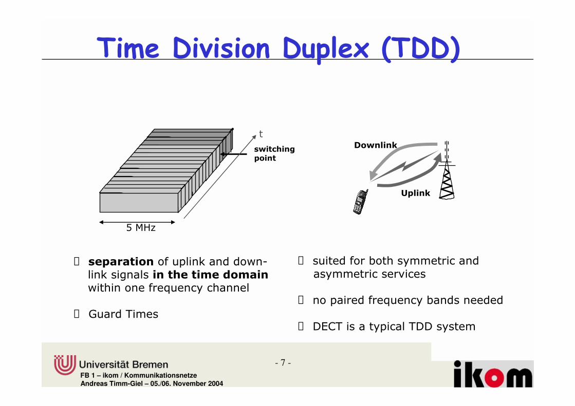
������ ���� ��� �� ��������� � �
� � &�� �$� )% ��������������� ���������������
� ������������������ �� ��� ���������
%&� '*�&���+
� ��������������� ����� �� ��!�!����� �������� ����� ��
� ���������"�� �#��� �����"�����
� $%���� ����&��
�&����
����� #��
,��-.
,��-.
������ #����������
- 7 -FB 1 – ikom / KommunikationsnetzeAndreas Timm-Giel – 05./06. November 2004
�� ��� ��� �� ��������� � �
� � &������������������������������� ����� ��� ��������������"�� � ����
� $����'����
� ��������#��������� ����������� ����� ��
� �����������"�� �#��� �����
� �()'��� ����� ��'��������
��������+�&����
*��+,
�&����
��������

- 8 -FB 1 – ikom / KommunikationsnetzeAndreas Timm-Giel – 05./06. November 2004
� ��������������� �����
-���������- ��������������� ������������� �������������#����� ����� ���� ���������������"�� ���� ���!
-���������- ��������������� ����������������
���������� �������������#����� ����� ���� ���������������"�� ���� ���!
���� �� ������#������������������� ����������������� ������#����� �� ���
%���.���/�∆� 0����1�23%45�
- 9 -FB 1 – ikom / KommunikationsnetzeAndreas Timm-Giel – 05./06. November 2004
� �������� ������
'����������������� ������������������"�� �#�������#�!
'����������������� ������������������"�� �#�������#�!
'����������#�#������ ��������������������������������������%45!
'����������#�#������ ��������������������������������������%45!
'��������� � �����#���������� ���������� ������.
)�/� # 0����1�23%45�)�/� # 0����1�23%45� 6#�4�7
����� ���� %45�882 �������������������.
)�����249�0�#�0�%45�:)�����249�0�#�0�%45�:
- 10 -FB 1 – ikom / KommunikationsnetzeAndreas Timm-Giel – 05./06. November 2004
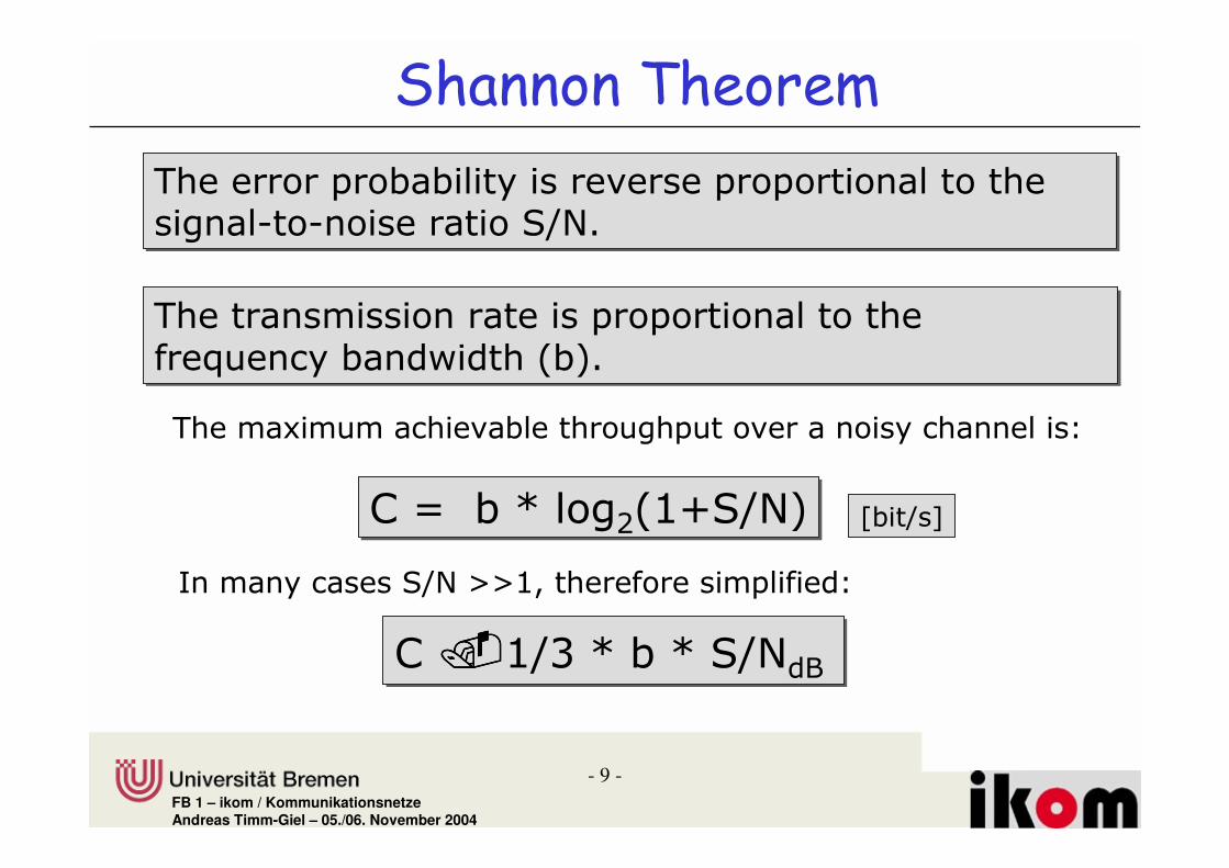
������������������� ������ • Bandwidth and S/N are reciproke to each other• Means:
– With low bandwidth very high data rate is possible provided S/N is high enough
• Example: higher order modulation schemes– With high noise (low S/N) data communication
is possible if bandwidth is high enough• Example: spread spectrum….
– Long time Capacity as theoretical limit, since turbo coding (1993) practical systems with 0.5 dB to Shannon channel bandwidth…

- 11 -FB 1 – ikom / KommunikationsnetzeAndreas Timm-Giel – 05./06. November 2004
/� )% ������0�������%���&� � �� ��
�� ��� ���
#� ���0�������%���&� � �� ��
�� ��� ���
f
t
p t( )
t
T0
p t( )
t
T0
p t( )
t
0 T
�
���+����� ��
�+�������� ��1�!�!�$%��
�+�������� �� �!�!��%�;*
)�����2
)�����1
)�����9
��� ���0�������%���&� � �� ��
�� ��� ���

- 12 -FB 1 – ikom / KommunikationsnetzeAndreas Timm-Giel – 05./06. November 2004
• Energy necessary for the transmission of a bit is independent on the multiple access technique.– FDMA signal transmitted in a frequency channel
with no time limitation– TDMA signal with same energy is transmitted
over a wider bandwidth and shorter time– CDMA distributes power of wider bandwidth and
full time, power density is lower

- 13 -FB 1 – ikom / KommunikationsnetzeAndreas Timm-Giel – 05./06. November 2004
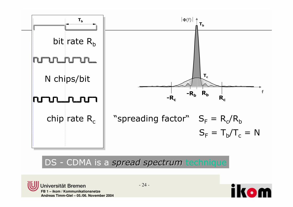
� ����� ���� ���!� � �������� ����������� ����� �#��������� �������� ��� �#���� �����"�� �� �����
������� ����������� ����� �#��������� �������� ��� �#���� �����"�� �� �����
-������������� �����������������������"�� � ����
-������������� �����������������������"�� � ����
����������������%45�<�2
(� ������ ������������#��������&�! '��#� �����#� ���� �� ��������!
(� ��������� ������������#��������&����&�! '��#� �����#� ���� �� ��������!
'������������������� #������:� ��������������� ����= ��!�!�:�8�=
���������������>��������>

- 14 -FB 1 – ikom / KommunikationsnetzeAndreas Timm-Giel – 05./06. November 2004
� �������! "�����
• In simple non-military applications: 10..100• In military applications: spreading factor up to 10
000

- 15 -FB 1 – ikom / KommunikationsnetzeAndreas Timm-Giel – 05./06. November 2004
����#$�!��%�������• Die Codes unterschiedlicher Teilnehmer sollen orthogonal
zueinander sein.• Die Codes sollen eine hohe Autokorrelation besitzen,sehr
gutes Beispiel Barker-Code:(+1,-1,+1,+1,-1+1,+1,+1,-1,-1,-1)
AKF(0)=11, AKF(1)=1; wird daher auch gerne zur Synchronisation verwendet

- 16 -FB 1 – ikom / KommunikationsnetzeAndreas Timm-Giel – 05./06. November 2004
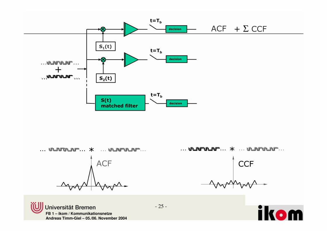
�& � ' #�������
• Much more complex than transmitter• Challenge: synchronisation when multiplying
received signal with codes sequence• Problem: multipath propagation• Therefore often Rake-Receivers are used, which
calculate for different delay (multipathcomponents) the product and compare it.

- 17 -FB 1 – ikom / KommunikationsnetzeAndreas Timm-Giel – 05./06. November 2004
�������� ����������� ���
2�����*2
�������� ����������� ���
�2
2�����*2
��� �������� ����� 32#��#��
��������� �����
��������� �����
���� ����

- 18 -FB 1 – ikom / KommunikationsnetzeAndreas Timm-Giel – 05./06. November 2004
�& � ' ����� �����• Sender A
– sends Ad = 1, key Ak = 010011 (assign: „0“= -1, „1“= +1)– sending signal As = Ad · Ak = (-1, +1, -1, -1, +1, +1)
• Sender B– sends Bd = 0, key Bk = 110101 (assign: „0“= -1, „1“= +1)– sending signal Bs = Bd · Bk = (-1, -1, +1, -1, +1, -1)
• Both signals superimpose in space – interference neglected (noise etc.)– As + Bs = (-2, 0, 0, -2, +2, 0)
• Receiver wants to receive signal from sender A– apply key Ak bitwise (inner product)
• Ae = (-2, 0, 0, -2, +2, 0) · Ak = 2 + 0 + 0 + 2 + 2 + 0 = 6• result greater than 0, therefore, original bit was „1“
– receiving B• Be = (-2, 0, 0, -2, +2, 0) · Bk = -2 + 0 + 0 - 2 - 2 + 0 = -6, i.e. „0“

- 19 -FB 1 – ikom / KommunikationsnetzeAndreas Timm-Giel – 05./06. November 2004
�& � ' ����%�!����������data A
key A
signal A
data ⊕ key
keysequence A
Real systems use much longer keys resulting in a larger distancebetween single code words in code space.
1 0 1
10 0 1 0 0 1 0 0 0 1 0 1 1 0 0 1 1
01 1 0 1 1 1 0 0 0 1 0 0 0 1 1 0 0
Ad
Ak
As

- 20 -FB 1 – ikom / KommunikationsnetzeAndreas Timm-Giel – 05./06. November 2004
�& � ' ����%�!�����������
signal A
data B
key Bkey
sequence B
signal B
As + Bs
data ⊕ key
1 0 0
00 0 1 1 0 1 0 1 0 0 0 0 1 0 1 1 1
11 1 0 0 1 1 0 1 0 0 0 0 1 0 1 1 1
Bd
Bk
Bs
As

- 21 -FB 1 – ikom / KommunikationsnetzeAndreas Timm-Giel – 05./06. November 2004
�& � ' ����%�!������������
Ak
(As + Bs) * Ak
integratoroutput
comparatoroutput
As + Bs
data A
1 0 1
1 0 1 Ad

- 22 -FB 1 – ikom / KommunikationsnetzeAndreas Timm-Giel – 05./06. November 2004
�& � ' ����%�!����������(
integratoroutput
comparatoroutput
Bk
(As + Bs) * Bk
As + Bs
data B
1 0 0
1 0 0 Bd

- 23 -FB 1 – ikom / KommunikationsnetzeAndreas Timm-Giel – 05./06. November 2004
comparatoroutput
�& � ' ����%�!���������(
wrongkey K
integratoroutput
(As + Bs) * K
As + Bs
(0) (0) ?
- 24 -FB 1 – ikom / KommunikationsnetzeAndreas Timm-Giel – 05./06. November 2004
$
>���������� ��> %& /�? 4?#
%& /�'#4' /�5
#� ����?#
5� ����4#�
*�� ��
����
��
ΦΦΦΦ���
��
�������?
*�� ��
�%�� )��-��� � ������������ � ��"���%�� )��-��� � ������������������������ � ��"��
- 25 -FB 1 – ikom / KommunikationsnetzeAndreas Timm-Giel – 05./06. November 2004
!!!!!! !!!!!!!!!
!!! !!!
3
0!!! !!! !!! !!!
-)&
-)&
�2!�"
�3��
������
�3��
�������!�"����� $��� �
�4!�"
�3��
������
))&
0 !!! !!!!!! !!!
3�Σ ))&

- 26 -FB 1 – ikom / KommunikationsnetzeAndreas Timm-Giel – 05./06. November 2004
$*���� $*�� ��
$*����*�� ��
$*�� ��
$*����*�� ��
��� ���
������� �
ΦΦΦΦ��� ΦΦΦΦ��� ΦΦΦΦ���
ΦΦΦΦ���ΦΦΦΦ���
5
5�
>��� ��������>
$@ /�A4A� /�%&

- 27 -FB 1 – ikom / KommunikationsnetzeAndreas Timm-Giel – 05./06. November 2004
(#
5B
%��:5��?
!/%��5��
!/ $@
�����������
��� ���
����#�����
'��(#45B �� $@ ���� ����������%45
" ��#��#$ ��� ����

- 28 -FB 1 – ikom / KommunikationsnetzeAndreas Timm-Giel – 05./06. November 2004
$
$
$
$
���������
������������� �
���������������������
�����
�
�� ���
�
��� � ���
�����
���������
����������
�� ���
�� ���
f
- 29 -FB 1 – ikom / KommunikationsnetzeAndreas Timm-Giel – 05./06. November 2004
33
�&� ��+�� 4
�&� ��+�� 2
����%������ �������!����� � � �
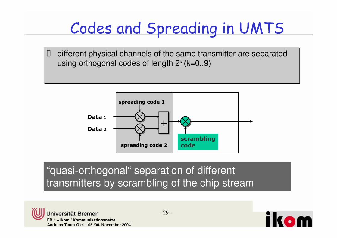
� different physical channels of the same transmitter are separated using orthogonal codes of length 2k (k=0..9)
� different physical channels of the same transmitter are separated using orthogonal codesorthogonal codes of length 2k (k=0..9)
��2
��4
��������+��
“quasi-orthogonal“ separation of different transmitters by scrambling of the chip stream

- 30 -FB 1 – ikom / KommunikationsnetzeAndreas Timm-Giel – 05./06. November 2004
% & ��' % ����"� ���& ���(��� ���� "�!���
#� ����?#2
52 ����4#�
��
��
�������?
#� ����?#1
51 ����4#�
��
��
�������?
#� ����?#9
59 ����4#�
��
��
�������?
- 31 -FB 1 – ikom / KommunikationsnetzeAndreas Timm-Giel – 05./06. November 2004
%&�/�2
%&�/�1
%&�/�C
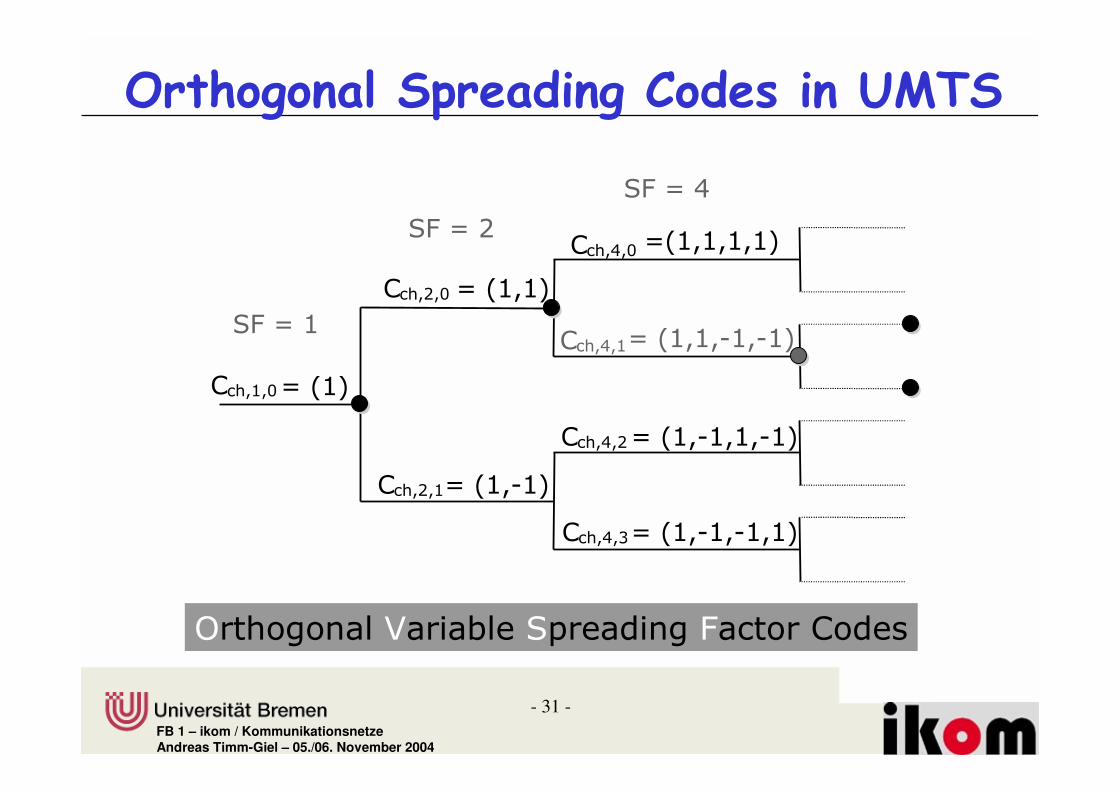
) � 2 B/��2�
) � 1 B /��2 2�
) � 1 2�/��2 �2�
) � C B�/�2 2 2 2�
) � C 2�/��2 2 �2 �2�
) � C 1�/��2 �2 2 �2�
) � C 9�/��2 �2 �2 2�
D�������E����#���%�������&� ��)����
% ����"� ��� ���� " !���� ��� �

- 32 -FB 1 – ikom / KommunikationsnetzeAndreas Timm-Giel – 05./06. November 2004
� ������ � ��� �
���(ωωωω t)
-���( ω ω ω ω t)
&������'�� ������ ���������.�6��76��7
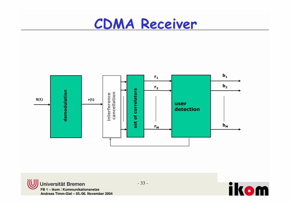
&%�� ��&��+
�����������������������**��� ��� #���� #���� �����
�������� �� ��α /�B!11
��8�9
� 8�9
������4����
�����
&%�� ��&��+
����� ������� ���� ����������������F@%G
�����"�� �1��9!FC�� ��!
- 33 -FB 1 – ikom / KommunikationsnetzeAndreas Timm-Giel – 05./06. November 2004
!� � ���������
%� � � �����
�2
�4
��
�!�" �!�"
��%�����
��� �$ � ��
��� ������
�2
�4
��� ��$����� �����

- 34 -FB 1 – ikom / KommunikationsnetzeAndreas Timm-Giel – 05./06. November 2004
)��-��� �����)��-��� �����
������������ �������������� �������������� �������������� ��
������������ ��#���������#�������
H�� ��� ��H�� ��� �� ������� � � ������������� � � ������
�� �������� ����������������������
��������I���������%�"�� ���� ����I%�
��������I���������%�"�� ���� ����I%�
�� ����������� ��
�� ����������� ��
���������%"�����(�������� �����%(�
���������%"�����(�������� �����%(�

- 35 -FB 1 – ikom / KommunikationsnetzeAndreas Timm-Giel – 05./06. November 2004
:�ΣΣΣΣ� �� ##/
$ ���#����)�����
�2!�"
�3��
;����� � �
!!! !!!
!!! !!!3 � #/
��������- ����������� ���-��
�-���� ��������� ������ ��� #� ���������
���� ���������������� �����������#������������������������
����:(?�������������

- 36 -FB 1 – ikom / KommunikationsnetzeAndreas Timm-Giel – 05./06. November 2004
:(?
2BB
2B�2
2B�1
2B�9
2B�C
2B�*
B * 2B 2* 1B 1* 9B
(#45B 6�:7
)%�� � �0 &�� ��
� � ��%� �1�<$�<
�����+ ��%� �1<� �<
���+� %� ���%�
=���;���������������$�� ���+� ��� ��� � ������������ � � �0 ��� �� !>=����?=���$$ � �� "
2B������

FB 1 – ikom / Kommunikationsnetze
����������)
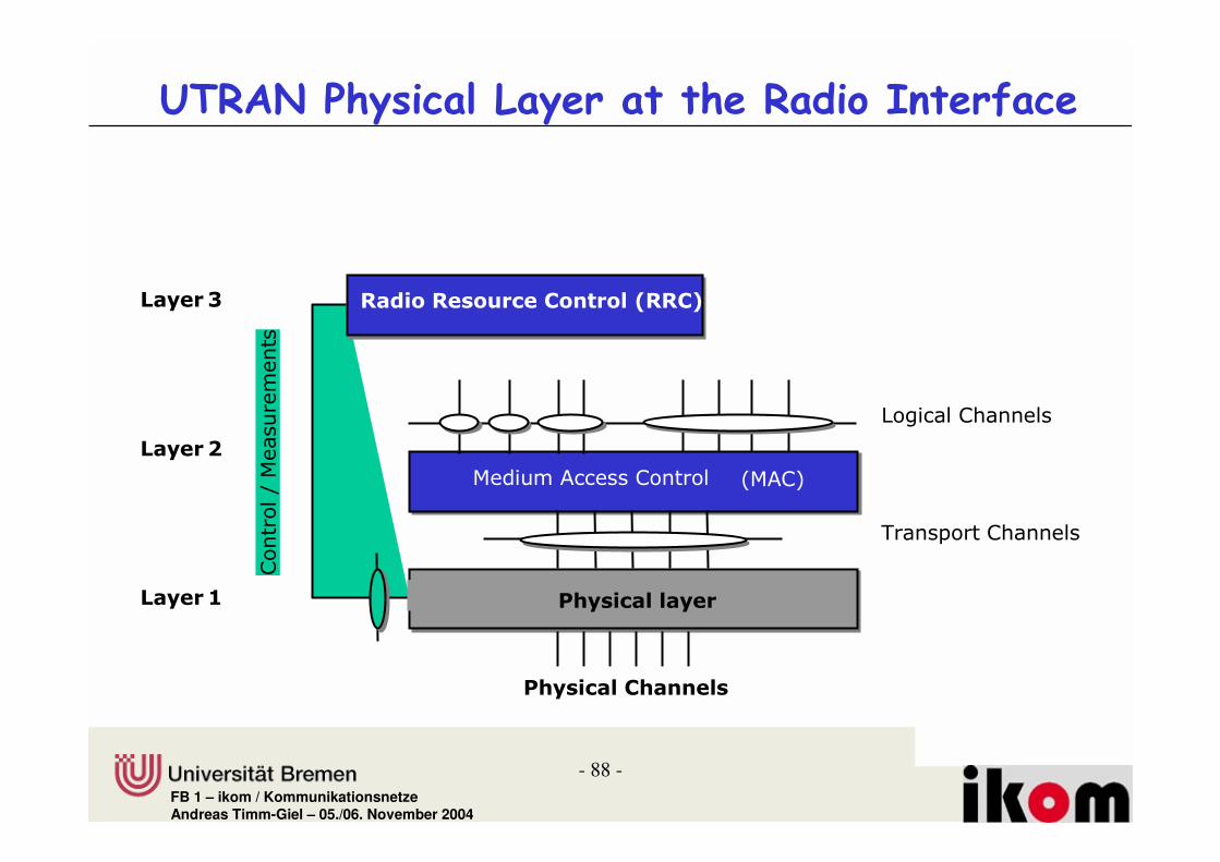
Protocol Stack at Radio Interface

- 38 -FB 1 – ikom / KommunikationsnetzeAndreas Timm-Giel – 05./06. November 2004
�� * � ������������� ����
@�������
%�����
��� I��
@���� ��
'������
5�����
-���� ���
%�
���-
%�
���:
@�������
%�����
��� I��
@���� ��
'������
5�����
-���� ���
��� I��
@���� ��
5�����
?����
���� �� �� ��

- 39 -FB 1 – ikom / KommunikationsnetzeAndreas Timm-Giel – 05./06. November 2004
+��������� ���,�' ��������-�����
��� I����� I��
5�����5�����
'���'?-����� ���� � ������������ � �������� ������ 2���9!
����� ������
���
���
)�����.
������ ��� �������
������.
������ ����������
������.
���� ���� ������ ���������
@���� ��@���� ��

- 40 -FB 1 – ikom / KommunikationsnetzeAndreas Timm-Giel – 05./06. November 2004
+��������� ���,�' ��������-������ #*&�� ���+�����+ �*&�� ���$�������
�-@ �2
����&����#��� ��
�4�� #� #
��#���#� �4���#�
����
��
��
�������
�������
��
��
�%&�������0����
�%� ��%���
�)5$)
��+���#��� ��
��# �4���#��#��#
��#��#
��#��#
��#
=�# �4�=�#
��#
I-J(?�1
I-J(?�9
�)5$)
- 41 -FB 1 – ikom / KommunikationsnetzeAndreas Timm-Giel – 05./06. November 2004
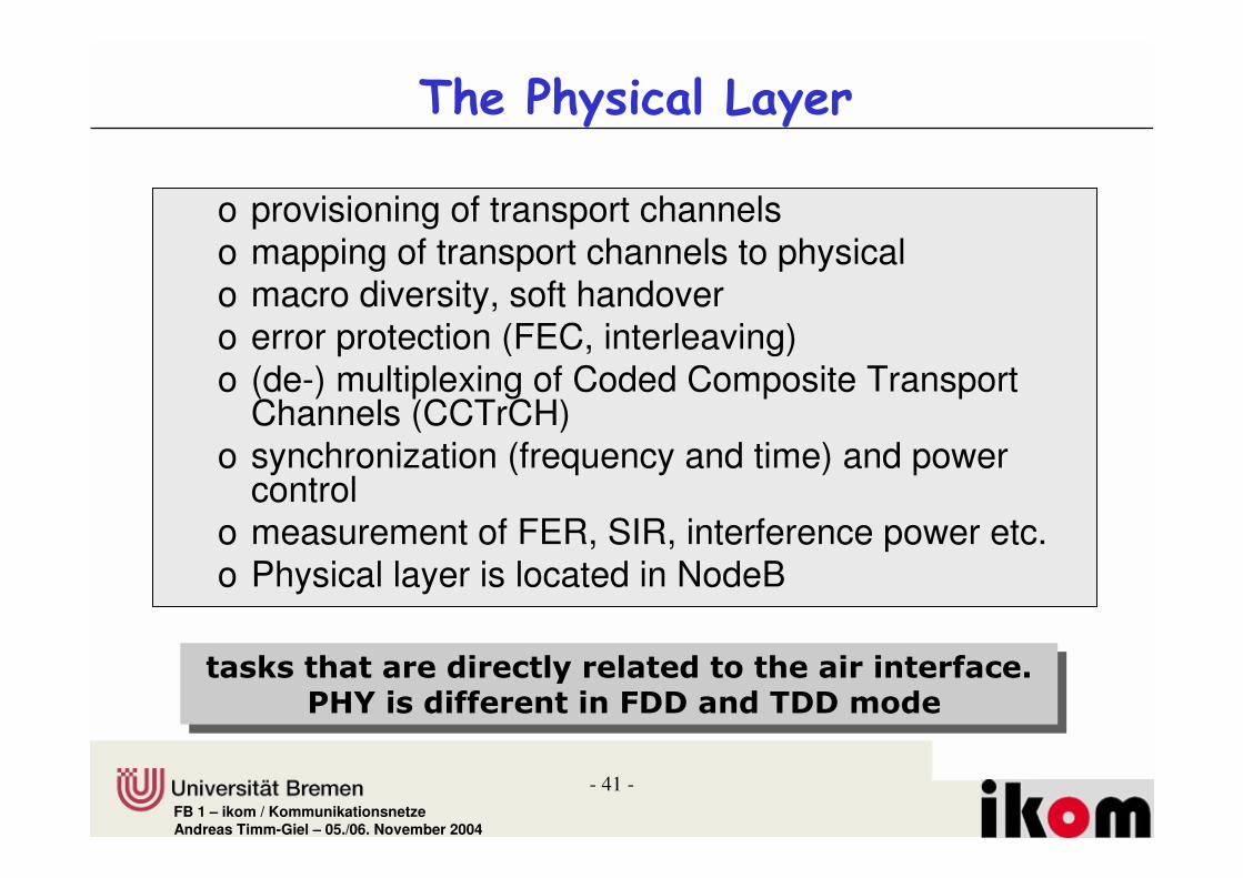
����*�������+����
o provisioning of transport channelso mapping of transport channels to physical o macro diversity, soft handovero error protection (FEC, interleaving) o (de-) multiplexing of Coded Composite Transport
Channels (CCTrCH)o synchronization (frequency and time) and power
controlo measurement of FER, SIR, interference power etc.o Physical layer is located in NodeB
���� ���� �� ����� �� ����� �� ��� �$� ��-@��� �$$ � ������/�����������
���� ���� �� ����� �� ����� �� ��� �$� ��-@��� �$$ � ������/�����������
- 42 -FB 1 – ikom / KommunikationsnetzeAndreas Timm-Giel – 05./06. November 2004
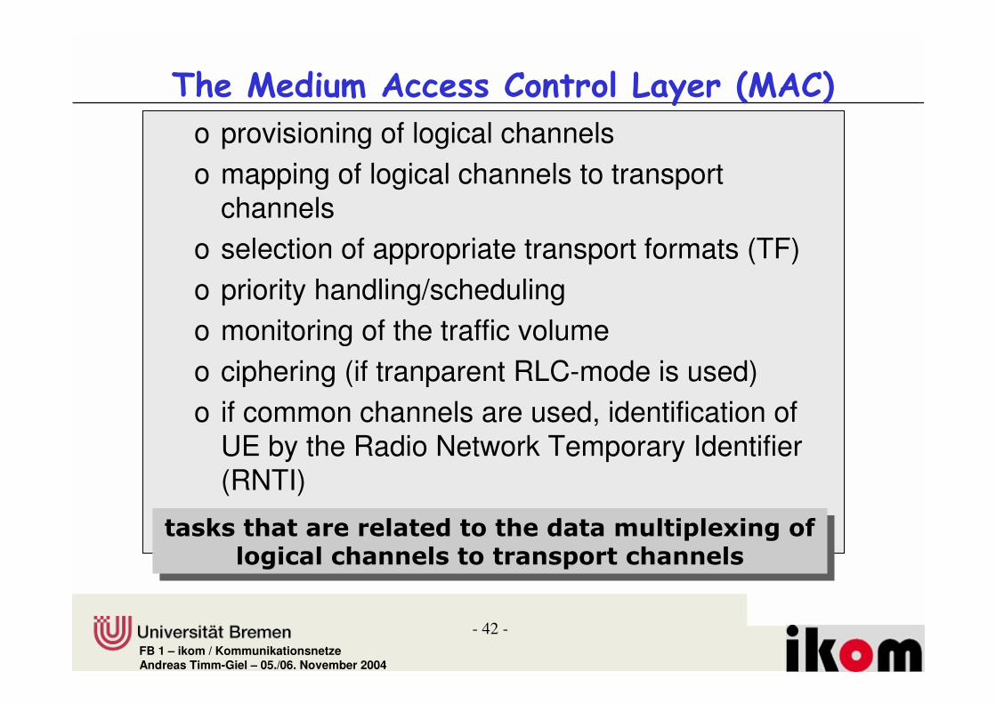
����� ��� ��������!� �����+������� �!�
o provisioning of logical channelso mapping of logical channels to transport
channels o selection of appropriate transport formats (TF) o priority handling/schedulingo monitoring of the traffic volumeo ciphering (if tranparent RLC-mode is used)o if common channels are used, identification of
UE by the Radio Network Temporary Identifier (RNTI)
o no segmentation of data!���� ���� � �� ����� ��%���&� '��+�$�
��+������� �� �������&������� ��
���� ���� � �� ����� ��%���&� '��+�$���+������� �� �������&������� ��

- 43 -FB 1 – ikom / KommunikationsnetzeAndreas Timm-Giel – 05./06. November 2004
��������+ ,�!� �����+�������+!�
o 3 transfer modes:o acknowledged mode transfer
(ARQ error handling, order, singleness)o unacknowledged mode transfer
(error-free, singleness, contemporary)o transparent mode transfer
(no error protection)o segmentation/reassemblyo flow controlo ciphering (only non-transparent services)
���� ���� � �� ����� &��� �� ������������$������ ���� � �� ����� &��� �� ������������$��

- 44 -FB 1 – ikom / KommunikationsnetzeAndreas Timm-Giel – 05./06. November 2004
����-�������.� ������� !� �����+������-� !�
o management of Cell-Broadcast-Messages (CBM)o control of service attributes for Cell-Broadcast-
Services (CBS) in the UTRANo transmission of CBM to higher layers for evaluation
���� �� �������������������� �������������� �������)����:���� �����������
���� �� �������������������� �������������� �������)����:���� �����������

- 45 -FB 1 – ikom / KommunikationsnetzeAndreas Timm-Giel – 05./06. November 2004
*��,���� ����!� ���"� ���*��������+������*� !*�
o Alignment of RLC-services to packet data protocols like TCP/IP
o Header compression
���� �� ������������������� ������'?-����� ���� � �������� ������ ���� ��� ����')@4�@
���� �� ������������������� ������'?-����� ���� � �������� ������ ���� ��� ����')@4�@

- 46 -FB 1 – ikom / KommunikationsnetzeAndreas Timm-Giel – 05./06. November 2004
�����������������!� �����+��������!�
o broadcast of system informationso set-up and management of Radio Bearerso mobility management
o location managemento handover
o outer loop power controlo configuration of lower layerso collection of measurements from lower layers
���� �� ������������� ��������� ��������������������'?-����� ���� � ����
�������� �
���� �� ������������� ��������� ��������������������'?-����� ���� � ����
�������� �

- 47 -FB 1 – ikom / KommunikationsnetzeAndreas Timm-Giel – 05./06. November 2004
���� �����
��� ����� !�� ������������ �
?-)+.� ?���� - ����)������I� ����� � ��� ��������� �� ���
�%)+. ���������������%�����)����4�%)+.� ������#��������#���������� ������
���������
@)+.� @����)������I� �������� �������� ������#������
:)+.� :���� �� )������I� #���� �� �������� ��������
�)+.� ���� ���)������I4�I� ���� ������ ���������

- 48 -FB 1 – ikom / KommunikationsnetzeAndreas Timm-Giel – 05./06. November 2004
��� ������-���,�
�)+2 '�������:�� �
�)+9 '�������:�� � '�������:�� �'���!:!
�)+1 '�������:�� �
'�������:�� �
'�������:�� �
'�������:�� �
'���!:!
'���!:!
'�������:�� �
'�������:�� �
'�������:�� �
'�������:�� �
'�������:�� � '�������:�� �
'�������:�� �
'�������:�� �
'�������:�� ��%�
'����������'�����������''��
'����������'�����������''��
'����������'�����������''��

- 49 -FB 1 – ikom / KommunikationsnetzeAndreas Timm-Giel – 05./06. November 2004
��� ���������� ���
�)+2
':�%�,�':%�%�,� �''�
��������� �� �������
)?)� !
'?-5%@D?'&D?�-'
':�%�,�':%�%�,� �''�
��������� �� �������
)?)� !
'?-5%@D?'&D?�-'
':�%�,�':%�%�,� �''�
��������� �� �������
)?)� !
'?-5%@D?'&D?�-'
':�%�,�':%�%�,� �''�
��������� �� �������
)?)� !
'?-5%@D?'&D?�-'
'?-5%@D?'�&D?�-'�%('
'�������:�� �
'�������:�� �
'�������:�� �
'�������:�� �
'�������:�� �
'�������:�� � '�������:�� �
'�������:�� �
'�������:�� �
'����������'�����������''��

- 50 -FB 1 – ikom / KommunikationsnetzeAndreas Timm-Giel – 05./06. November 2004
��� ���������� ���!�� ( ��� �
�)+2 �)+1 �)+9
'?-5%@D?'&D?�-'
'�������&�����%��� �� #���#������� ��#����� ���))'�)+K� ��� ���� ������!�
'�������&�����%��� �� #���#������� ��#����� ���))'�)+K� ��� ���� ������!�
'?-5%@D?'&D?�-'
'?-5%@D?'&D?�-'
'?-5%@D?'&D?�-'
'?-5%@D?'&D?�-'
'?-5%@D?'&D?�-'
'?-5%�@D?'
&D?�-'
'?-5%�@D?'
&D?�-'
'?-5%�@D?'
&D?�-'

- 51 -FB 1 – ikom / KommunikationsnetzeAndreas Timm-Giel – 05./06. November 2004
��� ���������� ���!�� ( ��� � ���
�)+2 �)+1 �)+9
'?-5%@D?'
&D?�-'
'?-5%@D?'
&D?�-'
'&)%�����������'&)� �#�������� ��!�!������������� ��� �� �#�������#���������� �����!
'&)%�����������'&)� �#�������� ��!�!������������� ��� �� �#�������#���������� �����!
'&)%
'?-5%@D?'
&D?�-'
'?-5%@D?'
&D?�-'
'?-5%@D?'&D?�-'
'?-5%@D?'&D?�-'
'?-5%@D?'&D?�-'
'?-5%@D?'
&D?�-'
'?-5%@D?'&D?�-'
'?-5%@D?'
&D?�-'
'?-5%@D?'&D?�-'
'?-5%@D?'
&D?�-'
':�%�,�':%�%�,�
��������� �� �������
)?)� !
'?-5%@D?'
&D?�-'
'?-5%@D?'
&D?�-'
'?-5%@D?'
&D?�-'
'?-5%@D?'&D?�-'
':�%�,�':%�%�,�
��������� �� �������
)?)� !
':�%�,�':%�%�,�
��������� �� �������
)?)� !
':�%�,�':%�%�,�
��������� �� �������
)?)� !
':�%�,�':%�%�,�
��������� �� �������
)?)� ! ':�%�,�
':%�%�,���������� ��
�������)?)
� !
':�%�,�':%�%�,�
��������� �� �������
)?)� !
':�%�,�':%�%�,�
��������� �� �������
)?)� !
':�%�,�':%�%�,�
��������� �� �������
)?)� !
':�%�,�':%�%�,�
��������� �� �������
)?)� !
':�%�,�':%�%�,�
��������� �� �������
)?)� !
':�%�,�':%�%�,�
��������� �� �������
)?)� !
':�%�,�':%�%�,�
��������� �� �������
)?)� !
':�%�,�':%�%�,�
��������� �� �������
)?)� !
':�%�,�':%�%�,�
��������� �� �������
)?)� !
':�%�,�':%�%�,�
��������� �� �������
)?)� !
':�%�,�':%�%�,�
��������� �� �������
)?)� !
':�%�,�':%�%�,�
��������� �� �������
)?)� !
'?-5%@D?'
&D?�-'
'?-5%@D?'&D?�-'
- 52 -FB 1 – ikom / KommunikationsnetzeAndreas Timm-Giel – 05./06. November 2004
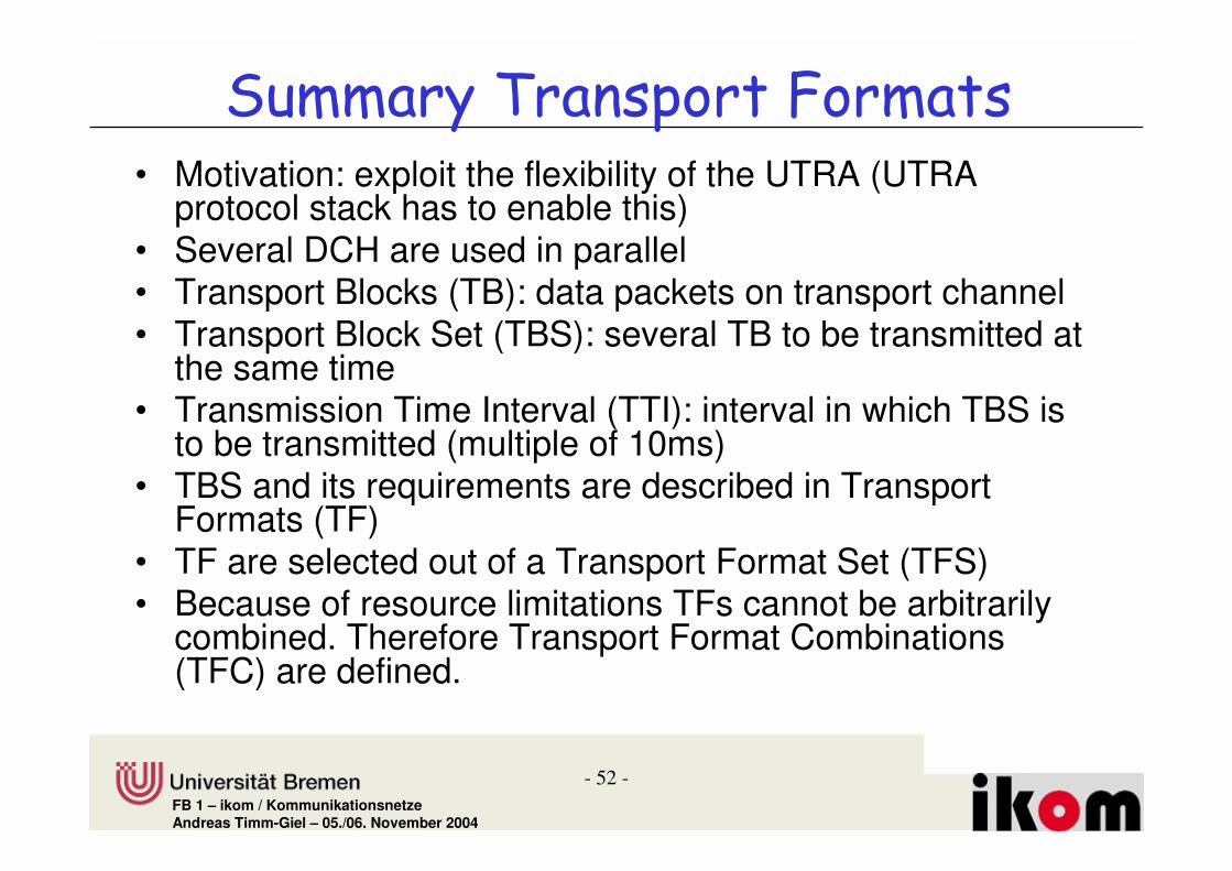
� -� � ����� ���%�����"��� ��%• Motivation: exploit the flexibility of the UTRA (UTRA
protocol stack has to enable this)• Several DCH are used in parallel• Transport Blocks (TB): data packets on transport channel• Transport Block Set (TBS): several TB to be transmitted at
the same time• Transmission Time Interval (TTI): interval in which TBS is
to be transmitted (multiple of 10ms)• TBS and its requirements are described in Transport
Formats (TF)• TF are selected out of a Transport Format Set (TFS)• Because of resource limitations TFs cannot be arbitrarily
combined. Therefore Transport Format Combinations (TFC) are defined.
- 53 -FB 1 – ikom / KommunikationsnetzeAndreas Timm-Giel – 05./06. November 2004
� ���%�����"��� ��%.�"-�����������
• At connection set-up RRC specifies TFC for connection
• MAC can dynamically distribute the capacity between different transport channels considering actual data volume in the individual channels
• MAC signals its selection via the Transport Format Combination Identifier (TFCI) to the physical layer. TFCI is transmitted to other end and used for demultiplexing.

- 54 -FB 1 – ikom / KommunikationsnetzeAndreas Timm-Giel – 05./06. November 2004
� ' �#/����
o Segmentation of PDUs received from RLC over logical channels to transport blocks that may belong to different transport channels (downstreams)
o Reassembly and mapping of received TBS to logical channels (upstream)
o Scheduling, priority handling
o Reporting of achieved throughput, used TFCS etc. to the RRC Layer

- 55 -FB 1 – ikom / KommunikationsnetzeAndreas Timm-Giel – 05./06. November 2004
/�!������������%��%��������
�')+.� ���� ���'����� )�����������������������
)))+. )�����)����)���������������� �������
�))+.� ���� ���)����)���������������� �� ��������� ����
���
:))+.� :���� �� )����)����#���� �� �������� ��������
Content is important for logical channels

- 56 -FB 1 – ikom / KommunikationsnetzeAndreas Timm-Giel – 05./06. November 2004
� ��� "����+�"���������� ������!�� ����/01
• User data channel DTCH (dedicated traffic channel) and the signalling channel DCCH (dedicated control channel) can be transmitted over several transport channels:– Dedicated transport channel, DCH– Small data packets can be transmitted efficiently and without
complicated signalling via Random Access Channel (RACH) in the uplink and Forward Access Channel (FACH) in the downlink
– Jointly used channels (Downlink Shared Channel DSCH, Uplink Shared Channel USCH, Common Packet Channel CPCH (uplink)
• CCCH is used for signalling outside an existing connection and is transmitted over transport channels RACH (Random Access Channel) and FACH (Forward Access Channel)

- 57 -FB 1 – ikom / KommunikationsnetzeAndreas Timm-Giel – 05./06. November 2004
� ��� "���+�"����!�� ���������� ������!�� ����101
=#- �#- ��#-/ #-� #- �#-
=##- �##- ###-�##- ��#-
����&���#��� ��
� #�� ��
��#-!���"
#�#-!/��"
�'?-5������'?-5�����

FB 1 – ikom / Kommunikationsnetze
����������0
UMTS Air Interface Physical Layer at Radio Interface

- 59 -FB 1 – ikom / KommunikationsnetzeAndreas Timm-Giel – 05./06. November 2004
����$ �*�������+����������������� �������
����� ��%�� #������!��#"
� �%�� �� ���#������!� #"
'�������)�����
��������� �
)��
��4�
�������
���
�� �?
I��� ��)�����
�� �4
�� �2
�������#��� ��

- 60 -FB 1 – ikom / KommunikationsnetzeAndreas Timm-Giel – 05./06. November 2004
+��%�����/����– Provides transport services to MAC– Error protection and correction– Measurement of transmission channel characteristics– Reporting of measurement results to RRC layer– Duplication and merging of data streams for soft
handover– Spreading and modulation– Power control and synchronisation– Maps transport channels to physical channels

- 61 -FB 1 – ikom / KommunikationsnetzeAndreas Timm-Giel – 05./06. November 2004
� ���%������������%– Physical channels are distinguished by parameters like
spreading codes– Data of different transport channels can be transmitted
simultaneously over one physical channel– Each transport channel is allocated a transport format or
set of transport formats, that define the mapping– Transport format defines specifically channel coding,
interleaving and bit rate– Transport formats are determined by the Radio
Resource Control (RRC) layer

- 62 -FB 1 – ikom / KommunikationsnetzeAndreas Timm-Giel – 05./06. November 2004
+�����-��%��������+��%�����/����
@���� ��)�����
� �%�� �� ���#������ !� #"
'�������)�����
@���� �������
#���+1��� �� 0��+
���
����������
%�������
#���+1���� �� 0��+
���
#���+1��� �� 0��+
���
#���+1��� �� 0��+
���
#���+1��� �� 0��+
���
)����)�������'�������)����))'�)+))'�)+

- 63 -FB 1 – ikom / KommunikationsnetzeAndreas Timm-Giel – 05./06. November 2004
��������� ��%����� ���%������������
• Transport blocks requiring same coding, interleaving, puncturing in the physical layer can be multiplexed into one Coded Composite Transport Channel
• Only one CCTrCH is allowed in the uplink, i.e. transport blocks of different transport channels are transmitted at the same time, with the same channel coding…
• With this approach transmission capacity of physical channel can be changed every 10ms

- 64 -FB 1 – ikom / KommunikationsnetzeAndreas Timm-Giel – 05./06. November 2004
� -�������' ���%%• UMTS-TDD and UMTS-FDD use different duplex and
different multiple access techniques• UMTS-TDD and UMTS-FDD differ in physical layer of
UTRA protocol stack. All other protocols and system components are nearly the same.
• Both use the same time scheme with frames of 10ms duration, equalling 38400 chips.
• Each frame is divided into 15 time slots, corresponding to 2560 chips. Chip duration ~ 0.2604 µs

- 65 -FB 1 – ikom / KommunikationsnetzeAndreas Timm-Giel – 05./06. November 2004
� �������������
���$�� A� ���$�� A�:2
?BC>>����&≡≡≡≡ 2>��
��� �����!4,D>����&≅≅≅≅ DDD1D�µµµµ�"
������������.�9!FC�� ���4�)����������.���≅≅≅≅ B!1LBC�µ�
���$��
�%�*$�� �%�*$��
��� ����A> ��� ����A2 ��� ����A4 ��� ����A2? ��� ����A2C
!!!
24B>>����&≡≡≡≡ 2>��
2!1F�� ���4�≅≅≅≅ B!MF2�µ�
'������ �����������&������'��
E���� ������

- 66 -FB 1 – ikom / KommunikationsnetzeAndreas Timm-Giel – 05./06. November 2004
"& & �� �����1 #�& � '
2*����� 2*�����
/�2B��� /�2B���
*��+, 9!FC�� ���4�
�%���&� ��� ���� ���� )��-4&��-�
%&� '�� ���� &���
/�� ����� ���&���+� C!C��+,�N�*��+,�
��� �$�� �%������ 2B����
������$�� ���� 2*�
������$�� ���� 2*�
+������������������� �� 9!FC�� ���4��
��%������ O@%G�
�&� ��+�$�������� C�1*L�
�&� ��+�$�������� C�*21�
%��� ���� ���������� �� ����� #� ��������"������������,�������� �� ������������ ����

- 67 -FB 1 – ikom / KommunikationsnetzeAndreas Timm-Giel – 05./06. November 2004
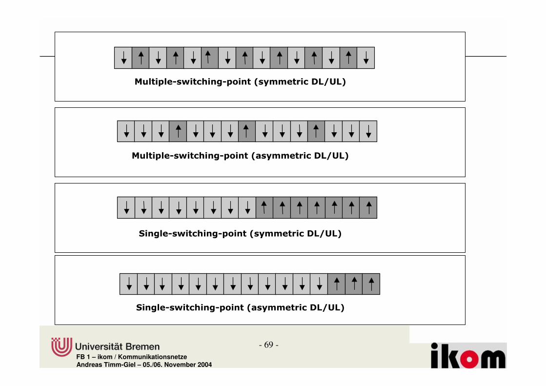
� & & �� ���• TDD; each time frame contains at least one time
slot for the uplink and one time slot for the downlink
• Only spreading factors between 1 and 16 are used resulting in the same transmission rates as in FDD
• As in FDD FDMA can be used if a Network operators provides of further frequency channels
• Switching points could be after each time slot, this would also minimize transmission delay, puts however high demands on hardware in Node B and ME.

- 68 -FB 1 – ikom / KommunikationsnetzeAndreas Timm-Giel – 05./06. November 2004
� & & �� ������ & #�& � '
�%���&� ��� ���� ���� )��-4&��-4'��-�
%&� '�� ���� '���
/�� ����� ���&���+� C!C��+,�N�*��+,�
��� �$�� �%������ 2B����
������$�� ���� 2�2C�����2*��
������$�� ���� 2�2C�����2*��
+������������������� � 9!FC�� ���4��
��%������ O@%G�
�&� ��+�$�������� 2�2L�
�&� ��+�$�������� 2����2L�
�I �I�I �I
*�+,
2*�%��� 2*�%���
- 69 -FB 1 – ikom / KommunikationsnetzeAndreas Timm-Giel – 05./06. November 2004
�%���&� *��������+*&����!���� ���� �����"
���+� *��������+*&����!���� ���� �����"
�%���&� *��������+*&����!���� ���� �����"
���+� *��������+*&����!���� ���� �����"

- 70 -FB 1 – ikom / KommunikationsnetzeAndreas Timm-Giel – 05./06. November 2004
� & & �� ���.�/�� ����������� �����• In Release 4 a low chip rate option is standardised with a
modulation rate of 1.28 Mchip/s.• 10 ms time frame is divided into 2 five ms sub-frames with
7 traffic slots each. Between the first and the second time slot of a sub-frame two synchronisation slots Downlink Pilot Tone Slot and Uplink Pilot Tone Slot and a guard period are located.
• The 1st time slot of each sub-frame is always allocated to the downlink, the 2nd always UL. The second switching point can be arbitrarily chosen from remaining time slot boundaries.
• As more than one frequency channel is used per operator, low chip rate TDD comprises FDMA with carrier spacing of 1.6 MHz

- 71 -FB 1 – ikom / KommunikationsnetzeAndreas Timm-Giel – 05./06. November 2004
� & & �� ���2���� �����������������
�%���&� ��� ���� ���� )��-4&��-4'��-�
�%&� '�� ���� '���
/�� ����� ���&���+� 2!L��+,��
��� �$�� �%������ 2B����
��� ��%�*$�� �%������ *����
��� �������%�*$�� ���� 2�L�����M��
��� �������%�*$�� ���� 2�L�����M��
��%�������� � 2!1F�� ���4��
��%������ O@%G����F@%G�
�&� ��+�$�������� 2�2L�
�&� ��+�$�������� 2����2L�
*������#������*������#������
2B����'��-������
2!L��+,
�I �I �I �I�I �I �I
��@'% ��@'%
�����������

- 72 -FB 1 – ikom / KommunikationsnetzeAndreas Timm-Giel – 05./06. November 2004
"& & �+�� ����������• In CDMA Power Control is important to minimize
near-far-effect• Inner Loop: Power control command can be
transmitted in each time slot, i.e. 1500 commands are transmitted per second.
• Outer Loop: Power control on time basis of frame length, i.e. 10 ms intervals (@RNC), responsible for setting target values of inner loop.
• Power control is based on C/I. C/I can be obtained in CDMA systems easily by correlation of received signal with code.

- 73 -FB 1 – ikom / KommunikationsnetzeAndreas Timm-Giel – 05./06. November 2004
�� � �*�2 ���!� ����
�'?-5
�� �����
�������
'@)
)4��������������
)4��������������
@)���������@)���������
��H�������
��H�������
�
33
)3�
)4������)4������
��������
��������

- 74 -FB 1 – ikom / KommunikationsnetzeAndreas Timm-Giel – 05./06. November 2004
� & & �+�� ����������
• In TDD channel identified by code and time slot• Only part of transmission capacity of 10ms time
frame allocated to channel• Short codes with small spreading factors are
required for achieving high bit rates.• Short codes are rare, only few users can be
served - > receivers with joint detection are suitable, they are resistant to near-far-effects
• Fast power control in any case difficult for TDD, as no continuous transmission

- 75 -FB 1 – ikom / KommunikationsnetzeAndreas Timm-Giel – 05./06. November 2004
�� � �*�2 ���!� ������� !3 ���� ,�
�������������
��������
�
33
)3�
��������������
��������������
@)���������@)���������
��H�������
��H�������
�'?-5
�����"�������(�
���
�'?-5�'?-5
�����+ �#��

- 76 -FB 1 – ikom / KommunikationsnetzeAndreas Timm-Giel – 05./06. November 2004
�� � �*�2 ���!� ������� *!3 �� �2 � ,�
�
)4��������������
)4��������������
@)���������@)���������
��H�������
��H�������
33
)3�'@)
�(��?���(��?��
5����:��'��
5����:��'��
)4������)4������ �'?-5�'?-5
��������
��������

- 77 -FB 1 – ikom / KommunikationsnetzeAndreas Timm-Giel – 05./06. November 2004
!�� ���!� "4�� ������� "4�� ������� "�� �*�������!�� ���� ��� "
'�������)�����
@���� ��)�����
� �%�� �� ���#������ !� #"
@���� �������
)���� ���������
� !
����������
%�������
)���� ����������
� !
)���� ���������
� !
)���� ���������
� !
)���� ���������
� !
)����)�������'�������)�����))'�)+))'�)+

- 78 -FB 1 – ikom / KommunikationsnetzeAndreas Timm-Giel – 05./06. November 2004
@���� ��)�����
���� ���������
� !
����������
��������
���� ���������
� !
���� ���������
� !
���� ���������
� !
���� ���������
� !
���������������� ������������� �� ����� ��������#��
@���� ��I������&��������
���������������������� �������#����������� ���2B��
������ ������ ��������������� �����#��� ����������������� ��������
�������������������� ������� >�������������������� ���

- 79 -FB 1 – ikom / KommunikationsnetzeAndreas Timm-Giel – 05./06. November 2004
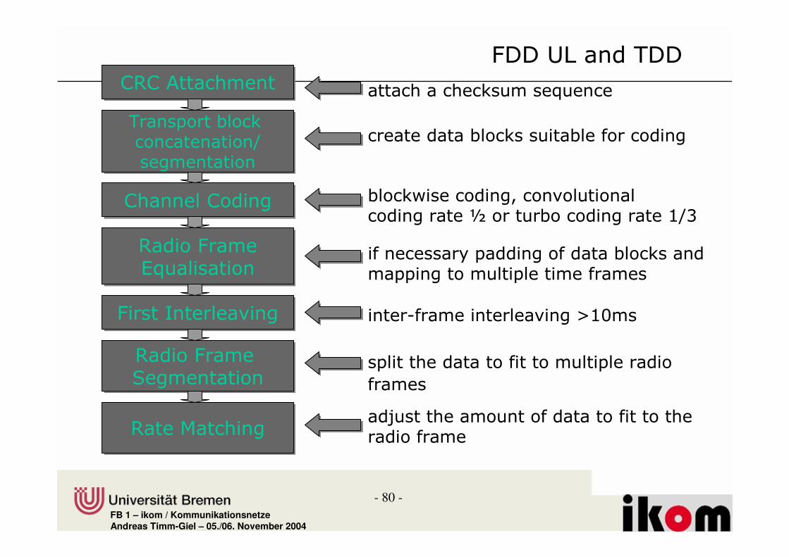
"& & *� /• Transmission capacity of transport channels is matched to
that of physical channels by puncturing and padding• Padding leads to transmission of at least a full time frame
and therefore audible interference are prevented• Each station uses a specific scrambling code in FDD,
therefore the entire family of OVSF codes is available to it• Spreading codes and spreading factor can therefore be
changed in short time intervals (how fast ???)• Aim to occupy as few as possible physical channels per
UE
- 80 -FB 1 – ikom / KommunikationsnetzeAndreas Timm-Giel – 05./06. November 2004
)?)�-� ���)?)�-� ��� �� ��� �� ���� ��"�� �
'�������#�� �� � �����4��������
'�������#�� �� � �����4��������
������� #�� �� ����#����� ����
)����)����)����)���� #�� ����� ���� � ��������� ��������P ����#� ��������249�
?�����&����("��������
?�����&����("��������
�� � ������������������ #�� �� ����������������������������
&�������������&������������� ������������������82B��
?�����&�����%�������
?�����&�����%�������
���� ����� ��������������������
������
?����� ���?����� �����H�� ������ ������ �������������������
&����I����'��

- 81 -FB 1 – ikom / KommunikationsnetzeAndreas Timm-Giel – 05./06. November 2004
"& & �& �� ����,• Audible interference no problem in FDD Downlink • because distance to Node B and number of simultaneously served
users• Usually one scrambling code is available per NodeB, therefore the
family of OVSF spreading codes is available only once• Spreading Code and Factor for a physical channel is changed at
intervals of more than 10ms based on negotiation by RRC• Rate matching function is also responsible to realise variable
transmission rates, if spreading factor cannot or not fast enough be changed
• Transmitter is switched of, when no data for this channel (muted):Technique is called Discontinuous Transmission (DTX)
• Generally a physical channel is not exclusively allocated to ONEtransport channel -> DTX is supported by insertion of DTX indicators in data stream.

- 82 -FB 1 – ikom / KommunikationsnetzeAndreas Timm-Giel – 05./06. November 2004
�������#������������������ �������� �� �����
���������������������� ��������#��������� �82B���
�����#������ ���� ��������#����� ����������������'Q
@���� ��I������&���������
����
���������� !
����������
��������
����
���������� !
����
���������� !
����
���������� !
����
���������� !
))'�)+))'�)+
&����I.�����������'Q���� ����� ����
����������'Q��� ���� ���������������������

- 83 -FB 1 – ikom / KommunikationsnetzeAndreas Timm-Giel – 05./06. November 2004
)?)�-� ���)?)�-� ��� �� ��� �� ���� ��"�� �
'�������#�� �� � �����4��������
'�������#�� �� � �����4��������
������� #�� ������#����� ����
)����)����)����)���� #�� ����� ���� � �������������#� ���� �����241���249�
?�����&�����%�������
?�����&�����%�������
���� ����� �������������������������
?����� ���?����� ��� ����������� ����������� ����������,������#����������������
&����I
�����������'Q��� ������
�����������'Q��� ������
��� �����������������'Q�� �����������������
&�������������&������������� ������������������82B��

- 84 -FB 1 – ikom / KommunikationsnetzeAndreas Timm-Giel – 05./06. November 2004
���� ���������
� !
����������
���� ���������
� !
���� ���������
� !
���� ���������
� !
���� ���������
� !
������������������������������������ ���������
@���� ��)�����
'������� �����
)����)�������'�������)�����))'�)+))'�)+
&����I.�����������'Q���� �������
&����I.�����������'Q���� �������
��������
• CCTrCH exists for each dedicated connection in the downlink
• Segmentation, 2nd interleaving as well as mapping to physical channels performed separately for each connection
• Dedicated physical channel therefore contains only transport blocks of one connection

- 85 -FB 1 – ikom / KommunikationsnetzeAndreas Timm-Giel – 05./06. November 2004
����� �� �����
))'�)+'�)+����������
?������������������
)���� ����
?����� ���
'�:� � �����4)����#�� ����������
)?)��� ���
?�����������"��������
2������������
������ �����
@���� �� ������������
1�����������
@���� �� ����������
))'�)+
2�����������
)���� ����
?������������������
'�:� � �����4)����#�� ����������
)?)��� ���
?����� ���
2������������'Q���!
'�)+����������
1������������'Q���!
������ �����
����� �� �����
'�
���
I4�
I��
��&
��
��I
&�
���
I
@���� �� ������������
1�����������
@���� �� ����������@���� �� ����������

- 86 -FB 1 – ikom / KommunikationsnetzeAndreas Timm-Giel – 05./06. November 2004
��� � � �#- �#-
����&����#��� ��%�� � 2� 1
����&����=�������. 1CC�#� 2BB�#�
����&����=������ ����. 1CC�#� 2BB�#�
��������������� ���� �0� 1B� �� CB� ��
��& ��$�;��������� ����� )�������)���� )�������)����
#���+�� 249 249
�� �������+�����%� 1*L 1*L
��. �$�#�# 2L�#� 21�#�
����������$���#-������$�� ����� �����
(������.�21!1��#�� ������ ��������� ��
��� � � ��� /��
��$����������� �F������G 21!1� 21!1=%��� ���2 &�����1��� �� 0��+ 1B��� 1B����/#� 2L�#�4���� ���##-�F������G 1� 2C����#-�F������G CF F LB�&� ��+$���� F LC�%���%���+�#-��##- *R�4�BR BR� & ������ BR 19R
@���� �������

FB 1 – ikom / Kommunikationsnetze
����������3�
Physical Channels and Procedures at the Air Interface
- 88 -FB 1 – ikom / KommunikationsnetzeAndreas Timm-Giel – 05./06. November 2004
����$ �*�������+����������������� �������
����� ��%�� #������!��#"
�������- ����)���� ��-)�
'�������)�����
��������� �
)��
��4�
�������
���
�� �?
I��� ��)�����
�� �4
�� �2
�������#��� ��

- 89 -FB 1 – ikom / KommunikationsnetzeAndreas Timm-Giel – 05./06. November 2004
+��%������������%
/��.��������� ��� ����"�� � ���� ���I.���������� ��� �����������
/��.��������� ��� ����"�� � ���� ���I.���������� ��� �����������
���.��������� ��� �������� �����"�� � ����
���.��������� ��� �������� �����"�� � ����
@���!�)�����@���!�@���!�)�����)�����
� ��� @���� ��)����� � '��%��0 %� �
#�����@���� ��)����� ����%��� �%� �� �� �����+%� �
� ��� @���� ��)����� � '��%��0 %� �
#�����@���� ��)����� ����%��� �%� �� �� �����+%� �
- 90 -FB 1 – ikom / KommunikationsnetzeAndreas Timm-Giel – 05./06. November 2004
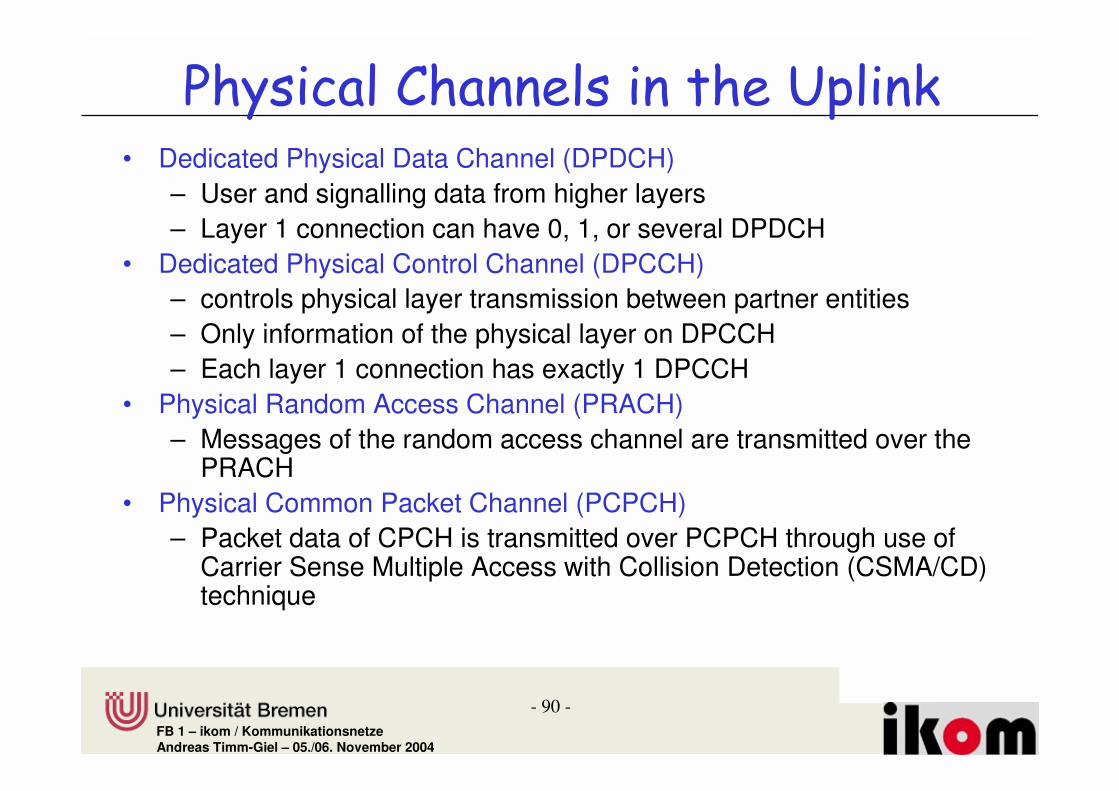
+��%������������%��������� ����,• Dedicated Physical Data Channel (DPDCH)
– User and signalling data from higher layers– Layer 1 connection can have 0, 1, or several DPDCH
• Dedicated Physical Control Channel (DPCCH)– controls physical layer transmission between partner entities– Only information of the physical layer on DPCCH– Each layer 1 connection has exactly 1 DPCCH
• Physical Random Access Channel (PRACH)– Messages of the random access channel are transmitted over the
PRACH• Physical Common Packet Channel (PCPCH)
– Packet data of CPCH is transmitted over PCPCH through use of Carrier Sense Multiple Access with Collision Detection (CSMA/CD)technique

- 91 -FB 1 – ikom / KommunikationsnetzeAndreas Timm-Giel – 05./06. November 2004
+��%������������%��������& �� ����,• Dedicated Physical Channel (DPCH)
– DPDCH and DPCCH are implemented in the downlink in one physical channel, the DPCH
• Common Pilot Channel (CPICH)– Supports macro diversity
• Common Control Physical Channel (CCPCH)– Distribution services over a CCPCH– CCPCH separates into Primary-CCPCH mapped to BCH and
Secondary-CCPCH being mapped to FACH and PCH • Synchronisation Channel (SCH)
– Used for cell search, synchronisation of mobiles• Physical Downlink Shared Channel (PDSCH)
– Used to transmit data over the DSCH (Downlink Shared Channel)– Shared by several mobiles– A DPCH is always allocated to the PDSCH

- 92 -FB 1 – ikom / KommunikationsnetzeAndreas Timm-Giel – 05./06. November 2004
���� �����
��� ��5���� ����� !�� ������������ �
?-)+.� ?���� - ����)������I� ����� � ��� ��������� �� ���
�%)+. ���������������%�����)����4�%)+.� ������#��������#���������� ������
���������
@)+.� @����)������I� �������� �������� ������#������
:)+.� :���� �� )������I� #���� �� �������� ��������
�)+.� ���� ���)������I4�I� ���� ������ ���������

- 93 -FB 1 – ikom / KommunikationsnetzeAndreas Timm-Giel – 05./06. November 2004
+��%������������%.�"& &�������#��� ������&����#��� ��
�#-
:)+
� #-
)@)+
�%)+
&-)+@)+
� ��� ���������#��� �!���#-"� ��� �������#������#��� �!��##-"
@������)�����)����@���� ��)�����@�))@)+�
����������� �� ���#��� �!�� #-"
@���� ��)�����@� ���)�����@)@)+�)�����@����)�����)@�)+�
@���� ���������%�����)�����@�%)+�
%� �����)�����)����@���� ��)�����%�))@)+�%� ���������)�����%)+�
- "��������� ���)�����-�)+�- ����@����#��- "��������� ���)�����-@�-�)+�@������� ���)�����@�)+�)@)+�%������� ���)�����)%�)+�)����������� ��4)�����-������ ��� ���)�����)54)-��)+�
���
��
��

FB 1 – ikom / Kommunikationsnetze
& ���������+��%������������%"& & �# � ����,

- 95 -FB 1 – ikom / KommunikationsnetzeAndreas Timm-Giel – 05./06. November 2004
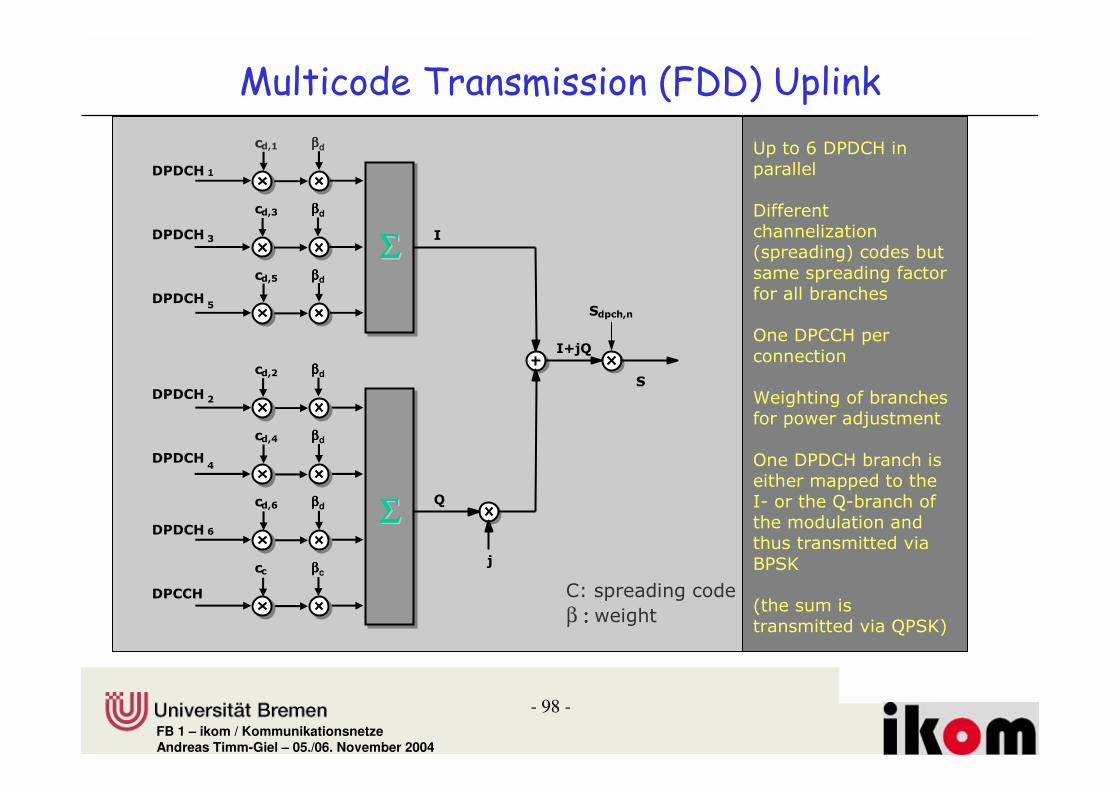
& ���������+��%�����& �����������• Burst has 2560 chips, equivalent to 10/15 ms• 15 bursts in one time frame (10ms)• Time frame in UL always filled, 15 bursts are transmitted continuously
without guard time• DPDCH
– carries coded and interleaved user data of higher layers, transmitting at between 10 bit/burst and 640 bit/burst (depending on spreading factor)
– 640 bit/burst -> 9600 bit/timeframe ->960kbit/s– How can data rates of more than 960 kbit/s be reached?
• One or several (max. 6) DPDCH can be used simultaneously for transmission -> theoretically up to 5760 kbit/s (1920kbit/s required by standard).
• If several are used: then all DPDCH must have the same spreadingfactor between 4 and 256,
• as evenly as possible distributed over I and Q branches.– Variable Rate can therefore be implemented by different spreading
factors, but also by multicodes

- 96 -FB 1 – ikom / KommunikationsnetzeAndreas Timm-Giel – 05./06. November 2004
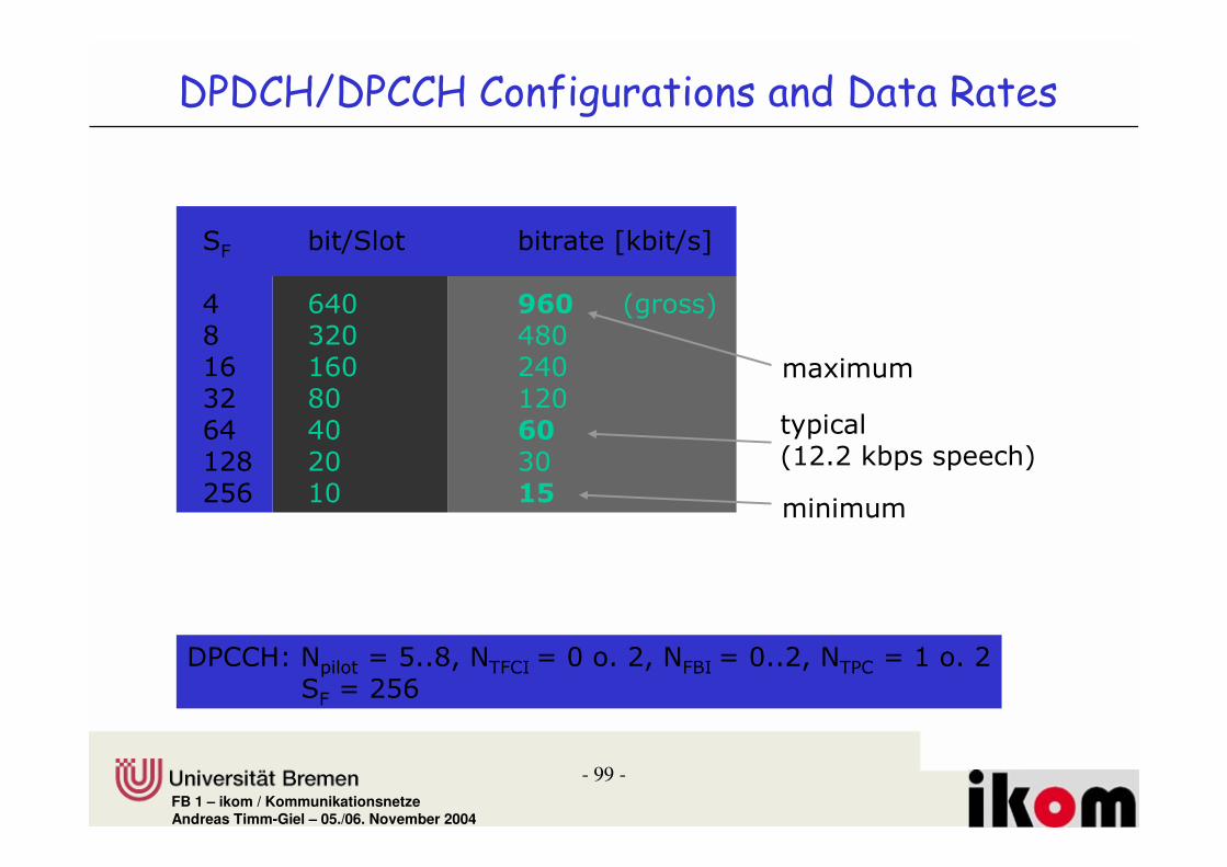
& ���������+��%����������������������& +��4
• Signalling information between physical layers in base station and mobile station;
• exactly one DPCCH per connection• Spreading factor always 256 : What is the data rate??
– one DPCCH burst carries 10 bit, 150 bit/frame -> 15 kbit/s– With at least 1 bit for power control -> 1.5 kbit/s for PC
• 10 bit: 6 different combinations, differing in the length of fields. The fields are:– Pilot Bits– Transport Format Combination Identifier (TFCI) of DPDCH– Feed Back Information (FBI): Power Control Command: +,-,0– Transport Power Control (TPC)

- 97 -FB 1 – ikom / KommunikationsnetzeAndreas Timm-Giel – 05./06. November 2004
����A> ����A2 ����A� ����A2C
2�����������.�'$ /�2B���
& �������� +��%�����������% �"& & 2�� ����,
@��� '@)
'��� /�1*LB� ��� �2B�#�
�@))+&:�'&)�
'&)�.�'�������&�����)��#������������ &:�.�&���#� ����������'@).��'�������@�����)����
5'&)� #�5@�ID' #� 5&:� #� 5'@) #�
�@�)+���
5�-'-#�
'���/�1*LB� ��� �5��� /�2B01� #� ��/B!!L� �2B�!!�LCB�#�4���
%&/1*L41�
- 98 -FB 1 – ikom / KommunikationsnetzeAndreas Timm-Giel – 05./06. November 2004
�1? ββββd
���#-?
�1, ββββd
���#-,
�14 ββββd
���#-4
�1C ββββd
���#-C
�1D ββββd
���#-D
� -��������� ���%� �%%�����"& & �� ����,
�����L��@�)+���
��������
�������� �����,�������������� ���� #�
�������������� ���������#�� ���
D���@))+�����
�� ��
=���������#�� �������������H����
D���@�)+�#�� �������������������� ����O�#�� �������������������� �����������
:@%G
������ �������������O@%G��
�12 ββββd
���#-2
�ΣΣΣΣΣΣΣΣ
H
�&��1�
�:H6
6ΣΣΣΣΣΣΣΣ
�
).��������� ���
β : : : : �����
�� ββββc
��##-
- 99 -FB 1 – ikom / KommunikationsnetzeAndreas Timm-Giel – 05./06. November 2004
%& #�4%�� #����6�#�4�7
C LCB ID> �������F 91B CFB2L 2LB 1CB91 FB 21BLC CB D>21F 1B 9B1*L 2B 2,
& +& �4 *& +��4 ������!-������% ����& ��� ����%
������
��� ���21!1��#�� ���� ��
�������
�@))+.�5���� /�*!!F �5'&)��/�B��!�1 �5&:��/�B!!1 �5'@) /�2��!�1%& /�1*L

FB 1 – ikom / Kommunikationsnetze
& ���������+��%������������%"& & �# & �� ����,

- 101 -FB 1 – ikom / KommunikationsnetzeAndreas Timm-Giel – 05./06. November 2004
& ���������+��%������������• Physical channels are not separated I and Q branches in downlink. • Therefore only one Dedicated Physical Channel (DPCH) taking over
the tasks of DPDCH and DPCCH of the uplink (kind of time multiplexing).
• Data Rate– 2560 chips/burst, burst 10/15ms– spreading factor between 4 and 512– QPSK – symbol rate to bit rate ??
• DPCH burst:– 17 possible burst variations– 2 data fields for higher layer data, corresponds to DPDCH– TPC, TFCI and pilot are equivalent to DPCCH fields in uplink
• If bit rate of DPCH is not sufficient for CCTrCH, then CCTrCH can be mapped to several DPCH with same spreading factor and transmitting in parallel
• With several DPCH for one UE, DPCCH information only required once, fields in further DPCHs remain empty (DTX)
• Parallel operation is also required for multiple user

- 102 -FB 1 – ikom / KommunikationsnetzeAndreas Timm-Giel – 05./06. November 2004
������������ �'� /�2B���
%�� SB %�� S2 %�� S� %�� S2C
& �������� +��%�����������% �"& & �& �� ����,
'���/�1*LB� ��� �2B01� #� ��/B!!M�
'@)5'@) #�
���15���1#�
�@�)+
'&)�5'&)� #�
@���5����#�
���25���2#�
�@�)+ �@))+ �@))+
�@)+.�������������������@�)+�����@))+
%&/*2141�

- 103 -FB 1 – ikom / KommunikationsnetzeAndreas Timm-Giel – 05./06. November 2004
�
���
# � %& �
H
%��
O
�3HO@���� �� ����
������������ ���#���
%
ΣΣ!!!
!!!
J2
J4
����������
���� "4� ���� (� " � �� ������� " ��� � ��� �2 � ,�

- 104 -FB 1 – ikom / KommunikationsnetzeAndreas Timm-Giel – 05./06. November 2004
��� �
�������#��� �4
��� ��������#��� ��
��� �����!4,D>�#��&�"
KKK
��� �
�������#��� �2
���#-
�/#� &������#
���#-
� -��������� ���%� �%%�����"& & �& �� ����,
Increased power for control information, a) because physical layer info is very important, b) to have an even transmit power

- 105 -FB 1 – ikom / KommunikationsnetzeAndreas Timm-Giel – 05./06. November 2004
%& #�4%�� #���� ���!�#����6�#�4�7 �@�)+�6�#�4�7
C 21FB 2;1B 2FM12FM1F LCB ;LB ;212L 91B CFB C9191 2LB 1CB 12BLC FB 21B ;B21F CB LB *2*21*L 1B 9B 1C*21 2B 2* LL
& +�4 ������!-������% ����5 ��%% & ��� ����%
������ ��� ���
������������ ��� ���������@)+
��� ���21!1��#�4������ ��

- 106 -FB 1 – ikom / KommunikationsnetzeAndreas Timm-Giel – 05./06. November 2004
� �6�� -� �& ���������# & �� ����,
• Multicode implies all DPCH use the same spreading factor
• Base Station needs further channels, e.g. CPICH• Maximum data rate is determined by spreading
factor 4 and 3 parallel channels • Gross data rate includes coding. Deduce coding
with coding rate 1/3 approx. 2 Mbit/s is max. available for one user.
• This is also the cell capacity

- 107 -FB 1 – ikom / KommunikationsnetzeAndreas Timm-Giel – 05./06. November 2004
��� ���%%���� ���
• Objectives:– If UE wants to switch to other frequency
channels or to GSM, it has to receive and decode pilot signals on other frequency bands
– Receiving in different frequency bands simultaneously is difficult
– > Compressed Mode

- 108 -FB 1 – ikom / KommunikationsnetzeAndreas Timm-Giel – 05./06. November 2004
2B������������
'������������������������������������� �������������"�� � �����
��� ���%%�� � ���
���������������� �������������������� ��
�� ������������������ ��������
���
�����

FB 1 – ikom / Kommunikationsnetze
������ �' ���%%�+�����-��"& &

- 110 -FB 1 – ikom / KommunikationsnetzeAndreas Timm-Giel – 05./06. November 2004
������ �' ���%%�"& &• Physical Random Access Channel (PRACH) is used for
random access in the uplink.• Random access can be performed at defined times
(access slots)• Access Slot:
– 5120 chips (2xnormal slot), – 15 access slots exist within 20 ms.– Availability of Access slots is broadcasted on BCH
• -> flexible, possible to allocate different acccess slots to different service classes
• Random Access = Contention Phase + Transmission Phase
- 111 -FB 1 – ikom / KommunikationsnetzeAndreas Timm-Giel – 05./06. November 2004
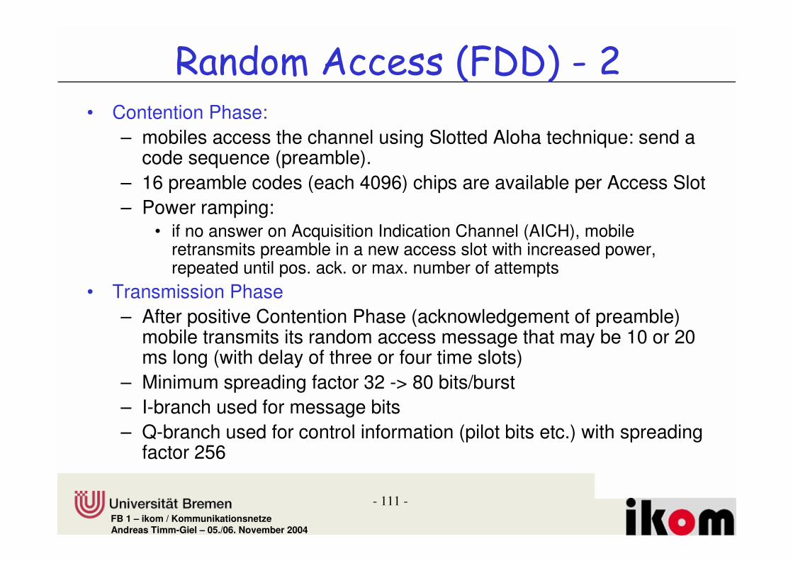
������ �' ���%%��"& & �# )• Contention Phase:
– mobiles access the channel using Slotted Aloha technique: send acode sequence (preamble).
– 16 preamble codes (each 4096) chips are available per Access Slot– Power ramping:
• if no answer on Acquisition Indication Channel (AICH), mobile retransmits preamble in a new access slot with increased power, repeated until pos. ack. or max. number of attempts
• Transmission Phase– After positive Contention Phase (acknowledgement of preamble)
mobile transmits its random access message that may be 10 or 20 ms long (with delay of three or four time slots)
– Minimum spreading factor 32 -> 80 bits/burst– I-branch used for message bits– Q-branch used for control information (pilot bits etc.) with spreading
factor 256

- 112 -FB 1 – ikom / KommunikationsnetzeAndreas Timm-Giel – 05./06. November 2004
A> A2 A4 A? AC A, AD AE AB AI A2> A22 A24 A2? A2C
,24>����&
���$�� (�2>��� ���$�� (�2>���
� ��� ����
���� �� ��������������
���� �� ��������������
���� �� ��������������
������ ' ���%%�+�����-�� �"& &
CB;L� ���
�� ���
���������
� ��+ &��
2B���������1B���
��������������
�� ��� �� ���

- 113 -FB 1 – ikom / KommunikationsnetzeAndreas Timm-Giel – 05./06. November 2004
@���5����#�
'��� /�1*LB� ��� �2B�#�
'&)�5'&)� #�
���5���#�
'��� /�1*LB� ��� �5��� /�2B01� #� ��/B!!9� � 2B�!!�FB�#�4���
����A> ����A2 ����A� ����A2C
2�����������.�'$ /�2B���
?���� - ����'��������� !!!
�
O
������ ' ���%%�7-�%� ����� ����

- 114 -FB 1 – ikom / KommunikationsnetzeAndreas Timm-Giel – 05./06. November 2004
������ ������+�����-��• UE needs to identify the downlink scrambling code
1. Synchronise to the time slots of the cell. Therefore UE listens to Primary Synchronisation Channel (P-SCH) using the primary synchronisation code (PSC).
• PSC is same in all cells and 256 chips long• Matched filter can be used, produces a series of impulses due to
autocorrelation properties2. Secondaray Synchronisation Channel (S-SCH) is used to identify the
code group• Evaluation of three successive 256 chip blocks is sufficient to detect
the position within the frame and to identify group code used3. Terminal then compares all possible code sequences of a group with
the primary code used by the Common Pilot Channel (CPICH)• Only 8 primary codes are defined per code group, therefore fast
identification possible� Primary Common Control Physical Channel (P-CCPCH), which is
transmitting system and cell-specific information can now be read

FB 1 – ikom / Kommunikationsnetze
+���%����������%�� & &

- 116 -FB 1 – ikom / KommunikationsnetzeAndreas Timm-Giel – 05./06. November 2004
+��%������������%����� & &• Same transport channels exist for TDD and FDD (with few exceptions)• Physical layer protocol stack shows differences:
– In TDD physical channel is defined by spreading code, frequency channel and time slot within time frame. Physical channel can occupy a time slot in each time frame or only in a subset of allframes.
• Most important Physical Channels:– Dedicated Physical Channel (DPCH)
• UL/DL, for user and control data
– Common Control Physical Channel (CCPCH)• Broadcast services in cell on downlink• Divided into primary (BCH, Cell info) and secondary (FACH, PCH i.e.
Power Control & Paging)

- 117 -FB 1 – ikom / KommunikationsnetzeAndreas Timm-Giel – 05./06. November 2004
+��%������������%����� & & �# )– Physical Random Access Channel (PRACH)
• UL only• Carries out random access
– Physical Uplink Shared Channel (PUSCH)• user and control data
– Physical Downlink Shared Channel (PDSCH)– Paging Indication Channel (PICH)
• Carries out paging, • can replace ono or more subchannels for paging on S-CCPH
– Physical Node B Synchronisation Channel (PNBSCH)• NodeB synchronisation over the air

- 118 -FB 1 – ikom / KommunikationsnetzeAndreas Timm-Giel – 05./06. November 2004
+��%������������%.�� & &
���� ���@���� ��)������@)+�
@������)�����)����@���� ��)�����@�))@)+�
%� �����)�����)����@���� ��)�����%�))@)+�
@���� ��?���� - ����)�����@?-)+�
@���� ��������%�����)�����@�%)+�
@���� ���������%�����)�����@�%)+�
@������� ���)�����@�)+�
%� ���������)�����%)+�
�)+
:)+
&-)+
@)+
?-)+
D?-)+
�%)+
�%)+
����&����#��� �� �������#��� ��
@���� ��5����:�%� ���������)�����@5:%)+�
'�������� ����������
'������ ����������
�����4�������%� ���������)�������@)+ ���@)+�
&���@���� ��- ����)�����&@-)+�

- 119 -FB 1 – ikom / KommunikationsnetzeAndreas Timm-Giel – 05./06. November 2004
7-�%��� ���%����� & &• Length of Burst = length of a time slot • Each burst has four fields:
– 2 data fields, – „midample sequence“ – training sequence used for channel assessment
and support of joint detection at the receiver– „guard period“ – accounting for different runtime of different UEs
• Burst Type 1:– long midample, short guard period– Used in UL and DL– Max. 16 burst type 1 may be used simultaneously in one time slot and
transmission direction (depending on spreading code)• Burst Type 2
– Shorter midample, longer data fields– Used in DL because perfect synchronisation, therefore shorter midample
possible– Used in UL, if less than four bursts per slot are transmitted simultaneously
• Burst Type 3– Longer guard period for random access and handover

- 120 -FB 1 – ikom / KommunikationsnetzeAndreas Timm-Giel – 05./06. November 2004
���������IED����&
����� ,24����&
���������IED����&
J�ID#�
4,D>L��
#��� ���2
������ � ���#���
���������22>C����&
����� 4,D����&
J�ID#�
4,D>L��
���������22>C����&#��� ���1
& �������� +��%������������& +�4
���������IED����&
����� ,24����&
J�
2I4����&
4,D>L��
���������BB>����&#��� ���9

- 121 -FB 1 – ikom / KommunikationsnetzeAndreas Timm-Giel – 05./06. November 2004
� ������!����7-�%��� ���%�����+��%������������%
XPRACH
XXS-CCPCH
XP-CCPCH
X (only UL)XXDPCH, PUSCH, PDCH
Type 3Type 2Type 1Physical Channel
PICH, SCH use diferent time and burst structures

- 122 -FB 1 – ikom / KommunikationsnetzeAndreas Timm-Giel – 05./06. November 2004
& +�4 ������!-������% ����5 ��%% & ��� ����%
������ ��� ����������� �������
#�4��� ��� �����2����� ��� �����2����4�������
6�#�4�7 6�#�4�7
%& ���2 ���1 ���2 ���1 ���2 ���1
2 9;BC CC2L *F*L LL1C 9;B C CC2 LCC2 L1 2;*1 11BF 1;1F 9921 2;* 1 11B FC ;ML 22BC 2CLC 2L*L ;M L 22B CF CFF **1 M91 F1F CF FCF F ** 12L 1CC 1ML 9LL C2C 1C C1C C 1M L
'��� ���21!1��#�4������ ��
������� ��� ����������� �������
Standard describes:
•Mobiles with max. 9 time slots inUL and 12 time slots in DL
-> max 3974.4 kbit/s UL and5299.2 kbit/s in DL gross data rate

- 123 -FB 1 – ikom / KommunikationsnetzeAndreas Timm-Giel – 05./06. November 2004
� -��������*�� -���%��� � ���%� �%%���
���
�����#��
'&)�
'@)���I�
4,D>L��
'&)�����'@)������� #��� ���
���� ������� ���
�������
)���
4,D>L��
'&)�����'@)�����#��� ���
��#������������#��/#������ %� �&� ��+�� 2D
'&)�.�'�������&�����)��#������������'@).��'�������@�����)����

- 124 -FB 1 – ikom / KommunikationsnetzeAndreas Timm-Giel – 05./06. November 2004
� -������6��!����+��%������������%��� & &
@���� ���)������������
ΣΣΣΣΣΣΣΣγγγγ2
γγγγ4
J�#-
�#-
ΣΣΣΣΣΣΣΣ
@���� ���)�������������
ΣΣ!!!
!!!
J2
J4
J
ββββ
• Different Physical Channels are multiplexed into one time slot before modulation
• Every 2 consecutive bits are combined into a complex valued symbol, that is spread with actual spreading code of the physical channel and then scrambled wit a cell-specific scrambling code.
• Each branch is subject to weighting γ matching power to physical channel power requirements (spreading factor, margins).
• Weighting with β according to actual transport format combination.• In uplink same procedure is followed for second CCTrCH• Downlink similar, but each physical channel is weighted on its own.

- 125 -FB 1 – ikom / KommunikationsnetzeAndreas Timm-Giel – 05./06. November 2004
�������������!2�� -������6��!2�����������!�����+��%�������������� �����!
@���� ��)�����
�������- ����)���� ��-)�
'�������)�����
@���� �������
)���� ���������
� !
����������
%�������
)���� ����������
� !
)���� ���������
� !
)���� ���������
� !
)���� ���������
� !
)����)�������'�������)�����))'�)+))'�)+

- 126 -FB 1 – ikom / KommunikationsnetzeAndreas Timm-Giel – 05./06. November 2004
� �����!����� ���%������������%����+��%����
• Transport Blocks are transmitted over transport channels; transport blocks pass a chain of security and matching functions, e.g. channel coding, interleaving and puncturing
• Data blocks that are subject of same coding interleaving and matching can be multiplexed to CCTrCH
• CCTrCH is mapped through segmentation to one or several physical channels
• Physical channel therefore can transmit the signalling and user data of different transport channels simultaneously

- 127 -FB 1 – ikom / KommunikationsnetzeAndreas Timm-Giel – 05./06. November 2004
(�����$6�� ���• 12.2 kbit/s voice transmission• In MAC two logical channels Dedicated Traffic
Channel (DTCH) and Dedicated Control Channel (DCCH) are mapped into two Dedicated Channels (DCH). Mapping defines transport blocks with 244bit user data every 20 ms over transport channel 1 and 100 bits every 40 ms over second transport channel
• Channel coding and rate matching for both are same -> can be multiplexed into one CCTrCH
• No multicode or multislot is required, one dedicated physical channel
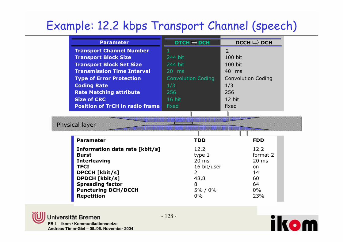
- 128 -FB 1 – ikom / KommunikationsnetzeAndreas Timm-Giel – 05./06. November 2004
��� � � ��#-������#- �##-�������#-
����&����#��� ��%�� � 2� 1
����&����=�������. 1CC�#� 2BB�#�
����&����=������ ����. 1CC�#� 2BB #�
��������������� ���� �0� 1B� �� CB ��
��& ��$�;��������� ����� )�������)���� )�������)����
#���+�� 249 249
�� �������+�����%� 1*L 1*L
��. �$�#�# 2L�#� 21�#�
����������$���#-������$�� ����� �����
��� � � ��� /��
��$����������� �F������G 21!1� 21!1=%��� ���2 ����� 1��� �� 0��+ 1B��� 1B����/#� 2L�#�4���� ���##-�F������G 1� 2C����#-�F������G CF F LB�&� ��+$���� F LC�%���%���+�#-��##- *R�4�BR BR� & ������ BR 19R
$6�� ���.��)�)�,8�% � ���%�������������%�����
@���� �������

- 129 -FB 1 – ikom / KommunikationsnetzeAndreas Timm-Giel – 05./06. November 2004
�)+�)+
#��0��#���+�32�? FBC
2������ �� 0��+ FBC
CB1����/�� �� +� ������
CB1
�� �������+ C;B C;B C;B C;B
#�#������ ��2D�#�#����
1CC
����������� �� 1LBB�������
�)+�)+��$��������� 2>>
22B 22B 22B 22B
9LB
9LB
221B�������
2BB24�#�#����
#�#������ ��
����������� ��
#��0��#���+�32�?
�� �������+
2������ �� 0��+
;B ;B ;B ;B
D>���&� ���#-
?����������
D>> D>> D>>
2,���&� ��##-
D>>
@���� �������
4������ �� 0��+
C;B 22B C;B 22B C;B 22B C;B 22B
2,LC> 2,LC> 2,LC> 2,LC>
� �%�� �� ���� �%�� �� ���#������#������!� #"!� #"
&��&��
��$��������� 1CC 1CC

- 130 -FB 1 – ikom / KommunikationsnetzeAndreas Timm-Giel – 05./06. November 2004
2������ �� 0��+ B>C #�41B��
6�1LB�3F�7��9/� B>C#��0��#���+2�?
�%���%���+
�� �����+?B> ?B>
4����� �� 0��+ CE> CE> CE>CE>
CE> CE> CE> CE>�/#������#
�/*� +� ������ C>4 C>4
1CC#�#������ �� 2L
����������� �� F4D> #�41B��
2BB 21
F221
21B���9/� ?D>
I> I> I> I>
?D>
I> I> I> I>
2>>�)+�)+
�/3B
?�����&�����S2 ?�����&�����S1 ?�����&�����S9 ?�����&�����SC
19L 19C��� 19L 19C��� 19L 19C��� 19L 19C���
����� +� ������ @���� �������
� �%�� �� ���� �%�� �� ���#������#������
� �0�� ��%���&� '� ?B> ?B> ?B> ?B>I> I> I> I>
1CC 2L
?B> ?B>
6�1LB�3F�7��9/� B>C
B>C #�41B��
C>4 C>4
F4D> #�41B��
4CC��$��������� 4CC �)+�)+ '��'��
'&)�
'@)

- 131 -FB 1 – ikom / KommunikationsnetzeAndreas Timm-Giel – 05./06. November 2004
���������?,4����&
����� 2CC����&
���������?,4����&
J�2D#�
BDCL��
�@)+�#���
� & & �� ������� ���� ����������� 8-�%�%
+%�& ���?4����&
IDL��
�@�#M��DC����&��@)+#���
+%�& ���
?4����&
2D>L��
�@�#M��
24B����&��@)+#���

- 132 -FB 1 – ikom / KommunikationsnetzeAndreas Timm-Giel – 05./06. November 2004
� & & ���� ���� �����!��%% ���� ����%
��� ��� ��� ���
:�����4%�� 2����4��#������ L�����4��#������6�#�4�7 6�#�4�7
%& O@%G F@%G O@%G F@%G O@%G F@%G
2 2CBF 1221 1B;!L C11!C 21*M!L 1*9C!C1*9C!C1 MB2 � 2CB!1 � FC2!1 �C 9*1 � MB!C � C11!C �F 2ML � 9*!1 � 122!1 �2L FF 291 2M!L2M!L 1C!L 2B*!L 2*F!C
5��.����I����%& 2���2L

FB 1 – ikom / Kommunikationsnetze
����������3
Cellular CDMA Networks

- 134 -FB 1 – ikom / KommunikationsnetzeAndreas Timm-Giel – 05./06. November 2004
������������ ����& � '• Interference is very special in comparison to TDMA/FDMA
networks– In CDMA all user utilise same frequency channel
• Relatively high co-channel interference (also from same cell)• Carrier-to-interference ratio are appropriately low
– Co-Channel interference in TDMA/FDMA networksalways originates from other cells. In CDMA networksall users of the same cell also cause interference(CDMA typically cluster size 1)

- 135 -FB 1 – ikom / KommunikationsnetzeAndreas Timm-Giel – 05./06. November 2004
������������ ����& � '
)4��/�)
����
��� ���.�������������� ���������� �������������������"�� � �������������- ����������� ��
���� 88�������� ����<�B��:
��� ���.�������������� ������ �������������������"�� � ����
3�����
UPLINK

- 136 -FB 1 – ikom / KommunikationsnetzeAndreas Timm-Giel – 05./06. November 2004
����7�������!• Specified service specific C/I needs to be maintained at receiver to
guarantee QoS• Growth of traffic leads to an increase of interference power (intracell as
well as intercell)• If transmitter power cannot be further increased, maximum cell size
decreases as specific C/I also at far receiver is required.• Load depend maximum cell size is referred to as „cell breathing“.• As network load changes over the day, also the maximum cell size
changes over the day.• Breathing is determined by intracell interference, which itself depends
on orthogonality of codes and quality of receiver.– Because FDD uplink only quasiorthogonal codes are used (in TDD
UL/DL and FDD DL orthogonal codes are used): UMTS FDD UL ismost affected by cell breathing.

- 137 -FB 1 – ikom / KommunikationsnetzeAndreas Timm-Giel – 05./06. November 2004
����#7�������!
��������� �
������ ����
���� ������� �
������� ���� �#� �����������
���� �������� �
���� �������
� ����������� � ����������� � ����������� � �����������

- 138 -FB 1 – ikom / KommunikationsnetzeAndreas Timm-Giel – 05./06. November 2004
/��,�7-�!���$6�� ��� "& & �� /2�%�����2�9�,8��*%
�;�;����F=�G
� � �0 ������ /���� F=�G��� �$ � �� ��� ��F=�G�����!���� :���� �$ � �� "�F=�G
� )%�� #���F=G� � �0 ��� �����0���F=�G
J��� ������ � ���� =��F=G�'��%��������� F=G
/��+���+��F=G-��0 � J��F=G�����=%+ ��F=G
42
*2>?*IB�4D*IE
*4>�I*22E�I
222CI�I
22�??2C>�E
/���/���
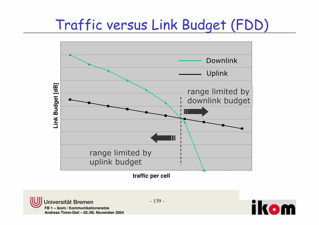
- 139 -FB 1 – ikom / KommunikationsnetzeAndreas Timm-Giel – 05./06. November 2004
traffic per cell
Link
Bud
get [
dB]
������
�����
����������#�������#����
����������#��������#����
� ������ ��%-% /��,�7-�!����"& &

- 140 -FB 1 – ikom / KommunikationsnetzeAndreas Timm-Giel – 05./06. November 2004
������: ��� ��, +������!
������� ����#�������� �����,��������������� ������������������
���������������
��� ��
�������
"������������� �

- 141 -FB 1 – ikom / KommunikationsnetzeAndreas Timm-Giel – 05./06. November 2004
� ������ ��������• Issues to mention:
– Required C/I depends on data rate and QoS requirements
– Therefore cells can breathe differently fordifferent services / data rates / QoS requirements
– Radio coverage with services with a high spreading factor is therefore higher than forservices with a low spreading factor
– Depending on dimensioning high data rate services could only be available close to NodeB

- 142 -FB 1 – ikom / KommunikationsnetzeAndreas Timm-Giel – 05./06. November 2004
������������
&����I.� "������������� ���� �������������� �� ������ ����� ����
)/�
20)
��2� 0�)
/9�����
�

- 143 -FB 1 – ikom / KommunikationsnetzeAndreas Timm-Giel – 05./06. November 2004
��� �����#�� ��� �������� ������"����������� )4�������
maximum achievable C/I as a function of the number of users per cell
-25
-20
-15
-10
-5
0
2 5 10 20 30 40 50 60 70 80 90 100
110
120
130
number n of active users per cell
C/I
[dB
]

- 144 -FB 1 – ikom / KommunikationsnetzeAndreas Timm-Giel – 05./06. November 2004
��2� 0�)�3��������3�����
)
�/
20)
� -���#������������
intracell

- 145 -FB 1 – ikom / KommunikationsnetzeAndreas Timm-Giel – 05./06. November 2004
� ���#4 ������
)@�)+�2
)@�)+�1
)@�)+�9
�� ��� ���2
�� ���� ���2���� ���1
�� ���� ���1���� ���9
+D������
∆'
��� ���5�!�1
∆'
��� ���5�!�9 ������� ���5�!�2
���
�������������

- 146 -FB 1 – ikom / KommunikationsnetzeAndreas Timm-Giel – 05./06. November 2004
� %�% ����+-���%� ���� ����4 ������
������������� ������������ �
������������� ������������� �
�������"�����)4������������������ ����
���������� ����������#��������� �������
���� ������� �
������ ��� ��

FB 1 – ikom / Kommunikationsnetze
$���������� �
UMTS Radio Interface