ump - monitoring - epfl · ump - monitoring unbalanced magnetic ... epf-lausanne laboratoire de...
TRANSCRIPT

UMP - MONITORING
UNBALANCED MAGNETIC PULL AND AIR-GAP MONITORING FOR LARGE HYDROGENERATORS
AN INNOVATIVE MEASUREMENT DEVICE FOR THE MONITORING OF STATOR AND ROTOR MAGNETIC CIRCUITS
Dr. Mai Tuxuan, Prof. Jean-Jacques Simond, Dr. André Hodder, Roland Wetter, Minh Tuan Nguyen
Laboratory of Electrical Machines - Institute of Energy Sciences
Lausanne, December 2004

EPF-LAUSANNE Laboratoire de machines électriques (LME) 2
UNBALANCED MAGNETIC PULL AND AIR-GAP MONITORING FOR LARGE HYDROGENERATORS
AN INNOVATIVE MEASUREMENT DEVICE FOR THE MONITORING OF STATOR AND ROTOR MAGNETIC CIRCUITS
1. OBJECTIVES
Large low speed hydrogenerators have a very small specific air-gap/stator bore diameter ratio making it impossible to have a perfect centering of the elements during the assembly process. This results in that the machines are operated with an eccentricity that though small is not negligible, and is the cause of undesirable effects: considerable unbalanced magnetic pull forces, vibrations, additional losses. It is therefore important to assess the eccentricity and even more to check its trend to guarantee a safe operation and prevent any serious damage. The purpose of the instrument UMP Monitoring system (Unbalanced Magnetic Pull Monitoring) is to detect synchronous machines stator and rotor circuit defects. These defects, of mechanical origin (wrong positioning of the rotor, mechanical unbalance, mechanical deformation…) or electromagnetic (partial short-circuit of the field coil, magnetic circuit defect…), may engender important magnetic strains between the stator and the rotor giving rise to vibrations and in the worst cases a sticking of the rotor and the stator. Early detection of air-gap anomalies eases the maintenance task by giving the user time to plan for repairs before scheduled outages. Prediction of long term evolution of gap and shapes can be used in operational and rehabilitation planning. Knowing the magnitude of the magnetic pull between rotor and stator can inform the operator of the need of removing a machine from service before serious damage such as a rotor stator rub occurs.
EPF-LAUSANNE Laboratoire de machines électriques (LME) 3
2. ELEMENTS OF THE EQUIPMENT The equipment comprises :
- devices to measure the magnetic flux in the air-gap of the machine; - data acquisition units (analog–digital conversion of the signals provided by the
measuring elements); - data processing tools to extract the parameters related to stator and rotor magnetic
circuit defects.
2.1. Sensors to measure the magnetic flux in the air-gap
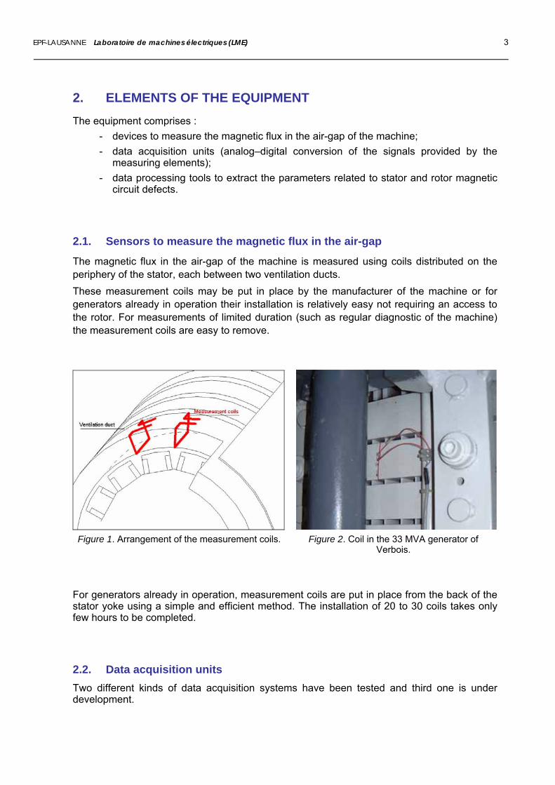
The magnetic flux in the air-gap of the machine is measured using coils distributed on the periphery of the stator, each between two ventilation ducts. These measurement coils may be put in place by the manufacturer of the machine or for generators already in operation their installation is relatively easy not requiring an access to the rotor. For measurements of limited duration (such as regular diagnostic of the machine) the measurement coils are easy to remove.
Figure 1. Arrangement of the measurement coils. Figure 2. Coil in the 33 MVA generator of
Verbois. For generators already in operation, measurement coils are put in place from the back of the stator yoke using a simple and efficient method. The installation of 20 to 30 coils takes only few hours to be completed.
2.2. Data acquisition units Two different kinds of data acquisition systems have been tested and third one is under
evelopment. d
EPF-LAUSANNE Laboratoire de machines électriques (LME) 4
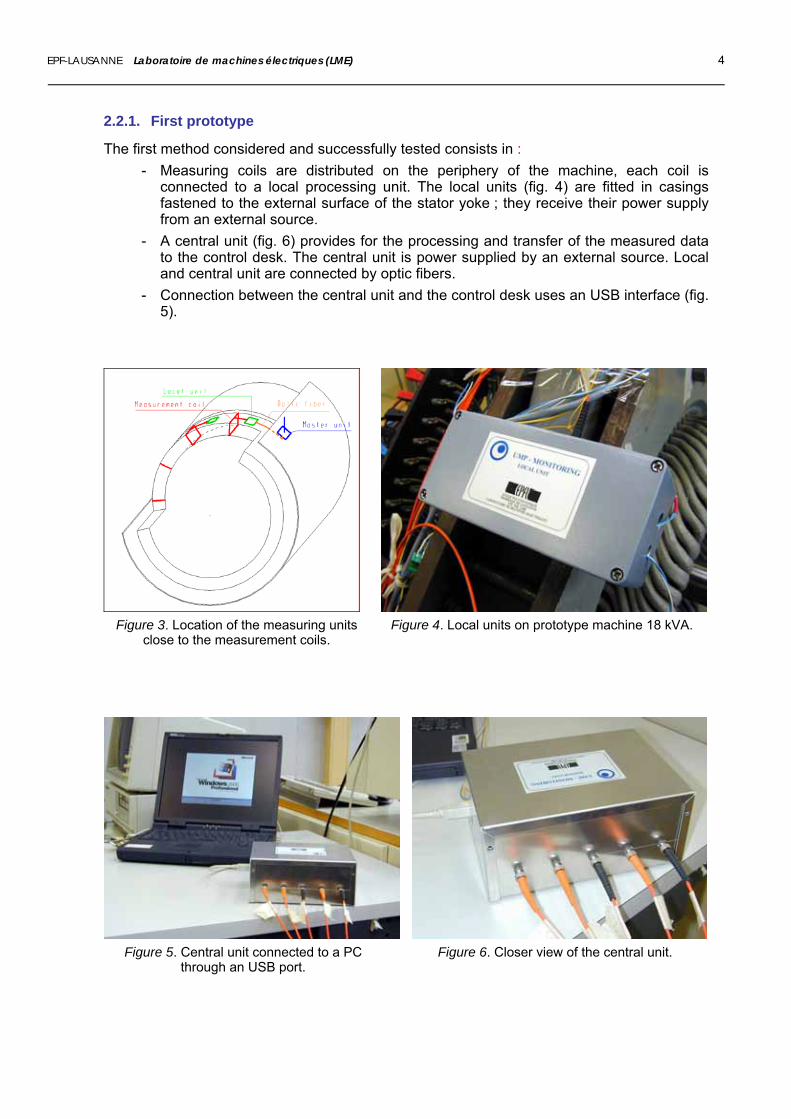
2.2.1. First prototype
The first method considered and successfully tested consists in : - Measuring coils are distributed on the periphery of the machine, each coil is
connected to a local processing unit. The local units (fig. 4) are fitted in casings fastened to the external surface of the stator yoke ; they receive their power supply from an external source.
- A central unit (fig. 6) provides for the processing and transfer of the measured data to the control desk. The central unit is power supplied by an external source. Local and central unit are connected by optic fibers.
- Connection between the central unit and the control desk uses an USB interface (fig. 5).
Figure 3. Location of the measuring units
close to the measurement coils. Figure 4. Local units on prototype machine 18 kVA.
Figure 5. Central unit connected to a PC through an USB port.
Figure 6. Closer view of the central unit.
EPF-LAUSANNE Laboratoire de machines électriques (LME) 5
2.2.2. Second prototype
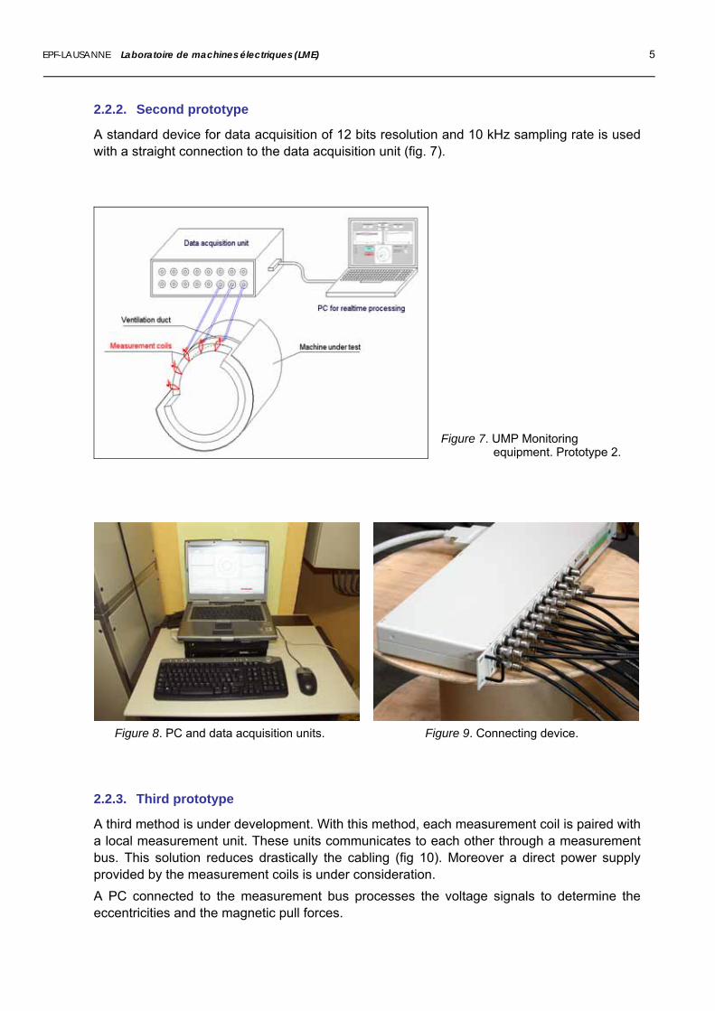
A standard device for data acquisition of 12 bits resolution and 10 kHz sampling rate is used with a straight connection to the data acquisition unit (fig. 7).
Figure 7. UMP Monitoring equipment. Prototype 2.
Figure 8. PC and data acquisition units. Figure 9. Connecting device.
2.2.3. Third prototype
A third method is under development. With this method, each measurement coil is paired with a local measurement unit. These units communicates to each other through a measurement bus. This solution reduces drastically the cabling (fig 10). Moreover a direct power supply provided by the measurement coils is under consideration. A PC connected to the measurement bus processes the voltage signals to determine the eccentricities and the magnetic pull forces.
EPF-LAUSANNE Laboratoire de machines électriques (LME) 6
LMU
... Measurement coils
Local measurement units (LMU)...LMU LMU LMU
Figure 10. Working scheme of prototype 3.
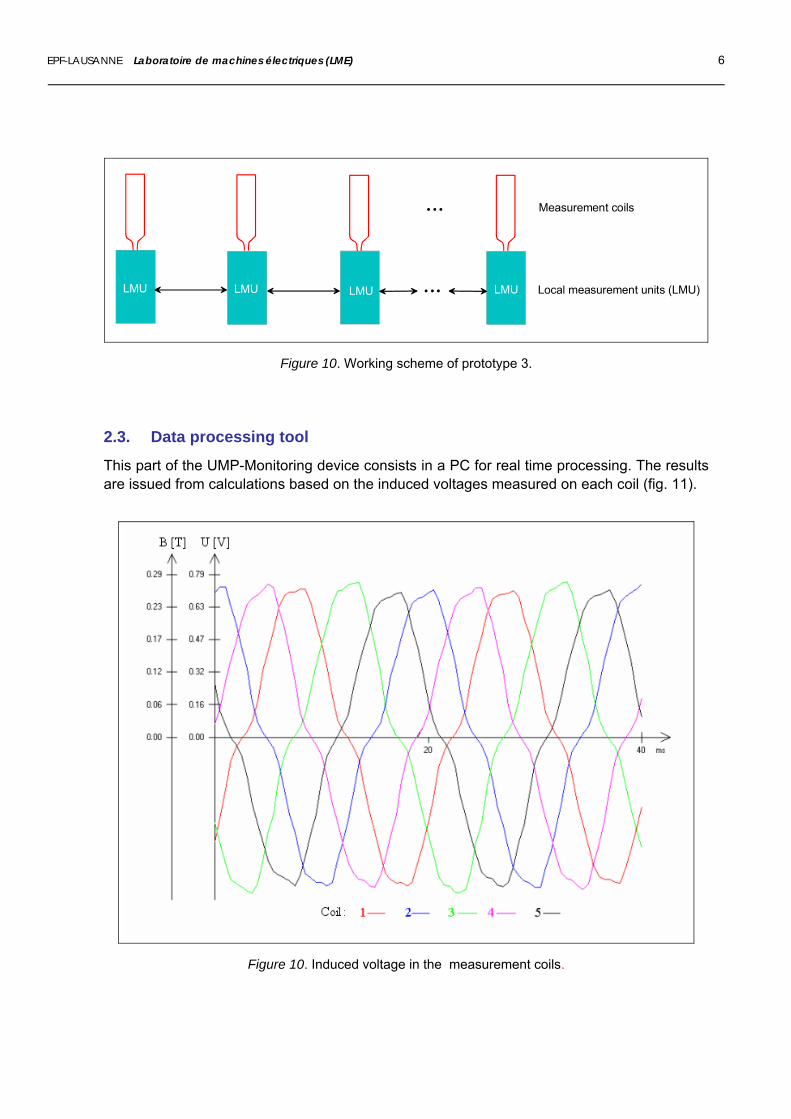
2.3. Data processing tool
This part of the UMP-Monitoring device consists in a PC for real time processing. The results are issued from calculations based on the induced voltages measured on each coil (fig. 11).
Figure 10. Induced voltage in the measurement coils.

EPF-LAUSANNE Laboratoire de machines électriques (LME) 7
3. MEASUREMENT MAIN FEATURES
3.1. Calculated quantities
The measurement is performed in real time over a complete revolution of the rotor. Consequently, the period between two successive measurements depends directly on the rotation speed of the generator. Analysis of the measurements provides a complete information regarding the condition of the magnetic circuits related to the air-gap:
► deformation of the stator magnetic circuit; ► relative effective static and dynamic eccentricities; ► magnitude and direction of static and dynamic magnetic pulls; ► air-gap magnetic flux.
The UMP-monitoring equipment provides a numerical and graphical representation of the rotor magnetic circuit state, stator deformation, and the combination of these two states as well as an harmonic analysis of the deformations.
3.2. Measuring rate
E stimated period between 2 successive measurements :
∆t = 2p / f + 0.8 [s] E xamples :
GUIGANG (China) Hydrogenerator 32.6 MVA 2p = 76 f = 50 [Hz] ∆t = 2.32 [s]
Prototype machine of the LME 18 kVA
2p = 10 f = 50 [Hz] ∆t = 1.0 [s]

EPF-LAUSANNE Laboratoire de machines électriques (LME) 8
4. BENEFITS FROM AN AIR-GAP MONITORING BY VOLTAGE MEASUREMENT
4.1. Measurement sensors Type of sensor
- simple and very low cost Sensor set-up
- easy with minimal intervention on the machine; - no direct access to the air-gap necessary; - no gluing; - no mechanical disassembling / reassembling; - fast with simple tools.
4.2. Measuring equipment - measurement of voltages in an unproblematic range (between 1 and 3 V); - several methods of data acquisition possible.
4.3. Data processing unit - standard PC; - easy to adapt to specific user wishes; - possibility to have remote display through internet.
4.4. Innovative features of the system - low cost sensors; - insensitivity to external conditions (humidity, temperature, etc.) - measurement of static and dynamic induced pull; - capability to recognize deformation of any shape; - arbitrary number and disposition of sensors; - real-time assessment of air-gap condition; - no influence of the cables on the measurement; - no need of linearization.
EPF-LAUSANNE Laboratoire de machines électriques (LME) 9
5. EXAMPLES OF MEASUREMENT
5.1. Laboratory prototype machine
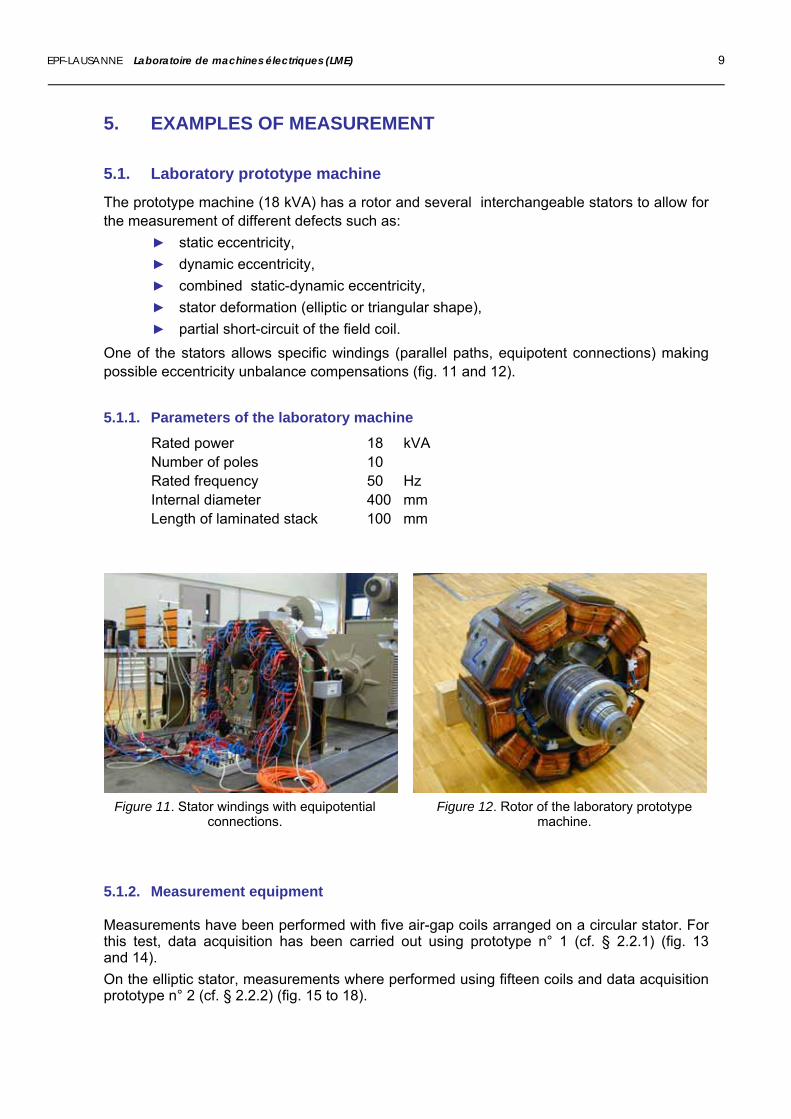
The prototype machine (18 kVA) has a rotor and several interchangeable stators to allow for the measurement of different defects such as:
► static eccentricity, ► dynamic eccentricity, ► combined static-dynamic eccentricity, ► stator deformation (elliptic or triangular shape), ► partial short-circuit of the field coil.
One of the stators allows specific windings (parallel paths, equipotent connections) making ossible eccentricity unbalance compensations (fig. 11 and 12). p
5.1.1. Parameters of the laboratory machine
Rated power 18 kVA Number of poles 10 Rated frequency 50 Hz Internal diameter 400 mm Length of laminated stack 100 mm
Figure 11. Stator windings with equipotential
connections. Figure 12. Rotor of the laboratory prototype
machine.
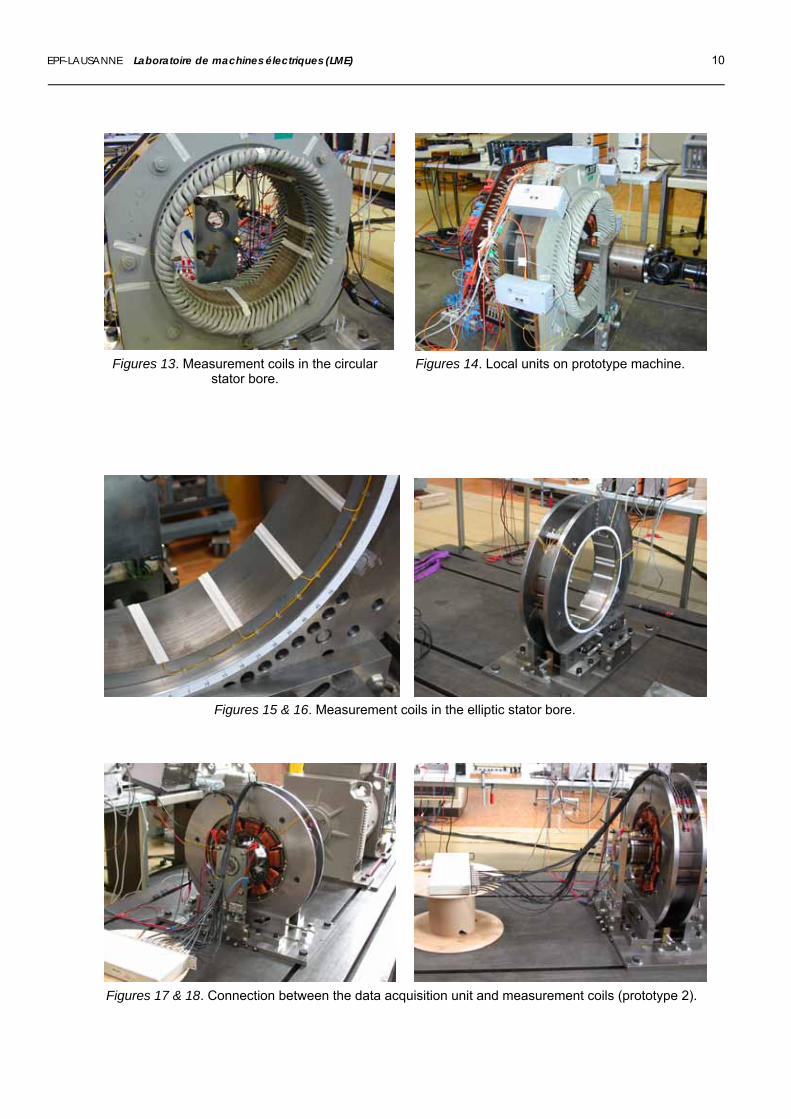
5.1.2. Measurement equipment Measurements have been performed with five air-gap coils arranged on a circular stator. For this test, data acquisition has been carried out using prototype n° 1 (cf. § 2.2.1) (fig. 13 and 14). On the elliptic stator, measurements where performed using fifteen coils and data acquisition prototype n° 2 (cf. § 2.2.2) (fig. 15 to 18).
EPF-LAUSANNE Laboratoire de machines électriques (LME) 10
Figures 13. Measurement coils in the circular
stator bore. Figures 14. Local units on prototype machine.
Figures 15 & 16. Measurement coils in the elliptic stator bore.
Figures 17 & 18. Connection between the data acquisition unit and measurement coils (prototype 2).
EPF-LAUSANNE Laboratoire de machines électriques (LME) 11
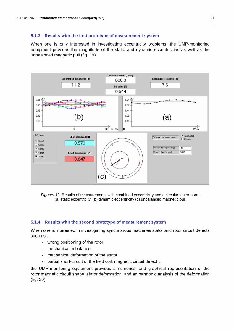
5.1.3. Results with the first prototype of measurement system
When one is only interested in investigating eccentricity problems, the UMP-monitoring equipment provides the magnitude of the static and dynamic eccentricities as well as the unbalanced magnetic pull (fig. 19).
Figures 19. Results of measurements with combined eccentricity and a circular stator bore. (a) static eccentricity (b) dynamic eccentricity (c) unbalanced magnetic pull
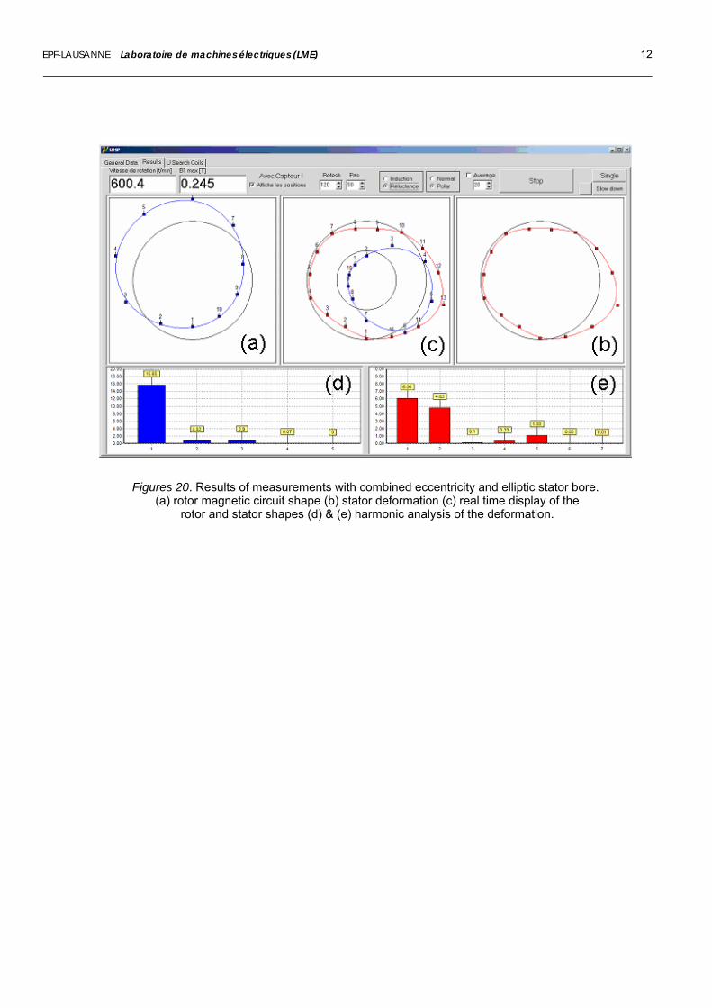
5.1.4. Results with the second prototype of measurement system
When one is interested in investigating synchronous machines stator and rotor circuit defects such as :
- wrong positioning of the rotor, - mechanical unbalance, - mechanical deformation of the stator, - partial short-circuit of the field coil, magnetic circuit defect…
the UMP-monitoring equipment provides a numerical and graphical representation of the rotor magnetic circuit shape, stator deformation, and an harmonic analysis of the deformation (fig. 20).
EPF-LAUSANNE Laboratoire de machines électriques (LME) 12
Figures 20. Results of measurements with combined eccentricity and elliptic stator bore. (a) rotor magnetic circuit shape (b) stator deformation (c) real time display of the
rotor and stator shapes (d) & (e) harmonic analysis of the deformation.
EPF-LAUSANNE Laboratoire de machines électriques (LME) 13
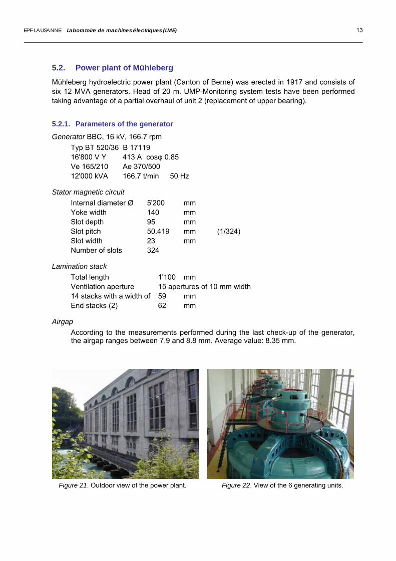
5.2. Power plant of Mühleberg
Mühleberg hydroelectric power plant (Canton of Berne) was erected in 1917 and consists of six 12 MVA generators. Head of 20 m. UMP-Monitoring system tests have been performed taking advantage of a partial overhaul of unit 2 (replacement of upper bearing).
5.2.1. Parameters of the generator
Generator BBC, 16 kV, 166.7 rpm Typ BT 520/36 B 17119 16'800 V Y 413 A cosφ 0.85 Ve 165/210 Ae 370/500 12'000 kVA 166,7 t/min 50 Hz
Stator magnetic circuit Internal diameter Ø 5'200 mm Yoke width 140 mm Slot depth 95 mm Slot pitch 50.419 mm (1/324) Slot width 23 mm Number of slots 324
Lamination stack Total length 1'100 mm Ventilation aperture 15 apertures of 10 mm width 14 stacks with a width of 59 mm End stacks (2) 62 mm
Airgap According to the measurements performed during the last check-up of the generator, the airgap ranges between 7.9 and 8.8 mm. Average value: 8.35 mm.
Figure 21. Outdoor view of the power plant. Figure 22. View of the 6 generating units.

EPF-LAUSANNE Laboratoire de machines électriques (LME) 14
5.2.2. Measurement equipment
Measurements have been completed using five air-gap coils and prototype n° 1 (cf. § 2.2.1).
Figure 23. Local acquisition unit for coil n° 3. Figure 24. Central unit (right) and computer.
5.2.3. Results of measurement
Tests performed revealed very small static and dynamic eccentricities < 3% (fig. 25), but a significant UMP force versus voltage (fig. 26).
Figure 25. Post processing results. Figure 26. Unbalanced magnetic pull vs stator voltage.

EPF-LAUSANNE Laboratoire de machines électriques (LME) 15
5.3. Power plant of Verbois (Geneva)
Verbois hydroelectric power plant construction lasted from 1937 to 1944; it has been renovated in 1985 and in 2000. It comprises four 33 MVA units. Head is 20 m.
5.3.1. Parameters of the generator
Generator ABB, 33 MVA Nominal power 25.75 MW Voltage 9 kV Nominal current 2'117 A Power factor 0.8 Speed 136.4 rpm
Stator magnetic circuit Internal diameter Ø 5'992 mm Total length 1'371 mm Ventilation aperture 10 mm Stacks 60 mm Air-gap 12 mm
Figure 27. Outdoor view of the power plant. Figure 28. Inside general view.
EPF-LAUSANNE Laboratoire de machines électriques (LME) 16
5.3.2. Measurement equipment Measurement were performed using twenty-six air-gap coils and prototype n° 2 (cf. § 2.2.2).
Figure 29. Communication cables for the 26
coils. Figure 30. Data acquisition units and computer.
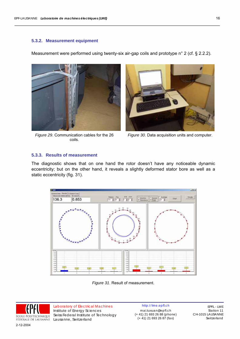
5.3.3. Results of measurement
The diagnostic shows that on one hand the rotor doesn’t have any noticeable dynamic eccentricity; but on the other hand, it reveals a slightly deformed stator bore as well as a static eccentricity (fig. 31).
Figure 31. Result of measurement.
Laboratory of Electrical Machines Institute of Energy Sciences Swiss Federal Institute of Technology Lausanne, Switzerland
http://[email protected]
(+ 41) 21 693 26 88 (phone) (+ 41) 21 693 26 87 (fax)
EPFL - LME Station 11
CH-1015 LAUSANNE Switzerland
2-12-2004