umass amherst information technology design and
TRANSCRIPT

UMass Amherst Information Technology
Design and Construction Specification
June 2021
IT DESIGN & CONSTRUCTION SPECIFICATION – v. 6/2021 27 00 00 PAGE 2
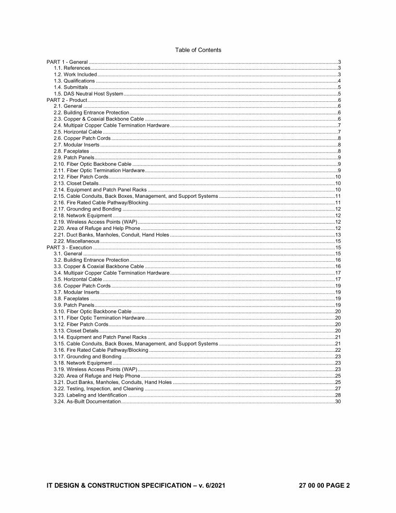
Table of Contents
PART 1 - General .................................................................................................................................................................................. 3 1.1. References.................................................................................................................................................................................3 1.2. Work Included ............................................................................................................................................................................3 1.3. Qualifications .............................................................................................................................................................................4 1.4. Submittals ..................................................................................................................................................................................5 1.5. DAS Neutral Host System .........................................................................................................................................................5
PART 2 - Product ................................................................................................................................................................................... 6 2.1. General ......................................................................................................................................................................................6 2.2. Building Entrance Protection .....................................................................................................................................................6 2.3. Copper & Coaxial Backbone Cable ..........................................................................................................................................6 2.4. Multipair Copper Cable Termination Hardware ........................................................................................................................7 2.5. Horizontal Cable ........................................................................................................................................................................7 2.6. Copper Patch Cords ..................................................................................................................................................................8 2.7. Modular Inserts ..........................................................................................................................................................................8 2.8. Faceplates .................................................................................................................................................................................8 2.9. Patch Panels ..............................................................................................................................................................................9 2.10. Fiber Optic Backbone Cable ...................................................................................................................................................9 2.11. Fiber Optic Termination Hardware ..........................................................................................................................................9 2.12. Fiber Patch Cords..................................................................................................................................................................10 2.13. Closet Details.........................................................................................................................................................................10 2.14. Equipment and Patch Panel Racks ......................................................................................................................................10 2.15. Cable Conduits, Back Boxes, Management, and Support Systems ...................................................................................11 2.16. Fire Rated Cable Pathway/Blocking .....................................................................................................................................11 2.17. Grounding and Bonding ........................................................................................................................................................12 2.18. Network Equipment ...............................................................................................................................................................12 2.19. Wireless Access Points (WAP) .............................................................................................................................................12 2.20. Area of Refuge and Help Phone ...........................................................................................................................................12 2.21. Duct Banks, Manholes, Conduit, Hand Holes ......................................................................................................................13 2.22. Miscellaneous ........................................................................................................................................................................15
PART 3 - Execution ............................................................................................................................................................................. 15 3.1. General ....................................................................................................................................................................................15 3.2. Building Entrance Protection ...................................................................................................................................................16 3.3. Copper & Coaxial Backbone Cable ........................................................................................................................................16 3.4. Multipair Copper Cable Termination Hardware ......................................................................................................................17 3.5. Horizontal Cable ......................................................................................................................................................................17 3.6. Copper Patch Cords ................................................................................................................................................................19 3.7. Modular Inserts ........................................................................................................................................................................19 3.8. Faceplates ...............................................................................................................................................................................19 3.9. Patch Panels ............................................................................................................................................................................19 3.10. Fiber Optic Backbone Cable .................................................................................................................................................20 3.11. Fiber Optic Termination Hardware ........................................................................................................................................20 3.12. Fiber Patch Cords..................................................................................................................................................................20 3.13. Closet Details.........................................................................................................................................................................20 3.14. Equipment and Patch Panel Racks ......................................................................................................................................21 3.15. Cable Conduits, Back Boxes, Management, and Support Systems ...................................................................................21 3.16. Fire Rated Cable Pathway/Blocking .....................................................................................................................................22 3.17. Grounding and Bonding ........................................................................................................................................................23 3.18. Network Equipment ...............................................................................................................................................................23 3.19. Wireless Access Points (WAP) .............................................................................................................................................23 3.20. Area of Refuge and Help Phone ...........................................................................................................................................25 3.21. Duct Banks, Manholes, Conduits, Hand Holes ....................................................................................................................25 3.22. Testing, Inspection, and Cleaning ........................................................................................................................................27 3.23. Labeling and Identification ....................................................................................................................................................28 3.24. As-Built Documentation .........................................................................................................................................................30

IT DESIGN & CONSTRUCTION SPECIFICATION – v. 6/2021 27 00 00 PAGE 3
PART 1 - GENERAL
1.1. REFERENCES
A. Materials and equipment shall be manufactured, installed, and tested as specified in the latest editions of applicable publications, standards, rulings and, determinations of:
1. ANSI - American National Standards Institute. 2. NEC - National Electric Code. 3. NFPA 70 – National Fire Protection Association. 4. ANSI/TIA/EIA-568-C.1, C.2, C.3, Commercial Building Telecommunications Cabling
Standard. 5. ANSI/TIA/EIA-607 Commercial Building Grounding and Bonding Requirements for
Telecommunications. 6. ANSI/ICEA Insulated Cable Engineers Association.
1.2. WORK INCLUDED
A. Perform work and provide material and equipment as shown on Drawings and/or as specified and/or indicated in this Specification(s). The word “provide” as used in this document is to be defined as “provide and install”, unless otherwise qualified.
B. Completely coordinate work of this Section with work of other trades and provide a complete and fully functional installation. It is the responsibility of the Tel/Data Contractor to coordinate and verify that the cable pathways provided by other trades comply with the distance limits and the other pathway requirements specified in the written contract documents. Report any deficiencies to UMass IT. Refer to Cable Pathway requirements immediately below, plus other details in Part 2 and Part 3.
C. Cable pathways from each Tel/Data outlet back to the network switch must be pre-verified as not exceeding the length limit; that is, no installed Cat 6 or Cat 6A cable shall exceed 295’. Also, any conduit run shall not exceed 180-degree total (e.g. two 90-degree bends), without having a readily accessible pull point. “Readily Accessible” means access such as removable acoustic ceiling tiles that, even after the building is occupied, will allow adding or replacing cables. All conduit bends shall be sweep bends with minimum bend radius 3”.
D. Provide a complete set of As-Built Plans showing all cable pathways and all accessible ceilings and cable access panel details to facilitate future cable repair and installation.
E. The word “Plans” is used here and generally to refer to all relevant Contract Drawings, which with the Specifications form complimentary requirements; provide work specified and not shown, and work shown and not specified as though explicitly required by both. Although work is not specifically shown or specified, provide supplementary or miscellaneous items, appurtenances, devices and materials obviously necessary for a sound, secure and complete installation.
F. Give notices, file plans, obtain permits and licenses, pay fees and back charges, and obtain necessary approvals from authorities that have jurisdiction as required to perform work in accordance with all legal requirements and with Specifications, Drawings, Addenda and Change Orders, all of which are part of Contract Documents.
G. Work shall include, but shall not be limited to, the following:
1. Building entrance protection systems. 2. Copper backbone cable (Inside and OSP). 3. IDC termination blocks. 4. Horizontal cable. 5. Patch cables. 6. Modular inserts.

IT DESIGN & CONSTRUCTION SPECIFICATION – v. 6/2021 27 00 00 PAGE 4
7. Faceplates. 8. Patch panels. 9. Fiber optic backbone cable (Inside and OSP). 10. Fiber optic termination enclosures, units and hardware. 11. Equipment racks and associated ladder rack systems. 12. Cable conduits, pathway, management, and support. 13. Fire seal and fire-stopping. 14. Grounding, Bonding and Electrical Protection. 15. Electronic backbone equipment (hubs, switches, routers). 16. Wireless Access Point (AP) devices. 17. Help phones, blue light. 18. Testing (with documentation) of all cabling and devices. 19. Labeling and Documentation of all cabling, outlets, and devices. 20. Shop drawings. 21. Reference to Electrical and Telecom Contract Drawings for additional information. 22. Coordination with all disciplines including, but not limited to, Electrical Contractor, A/V
Contractor, Equipment Contractor, Engineer and Architect.
H. Where conflicts exist within the contract documents, the Contractor shall own the greater quantity and higher quality.
I. Work not included:
1. Peripherals connected to the data cabling infrastructure (servers, workstations, printers, etc.) shall be provided by others.
2. Networking equipment shall be purchased by the project, but provided and installed by IT. 3. In general, all voice equipment connected to telephone cabling infrastructure (phones, faxes
PBX, etc.) shall be provided by others, with any exceptions explicitly specified. All line/equipment cards connecting voice equipment to the voice cabling infrastructure shall be provided by others.
1.3. QUALIFICATIONS
A. The successful bidder shall be thoroughly familiar with the cabling methods set forth in the latest release of the BICSI TDMM's (Building Industry Consulting Services International Telecommunications Distribution Methods Manuals) and unless otherwise specified, shall supervise the installation in accordance with the recommendations and practices outlined in the latest release of the BICSI Telecommunications Cabling Installation Manual.
B. The Telecom cabling contractor shall hold appropriate Commscope/Corning Certification status and therefore be able to provide an Extended Product Warranty program for the copper and fiber cabling system.
C. The successful bidder shall have at least five (5) years’ experience installing and servicing Telecommunication systems, and shall provide a list of completed projects equivalent in size and complexity to this project, with contact names and telephone numbers. Personnel must have experience using a light meter and OTDR.
D. The successful bidder shall submit in writing a list of qualified technicians assigned to this project, including relevant manufacturers training programs completed by each, and years of related experience of each.
E. The successful bidder shall maintain an office or competent technical presence with appropriate testing equipment and replacement parts within 2 hours’ drive time from this project.
IT DESIGN & CONSTRUCTION SPECIFICATION – v. 6/2021 27 00 00 PAGE 5
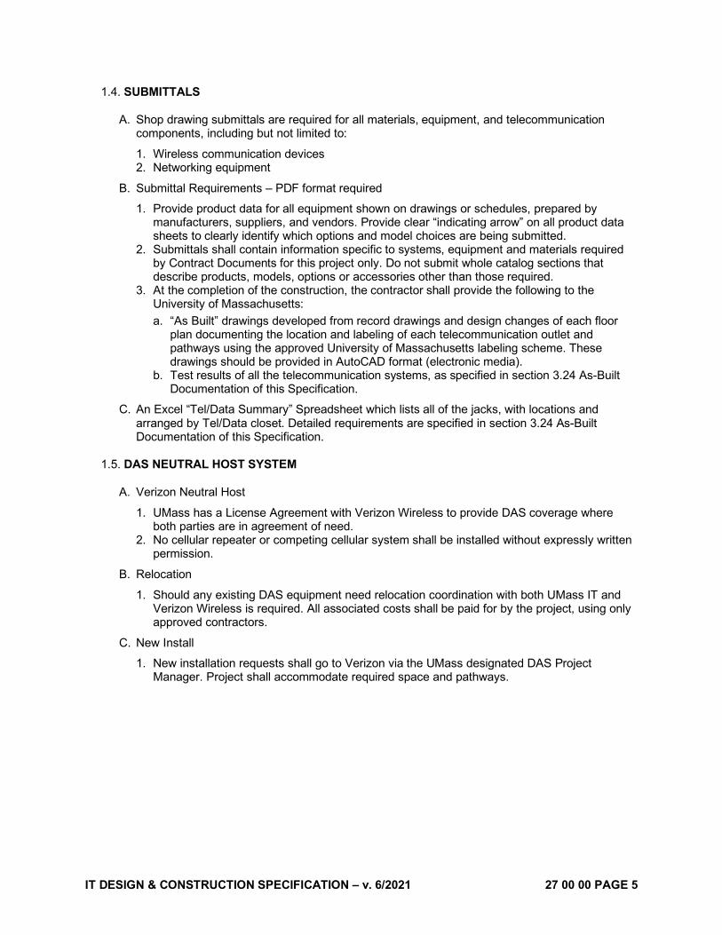
1.4. SUBMITTALS
A. Shop drawing submittals are required for all materials, equipment, and telecommunication components, including but not limited to:
1. Wireless communication devices 2. Networking equipment
B. Submittal Requirements – PDF format required
1. Provide product data for all equipment shown on drawings or schedules, prepared by manufacturers, suppliers, and vendors. Provide clear “indicating arrow” on all product data sheets to clearly identify which options and model choices are being submitted.
2. Submittals shall contain information specific to systems, equipment and materials required by Contract Documents for this project only. Do not submit whole catalog sections that describe products, models, options or accessories other than those required.
3. At the completion of the construction, the contractor shall provide the following to the University of Massachusetts: a. “As Built” drawings developed from record drawings and design changes of each floor
plan documenting the location and labeling of each telecommunication outlet and pathways using the approved University of Massachusetts labeling scheme. These drawings should be provided in AutoCAD format (electronic media).
b. Test results of all the telecommunication systems, as specified in section 3.24 As-Built Documentation of this Specification.
C. An Excel “Tel/Data Summary” Spreadsheet which lists all of the jacks, with locations and arranged by Tel/Data closet. Detailed requirements are specified in section 3.24 As-Built Documentation of this Specification.
1.5. DAS NEUTRAL HOST SYSTEM
A. Verizon Neutral Host
1. UMass has a License Agreement with Verizon Wireless to provide DAS coverage where both parties are in agreement of need.
2. No cellular repeater or competing cellular system shall be installed without expressly written permission.
B. Relocation
1. Should any existing DAS equipment need relocation coordination with both UMass IT and Verizon Wireless is required. All associated costs shall be paid for by the project, using only approved contractors.
C. New Install
1. New installation requests shall go to Verizon via the UMass designated DAS Project Manager. Project shall accommodate required space and pathways.

IT DESIGN & CONSTRUCTION SPECIFICATION – v. 6/2021 27 00 00 PAGE 6
PART 2 - PRODUCT
2.1. GENERAL
A. All UTP cabling shall meet or exceed all requirements in this specification, ANSI/TIA/EIA S-80-576, that are applicable to four-pair inside wiring cable. Where any portion of a cable runs through a plenum space within the building use plenum-rated cable. If there are no plenum spaces, use CMR type cables. Generally, the campus uses ducted supply and ducted return HVAC system so CMR is sufficient, and it is preferred.
B. Manufacturer and part numbers are indicated throughout the Specification to establish quality and performance characteristics and strict minimum performance requirements of individual products and the precise matching of tested and proven system combinations.
C. Where only one manufacturer or product/model is designated, and if there is no added note offering “or approved equal”, the particular product is likely to be specifically covered as a UMass standard installation requirement. Any deviation from the specified components/manufacturers must be clearly noted as such on the product submittal, and be explicitly and specifically approved by a UMass IT Network Communications Project Engineer.
D. Any submittal deviating from the Specification will require documentation proving equivalent performance to the specified products/system combinations. Final acceptance testing and warrantees must strictly equal or exceed the performance specifications detailed herein.
2.2. BUILDING ENTRANCE PROTECTION
A. Building Entrance Protection Units shall be comprised of Circa Telecom p/n: 1880B1-100K: 100 PAIR - INDOOR BET with 25' OSP AIR CORE CABLE STUB/110 - NO COVER, or approved equal. These shall be spliced onto the OSP cable.
1. Instances where a telephone node, on the far end of a copper OSP, cannot accommodate a wall mounted protector such as the Circa specified above the original building protection unit style shall be used. Bourns model C(G)-391, or approved equal, with gold connectors and 22 AWG stub, also gets spliced onto the OSP cable.
B. Protector modules shall be 5-pin Circa Telecom p/n: 3B1S-300. Install protector modules in all sockets.
C. Cable protectors for jacks outside of the building:
1. Data jacks shall use a SurgeGate Cat6-75/PoE-RJ45 modular protector p/n: 2090-220-30B 2. Telephone jacks shall use a two pair Circa Telecom modular protector
a. Analog lines p/n: 502-A350 b. Digital lines p/n: 502-D300
3. Coax protectors, for data jacks over 90m using coax extenders, shall use a single port F-type grounding block rated up to 3GHz. Acceptable manufacturer INFINITe, Show Me Cables p/n:253 , or approved equal.
D. Provide building entrance protection units at the Campus tie-in points for the origin of the phone feeder cable, at both ends. The Campus phone cable tie-in point shall be designated in the plans.
2.3. COPPER & COAXIAL BACKBONE CABLE
A. Copper Backbone Cable
1. Outside plant multipair copper cable shall be 24 AWG, PE-89 type, foam skin, filled core, CALPETH type, made by Superior Essex or approved equal.

IT DESIGN & CONSTRUCTION SPECIFICATION – v. 6/2021 27 00 00 PAGE 7
2. Where OSP cable is spliced in manholes, splice connector modules shall be 710-SC1-25 made by 3M. Splice closures used in manholes shall be UCN manufactured or equal sized for cable, and encapsulate filled.
3. Where OSP multipair copper phone cable enters buildings, it shall be spliced to DIW riser-rated backbone cable. Riser rated splice closures shall be used to contain such splices.
4. Inside backbone cable shall be Superior Essex, Belden or Commscope, and plenum-rated wherever specifically required by code, but riser-rated if no plenum spaces involved. a. Instances where this is installed in a building that also serves as a telephone node the 66
blocks in the node must have all pins isolated from each other. Siemon p/n: S66M1-100
B. Coaxial Cable
1. Outside plant coaxial cable shall be .750 Coax Cable, flooded aluminum, T10 1 GHz series or approved equal.
2. Where OSP coaxial cable is spliced in manholes, splice connector modules shall be 750 Splice Connector for Commscope P3 & TFC T10. Splice shall be sealed with CFTV-1700 heat shrink tube for .750 and .875 Cable, after inspection and testing.
3. Where OSP coaxial cable enters buildings, it shall be secured to 4’x4’x3/4” pressure treated plywood.
4. Inside coaxial backbone cable a. Shall be RG11-60PWR-M RG-11 60% Braid Plenum 1000 ft Reel, White, and plenum-
rated wherever specifically required by code, but RG11-60RBR-M RG-11 60% Braid 1000 ft Reel, Black, if no plenum spaces involved.
2.4. MULTIPAIR COPPER CABLE TERMINATION HARDWARE
A. Provide IDC 110 block termination hardware to terminate all of the copper voice riser in the MDF Room. Manufactured by Belden, Leviton or Commscope.
1. The IDC 110 termination frames in the MDF shall be a cross-connect point. There shall be a DIW riser rated cable to each IDF as well as to the passive cabling rack in the MDF. See sections 2.9 and 3.9 for Patch Panels products and termination instructions, respectively.
2.5. HORIZONTAL CABLE
A. Station cables shall be 23AWG solid copper conductor, 4-pair, 100W balanced UTP, and tested to 550 MHz enhanced category 6 cables with a blue jacket. Cable shall be marked suitable for its purpose and meet or exceed the mechanical specifications in ANSI/TIA-568.2-D.
1. Non-plenum rated: a. Commscope CS37R, p/n: UN884026814/10 b. Hitachi Cat 6 Plus (riser), p/n: 30024-8-BL2
2. Plenum Rated: a. Commscope CS37P, p/n: UN874043004/10 b. Hitachi Cat 6 Plus (plenum), p/n: 30025-8-BL2
B. Locations where 10Gb dedicated data connections are necessary shall use the products in the section directly after this, category 6A as used for wireless APs, for station cables.
C. Wireless AP cables shall be 23AWG solid copper conductor, 4-pair, 100W balanced UTP, and tested to 660 MHz enhanced category 6A cables with a green jacket. Cable shall be marked suitable for its purpose and meet or exceed the mechanical specifications in ANSI/TIA-568.2-D.
1. Non-plenum rated: a. Commscope CS44R p/n: UN884029304/10 b. Hitachi Cat 6A Supra (riser), p/n: 30222-8-GR3
2. Plenum Rated:
IT DESIGN & CONSTRUCTION SPECIFICATION – v. 6/2021 27 00 00 PAGE 8
a. Commscope CS44P p/n: UN874035914/10 b. Hitachi Cat 6A Supra (plenum), p/n: 30218-8-GR3
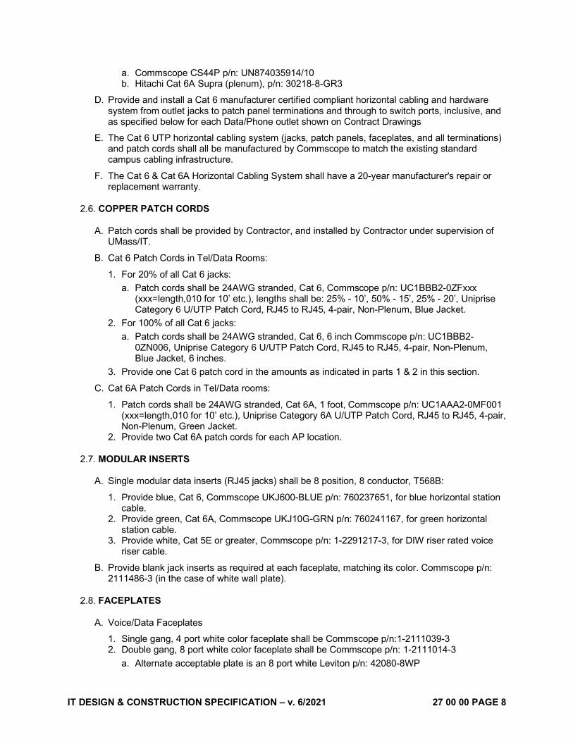
D. Provide and install a Cat 6 manufacturer certified compliant horizontal cabling and hardware system from outlet jacks to patch panel terminations and through to switch ports, inclusive, and as specified below for each Data/Phone outlet shown on Contract Drawings
E. The Cat 6 UTP horizontal cabling system (jacks, patch panels, faceplates, and all terminations) and patch cords shall all be manufactured by Commscope to match the existing standard campus cabling infrastructure.
F. The Cat 6 & Cat 6A Horizontal Cabling System shall have a 20-year manufacturer's repair or replacement warranty.
2.6. COPPER PATCH CORDS
A. Patch cords shall be provided by Contractor, and installed by Contractor under supervision of UMass/IT.
B. Cat 6 Patch Cords in Tel/Data Rooms:
1. For 20% of all Cat 6 jacks: a. Patch cords shall be 24AWG stranded, Cat 6, Commscope p/n: UC1BBB2-0ZFxxx
(xxx=length,010 for 10’ etc.), lengths shall be: 25% - 10’, 50% - 15’, 25% - 20’, Uniprise Category 6 U/UTP Patch Cord, RJ45 to RJ45, 4-pair, Non-Plenum, Blue Jacket.
2. For 100% of all Cat 6 jacks: a. Patch cords shall be 24AWG stranded, Cat 6, 6 inch Commscope p/n: UC1BBB2-
0ZN006, Uniprise Category 6 U/UTP Patch Cord, RJ45 to RJ45, 4-pair, Non-Plenum, Blue Jacket, 6 inches.
3. Provide one Cat 6 patch cord in the amounts as indicated in parts 1 & 2 in this section.
C. Cat 6A Patch Cords in Tel/Data rooms:
1. Patch cords shall be 24AWG stranded, Cat 6A, 1 foot, Commscope p/n: UC1AAA2-0MF001 (xxx=length,010 for 10’ etc.), Uniprise Category 6A U/UTP Patch Cord, RJ45 to RJ45, 4-pair, Non-Plenum, Green Jacket.
2. Provide two Cat 6A patch cords for each AP location.
2.7. MODULAR INSERTS
A. Single modular data inserts (RJ45 jacks) shall be 8 position, 8 conductor, T568B:
1. Provide blue, Cat 6, Commscope UKJ600-BLUE p/n: 760237651, for blue horizontal station cable.
2. Provide green, Cat 6A, Commscope UKJ10G-GRN p/n: 760241167, for green horizontal station cable.
3. Provide white, Cat 5E or greater, Commscope p/n: 1-2291217-3, for DIW riser rated voice riser cable.
B. Provide blank jack inserts as required at each faceplate, matching its color. Commscope p/n: 2111486-3 (in the case of white wall plate).
2.8. FACEPLATES
A. Voice/Data Faceplates
1. Single gang, 4 port white color faceplate shall be Commscope p/n:1-2111039-3 2. Double gang, 8 port white color faceplate shall be Commscope p/n: 1-2111014-3
a. Alternate acceptable plate is an 8 port white Leviton p/n: 42080-8WP

IT DESIGN & CONSTRUCTION SPECIFICATION – v. 6/2021 27 00 00 PAGE 9
B. Wall phone faceplates
1. Use the same single gang 4 port faceplate specified above. 2. Do not use standard wall plates as these are not compatible with phones used on campus.
2.9. PATCH PANELS
A. At the network equipment rooms the horizontal cables shall terminate on patch panels in racks that accept Commscope KJ jacks with a window for printed labels to be inserted. Both 24 and 48 port patch panels shall be used in each installation.
1. Modular PnP 24 port rack mountable patch panel: Commscope CPP-UDDM-KJ-1U-24 p/n: 760237052
2. Modular PnP 48 port rack mountable patch panel: Commscope CPP-UDDM-KJ-2U-48 p/n: 760241547
3. Labeling window: Commscope p/n: 760199570
2.10. FIBER OPTIC BACKBONE CABLE
A. General
1. The cable shall meet all requirements stated in this Specification. The cable shall meet the requirements of the United States Department of Agriculture Rural Utilities Service (RUS) 7 CFR 1755.900 and the ANSI/ICEA Standard for Fiber Optic Outside Plant Communications Cable, ANSI/ICEA S-87-640-1992.
2. ACCEPTABLE MANUFACTURERS: Corning, Commscope, Superior Essex, but all cables must be manufactured with and identified as Corning glass.
B. OSP
1. Cables shall meet or exceed TIA/EIA 568-C specifications for performance and be indoor/outdoor rated, all dielectric design, with fully water blocked core. Cables shall be OFNR rated with dry loose tube cables. Sized as indicated on Plans.
C. ISP
1. All fiber optic cables shall meet or exceed TIA/EIA 568-B specifications and UL 910 for performance. All fiber optic cables shall be UL listed OFNR rated with fibers individually wrapped in a color-coded 900-micron tight buffer.
D. Associated Products
1. All fiber cables installed in outside duct banks shall be installed in textile innerduct such as 3-cell Maxcell sized for each particular duct, or approved equal.
2. Where installed indoors, all fiber shall be installed in white 1” innerduct, riser-rated.
2.11. FIBER OPTIC TERMINATION HARDWARE
A. MDF/IDF Termination Locations
1. When terminated in an equipment rack, fiber shall be spliced to LC duplex type connectors with fusion splice pigtails installed in Corning termination cassettes (CCH cassettes p/n: CCH-CS12-A9-P00REor CCH-CS24-A9-P00RE).
2. Fiber shall be terminated in equipment racks using cabinets appropriately sized. Fiber cabinets shall be Corning CCH cabinets, that accept CCH cassettes, Corning p/n: CCH-XXX (XXX = size of cabinet: 01U, 02U, 03U, 04U) large enough to terminate all fiber entering the room.

IT DESIGN & CONSTRUCTION SPECIFICATION – v. 6/2021 27 00 00 PAGE 10
B. Other Termination Locations
1. Where fiber terminations cannot be terminated in an equipment rack, a wall-mounted enclosure unit shall be used. In such cases, provide Century 72 port enclosures of sufficient capacity, with UMass standard key/locking where indicated. 72 port fiber termination enclosure, Century p/n: FCP 72ST UMLS (No substitutes, must match existing arrays)
2. When terminating in Century cabinets, fiber shall be spliced to LC pigtails. 3. Splice trays shall be FIS p/n: F1-SPL12 or F1-SPL24, or approved equal.
2.12. FIBER PATCH CORDS
A. Provide fiber optic patch cords for cross-connection to backbones or active equipment of type LC to LC duplex. Quantity: equal in quantity to enable patching 40% of the fiber terminations at each location. Lengths: 80% to be 1.5 meters, and 20% 2 meters.
B. They shall be of type: bend-insensitive, short boot, LC-LC duplex SM Corning fiber jumpers.
2.13. CLOSET DETAILS
A. Provide sufficient cooling for each IT closet. Coordinate with UMass IT for heat loads.
B. Provide a dedicated 208Y/ 120VAC (4-wire) 100A panel with space for eighteen (18) 20A breakers.
C. Provide one (1) NEMA type L5-20R twist lock receptacle at the top rear of each vertical wire manager 6” above the ladder rack.
a. Where a wire manager is shared between two equipment racks place two (2) of these receptacles.
D. Provide one IT closest label per closet, printed on standard 8.5”x11” paper and placed in adhesive backed plastic sheet holders.
E. Provide campus standard card access equipment at each IT location, to be specified by the Card Access System Administrator.
F. Backboards
1. Plywood, AC grade fire-retardant treated ¾” thick by 48” by 96”. 2. Backboard shall be painted with 2 coats of paint, color blue. Color: Sherwin Williams
“Freshwater” #6774 or approved similar color.
G. Each closet shall be simply labelled “IT” if a room label is installed outside the door.
H. Floor finish shall be smooth, dust-free, and not susceptible to static electrical build-up. Acceptable finishes are low static composition tile, static dissipating tile (SDT), or sealed concrete.
2.14. EQUIPMENT AND PATCH PANEL RACKS
A. Floor mounted racks shall be 7'H x 19"W, manufactured by Chatsworth or approved equal. p/n: 46353-703.
B. Vertical wire management shall be 6” Chatsworth p/n: 30162-703 CCS Combination Cabling Section installed.
C. Equipment racks stacked next to each other shall have a 10” equivalent wire manager between them. Chatsworth p/n: 30163-703.
D. Horizontal wire management shall be 1U Commscope p/n: 760038240.
E. Each rack shall have a double shelf (front/back) installed at the lowest level for placing UPS units. Chatsworth p/n: 11164-719 or approved equal.

IT DESIGN & CONSTRUCTION SPECIFICATION – v. 6/2021 27 00 00 PAGE 11
2.15. CABLE CONDUITS, BACK BOXES, MANAGEMENT, AND SUPPORT SYSTEMS
A. Cable Conduits and Pathway
1. Conduits shall be EMT of a minimum 1” diameter, sized up as needed. 2. All EMT conduit ends require a protective bushing.
B. Back Boxes
1. All faceplate and wireless access point back boxes shall be 4-11/16” steel square outlet boxes. a. Faceplates
i. Single gang faceplates shall have a single gang reducer plate. ii. Double gang faceplates shall have a double gang reducer plate.
b. Wireless Aps i. Wall mount locations shall have a single gang reducer plate. ii. Ceiling mount locations shall leave the back box open.
C. Cable Runway and Ladder Rack System
1. 12” and 18” Cable Runway and Ladder Rack products shall be manufactured by Chatsworth p/n: 10250-712 or 10250-718 or approved equal by Cooper B-Line or Homaco.
2. Ladder racks must secure to the equipment racks below with an elevation bracket. Chatsworth p/n: CW 10506-706 or CW 10506-712
3. Cable transition waterfalls shall be able to be located anywhere on the ladder rack, not just on rungs, therefore use Chatsworth p/n: 14304-712 or 14304-718
4. Provide all components to make a complete system. a. Such other components shall include: Butt Splice kits, Wall Angle Support Brackets,
Junction Splice kit; Threaded ceiling kit; Grounding kit; Mechanical Fasteners to connect to the top of Equipment Racks and Cable Drop-Outs.
D. Wire mesh Flextray Cable Support System
1. Provide Wire Mesh Cable Tray systems where indicated on Plans. Wire Mesh Cable Tray systems shall be Copper B-Lines Flextray, p/n: FT2X4X10 or approved equal.
2. Provide all associated supports and system fittings required to make a complete pathway system wherever indicated on Plans. Install according to manufacturer’s installation manual.
E. Cable Supports and Management
1. Cable hangers shall be open-top cable supports (J-Hooks), 2" diameter loop, Brady manufactured or approved equal.
2. J-Hook cable hangers shall be rated for Cat 6 support. 3. J-Hook system support bar shall be Caddy manufactured or equal. 4. Cable management straps shall be of the Velcro variety, Siemon p/n: VCM-25-06-01 or
VCM-25-12-1 or approved equal.
2.16. FIRE RATED CABLE PATHWAY/BLOCKING
A. Provide fire-rated cable pathway units wherever station cables are emerging from Tel/Data closets needing a fire-stopped sleeve arrangement. The fire-rated pathway should have a cable capacity equal to double the quantity of existing cables emerging from the closet. Use EZ-Path p/n: EZDP33FWS, Hilti CP 653, or approved equal.
B. Any fire blocking material, in other fire rated walls, in shall remain malleable after installation to remain easily re-enterable. Hardening spray foams will not be accepted and may violate cabling product warranties. Approved materials:

IT DESIGN & CONSTRUCTION SPECIFICATION – v. 6/2021 27 00 00 PAGE 12
1. Firestop foam plug, use Hilti CFS-PL or approved equal. 2. Firestop foam putty, use Hilti CP 618 or approved equal.
C. Spray foam fire blocking is not permitted under any circumstances in conduits.
2.17. GROUNDING AND BONDING
A. Provide a suitable telecommunications wall mounted ground bus bar (TGB) in every Tel/Data Room for equipment as required per ANSI/TIA/ EIA-607 (telecommunications grounding), IEEE Emerald Green book and NEC requirements. 1. Suitably sized bus bars such as Copper B-Lines p/n: SBTMBG12 or SBTMBG20 or
approved equal.
B. All grounding wire shall be:
1. Bus bars to equipment/ladder racks shall be green 6 AWG copper. 2. Bus bars to building system ground at main electrical service entrance shall be green 4
AWG copper. 3. Bus bars to steel frame of the building shall be green 2 AWG copper.
C. Fittings 1. All connections shall be made using two-hole long barrel compression lugs. 2. Any grounding conductors connected to each other shall be done so with an irreversible
crimp connector.
2.18. NETWORK EQUIPMENT
A. UMass IT shall determine needs and procure equipment based on jack counts to each closet to be given by project designers.
B. Networking equipment by others shall not be installed interfacing with the UMass IT network.
1. See Section 3.18 Network Equipment for more detail.
C. The Project shall pay for equipment.
2.19. WIRELESS ACCESS POINTS (WAP)
A. UMass IT shall determine needs and procure equipment based on final 100% DD floor plans.
B. The Project shall pay for the equipment.
C. All WAP locations shall have a male RJ-45 connector on the 6A cable.
2.20. AREA OF REFUGE AND HELP PHONE
A. Area of Refuge and Emergency Phones shall be GAI-Tronics type RED ALERT® Emergency Telephone Model 398-001. This is a Flush-Mount Emergency Telephone with Single-Button Auto-dial, CALL Pushbutton and Keypad. Install where noted on Plans.
B. Mounting
1. Indoor flush mount enclosure shall be the one included in the box with the flush mount help phone. a. In retrofit situations GAI-Tronics offers a custom enclosure with larger, ¾”, flanges for
easier installation p/n: GTB14031. 2. Exterior surface mount enclosure shall be GAI-Tronics p/n: 236-001YL.
IT DESIGN & CONSTRUCTION SPECIFICATION – v. 6/2021 27 00 00 PAGE 13
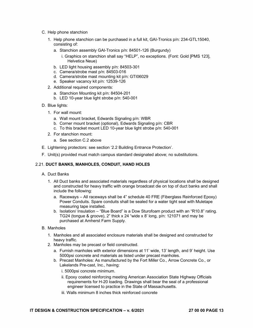
C. Help phone stanchion
1. Help phone stanchion can be purchased in a full kit, GAI-Tronics p/n: 234-GTL15040, consisting of: a. Stanchion assembly GAI-Tronics p/n: 84501-126 (Burgundy)
i. Graphics on stanchion shall say “HELP”, no exceptions. (Font: Gold [PMS 123], Helvetica Neue)
b. LED light housing assembly p/n: 84503-301 c. Camera/strobe mast p/n: 84503-016 d. Camera/strobe mast mounting kit p/n: GTI06029 e. Speaker vacancy kit p/n: 12539-126
2. Additional required components: a. Stanchion Mounting kit p/n: 84504-201 b. LED 10-year blue light strobe p/n: 540-001
D. Blue lights:
1. For wall mount: a. Wall mount bracket, Edwards Signaling p/n: WBR b. Corner mount bracket (optional), Edwards Signaling p/n: CBR c. To this bracket mount LED 10-year blue light strobe p/n: 540-001
2. For stanchion mount: a. See section C.2 above
E. Lightening protectors: see section ‘2.2 Building Entrance Protection’.
F. Unit(s) provided must match campus standard designated above; no substitutions.
2.21. DUCT BANKS, MANHOLES, CONDUIT, HAND HOLES
A. Duct Banks
1. All Duct banks and associated materials regardless of physical locations shall be designed and constructed for heavy traffic with orange broadcast die on top of duct banks and shall include the following: a. Raceways – All raceways shall be 4” schedule 40 FRE (Fiberglass Reinforced Epoxy)
Power Conduits. Spare conduits shall be sealed for a water tight seal with Muletape measuring tape installed.
b. Isolation/ Insulation – “Blue Board” is a Dow Sturofoam product with an “R10.8” rating. TG24 (tongue & groove), 2” thick x 24 “wide x 8’ long, p/n: 121071 and may be purchased at Amherst Farm Supply.
B. Manholes
1. Manholes and all associated enclosure materials shall be designed and constructed for heavy traffic.
2. Manholes may be precast or field constructed. a. Furnish manholes with exterior dimensions at 11’ wide, 13’ length, and 9’ height. Use
5000psi concrete and materials as listed under precast manholes. b. Precast Manholes: As manufactured by the Fort Miller Co., Arrow Concrete Co., or
Lakelands Pre-cast, Inc., having: i. 5000psi concrete minimum. ii. Epoxy coated reinforcing meeting American Association State Highway Officials
requirements for H-20 loading. Drawings shall bear the seal of a professional engineer licensed to practice in the State of Massachusetts.
iii. Walls minimum 8 inches thick reinforced concrete

IT DESIGN & CONSTRUCTION SPECIFICATION – v. 6/2021 27 00 00 PAGE 14
iv. Top slab minimum 8 inches thick reinforced concrete. v. Bottom slab minimum 12 inches thick reinforced concrete. vi. Sealed joints.
c. Equip manholes with a puling hook opposite to each conduit entrance. Construct a hook of 0.875” galvanized stock with 3” diameter eye and 8 inches for anchoring in manhole wall.
d. Provide a sump drain and sloped floor in manhole per drawing. e. Brick shall comply with the specifications for Sewer Brick, Grade MS, ASTM C32. f. Mortar: One part of Portland cement to two parts sand, mixed with water for proper
consistency. g. Waterproofing for Bricked-up throat: Single component, rubber reinforced asphalt
elastomeric coating, ASTM D-4586 Type 1 and ASTM D-4479 Type I. 3. Watertight Manhole Frames and Covers
a. Design of each shall be the same throughout the project unless otherwise specified or indicated on the drawings.
b. Lid and frame – Shall be Heavy duty Large Manhole Frames with Base Flange and Solid 44” Lid with 6” offset removable 22” Center Lid, each/both lids shall have 2 each 1” diameter holes 5” from edge of lids, 2 each Type C Drop Handles and with “TELECOM” and TMH- (**) Lettering on large Lid. (** will be designated by the UMass IT Department) as manufactured by NEENAH Foundry p/n: R-1741-E.
4. Cable Support System a. Cable support systems must be heavy duty, non-metallic. Cable support arms shall be
20” minimum 12” in length. 5. Installation:
a. Bricked-up throat: Mortar brick into place. Set manhole frame with mortar. Waterproof exterior of throat with minimum of 3/32 inch of bituminous plastic cement coating.
b. Cable Supports: Install racks, support arms and insulators of size and number to provide one insulator (or equivalent space of nonmetallic support arms) on each cable support assembly for each conduit entering manhole.
c. Spare Conduits – All spare conduits shall have NEPTCO WL1800 Woven 3/8” (Aramid) MULETAPE installed and shall be sealed for a water tight seal. (3,000 ft min order)
d. Cable Racks – Cable racks shall be Heavy Duty Non-Metallic. Cable support arms shall be 20” minimum 12” in length.
6. Waterproofing additive: a. When purchasing or constructing manholes, please use Krystol Internal membrane
additive to the concrete. 7. Drainage – Manholes shall include a sump with removable vented drain cover drained to the
campus storm-drain system. 8. Ladder
a. Manhole ladders shall be fiberglass designed, assembled and installed to OSHA standards. Manufactured by Empire Fiberglass Products Inc.
9. Duct Bank Terminators a. Duct Bank Terminators shall be as manufactured by Formex Manufacturing Inc.
10. Pulling irons shall be 12” hot dipped 7/8” pulling irons with cross bar and retaining. 11. Hardware – All hardware shall be stainless steel.
C. Conduits
a. For direct bury conduit, provide two (2) 2” schedule 40 conduits, one for redundancy, unless otherwise noted.
b. Place hand hole after 270 degrees of conduit bend. c. Place orange “Telecommunications” metallic tracing tape 18” above buried conduits.

IT DESIGN & CONSTRUCTION SPECIFICATION – v. 6/2021 27 00 00 PAGE 15
D. Hand holes shall be Heavy Traffic Tier 22, stackable, open bottom with cover engraved “TELECOM” as manufactured by:
1. Quazite a. 13 X 24
i. Box, p/n: PG1324BA18 ii. Cover, p/n: PG1324HH0042
b. 17 X 30, i. Box, p/n: PG1730BA18 ii. Cover, p/n: PG1730HH0042
2. NewBasis a. 13 X 24 assembly, p/n: PCA132418-20066, with “TELECOM” engraved. b. 17 X 30 assembly, p/n: PCA173018-20066, with “TELECOM” engraved.
2.22. MISCELLANEOUS
A. Provide one aluminum 4’ stepladder in every UMass IT Room. Stencil on each ladder “UMass IT, Room # xx”. Use 3” lettering.
PART 3 - EXECUTION
3.1. GENERAL
A. All telecommunication outlets shall be T568B wiring configuration.
B. All UTP cabling shall meet or exceed all requirements in this Specification, ANSI/TIA/EIA S-80-576 (pair color code, etc.), that are applicable to four-pair inside wiring cable for plenum spaces within a building.
C. Coordinate all work with all contract documents including but not limited to:
1. Architectural floor plans and equipment layouts. 2. Electrical contract documents. 3. Mechanical equipment.
D. Coordinate all work with all on-site contractors including, but not limited to:
1. UMass IT. 2. Electrical Contractor. 3. Other contractors and consultants.
E. Refer to Electrical Contract Drawings for pathways including sleeves, conduits, cable tray to be utilized by this contractor.
F. Refer to Electrical and Telecommunications Contract Drawings for additional information.
G. Cooperate and coordinate with work of other sections in executing work of this section.
H. Perform work so that progress of entire project including work of other sections is not interfered with or delayed. Obtain detailed installation information from all manufacturers of equipment provided under other sections.
I. Materials and Workmanship:
1. Work shall be executed in a professional manner, shall be neat, plum, parallel to the building structure, and perpendicular to all electronics and associated cabling when complete. All
IT DESIGN & CONSTRUCTION SPECIFICATION – v. 6/2021 27 00 00 PAGE 16
work shall adhere to the standards as set forth in this Specification. Maintain maximum headroom at all times. Do not run work exposed unless shown exposed on drawings.
2. Material and equipment shall be new and installed according to manufacturer's recommended best practices so that completed installation shall operate safely and efficiently, and be neatly installed.
J. The contractor owns the greater quantity and better quality where conflicts exist.
K. Any reference to telecommunication outlet shall indicate faceplate, modular insert, termination, cabling, labeling, testing, etc.
L. All cabling shall be terminated at both ends unless noted otherwise.
M. All cables shall be clearly, permanently and robustly labeled at both ends, with machine printed labels.
N. To minimize EMI interference, maintain maximum separation of tel/data cabling from power wiring and conduits wherever feasible; 6” separation generally acceptable. Maintain 12” separation of tel/data cabling from fluro ballasts and wherever feasible.
O. Continuity of Services: Do not interrupt existing services. Existing services shall remain operational at all times. If the existing services need to be disrupted for any reason the contractor shall contact the Owner (representative to be announced at a later date) and schedule the aforementioned shutdown. The contractor shall schedule the shutdown with the Owner a minimum of 48 hours in advance.
3.2. BUILDING ENTRANCE PROTECTION
A. Provide layout proposals to UMass IT Network Communications Project Engineer for approval, before installing the BEP termination modules at each end of the Outside Plant Cable.
B. Provide adequate cable management capacity for future crosswire connections from the BEP to station and riser terminations.
C. Locate BEP on wall in MDF room.
D. Any new copper backbone or existing copper backbone requiring re-splicing should receive BEP.
E. Data, camera, & phone jacks outside of the building.
1. Jacks on the roof, on an arm protruding off the building, or exterior to the building envelope require protection as follows: a. Data and camera jacks shall have a lightening protector in the serving IT closet, mounted
to the plywood wall, and labelled with the jack number. b. Phone jacks shall have a lightening protector in the serving IT closet as well as at the
device end (e.g. Help Phone), mounted to the plywood wall or affixed in a protected space outside, rated for analog or digital depending on the application, and labelled with the jack number.
c. Data jacks further than 90m away using coax network extenders shall have: i. The standard category cable lightening protector to protect the switch in the serving IT
closet as described above in this section. ii. A coax grounding block in the serving IT closet, mounted to the plywood wall, and
labelled with the jack number. 2. Jacks for devices on the building envelope (e.g. data, Help Phone, camera) do not require a
protector.
3.3. COPPER & COAXIAL BACKBONE CABLE
A. Copper Backbone Cable

IT DESIGN & CONSTRUCTION SPECIFICATION – v. 6/2021 27 00 00 PAGE 17
1. Provide outside plant cable and inside plant cable as detailed in the riser diagram. 2. Provide adequate and reasonable service loops, 20’ after every 1000’ of duct bank. Provide
20’ of service slack in the last manhole before entering any building. Provide 15’ of service slack in the cable entrance room.
3. Provide durable waterproof plastic labels on every new cable with 1” high machine lettering; 2 labels per cable, per manhole, one at each location the cable leaves the manhole, 2 feet from the exit. UMass IT will provide cable ID names (that should be printed by the Contractor).
B. Coaxial Cable
1. Provide outside coaxial plant cable and inside coaxial plant cable as detailed in the riser diagram.
2. Provide adequate and reasonable service loops, 20’ after every 1000’ of duct bank. Provide 20’ of service slack in the last manhole before entering any building. Provide 15’ of service slack in the cable entrance room.
3. Provide durable waterproof plastic labels on every new cable with 1” high machine lettering; 2 labels per cable, per manhole, one at each location the cable leaves the manhole, 2 feet from the exit. ID names will be CABLE 1 and CABLE 2(that should be printed by the Contractor).
3.4. MULTIPAIR COPPER CABLE TERMINATION HARDWARE
A. Provide IDC 110 block termination hardware to terminate all of the copper voice riser in the MDF Room on the wall.
B. At the other end of the riser cables, provide rack-mountable plug and play patch panels for all cable pairs in multiples of 48 (same as specified for station cables) for all voice riser cables, terminating one pair onto each modular jack insert. See section 2.7 Modular Inserts.
1. Leave the end count pairs of the riser cable unterminated and coiled with slack behind the patch panel (e.g. a 50 pair cable = 48 port patch panel, means pairs 49&50 left coiled) (e.g. a 100 pair cable = (2) 48 port patch panels, means pairs 97, 98, 99, & 100 left coiled)
C. Provide split 3” D-rings on all sides of the IDC 110 frames for management of crosswire.
D. Provide labeling strips for each 110 frame as noted in section 3.23 Labeling and Identification:
3.5. HORIZONTAL CABLE
A. Provide horizontal voice/data station cables from each work station outlet back to its designated and/or nearest Tel/Data Room and terminate in a patch panel rack.
1. Cables dressed into the patch panels at the equipment room shall come into the patch panel from only one direction per patch panel. Patch panel cable dressing should alternate direction for every adjacent patch panel (e.g. top patch panel cables come in from left, the patch panel below it cables come in from right, etc.).
B. Provide one (1) horizontal Cat 6 cable from each modular insert to its corresponding RJ45 patch panel termination.
C. All four pairs of each horizontal Cat 6 cable shall be terminated at both ends in an 8 position, 8 conductor modular insert.
D. Install wire and cable in approved/provided raceways and cable tray as specified and as approved by the authorities that have jurisdiction.
E. Cable Pulling: Pulling Tension: Maximum pulling tensions for 4-pair horizontal UTP cable shall not exceed 110N (25 lbf).
F. Maintain cable twist to within ½" of the main point of Insulation Displacement Contact (IDC).

IT DESIGN & CONSTRUCTION SPECIFICATION – v. 6/2021 27 00 00 PAGE 18
G. When stripping cable for termination remove only a minimum amount (i.e., as little as possible) of cable jacket insulation. (Refer to Manufacturer’s Cat 6 specifications)
H. Additional cable slack (service loop) shall be provided at both ends for maintenance or future cabling system changes:
1. Telecommunications Outlet = 2’ 2. In the T/D Room, the extra cable slack shall be achieved by taking the cable via the longest
pathway through the room to the patch panel.
I. Splices are not permitted for any horizontal cabling.
J. No horizontal cable run shall exceed a cable length 295’ (90 m).
K. Security Cameras:
1. Shall be fed via Cat 6 cable. a. If the camera is within 90m and outside such as on a light pole:
i. Outdoor rated cable must be used along with a PoE lightening protector located inside the serving IT closet.
2. If the camera is in a difficult to reach location or on the exterior of the building: a. The Cat 6 jack shall be in an easily accessible location and termination located within the
building envelope in proximity to the actual camera location. b. If the jack must be above a hard ceiling to maintain proximity to the camera, there shall
be an access hatch. c. The patch cord from an internally located jack to the externally located camera shall be
exterior rated. 3. If the camera is not within 90m and outside such as on a light pole:
a. Outdoor rated coax cable must be used for media conversion along with a PoE lightening protector located inside the serving IT closet between the coax media converter and the IT networking switch.
L. Separation from EMI Sources:
1. Comply with BICSI TDMM and TIA-569-B for separating unshielded copper voice and data communication cable from potential EMI sources, including electrical power lines and equipment.
2. Separation between open communications cables or cables in nonmetallic raceways and unshielded power conductors and electrical equipment shall be as follows: a. Electrical Equipment Rating Less Than 2 kVA: A minimum of 5 inches. b. Electrical Equipment Rating between 2 and 5 kVA: A minimum of 12 inches. c. Electrical Equipment Rating More Than 5 kVA: A minimum of 24 inches.
3. Separation between communications cables in grounded metallic raceways and unshielded power lines or electrical equipment shall be as follows: a. Electrical Equipment Rating Less Than 2 kVA: A minimum of 2-1/2 inches. b. Electrical Equipment Rating between 2 and 5 kVA: A minimum of 6 inches. c. Electrical Equipment Rating More Than 5 kVA: A minimum of 12 inches.
4. Separation between communications cables in grounded metallic raceways and power lines and electrical equipment located in grounded metallic conduits or enclosures shall be as follows: a. Electrical Equipment Rating Less Than 2 kVA: No requirement. b. Electrical Equipment Rating between 2 and 5 kVA: A minimum of 3 inches. c. Electrical Equipment Rating More Than 5 kVA: A minimum of 6 inches.
5. Separation between Communications Cables and Electrical Motors and Transformers, 5 kVA or HP and Larger: A minimum of 48 inches.
6. Separation between Communications Cables and Fluorescent Fixtures: A minimum of 5 inches.
IT DESIGN & CONSTRUCTION SPECIFICATION – v. 6/2021 27 00 00 PAGE 19
3.6. COPPER PATCH CORDS
A. Contractor shall install data patch cords based on switch port assignment lists to be provided by UMass IT.
B. Dress, manage and support all patch cables neatly.
C. Use absolute shortest patch cord necessary to reach switch port and jack locations.
D. Patch cords shall be dressed left and right at vertical middle of patch panel and switch. They shall also be dressed up and down at horizontal middle.
3.7. MODULAR INSERTS
A. Provide all modular inserts. Refer to telecommunications details for the exact quantity and orientation of modular inserts within each telecommunications faceplate.
B. Terminate as T568B.
3.8. FACEPLATES
A. Provide all face plates for telecommunications outlets.
B. If more than four (4) ports are needed at a location an 8-port plate shall be used.
1. 6 port plates are not acceptable.
C. Ports shall be populated by starting in the top left position moving right until all top ports are populated before moving down one row and populating in the same direction.
1. Cables shall be in ascending order by cable number following the order detailed above.
D. Wall phone faceplates should be at appropriate wall phone height.
E. Coordinate with the Electrical Contractor for mounting compatibility.
F. Refer to the Contract Drawings for the exact quantity, location, and configuration of the telecommunications outlets.
G. If all ports on a faceplate aren’t used then blank inserts shall be installed in those ports.
H. Faceplate location in modular furniture:
1. Outlets should not be installed in a location that will later be covered over by a modular furniture panel or become otherwise inaccessible.
2. If the service must feed in to the kick plate of the cubicle, a minimum 1” diameter flexible “seal tight” type conduit with right angle connectors should be provided as pathway for every two communications workspaces within the cubicle grid. a. This conduit should be permanently affixed to the wall, column or floor fed outlet using
right angle connectors and should be permanently affixed to the cubicle base. b. For example, a grid of four (4) workspaces would require 2 – 1” feeds for
communications”.
3.9. PATCH PANELS
A. Every IDF/MDF shall have a voice riser patch panel at the top of the first passive cable rack.
B. Cat 6 and Cat 6A terminations shall be interspersed in the patch panels following the voice riser patch panel(s).
C. Patch panels shall be located above and below every network switch. They will be installed in stacks of 5 comprised of (2) 24 port patch panels and (3) 48 port patch panels. Exact mounting location to be field coordinated with IT Project Engineer.

IT DESIGN & CONSTRUCTION SPECIFICATION – v. 6/2021 27 00 00 PAGE 20
3.10. FIBER OPTIC BACKBONE CABLE
A. Provide outside plant and inside plant fiber cable as detailed in the riser diagram.
B. Provide adequate and reasonable service loops or slack, 20’ after every 1000’ of duct bank. Provide 20’ service loop in the last manhole before entering any building. Provide 20’ of service slack in the cable entrance room.
C. In Tel/Data rooms provide about 15’ of service loop, coiled conveniently out of the way, at each end of fiber riser cables.
D. Provide durable waterproof plastic labels on every new cable with 1” high machine lettering; 2 labels per cable, per manhole, one at each location the cable leaves the manhole, 2 feet from the exit. UMass will provide cable ID names (that should be printed by the Contractor).
3.11. FIBER OPTIC TERMINATION HARDWARE
A. No fiber connectors should be installed until the Tel/Data rooms are clean and dust-free. Also, if there is any structural metal that has fire-proofing compound sprayed on it, no fiber connectors should be installed until the fireproofing compound has been sealed behind sheetrock and all dust is eliminated.
B. All SM fiber terminations shall use pigtails and Corning Cassette termination units. Label all fiber terminations with ID# approved by UMass IT.
C. All fiber optic strands shall be terminated, tested, labeled and documented.
D. Refer to Contract Drawings, for fiber patch panel locations and details.
3.12. FIBER PATCH CORDS
A. Provide bend-insensitive, short boot, LC-LC duplex SM fiber of length 1.5 meters. QUANTITY: One per network switch.
B. Patch cords shall be delivered to the IT Network Communications Project Engineer to be installed by UMass.
3.13. CLOSET DETAILS
A. Vents of AC units shall not be directly above any equipment rack.
B. Power requirements
1. Provide twist lock power outlets above each vertical wire manager at 8’ AFF. Two separate twist locks shall be installed side by side over any shared wire manager that has an equipment rack on either side of it. a. This receptacle shall be hanging from a cord, no shorter than 5’ or up to the ceiling, with
a strain relief so it can be moved out of the way when working above. 2. Additionally, provide convenience outlets on each wall of the closet.
C. Closets shall be sized based on the number of cables coming into the closet, with an additional 25% capacity for expansion. The bottom 2’ of an equipment rack shall be assumed to not be used in rack count determination.
D. Provide UMass IT with equipment layout proposals for each Tel/Data room. Get written approval before proceeding with associated installation.
a. Design for a minimum 3’ clearance in front, behind, and to one side (for access to the rear) of the equipment racks.
IT DESIGN & CONSTRUCTION SPECIFICATION – v. 6/2021 27 00 00 PAGE 21
E. Provide each IT closet with a label within the room as specified by the Project Engineer following the sample format provided in section 3.23 Labeling and Identification. Attach to the inside face of the door of the closet in a plastic sheet holder.
F. The card access reader shall be installed on the same side of the door as is the handle.
G. Backboards
1. Backboards shall be AC grade with the ‘A’ side (smooth) facing out. 2. Backboards shall be fastened directly on particular walls in each telecom room vertically,
with the bottom edge 9” A.F.F., as designated on Plans and Details. 3. Fire rating labels on plywood shall not be painted over.
H. LED Lighting
1. Shall be controlled by a motion sensing switch. 2. Intensity shall be at least 50 foot candles at 3’ AFF. Quantity and location of LED light bars
to be determined by A&S firm. 3. Color temperature shall be 3500K, with a Color Rendering Index of at least 80.
3.14. EQUIPMENT AND PATCH PANEL RACKS
A. Install cable racks in accordance with ANSI/NFPA 70, Article 318 requirements and as specified herein.
B. All racks shall be properly grounded, conforming to ANSI/TIA/EIA 607, NEC and all related grounding standards and codes.
C. Ladder rack in each Tel/Data closet shall be secured to the top of the equipment rack. This is to assist with cable transition into the rack. In addition, this shall keep the rack from any swaying. Racks shall not sway more than ¼ inch when leaned against.
D. All racks shall be secured to the floor using the factory recommended hardware and installation practices.
E. Provide two 6” vertical wire managers per rack. If two racks are next to one another, provide a 10” vertical wire manager between the two.
F. Provide 2U horizontal wire manager at the top of each equipment rack. Provide a 1U horizontal wire manager above and below each fiber cabinet and voice riser termination patch panels.
G. Provide a double shelf near the base with the UPS unit as specified.
H. Provide fiber termination units at the top of the switch gear rack(s).
I. Provide quantity of racks as required to house the aforementioned equipment and devices. Refer to contract Drawings for quantities and locations.
3.15. CABLE CONDUITS, BACK BOXES, MANAGEMENT, AND SUPPORT SYSTEMS
A. Cable Conduits and Pathway
1. Provide appropriately sized EMT not exceeding TIA 569-B fill ratios. 2. Generally, cable pathways are provided by others. The pathways shall be parallel to building
lines and shall sweep/turn at 90-degree angles maintaining 3” minimum bend radius for cable and will comply with the guidelines and recommendations outlined in ANSI/TIA/EIA-568-C and ANSI/TIA/EIA-569-A.
3. Where metal conduit is provided by others for use by the telecommunications contractor, provide each end of the conduit with plastic grommets for cable sheath protection.
4. Every conduit run shall not exceed 180-degree total (e.g. two 90-degree bends), without having a readily accessible pull point. “Readily Accessible” means access such as

IT DESIGN & CONSTRUCTION SPECIFICATION – v. 6/2021 27 00 00 PAGE 22
removable acoustic ceiling tiles that, even after the building is occupied, will allow adding or replacing cables.
5. All conduit bends shall be sweep bends with minimum bend radius 3”.
B. Back Boxes
1. All 4-11/16” steel square back boxes shall have the appropriately sized reducing ring installed as referenced in 2.15.B Back Boxes.
C. Cable Runway and Ladder Rack System
1. Provide 12” or 18” ladder rack around the perimeter of Tel/Data Rooms, and as otherwise shown in the Drawings.
2. Ladder racks shall be installed at 90-96” AFF and securely attached to all equipment racks using appropriate mounting brackets.
3. Where cables transition 90 degrees, a waterfall dropout shall be used. These brackets should be adjustable to be able to be anywhere on the ladder rack, not just on a rung so that transitions into vertical management is clean.
4. At all equipment racks, provide Velcro straps at 1’ intervals for support of cables. 5. Refer to Plans for details.
D. Wire mesh flextray cable support system
1. Provide complete Flextray support systems at locations shown in Drawings. This includes all associated supports and system fittings required to make a complete pathway system wherever indicated on Plans. Install according to manufacturer’s installation requirements.
E. Cable supports and management
1. Where cable tray, ladder rack and conduit are not provided for support of the telecommunication cables, provide J-Hook cable supports, at 4’-5’ intervals. J-Hook supports shall be installed in accordance with the manufacturer recommendations and located at intervals such that the cables do not rest on ceiling tile or grid at any point along the distance.
2. Cable supports shall be mounted independently from the building structure. Cables shall not be supported from mechanical, electrical, fire protection or plumbing devices.
3. Provide all strain relief and adequate support for purpose of maintaining bend radius and providing additional protection/support of exposed cables and with particular attention to fiber cables and fragile fiber patch cords. Run fiber cables in innerduct or finger duct.
3.16. FIRE RATED CABLE PATHWAY/BLOCKING
A. Fire Protection:
1. Use only fire-rated cables in accordance with USA NEC in all plenum and vertical riser spaces. Employ CMP-rated cable in air plenums and CMR-rated cable in risers. Where a cable passes both vertically and through air plenum spaces, the entire cable shall be rated CMP. The cable may not be applied.
B. Fire Stopping:
1. Use fire stop methods and materials that are Fire Marshal approved and UL listed as applicable and approved by the authorities having jurisdiction. Suitably fire stop all riser shaft openings; horizontal sleeve penetrations, both ends of any horizontal conduits and all slot cuts in wall and under raised access floors which are needed to facilitate cable access/egress.
2. During construction phase, fire-stopping pillows are required. If pillows are approved as a permanent solution either by the Fire Marshall or local jurisdiction, they may remain as a permanent solution. If pillows are not approved as a permanent solution, contractor shall seal all tel/data penetrations with an approved fire stopping solution.

IT DESIGN & CONSTRUCTION SPECIFICATION – v. 6/2021 27 00 00 PAGE 23
3. Verify to the Architect’s satisfaction that the integrity of all fire stops is maintained upon completion of the work.
4. Fire stop all openings through fire rated structures (i.e. wall, partitions, pressurized access floors, etc.) throughout the facility upon completion of cabling.
3.17. GROUNDING AND BONDING
A. All cable tray, ladder rack, access floors, equipment racks and/ or cabinets, and outside plant cable contained within telecommunication spaces shall be grounded/bonded to the Telecommunications Grounding Busbar (TGB).
1. Each equipment rack shall be independently grounded to the ground bus bar. 2. Grounding jumpers shall be installed between the mechanically interconnected sections of
the cable runway system.
B. TGB shall be grounded to the main electrical service distribution.
C. Locate the TGB near entering conduits and just below the ladder rack that is above the equipment rack in order to minimize the length of grounding wire required.
D. Sand painted equipment and ladder racks to bare metal at all grounding contact points.
3.18. NETWORK EQUIPMENT
A. Connections to the UMass networks are made on a 1 “jack” to 1 “device” basis. All connections must be made directly to a device.
1. The installation of network switches / hubs / splitters is prohibited and any exception to the policy must be made on a case by case basis. This is to ensure optimal network performance.
B. All networking gear is to be installed by UMass IT.
C. Only IT wireless APs and Police Security Cameras are permitted to use PoE network switches. If a device requires PoE that device must be located elsewhere, not within the IT closet.
D. IT rooms are to be kept secure and clean once switch gear is installed.
3.19. WIRELESS ACCESS POINTS (WAP)
A. General Requirements
1. UMass IT shall determine needs and procure equipment based on final 100% DD floor plans.
2. The project shall pay for the equipment. 3. Project Design Team should meet with UMass IT to vet the best locations for WAPs based
on building materials and ceiling heights not readily obvious from floorplan drawings.
B. Termination Details
1. Two Cat 6A cables shall run to each AP location. 2. Terminations at the AP end shall be male RJ45. 3. Cat 6A termination in patch panel in network closet. 4. Components from same vendor/”family” as used in standard wired connections. 5. All Cat 6A runs must pass Cat 6A testing prior to installing AP’s. 6. Cat 6A test results must be turned over to UMass IT (UMass IT).
C. Location Details
1. Install AP’s as close as possible to the location indicated on Building Plans. 2. All wall-mount locations that are approved by UMass IT shall:
a. Use purpose-built hardware to mount AP parallel to floor.

IT DESIGN & CONSTRUCTION SPECIFICATION – v. 6/2021 27 00 00 PAGE 24
b. Use mount hardware reviewed and approved by UMass IT. c. Not be closer than 10” to finish ceiling height.
3. Movement of any AP location more than 3’ or to a different room/wall shall require explicit UMass IT sign-off and may incur substantial delay as it may be necessary to fully re-engineer the entire building wireless AP layout.
4. Significant changes in construction materials (e.g. drywall and steel studs to concrete masonry units) must be communicated to UMass IT for evaluation as such changes may require wireless layout re-engineering.
5. AP height not to exceed 10’ above finish floor without explicit UMass IT sign-off. 6. All APs must be exposed and visible to end-users, not hidden above drop ceiling or in
enclosures without explicit sign-off by UMass IT. 7. Ceiling-based AP locations must be approximately co-planar with other ceiling-based AP
outlets, in the same vicinity. 8. Ceiling-based AP locations should be approximately co-planar with other ceiling-mounted
objects to the extent possible. 9. Wall-mounted AP locations in the same vicinity should be co-planar to the extent feasible
and should be co-planar with ceiling mounted APs in the vicinity. 10. AP locations must be located a minimum of 10’ away from Distributed Antenna System
antennas. 11. AP locations must be located a minimum of 3’ away from other ceiling- or wall-mounted
objects including but not limited to: a. Lighting fixtures. b. Building system elements including fire sprinkler heads or alarm units, ventilation
systems, sensors, etc. c. Technology systems such as projectors, flat-screen displays, digital signage, etc.
12. AP locations must be below the plane of or at least 3’ away from radio-frequency-opaque objects including but not limited to: a. Projection screens and whiteboards. b. Metallic fire sprinkler piping greater than a nominal 2” pipe size. c. Metallic ventilation ducts, grilles or diffusers, and fume hoods. d. Metallic cladding on walls or soffits.
D. Wireless AP Installation, Turn-Up, and Validation Process.
1. University shall purchase wireless APs and appropriate counts of mounting kits using project furniture, fittings, and equipment (FF&E) funding.
2. UMass IT staff shall assign each wireless AP to a location. Assigned building, room number, and network jack/cable numbers will be clearly indicated on the outside of each wireless AP box (i.e. its packaging).
3. UMass IT staff shall assign each AP to a designated port on a designated network switch. 4. UMass IT shall then turn over APs, mounting kits, and AP port assignment information to
contractor. 5. Contractor shall install AP mounting kits and mount wireless APs in assigned locations in
new building. 6. Contractor shall connect wireless AP port “ETH0” to the lower-numbered station cable at
each AP outlet location. 7. If the wireless AP at a given location has second port marked “ETH1”, contractor shall
connect wireless AP port “ETH1” to the higher-numbered station cable at each AP outlet location.
8. Contractor shall install and label ONE (only) network patch cable for each installed AP in a fashion consistent with UMass labeling requirements. This patch cable will be installed between the lower-numbered AP outlet location station cable on the patch panel and the UMass IT- assigned network switch and port location.
9. After the Contractor reports complete installation of all wireless APs in the new building UMass IT will power on and check reachability of each wireless AP. Any wireless APs that

IT DESIGN & CONSTRUCTION SPECIFICATION – v. 6/2021 27 00 00 PAGE 25
do not come on-line will be referred to the building contractor for verification and rectification of network wiring and patching issues.
10. Once all wireless APs are on-line UMass IT will configure wireless APs to provide wireless network service to users.
11. UMass IT will verify wireless network coverage in new building after wireless networks are provisioned.
12. Any areas in a building identified with inadequate coverage based on UMass IT coverage verification and current wireless coverage standards must have additional cabling and wireless APs installed by building project through a change order process.
E. Exterior wireless APs
1. Any exterior APs antennae and mounting hardware will be directed by the Network Engineering team.
2. The antenna and AP are located on opposite sides of an exterior wall so that the AP is protected from the elements and serviceable. a. If the antenna and AP are immediately on opposite sides of a wall, likely only a 1” conduit
through the wall will be needed. b. If the location of antenna and AP will be >~12” then within 12” of the 1” conduit coming
from the antenna mount will need to be a 12” square junction box for connection of low loss extension cables. From this junction box further on to the wireless AP the conduit will need to be sized up to a 1.5”.
3.20. AREA OF REFUGE AND HELP PHONE
A. Area of refuge phones, in elevator lobbies, must be the same GAI-Tronics phone used for Help phones.
B. For help phone stanchions lightening protectors must be installed in the stanchion as well as the serving network closet to protect equipment on both ends.
C. Blue lights are not wired to the phone relay but rather in an always on state.
D. Install GAI-Tronics Emergency Help Phones at location(s) indicated on Plans. For reliability and maintenance reasons it is preferable to mount help phones on exterior walls under roof/overhang cover when able (or in a building vestibule). Coordinate height for ADA compliance and coordinate exact locations with Architect. If on a wall, coordinate the exact location with positioning of the associated blue light(s) above it. It should be located between 9 feet and 13 feet A.F.F. Maximize its visibility as much as possible. If the help phone is in the immediate vicinity of a corner, place a second blue light just around that corner at the same height as the first light.
3.21. DUCT BANKS, MANHOLES, CONDUITS, HAND HOLES
A. Duct banks
1. All Duct banks and associated materials regardless of physical locations shall be designed and constructed for HEAVY TRAFFIC with d broadcast die on top of duct banks and shall include the following: a. Raceways – Provide four (4) 4” conduits. Spare conduits shall be sealed for a water tight
seal with Muletape measuring tape installed. b. Routing – Duct banks shall be routed straight between MHs. c. Isolation/Insulation – Duct banks shall not be installed within 5’ of water, sewer or drain
lines. Duct banks shall not be installed within 10’ of steam and/or condensate return lines. When distance from steam and/or condensate returns is not achievable maximum allowable distance will be maintained and 2 layers of 2” thick, for a total of 4 inches, of rigid insulation, without seems overlapping, shall be installed between utility ducts extending out a minimum of 5’ from edge of ducts to minimize heat transfer.

IT DESIGN & CONSTRUCTION SPECIFICATION – v. 6/2021 27 00 00 PAGE 26
d. Record drawings – All ducts shall be surveyed and documented prior to backfill.
B. Manholes
1. Manholes and all associated enclosure materials shall be designed and constructed for heavy traffic and shall include the following:
2. Manholes may be precast or field constructed. 3. Watertight Manhole Frames and Covers 4. Coordinate with UMass IT Network Communications Project Engineer for assignment of
manhole number. 5. Cable Support System
a. Cable support systems must be heavy duty, non-metallic, and be installed around the entire perimeter of the manhole.
6. Installation: a. Depth: Install manholes at depth required to bring top of manhole covers 2 inches above
finished grade in lawns, and flush with paved surfaces of walks, roads, or parking spaces. b. Bricked-up throat: Mortar brick into place. Set manhole frame with mortar. Waterproof
exterior of throat with minimum of 3/32” of bituminous plastic cement coating. c. Cable Supports: Install racks, support arms and insulators of size and number to provide
one insulator (or equivalent space of nonmetallic support arms) on each cable support assembly for each conduit entering manhole. i. New Manholes. Equip manholes with a number of cable support assemblies indicated
below: •Where conduits penetrate 2 adjacent sides of a manhole, provide a minimum of 10
cable support assemblies. •Where conduits penetrate 2 opposite sides of a manhole, provide a minimum of 10
cable support assemblies. •Where conduits penetrate 3 sides of a manhole, provide a minimum of 12 cable
support assemblies. •Where conduits penetrate 4 sides of a manhole, provide a minimum of 12 cable
support assemblies. ii. New Pull boxes: Equip pull boxes with number of cable support assemblies indicated
below: •Where conduits penetrate 2 adjacent sides of a pull box, provide a minimum of 2
cable support assemblies. •Where conduits penetrate 2 opposite sides of a pull box, provide a minimum of 1
cable support assemblies. •Where conduits penetrate 3 sides of a pull box, provide a minimum of 3 cable
support assemblies. •Where conduits penetrate 4 sides of a pull box, provide a minimum of 4 cable
support assemblies. d. Waterproofing additive:
i. Manholes shall include a sump with removable vented drain cover drained to the campus storm-drain system.
7. Manholes shall be located to avoid exposure from steam line heat loss and to ensure duct runs between MHs, Vaults and buildings are straight runs. Manholes shall be placed a maximum of every 500 ft.
8. Provide one manhole ladder per manhole. 9. Spare Conduits – All spare conduits shall have NEPTCO WL1800 Woven 3/8” (Aramid)
MULETAPE installed and shall be sealed for a water tight seal. 10. Cable racks shall be Heavy Duty Non-Metallic. Cable support arms shall be 20” minimum
12” in length. Supports shall be installed to support 500 kCM 15kV cables. 11. Duct Bank Terminators shall be installed in all MHs and vaults (Building entrances). Duct
Bank Terminators shall be designed for the specific application and shall be installed a

IT DESIGN & CONSTRUCTION SPECIFICATION – v. 6/2021 27 00 00 PAGE 27
minimum of 30” BFG and at diagonal corners of MHs. Additional Duct Bank Terminators for future expansion shall be installed at two other diagonals, offset at a minimum of 40” BFG for future expansion. All unused or spare openings shall be capped for a water tight seal.
12. Pulling irons shall be set into the manholes opposite of all duct entrances. 13. Execution Preparation:
a. Dewater and remove debris from existing manholes used for the work. b. Provide heavy blankets, plywood or other devices to protect cables and equipment from
physical damage.
C. Conduits
1. For direct bury conduit, provide two (2) 2” conduits, one for redundancy, unless otherwise noted.
2. Place hand hole after 270 degrees of conduit bend. 3. Place orange “Telecommunications” metallic tracing tape 18” above buried conduits.
D. Hand holes
1. Provide hand holes for IT use completely separate from those provided for electrical use. 2. Provide a minimum of 8” crushed stone underneath all hand holes to allow for adequate
drainage.
3.22. TESTING, INSPECTION, AND CLEANING
A. The latest standards from ANSI/TIA/EIA for testing at time of bidding shall be followed.
B. Provide “soft copy” (electronic media) of all test results. Hand written test results will not be accepted. Electronic formats of test data shall be non-proprietary such as PDF or Excel.
C. All testing shall be completed after all telecommunication outlets have been secured in their final position and are properly labeled per this Specification.
D. Provide the Owner with the following documentation and test results for all cables.
1. Copper Backbone Cable a. Continuity b. Shorts c. Opens d. Length e. Testing shall be completed 8 weeks or more prior to occupant move-in, so the voice
risers are ready and available to use by owner. 2. Horizontal Cable
a. All horizontal category link testing shall be performed with a Level III accuracy cable tester updated with the most recent firmware using the category specific certification for the cable being tested.
b. Line map continuity c. Length d. Shorts e. Opens f. And all other results of parameters with Cat 6 and Cat 6A requirements g. Testing shall be completed 8 weeks or more prior to occupant move-in, so the horizontal
cabling is ready and available to use by owner. 3. Fiber Optic Cable
a. Using an optical time domain reflectometer (OTDR), test and record the quality of each cable while still on the reel, prior to installation, to verify that no damage has occurred during shipment. This test needs to be done in one direction only.
IT DESIGN & CONSTRUCTION SPECIFICATION – v. 6/2021 27 00 00 PAGE 28
i. OTDR test and record installed fiber end to end using launch and landing boxes to see quality of both end faces. Test at 850, 1300 nm for multimode and at 1310, 1550 nm for single mode.
b. Using a fiber scope a digital picture of each end face as it’s left after installation and cleaning. PDF or other form shall be acceptable using a clear naming convention.
c. Using an optical power meter, measure end-to-end attenuation for all installed cables, including: all connectors, the terminated fiber itself; all connectors, and patch panels. The total loss shall be measured and reported for each cable at the appropriate operating wave lengths, 850, 1300 nm for multimode, and 1310, 1550 nm for single mode. Optical attenuation measurements are to be done from both directions, end-to-end. The length of each fiber shall also be documented. i. Using a fiber scope inspect, clean, and capture an image of each fiber face on both
ends. ii. Splices shall have a loss no greater than 0.3 dB iii. Mated pairs shall not have a loss greater than 0.75 dB
d. The tests shall be documented and reported to Owner. e. Certificate of Compliance for connector and splice loss. f. Testing shall be completed 8 weeks or more prior to occupant move-in, so the fiber is
ready and available to use by owner.
3.23. LABELING AND IDENTIFICATION
A. Faceplate labels:
1. Jack labels a. Faceplates shall be labeled at top as noted below. If the faceplate has more than two
cables, bottom position label is also required, displaying the cable number of the bottom two cables.
b. Example: •2-3-123 •2-3 represents the IDF # •123 represents the first cable in that plate
c. All jack labels shall be clearly printed on clear or opaque tape and meet the following requirements:
d. The font shall be approximately 1/8" in height, block characters and clearly legible. e. The text and color shall contrast with the label background (e.g. black on white). f. Hand written labels are not acceptable. g. All labeling material shall meet the minimum flame rating requirements.
2. Shared network labels a. Provide vertical labels on the left and right sides of the faceplate, with red text on white
background, 1/2” label with 1/4” text. Coordinate with UMass IT for label content.
B. Provide description strips in the face plate/outlet and/or patch panels. Patch panel(s) layout per system services shall exhibit all cable numbers in sequential order, and only cable numbers. Each faceplate/outlet shall have a separate number. Office numbers shall not be used as cable numbers.
C. Patch cord labels:
1. Label each patch cord at both ends with: Sw.& Port #/Jack Cable # 2. All patch cord labels shall be clearly printed on clear or opaque tape and meet the following
requirements: 3. The font shall be approximately 1/8” in height, block characters and clearly legible. 4. The text and color shall contrast with the label background (e.g. black on white). 5. Hand written labels are not acceptable.

IT DESIGN & CONSTRUCTION SPECIFICATION – v. 6/2021 27 00 00 PAGE 29
6. All labeling material shall meet the minimum flame rating requirements.
D. IDC 110 frame labels
1. ISP cable a. Examples: xxxyyyza, 7200031B
i. xxx represents the UMass Building number. ii. yyy represents the node number. iii. z represents the sequence number iv. a represents the riser sequence
2. OSP cable i. Example: A0402, 51-100 ii. A represents a feeder cable iii. 04 represents the originating node number iv. 02 represents the unique cable number from the node v. 51-100 represents the cable pairs
3. All IDC 110 frame labels shall be clearly printed on clear or opaque tape and meet the following requirements: a. The font shall be approximately 1/8” in height, block characters and clearly legible. b. The text and color shall contrast with the label background (e.g. black on white). c. Hand written labels are not acceptable. d. All labeling material shall meet the minimum flame rating requirements.
E. IT Closet Labels:
1. All room labels shall be printed on standard 8.5”x11” paper in landscape and attached to the inside face of the door of the IT closet with a clear adhesive backed sheet holder.
2. Provide an IT closet label with all relevant identifiers as noted below: a. Example:
•BET 660-2.1 •FET 660-2.F1 •NET 660-2.N1 •Room 203
ii. XXX represents the location type. If the room is the MDF, label it as the BET. Otherwise, label as IDF.
iii. 660 represents the UMass building number. iv. 2 represents the floor number. v. 1/F1/N1 represents the room type number if multiple exist on one floor.
F. Provide durable waterproof plastic labels on every new OSP cable with 1” high machine lettering; 2 labels per cable, per manhole, one at each location the cable leaves the manhole, 2 feet from the exit, as well as one in each building entrance. UMass IT will provide cable ID names (that should be printed by the Contractor).
G. Designation strips shall be securely attached to the equipment.
H. All cables shall be clearly labeled at both ends. All termination points shall be clearly labeled.
I. Contractor shall only use labeling schedules or labeling conventions for faceplates, cables and T/D Closet terminations provided by UMass Telecom Dept.
J. Provide warning tags at each location where fiber optic cable is exposed to human intrusion. These tags shall be YELLOW or ORANGE and shall contain the warning: "CAUTION FIBER OPTIC CABLE". The text shall be permanent, black, block characters and be at least 3/16" high. A warning tag shall be permanently affixed to each exposed cable or bundle of cables, at

IT DESIGN & CONSTRUCTION SPECIFICATION – v. 6/2021 27 00 00 PAGE 30
intervals of not more than five feet (5'-0"). Any section of exposed cable that is less than five feet (5'-0") in length shall have at least one warning tag affixed.
K. Provide fiber optic warning tags at all fiber optic patch panels (i.e. the laser hazard to vision).
L. Where cables pass through manholes, label each cable with a plastic weatherproof label, 1” high lettering.
3.24. AS-BUILT DOCUMENTATION
A. Provide AutoCAD drawings. Show exact As-Built locations of every Tel/Data outlet, indicating final label, ID# information. Room numbers shall be the official UMass assigned numbers.
1. Hand drawn cable numbers on prints provided in any form shall not be accepted. 2. These shall be provided 8 weeks prior to occupant move-in, so document can be reviewed
by owner and discrepancies straightened out before patching information can be provided. 3. On those AutoCAD drawings also indicate power circuits that feed Tel/Data Rooms giving all
power panel branch ID numbers and the locations of the power panels. 4. Indicate cable pathways and routes taken for bundles over 10 cables.
B. Provide As-Built Cable Test Summary information compiled into a single Excel spreadsheet for all Cat 6 and Cat 6A jacks. Provide a separate page tab for each Tel/Data Room. Provide one line for each cable, and the following columns in order:
1. Cable Number 2. Formatted jack label ID Number 3. Location (Official room number) 4. Room function 5. Switch assignment 6. Switch port assignment 7. Test type 8. Date of test 9. Test result summary 10. Technician conducting the test
C. Similarly, provide As-Built Cable Test Summary information compiled into a single Excel spreadsheet for all fiber cables. Compile that Excel Spreadsheet data for the Fiber Entrance Room (FET), with a separate tab for every fiber cable, detailing test results summary and the date of the test.
D. Provide AutoCAD drawings showing the routing of cable pathways throughout the building. The pathways identified shall be those that originate in IT closets and branch throughout the building.
1. Routing of individual jacks within a room is not necessary.
E. Outside Plant
1. Provide marked up electronic versions of each manhole a cable is pulled through. Indicate the exact conduit and sleeve within the conduit the cable(s) go through using the nomenclature as used on the existing manhole butterflies. a. Existing manhole butterflies must be marked up and will be provided upon request. b. Survey the rest of the manhole to ensure accuracy of the butterfly. Adjust the butterfly
and note such in the submission.
END OF SECTION