ultrasound transducers. function and quality control in
TRANSCRIPT

Ultrasound Transducers. Function
and Quality Control in Hospitals
Abdallah Hassoun
Master of Science Thesis in Medical Engineering
Evaluation Test of Ultrasound Transducers Stockholm 2012


iii
This Master Thesis Project was performed in collaboration with
Landstinget Gävleborg
Supervisor at Landstinget Gävleborg: Björn Wändel
Ultrasound Transducers. Function and Quality Control in Hospitals
Studie av Ultraljudsgivare Funktion och Kvalitet i Sjukhusmiljö
Abdallah Hassoun
Master of Science Thesis in Medical Engineering
Advanced level (second cycle) 30 credits
Supervisor at KTH: Frida Lindberg
Examiner: Prof. Birgitta Janerot
School of Technology and Health
TRITA-STH. EX 2012:04
Royal Institute of Technology
KTH STH

iv
SE-141 86 Flemingsberg, Sweden
http://www.kth.se/sth

v

vi
Sammanfattning
Nu för tiden försöker de flesta tillverkare täcka de höga kraven på kvalitet och design som
finns på ultraljudsutrustning och givare: lätt att använda, flexibel bildhantering, givare som
med flera frekvenser, som möjliggör olika tillämpningar, bra upplösning samt penetration.
Denna typ av medicintekniska produkter är extremt känsliga och bör upprätthålla nödvändiga
fysiska och funktionella krav genom regelbundna tester (Moore, 2006).
Detta examensarbete har två syften. Främst är det att undersöka den fysiska och funktionella
statusen för varje enskild givare i landstinget Gävleborg. Det ger möjlighet att definiera ett
eventuellt problem innan det kommer att påverka bild och diagnostik. Det andra är att hitta
fördelarna och nackdelarna med användning av ultraljudsutvärderingstest, FirstCall aPerio
Testing Accreditation Program, tillverkad av Sonora Medical System i Longmont, USA
(www.4sonora.com). Utvärderingstestet utförs i tre steg; testning av ultraljudsgivare,
klassificerad datainsamling och analys.
Utvärderingstest använts i denna rapport är ett högt kvalificerat system, för att undvika och
minimera diagnostiska risker och på samma gång maximera patientsäkerheten. Det ger
möjligheter att urskilja dolda tillverkningsfel samt defekter som uppträder under givarens
livslängd.
Under utvärderingstestet kontrollerades 73 givare, som tillhör olika kliniker på fyra sjukhus i
landstinget Gävleborg. De testade givarna representerar Siemens, GE Healthcare och Aloka.
Totalt 61 av givarna klarade testet och 12 klarade inte testet. Det konstaterades i slutresultatet
att de givare som inte klarade utvärderingstest, oftast hade flera döda element i rad eller i
mitten av givaren.
Tack vare programmvaran FirstCall aPerio, blir resultaten från utvärderingstestet omedelbart
synliga i rapporten. Det är användbart vid tidig upptäckt av felkälla i givaren samt minimering
av felaktig diagnos. Testsystemet ger en möjlighet att testa givare utan ultraljudsutrustning
och för att samla information till en databas.
Nyckelord: ultraljud, FirstCall aPerio Testing Accreditation Program, ultraljudsgivare,
utvärderingstest, feldiagnostik.

vii

viii
Abstract
Nowadays, most of the medical technology manufacturers try to meet the high demands of
quality and design of ultrasound equipment, including transducers: easy to use, flexible image
handling, multi frequencies operation use of various applications, good resolution and
penetration. It is known that this kind of medical devices is extremely sensitive and should be
maintained in compliance with the necessary physical and functional requirements, via
regular tests (Moore, 2006).
This master thesis has two purposes. The major one is to examine the physical and functional
status of every single transducer in Gävleborg hospitals. It allows defining a possible problem
before it has influenced formation image and diagnosis. The second purpose is to find out the
advantages and disadvantages of using the ultrasound evaluation test FirstCall aPerio Testing
Accreditation Program, manufactured by Sonora Medical System in Longmont, USA
(www.4sonora.com).The scientific method of this evaluation test is based on three steps
which are as follows: testing of ultrasound transducers, classified data collection and analysis.
The evaluation test used in this report is a highly qualified system which has been designed to
avoid and minimize diagnostic risks, and at the same time, maximize patient’s safety. It
allows distinguishing any hidden manufacturing defects with new devices or those appearing
during the operation period.
For this evaluation test, 73 transducers were controlled, belonging to clinics of four different
hospitals within the Gävleborg area. Tested transducers were manufactured by Siemens, GE
Healthcare and Aloka. A total of 61 of transducers passed the test and 12 did not pass it.
Finally it was observed, that the reason for not passing the evaluation test was mostly due to
dead elements in a row in the centre of the transducers.
Thanks to the software program of FirstCall aPerio, the results of the evaluation test are
immediately visible, through the report. It is useful in early discovering the source of error in
transducer and minimizing of wrong diagnosis. The testing system gives a possibility to test
the transducer without US equipment and to collect the database information.
Keywords: ultrasound, FirstCall aPerio Testing Accreditation Program, ultrasound
transducers, evaluation test, wrong diagnosis.

ix
x
CONTENTS
1. INTRODUCTION TO EVALUATION TESTS AND ULTRASOUND ........................................................ 1
1.1 BACKGROUND .............................................................................................................................................. 1 1.2 OVERVIEW OF ULTRASOUND ....................................................................................................................... 3
1.2.1 What are the advantages vs. disadvantages of US? .................................................................. 4 1.2.1.1 Advantages .................................................................................................................................................. 4 1.2.1.2 Disadvantages ............................................................................................................................................ 4
1.3 ULTRASOUND TRANSDUCER DESIGN ........................................................................................................... 5 1.3.1 Advantages of PZT Composite Transducers imaging sonars .................................................... 6 1.3.2 Most important types of transducers .............................................................................................. 6
1.4 BEAM PROPERTIES ...................................................................................................................................... 7 1.5 BEAM FORMER ............................................................................................................................................. 9 1.6 ULTRASOUND PULSE FREQUENCY ............................................................................................................ 10
1.6.1 Factors Related to US Pulse Velocity .......................................................................................... 10 1.6.2 Reflection of ultrasound pulses ..................................................................................................... 10
1.7 RESOLUTION .............................................................................................................................................. 11 1.8 ULTRASOUND IMAGING AND ITS APPLICATION ........................................................................................... 12
2. MATERIALS AND METHODS .................................................................................................................... 13
2.1 ACCEPTANCE CRITERIA ACCORDING TO FIRSTCALL APERIO OPERATOR’S MANUAL .................................. 17 2.2 HOW TO DETERMINE IF A PROBE IS ALLOWED TO BE REPAIRED, ACCORDING TO THE RECOMMENDATIONS
BY FIRSTCALL APERIO OPERATOR’S MANUAL ................................................................................................. 17 2.3 FIRSTCALL APERIO EVALUATION REPORT................................................................................................. 18
2.3.1 Sensitivity ......................................................................................................................................... 18 2.3.2 Capacitance ..................................................................................................................................... 20
3. RESULTS ....................................................................................................................................................... 23
3.1 REVIEW OF THE RESULTS AFTER THE EVALUATION TEST .......................................................................... 23 3.2 IMAGES FROM PROBES THAT PASSED AND DID NOT PASS THE EVALUATION TEST ................................. 25 3.3 COMMON US PROBE FAILURES DISCOVERED DURING THE PROJECT ....................................................... 27
4. DISCUSSION ................................................................................................................................................. 29
4.1 OVERVIEW OF MASTER THESIS GOALS AND RESULTS CONSIDERATIONS ...................................................... 29 4.2 PATIENT SAFETY ......................................................................................................................................... 33
4.2.1 Patient’s safety problems caused by unsafe medical care ....................................................... 33 4.3 REQUIREMENTS REGARDING DESIGN AND MANUFACTURE .......................................................................... 33 4.4 REDUCING OF RISK FACTORS ....................................................................................................................... 34
5. CONCLUSIONS ............................................................................................................................................. 35
6. ACKNOWLEDGEMENTS ............................................................................................................................ 37
7. REFERENCES ............................................................................................................................................... 39

xi

xii
Abbreviations
ADC Analogue to digital converter
CW Continues Wave
DGC Depth Gain Compensation
DSP Digital signal processing
EST Electrical Safety Test
FOV Field of View
LNA Low noise amplifier
MHz Mega Hertz
pF Pico Farads
PW Pulsed wave
PZT Lead Zirconate Titanate
RF Radio Frequency
TEE Transesophageal Echocardiography
TGC Time Gain Compensation
US UltraSound

xiii

1. Introduction to Evaluation Tests and Ultrasound
1.1 Background
Ultrasound is one of the most useful diagnostic imaging systems, mainly due to its
characteristics: lack of radiation, real-time data, compact and easy for operation. It gives a
possibility to investigate most of the internal human organs without any physical discomfort.
The first heart examination took place in the middle of the 20 th
century by using diagnostic
ultrasound. In the beginning, only the so called A-mode, M-mode and B-mode scanning were
available. Doppler ultrasound was developed in the mid-1950s .The real-time imaging began
to be used in 1975. Nowadays, pulse wave (PW) and continues wave (CW) Doppler
ultrasound is routinely used for the non-invasive assessment of blood flow velocity of cardiac
and cardiovascular systems (Walker, 2003).
Transducer is the uniting part between US and human tissue. It converts electrical signals to
echo pulses and vice versa. In the diagnostic imaging field, it is recommended to use the
transducer in a range from 1 to 15 MHz.
In the context of this project, two main problems have been outlined. The first one revealed
the absence of a current overview on the functional status of transducers and ultrasound
systems. Because of this, there are probabilities of fault diagnosis and inaccurate treatment. In
2006, Mårtensson and colleagues reported that some patients suffered from congenital heart
disease, however, they were not diagnosed in their examination in 2004. The authors
suggested that the wrong diagnosis was due to a defective transducer (delaminated)
(Mårtensson, Olsson et al. 2009). As it has been mentioned above, the defective transducers
of Heart and vascular diseases can be missed if using a defective transducer. That means a
very high patient hazard resulting in even probable lethal outcome (Mårtensson, Olssonet al.
2010).
The second problem came out of the first one. Shortly, it can be called financial losses. The
main reason for them is the failure to detect some manufacturing defects and this is due to the
lack of a suitable test.
It has been observed that there are some manufacturing defects, which can hardly be
discovered immediately without any test control. The problem with such kind of failures is
that they remain hidden during the operation period, which affects the image quality and the

2
quality of diagnosis. On the other hand it is also important to check regularly the physical and
functional condition of all available US transducers.
This master thesis study has 2 basic goals: the first one is focused on the main control over the
functional state of every single element of the acquired new transducers and available probes.
It avoids the commissioning of a transducer, which does not cover the needed requirements.
In a long period perspective, it is recommended to perform a periodical test of all transducers
in each department, approximately on every 6 months. This ensures the high level of quality
and security of medical health care. During this process it is possible to keep under control
every transducer, which has passed the previous test, but its parameters are close to failure.
Such kind of US transducers must be selected for observation. The regular test is very helpful,
because it gives a very clear ‘picture’ of the functional situation of the equipment. Those
devices which are still in warranty are to be replaced with new ones, however if the warranty
period has passed, then a repair is performed or acquisition of new transducers.
The second aim is to find out the advantages and disadvantages of using FirstCall aPerio
evaluation test. It is important to notice the level of reduced risk of error of medical
diagnostics and avoidance of patient’s hazard. The removal of most common defects in
transducers, the reduction of rate of error between different transducer models and,
respectively, which hospital departments have faulty transducers are all possible trough data
collection and analysis.
Nowadays, parallel with FirstCall aPerio there are two other tests, called String Doppler
Phantom and Multi Tissue Phantom. The first one evaluates the function of Doppler and the
second one checks the intensity, depth of penetration, gray scale, focal zone, lateral and axial
resolutions of US apparatus. They play a big role for the evaluation of the US system as well
as in the avoidance of the risks of patient hazard.
In a long term perspective, all these tests will continue to enhance the quality of work in US
field, in particular, concerning the resolution of US apparatus and Doppler tests. Another goal
is to buy as many adapters as possible for the different types of transducers and manufacturers
which will allow more transducers to be involved in regular control. The focus is turned
towards developing higher and higher patients’ safety, thanks to choosing the best equipment
at lower price as well as increasing the qualification of medical engineering staff.

3
1.2 Overview of Ultrasound
Sound is a physical occurrence that transfers energy from one point to another. It can pass
only through matter, because it is necessary to return a vibration as a response of the sound. If
there is no matter, nothing can vibrate and sound cannot exist. As it is known, the basic
measuring unit of frequency is hertz. It can be described as one cycle per second. Ultrasound
bandwidth has a very high frequency in diagnostic imaging, between 2MHz and 20MHz, for
comparison- an adult human being can distinguish frequencies from 20Hz to 20 kHz (Gibbs,
Cole et al. 2009).
US is used as a diagnostic method, because it can pass like a beam through the human being,
interacting with the tissue and then return echoing information to the transducer.Piezoelectric
crystals are situated within the probe. They are activated by applying of electrical pulses,
which produce very high frequency sound waves. These echoes reach the body tissues;
receive information and return it back to the transducer. Crystals are activated again and
convert the sound waves into electrical pulses; as a result, a reconstruction of images is seen
on the US display.
The US image shows the location of reflecting structures or echo sites within the body. The
location of a reflecting structure interface in the horizontal direction is determined by the
position of the beam. In depth direction, it is determined by the time required for the pulse to
travel to the reflecting site and for the echo pulse to return back.
The ultrasound consists of energy, travelling in a beam form. The energy transferred in the
time unit defines the power that is measured in watts, due to the small power in (mW). The
power of beam cross sectional area per unit represents the average intensity (mW/cm²). Power
and intensity are proportional to the square of the wave amplitude. When power increases the
intensity increases but the cross section of the beam decreases. The focused beam and
unfocused beam are inversely related. The first one is characterised with high intensity but
small cross section, the second one has large cross section but low intensity (Galiuto, Garbi et
al. 2011).

4
Fig.1 Simplified block diagram highlighting principal components of a US imager, modified from
(Chatterjee and Miller, 2009).
1.2.1 What are the advantages vs. disadvantages of US?
1.2.1.1 Advantages
Some of the advantages of US examination are real time imaging with non ionizing radiation.
The scanning procedure undergoes with minimal inconvenience for the patient and it is easy
to be repeated, if necessary. The US apparatus is compact and mobile which makes it easy for
use by the medical staff.
1.2.1.2 Disadvantages
Ultrasound gets poor echo pulses in gas medium. The acoustic mismatch has a big influence
over the amount of US reflected pulses. Due to mechanical effect, some side effect may
occur, such as “cavitation”. When US beams propagate in the fluid and create bubbles caused
by dissolved gases in the fluid, this phenomenon is called cavitation. The ultrasound
examination can produce negative effects on the tissues due to temperature parameters. The
process of conversion of ultrasound energy excretes heat. The level of damage depends on the
acoustical exposure time and the type of used US modes (Maulik, 2005).

5
Ultrasound imaging is not completely suitable diagnostic tool for a very deep penetration
examination. This could lead to loosing of detailed image because of bad resolution with low
frequency.
1.3 Ultrasound transducer design
The transducer consists of the following parts: acoustic lens, matching layer, piezoelectric
acoustic ceramic array or Lead Zirconate Titanate PZT and backing layer (See Fig.2).
The acoustic lens ensures the electrical safety of the patients and it participates in out-of-plan
acoustic focus.
The matching layer is built of a material, which matches the acoustic impedance of the
transducer to the impedance of the body tissue. It minimizes the loss of the transmitted and
reflected echoes.
PZT acoustic ceramic array is designed of a component of ceramic materials and they are cut
into a separate column of elements (See Fig.4). Different types of transducers have different
sum of elements, for instance 64, 128, 288, etc. Each element, individually, interacts with a
short duration electrical pulse of approximately 60 to 120 volts, mechanically vibrates and
creates ultrasound echoes that propagate into the body as a sound beam. On the other hand,
the reflected echoes come to the piezoelectric acoustic ceramic array and interact with the
elements again (See Fig.3). Here, it converts echoed pulses to electrical pulses. The most
important function of PE ceramic array is to convert electrical pulses into mechanical and vice
versa. The electrical pulses are processed by the ultrasound system resulting in a B-mode
image, Doppler signal or colour flow image viewed on the system display.
Every element of the US transducer is connected to the system via a very thin wire and is
bundled into shielded cable. The total number of wires into the transducer cable is the same as
the number of elements (See Fig.5). This type of construction is used for transducers with up
to 128 elements. For the wide array transducers, which have a large number of elements,
multiplexers are used to reduce the number of wires by providing a set of wires controlling a
larger number of elements (Mårtensson, Olsson et al. 2011).
The backing layer is a material based on heavy metal or damping material, it is directly
connected with PE elements on the opposite side of the matching layer and ensures low noise
and optimal resolution of the ultrasound system.

6
The functional and structural status of piezoelectric elements and wires are very important for
the evaluation of the transducer. This includes the functional condition of matching layers in
front of the elements and the backing material behind the elements, too (Mårtensson, Olsson
et al. 2009).
Fig. 2 The construction of US transducer Fig.3 Transmit and receive echoes
Fig.4 Ceramic layer inside a linear array Fig.5 Internal structures of a transducer
transducer with connected cables
1.3.1 Advantages of PZT Composite Transducers imaging sonars
Increased Sensitivity
Broader Bandwidth
Better Resolution
Improved image contrast
Improved impedance match to water
Better efficiency (Zagzebski, 1996)
1.3.2 Most important types of transducers
The “linear array” transducer transmits parallel sound pulses and creates a rectangular image.
This kind of transducer has a good near field resolution and is mostly used with high
frequencies from 5.0 to 10.0 MHz (See Fig. 6a).

7
The second type of transducer, the so-called “sector” transducer, is characterised by fan-like
image which increases width with the depth of penetration. (See Fig.6b) It is more useful in
cardiology because of the deeper penetration. The frequency rate is between 2.0 and 3.0MHz.
Poor resolution is observed in the near field while, in the far field, the line density decreases.
The third type of transducer is “curved” or “convex array” (See Fig.6c). Its main advantage is
that it combines the above two types of transducers. It exhibits a good near field and far field
resolution, with depth decreasing resolution. The image is pie-shaped. The transducer is
useful in abdominal sonography with frequency from 2.5 to 5.0 MHz (Hofer, 2005).
Fig.6 a) Linear array transducer; b) Sector array and c) Curved array
1.4 Beam properties
According to the design of the transducer, it can produce two different beams: focused or
unfocused beams. Focused beam is preferred for use in imaging applications, because it gives
better details of the image, which results from the fact that a focused beam produces pulses
with a small diameter (See Fig. 7). If we want to find the best details, we can find them,
observing structures in the focal zone. The distance between a transducer and a focal zone is
called a focal depth.
Fig. 7 Focused beam

8
The second type of beams, the so-called unfocused transducer, creates a beam with two
regions. The first one is called “near field” and the other one is “far field” (See Fig.8).
Fig.8 Unfocused beam
The near field is more useful for imaging. It has a beam with a constant diameter, which
depends on the diameter of the transducer (See Fig.9). The length of the near field is related to
the diameter, D, of the transducer and the wavelength, , of the ultrasound by:
Equation 1 Near field length = D2/4 (Asher, 1997)
As it has been established, the wavelength depends on the frequency. The length of the near
field is inversely related with the wave length (See Equation 1). The higher the frequency, the
longer the length of the near field is (Asher, 1997).
The second beam region, the so-called far field (See Fig.9) is characterised with diverges of
the beam. The ultrasound pulses become larger in diameter, but we observe less intensity
along the central axis. The approximate angle of divergence is related to the diameter of the
transducer, D, and the wavelength, by:
Equation 2 sinΘ = 1.2λ/d (Zagzebski, 1996)
Fig.9 Focal Zone, Near and Far field

9
As it is obtained from the physical laws (See Equation 2), the connection between wavelength
and frequency is inversed; divergence decreases by increasing the frequency. The basic
advantage of using higher ultrasound frequencies is that the beam has less divergence and the
result is a better resolution (Narouze, Chan et al. 2010).
The ultrasound pulse consists of several wavelengths or vibration cycles. The wavelength is
determined by the velocity, v, and frequency, f, in this relationship:
Equation 3 Wavelength () = v/f (Asher, 1997)
1.5 Beam former
The beam former provides the pulse-delay sequences applied to individual elements to
achieve transmission focusing. It also controls the dynamic focusing of received echoes and
controls the beam direction of electronically scanned arrays.
Usually, the received focus and the scanning part of a beam former, have two different types
of formation. The first one, analogue beam former, makes delays for all echoes and then
converts them into digital, the result is a reconstructed image (See Fig.10). When time delays
for focusing are applied the echo signal remains in analogous format, and summation of
signals from individual channels is done.
The another type is called digital beam former, which immediately converts every single echo
to digital and then delays each echo, and finally provides digital format for image storage (See
Fig.11). Time delays and summation are made for echo signals after they have been digitized.
Each of the both types of beam former is used in US medical equipments, depending on
manufacture system and requirements.
Fig.10 Analogue beam former Fig.11 Digital beam former

10
1.6 Ultrasound Pulse Frequency
Respectively for the aim of investigation, such frequency of ultrasound pulses should be
chosen as to ensure a balance between depth of penetration and image details or resolution.
High frequency pulses create higher quality images or high resolution but they cannot be use
for deep penetration examination, for instance: foetus examination.
One of the parts of diagnostic ultrasound equipment is the transducer. It produces sound
waves actually there are crystals inside the transducer which vibrate with the required
frequency.
According to the type of transducer, there are 2 different designs: the first one is designed to
vibrate with only one frequency, called resonant frequency. The disadvantage of this type is
that it can be used only for a certain application.
The second one of transducers has more than one resonant frequency. It can be used for
different applications without replacing the transducer, which is a big advantage (Bertolotto,
Derchi et al. 2008).
1.6.1 Factors Related to US Pulse Velocity
The velocity of sound is determined by the characteristics of the materials, not by the
characteristics of the sound.
Equation 4 Velocity = E/ (Asher, 1997)
E is the factor related to the elastic properties or “stiffness” of the material
is the material density
The velocity of sound in air is 330m/s, in fat and water, respectively, it is 1450 and 1480m/s.
Soft tissue conducts sound with 1540m/s, blood with 1570m/s, muscle with 1600 m/s and
bone with 3500m/s (Goldberger, 2010).
1.6.2 Reflection of ultrasound pulses
When pulses reach the soft tissue interface, only a small part of them is reflected, another part
is turned back to the transducer as echo. It produces weak echoes. When pulses reach matter,

11
such as bone, stones and gas, strong reflections are generated. That’s why it can get a very
poor or no echo.
The percentage of reflection of ultrasonic energy for normal incidence at various boundaries:
Between muscles and fats it is equal to 1%; bone/muscle it is 41%; bone/fat it is 49%; soft
tissue/air it is 99.9% and between soft tissue/water it is 0.2% (Ostensen, 2005)
.
1.7 Resolution
Resolution is the possibility to distinguish two separate objects from each other. It branches
into spatial and temporal resolution.
Temporal resolution is characterized with correct localization of structures at a particular time
point.
Spatial resolution is an accurate determination of two separate objects, located near to each
other. On the other hand, the spatial resolution is also divided into two branches: axial
resolution, following along the axis of ultrasound beam, and lateral resolution, which is
perpendicular to the beam axis.
Pye and colleagues have reported that, because of the function of depth, the ultrasound
resolution imaging of gray scale is limited. (Pye, Ellis et al. 2004).
Frequency MHz Penetration depth mm Resolution mm
Axial Lateral
3.5 160 1 2
5 100 0.6 1.2
7.5 50 0.4 0.8
Table 1 Reference values for penetration depth and resolution as a function of frequency
Field of View Shapes
The sector FOV is typically used for abdominal application.
Sector FOV is produced by:
1. Oscillating
2. Rotating

12
3. Curved arrays
4. Phased arrays
The rectangular FOV is typically used for superficial application
Linear array (Sanders, Del Prince et al. 2007)
1.8 Ultrasound imaging and its application
Nowadays, ultrasound is very useful in most medical applications, for instance, the
development of foetus during pregnancy and bodily function such as urination and movement.
Ultrasound is also used for the evaluation of kidneys, liver, heart, blood vessels. Sometimes it
is used in biopsy to facilitate the sampling of cells from the body and testing in a lab
(Gibson, Feng et al. 2005).
In diagnostic ultrasound, frequency of 2.25 to 3.5 MHz is useful in deep abdominal, general
abdominal and renal imaging. Peripheral vascular, cerebrovascular, breast as well as pediatric
patient are examined with 5 to 7.5 MHz (Machi, 2005).

13
2. Materials and methods
FirstCall aPerio Testing Accreditation Program is manufactured by Sonora Medical System in
Longmont, USA. This kind of testing tool has been chosen because the medical representative
of Sonora Medical System, BBS Medical AB, is well known on the medical US equipment
and testing devices market in Sweden. Support and maintenance, as well as the relevant
discount for US transducers, are included in the package of service. The FirstCall aPerio
testing system has been recommended by GE Health Care, Siemens and Karolinska
University Hospital, which have a big experience in this field and their recommendations are
highly appreciated. By the time it has been used for the master thesis work purposes, there
were no other available evaluation tests similar to the FirstCall aPerio.
The evaluation test was created to detect acoustic or electrical defects. By activating of each
crystal within the probe, the test system can measure the sensitivity of each element, and
analyse the acoustic condition of the returning echo.
Sonora FirstCall aPerio toolbar program allows entering of information about particular
transducer. It begins with the type of transducer, serial number, date of investigation, operator
and the name of the department to which the transducer belongs. Other options, as report, also
can be chosen (See Fig.12).
Fig.12 Main window of FirstCall aPerio application

14
Alignment
The proper alignment of the tested transducer in the probe holder is essential for obtaining of
acceptable test result. Alignment is accomplished using the Universal Probe Holder. For
Transesophageal Echocardiography (TEE) probes, as separate probe holder is available and it
requires no additional alignment.
Instruction and functioning of Sonora FirstCall aPerio :
The tank should be filled with water near a room temperature, to the level marked on the
probe holder (See Fig.13). The target should be selected by pulling and turning the target
selection knob, according to the type of transducer (See Fig.13). By turning the height
adjustment knob (See Fig.13), the target will be set up to the correct depth, which is indicated
on the main window (See Fig.12). By using the scale on the universal probe holder the depth
of the target can be determined. For flat targets the top arrow is used. For curved or tightly-
curved targets, the bottom arrow should be used.
Linear and phased array probe Alignment: Using the probe clamp (See Fig.14) the probe
should be placed into the probe holder. It is important to keep the centre of the probe’s lens up
with the white arrow on the probe holder. The lens of the probe should be at the same level as
the bottom of the probe clamp. The same rule must be kept for curved or vaginal array (See
Fig.15, 16).
The universal probe holder should be placed into the water tank by using the universal probe
holder handles. If there are bubbles, they should be removed, because they can influence
negatively the evaluation test. Select ‘Alignment’ from the tool bar on the Main Window (See
Fig.12).
The depth bars should be centred at approximately zero. If the scale is above or below zero, it
means that the probe is too far or too close to the target. The scale of amplitude should be
close to maximum, otherwise the probe knobs must be adjusted for optimal results (See
(Fig.17).

15
Fig.13 Probe holder Fig.14 Linear and phased probe alignment
Fig.15 Curved probe alignment Fig.16 Vaginal probe alignment
Fig.17 Control of alignment transducer for optimal result
16
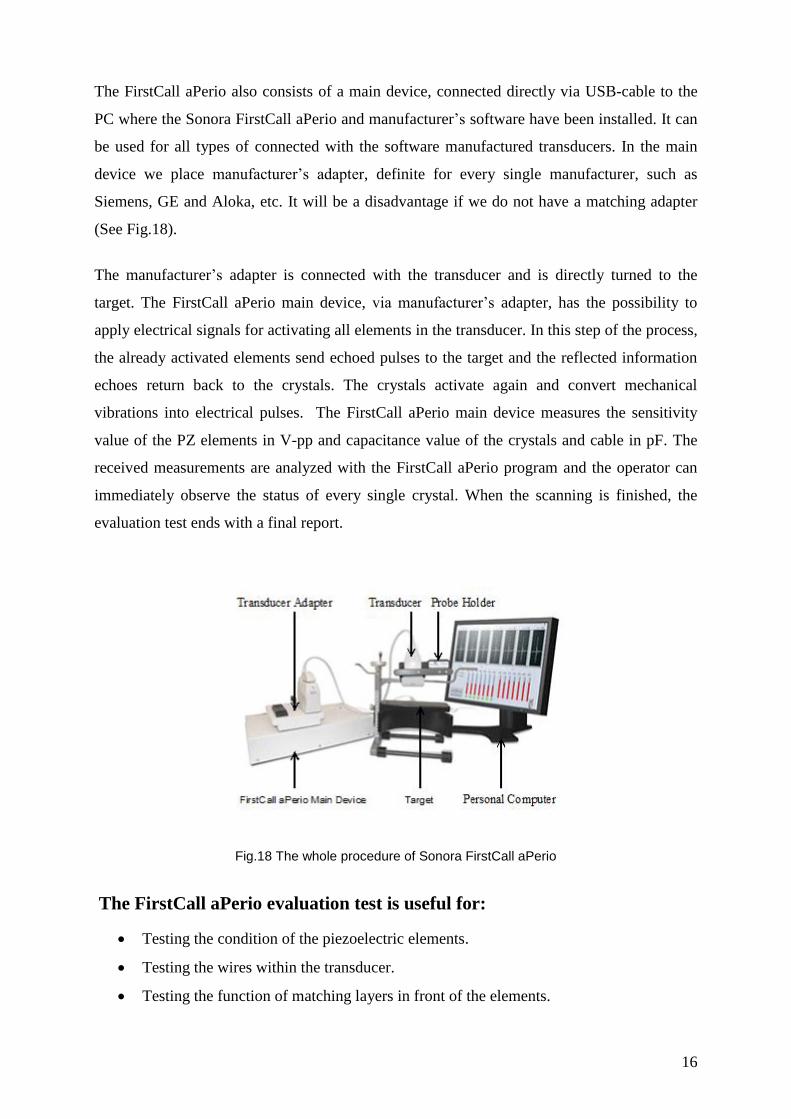
The FirstCall aPerio also consists of a main device, connected directly via USB-cable to the
PC where the Sonora FirstCall aPerio and manufacturer’s software have been installed. It can
be used for all types of connected with the software manufactured transducers. In the main
device we place manufacturer’s adapter, definite for every single manufacturer, such as
Siemens, GE and Aloka, etc. It will be a disadvantage if we do not have a matching adapter
(See Fig.18).
The manufacturer’s adapter is connected with the transducer and is directly turned to the
target. The FirstCall aPerio main device, via manufacturer’s adapter, has the possibility to
apply electrical signals for activating all elements in the transducer. In this step of the process,
the already activated elements send echoed pulses to the target and the reflected information
echoes return back to the crystals. The crystals activate again and convert mechanical
vibrations into electrical pulses. The FirstCall aPerio main device measures the sensitivity
value of the PZ elements in V-pp and capacitance value of the crystals and cable in pF. The
received measurements are analyzed with the FirstCall aPerio program and the operator can
immediately observe the status of every single crystal. When the scanning is finished, the
evaluation test ends with a final report.
Fig.18 The whole procedure of Sonora FirstCall aPerio
The FirstCall aPerio evaluation test is useful for:
Testing the condition of the piezoelectric elements.
Testing the wires within the transducer.
Testing the function of matching layers in front of the elements.

17
Testing the backing material behind the elements.
2.1 Acceptance criteria according to FirstCall aPerio Operator’s Manual
Number of contiguous or non-contiguous weak or dead elements not allowed:
More than 4 non-contiguous weak elements.
Equal to 2 contiguous weak elements.
More than 1 dead element (Moore, 2006).
Accepted criteria by FirstCall aPerio concern all tested probes and it does not matter if the
transducer is in warranty or not. During the project work one of the established criteria was
modified: no more than 2 non-contiguous elements classified as "weak elements" instead of
no more than 4 non-contiguous weak elements. This new criterion is only in regard to probes
in warranty. From an economical point of view, the purpose was to limit, as much as possible,
the number of fault elements and avoid the use of defective transducers influencing both the
image and diagnosis quality. During operation, probably, these weak elements will become
dead, the probe should be replaced with a new one, which leads to financial losses for the
hospital.
2.2 How to determine if a probe is allowed to be repaired, according
to the recommendations by FirstCall aPerio operator’s manual
Any array with no more than 4 consecutive weak elements and no more than 2 non-
consecutive dead elements, otherwise these elements are evaluated in the context of a lens
delamination; i.e. if the lens is delaminated elements may look as weak or dead while in fact
they are not (Moore, 2006).
2.2.1 Effects of long cables in Ultrasonic
Cable attenuation: The resistance in long cables provides a disadvantage, causing loss
of signal, which increases with the length of the cable.
Cable noise pickup: it can catch RF noise from the environment and this affects the
quality of many applications.
Cable reflection: the excitation pulse transmits from the ultrasound system to the
transducer move speed of light. When the pulse arrives to the transducer, a big part of

18
electrical energy converts into sound waves. Part of this energy is reflected back to the
ultrasound system, and part of it is reflected back to the transducer.
Cable delay: the wires of the transducer cable are a part of total distance and thickness
measurement. When they are too long the pulses times become longer, which activates
the elements. It affects the examination processes.
2.3 FirstCall aPerio evaluation report
The most important parts of the evaluation report are to observe the sensitivity and
capacitance. They are observed by the operator or medical engineer.
2.3.1 Sensitivity
Sensitivity measures the functional status of every single PE crystal within the transducer
array. There should be only minor variations among the amplitudes of the signals for the
individual crystals in an array. The sensitivity is shown as a graph: the X-axis shows the
numbers of the PZ elements. The Y-axis shows the sensitivity as response of the PZ elements
within the probe, which measures peak to peak amplitude (the change between highest
amplitude value and lowest amplitude value) of the reflected pulses in voltage (V) (See Fig.19
and 20).
The 3 differently coloured thresholds (red, yellow and green) determine the functional state of
crystals in a transducer. In contrast with the 3 differently coloured columns (red, yellow and
green), which represent the three different zones of probe, they determine the criteria of the
transducer evaluated test. The red zone is the most important because it covers the central part
of a transducer, respectively the image, and then follows the two yellow zones that border
both sides of the red. The two-side parts of the transducer are occupied by two green zones,
they are less important than the others; because green zones cover the peripheral parts of an
image (See Fig.19 and 20).
According to its functional status, every element can be good, week or dead. In order to be
defined as good, the sensitivity of the element should be equal to or over 75% of the mean
value of all separate elements. On the bar graph this level is shown in green colour threshold
that defines the initial border of acceptable functional status of the elements.

19
As weak elements are classified those ones, whose sensitivities vary within the range of
10% - 75% of the mean values of all separate crystals: all elements which are situated
between red and green colour threshold are evaluated as week. Sensitivity level equal to or
less than 10% of the mean value of all separate elements is an indicator for a dead element,
short circuit, break in cable, opening in the pin connector or lens delamination, which is
determined later by capacitance value bar graph. On the sensitivity graph, the level which
limits the non-functional elements from the other is shown in red colour threshold (Moore,
2006).
Fig.19 Sensitivity of PE elements within the transducer phased array 10 MHz. It was determined as a good working transducer because there were 3 non-consecutive week elements (2 in the red zone and one in the green zone), and no dead elements that respond to the FirstCall operator’s manual references.
Fig.20 Sensitivity of PE elements within the transducer phased array 10MHz. This probe was classified as defective because there were much more than the accepted weak and dead elements and they were evaluated as lens delamination, according to the FirstCall operator’s manual references.

20
2.3.2 Capacitance
Capacitance is the measure of the electrical performance of each individual element circuit.
The acoustic array naturally works as a capacitor. For instance: Linear array of high
frequency, such as 7.5 MHz and above are usually smaller arrays and have a lower
capacitance nearly 50 pF. Lower frequency transducer as curved array 3.5 MHz has larger
elements and higher capacitance nearly 350 pF. The cable itself also has capacitance.
The new ultrasound apparatus probe cables have been designed to have low capacitance,
approximately equal to 85pF. But the old probe cables have higher capacitance, equal to
120pF.
The capacitance is shown as a bar graph, which translates the received information from
sensitivity graph. It exactly determines the type of defect in the elements. The numbers of PZ
crystals are situated on the X-axis, and the Y-axis shows the capacitance measured in pF.
Foremost the mean value of capacitance in pF should be defined, for all elements, and then
the maximum and minimum capacitance thresholds (shown in the bar graph with blue colour)
should be determined. The maximum threshold was assigned +10% of mean value
capacitance. The minimum threshold was defined -10% of mean value capacitance (See
Fig.21 and Fig.22). The capacitance values of good working elements appeared on and within
the maximum and minimum capacitance thresholds. If the capacitance test of an element
appears under the minimum threshold and approximately to the mid-point of the mean value
capacitance scale, the element is dead. When the capacitance is close or equal to zero a wire
could be opened in the connector or there might be a break in the cable. If the capacitance is
higher than maximum threshold and mean capacitance value of the other elements, it indicates
a short somewhere in the circuit (Moore, 2006).
Fig.21 Capacitance of PE elements within the transducer phased array 10MHz. It was determined as a good working transducer because the capacitance values of all elements appeared on and within the maximum and minimum capacitance thresholds that respond to the FirstCall operator’s manual references.

21
Fig.22 Capacitance of PE elements within the transducer phased array 10MHz. This probe was classified as defective with dead elements, because the capacitance values of many elements appeared under the minimum capacitance threshold, according to the FirstCall operator’s manual references.
It is visible in the FirstCall aPerio operator’s manual that the Y-axis scale on sensitivity and
capacitance bar graphs has variable values, depending on the mean value of all separate
elements in a certain probe, i.e. the mean value varies depending on the number of elements
and their certain sensitivity (V-pp) or capacitance (pF) values.
Mårtensson suggested that the returning pulse could be measured by pulse width, pulse
waveform, bandwidth, peak-to-peak amplitude and centre frequency. To avoid breaks in the
cable and short circuits, it is necessary to control the capacitance of every single element and
the wires within the transducer cable. The transmitting and receiving of US pulses can be
measured with peak to peak amplitude sensitivity (Mårtensson, 2011).

22

23
3. Results
3.1 Review of the results after the evaluation test
For the thesis project, a total of 73 transducers were tested produced by 3 different
manufactures: Siemens, GE healthcare and Aloka.
After the evaluation test using FirstCall aPerio Testing Accreditation Program and
manufacturers recommendations, 61 transducers have passed and 12 have failed; 6 of 12 had
dead elements as a common reason for not passing. The following defects were also observed:
from 73 transducers, 33 elements were dead, 38 had breaks in the cables, 6 had short circuits
and 26 elements were weak in the red zone. In the green zone, 12 crystals were dead, 1 had a
break in the cables, no short circuits were found and 4 elements were weak. The yellow zone
was represented by 19 dead elements, a break in cable, no short circuit crystals were found
and there were 3 weak elements.
Delamination appeared in two probes, one of them had the dead elements of the 3 different
zones and the other one had the dead elements of the red zone.
The analysis showed that most of the defective crystals were situated in the red zone. This
zone is the middle part of the transducer and, due to that, any failure there has much bigger
influence over the quality of the image than the problems in the other two zones (See Table
2).
Table 2 Red, green and yellow zone error distribution for FirstCall aPerio
Classified by manufacturer, I had 32 transducers from the whole quantity of 73. Their
equipment, however, had some common defects. In linear array, there was 1 broken
transducer. In curved array, there were 3, and in phased array 6 non-functioning transducers.
Manufacturer II had 9 transducers and only one phased array transducer showed a defect.
Manufacturer No: of
probes Red zone elements Green zone elements Yellow zone elements
Dead Broken Short Weak Dead Broken Short Weak Dead Broken Short Weak
I 32 14 3 6 14 12 0 0 4 19 1 0 2
II 9 14 0 0 9 0 0 0 0 0 0 0 1
III 32 5 35 0 3 0 1 0 0 0 0 0 0
Total 73 33 38 6 26 12 1 0 4 19 1 0 3

24
Manufacturer III had 32 transducers; one curved array did not pass the evaluation test (See
Table 3).
Table 3 Transducer Evaluation Test Result for linear, curved and phased array
The higher level of error in transducers appeared in Radiology Department. The reason for the
highest quantity of fault transducer can be the aging of US equipment, intensive exploitation
or a staff working incorrectly with the system (See Table 4).
Table 4 Transducer Evaluation Test Result (bad working probes for different departments)
Table 5 Transducer Evaluation Test Result
Manufacturer Total
Trans.
Number of
Failed
Linear
Array
Number
of Failed
Curved
Array
Number of
Failed
Phased
Array
Total
error %
Linear
Array
Total
error %
Curved
Array
Total
error %
Phased
Array
I 32 1 3 6 2,77 8,33 16,66
II 9 0 0 1 0 0 6,25
III 32 0 1 0 0 2,94 0
Total 73 1 4 7 1,16 4,65 8,13
Manufacturer Total
Trans.
Radiology Physiology Gynaecology Childbirth Cardiology
I 32 8 0 0 0 2
II 9 0 0 0 1 0
III 32 0 0 0 0 1
Total 73 8 0 0 1 3
Manufacturer Total Trans. Pass Fail Manufacturer
Error
(%)
Total Error
(%)
I 32 22 10 31,25 13,69
II 9 8 1 11,11 1,36
II 32 31 1 3,125 1,16
Total 73 61 12 16,44 16,44

25
The regular evaluation test using FirstCall aPerio of all newly acquired and available
transducers gives an actual and precise review of the functional status of US equipment. In
this way, the quality of diagnosis and patient’s safety is increased, which is the main focus of
this thesis. Out of the financial part, it has become clear that nearly half of the defect US
transducers were in warranty and were replaced with new ones. Thus, the newly acquired
transducers which have shown defects were immediately replaced.
3.2 Images from probes that passed and did not pass the evaluation
test
Fig.23a The image was taken by transducer phased array 10 MHz. The received image is clear, which indicates a good quality of the probe.
Fig.23b Sensitivity of PE elements within the transducer phased array 10 MHz. It was determined as a good working transducer because there were 3 non-consecutive week elements (2 in the red zone and one in the green zone), and no dead elements that respond to the FirstCall operator’s manual references.

26
Fig.23c Capacitance of PE elements within the transducer phased array 10MHz. It was determined as a good working transducer because the capacitance values of all elements appeared on and within the maximum and minimum capacitance thresholds, that respond to the FirstCall operator’s manual references.
Fig.24a The image was taken by transducer phased array 10 MHz. The received image exhibited some
black areas, resulting from the defective probe.
Fig.24b Sensitivity of PE elements within the transducer phased array 10MHz. This probe was classified as defective because there were much more than the accepted weak and dead elements and they were evaluated as lens delamination, according to the FirstCall operator’s manual references.

27
Fig.24c Capacitance of PE elements within the transducer phased array 10MHz. This probe was classified as defective with dead elements, because the capacitance values of many elements appeared under the minimum capacitance threshold, according to the FirstCall operator’s manual references.
3.3 Common US probe failures discovered during the project
During the inspection, the transducer probes showed the following common failures:
Cracks on the handle.
Destroyed lens material.
Swelling of the lens material.
Damaged pins in the probe connector.
Using a ’pin-less’ connector, for example Siemens/Acuson sequoia probes, ensures
that the surface of the connector is clean.
Lens problems:
Dislocation of the lens from housing.
Hole in lens (See Fig.26).
Swollen lens.
Scratches on the lens
Various structural defects:
Destroyed structure of the pins in the connector.
Bad contact, dirty pin-less connector.
Broken lens cap.
Cable problems:
Scratches in the cables (See Fig.28).

28
Cable which is run over by the wheels of the US equipment (See Fig. 27).
TEE Re-coat and Re-Label:
The most common problem of TEE probe is to re-coat and re-label the depth markers.
They can disappear during sterilization procedure.
What can damage a transducer?
Perfume gels or other molecular changing substances.
Discharging of electric signals on or around the lens of the transducer or on the probe
connectors.
Dropping the transducer, or some other force damage (See Fig.25)
Incorrect handling during cleaning and sterilization process.
Bad storage environment.
Not ensuring that the image has frozen before connecting to or removing the
transducers out of the system.
Fig.25 Broken case of probe Fig.26 Holes in the lens
Fig.27 Cable runs over Fig.28 Scratches in the cable

29
4. Discussion
4.1 Overview of master thesis goals and results considerations
The master thesis project started with two basic purposes. The first one was to test all of the
available and newly acquired transducers in four hospitals in Gävleborg area. According to
this aim, there were 73 transducers were tested by the FirstCall aPerio system 61 of them
passed the evaluation test, and 12 did not pass. The probes were produced by 3
manufacturers: GE Health Care, Siemens and Aloka. Unfortunately during the performance a
limitation was met because of the absence of suitable adapters for all of different
manufactures and models of probes. Some probes have missed the evaluation test. It is a long
period perspective to provide as many as possible adapters for the different types of probes
and manufactures.
The second aim of the master study was to find out the advantages and disadvantages of
FirstCall aPerio evaluation test. The most important of them are presented below as follow:
Advantages
It is easy and flexible for testing.
During the evaluation test, it is immediately visible, through the report, in which
element the defect is.
It can precisely distinguish the source of error: weak, dead element, short circuit and
break or open connector in the wire.
It helps to early discover the error, and repair the transducer.
By reducing the transducer faults, the risk of wrong diagnosis is also minimized.
Database collections save all measurements data.
It is possible to test the transducer without US equipment.
Disadvantages
No acceptance criteria for transducer’s evaluation test, according to zone distribution
of the defective elements and according to the different types of probes.
Not enough adapters for all types of transducers.
Bubbles sometimes affect the evaluation test of the transducer.

30
Environmental factors and noise can badly affect the diagnostic test.
Some of the units of the FirstCall aPerio are made of metal and when regularly in
connect with water they can get rust which changes the chemical structure of the water
and can, respectively, influence the final test result.
Sometimes, in controlling the alignment transducer application window, it is difficult
to reach the absolute zero level of depth to get the optimal distance between the
transducer and a target.
From the presented above advantages and disadvantages, it can be concluded that FirstCall
aPerio evaluation test is a suitable testing system, which allows controlling the functional
status of a transducer and can distinguish the source of error. According to the accepted
criteria, the operator can determine if the probe can be repaired on time, thus avoiding its
influence on the quality of image. Parallel with the advantages of the testing device, there
were outlined some disadvantages were outlined as described above. At the time of the
project preparing, on the medical market of Sweden, there was no other evaluation testing
system for transducers, so the used testing device of FirstCall aPerio gave possibility for a
basic overview on the functional status of US probes. Nowadays, some of the new generation
US equipment has a self-control function for testing of the transducer. Together with a
suitable evaluation test, it is a big advantage to compare and consolidate the test results.
Usage of defective transducers appears as a common reason for misdiagnosis. Such cases are
described by Mårtensson in his Ph.D study High incidence of defective US transducers in use
in routine clinical practice, 2011. Some of the reports concern missed congenital heart
disease and incorrect diagnosis of miscarriages.
The process of evaluation test consists of two main parts. Generally, the first one is the
functional control of the elements within the probe. This part is a basis for the further process
of evaluation because it clarifies what is the condition of the crystals. When there is a clear
view of the number of weak and dead elements or if there are any other defects, the operator
should decide whether the probe has passed the test, can be repaired or it should be replaced,
in compliance with the second part of the evaluation test. Nowadays, one of the fundamental
problems is that there are no constant and well built acceptance criteria for evaluation of
transducers. These ones established by FirstCall aPerio, concern all tested probes, however,
they do not distinguish the different types of transducers and cannot make clear if the probe is
still in warranty or not. As Mårtensson has observed during his project work, which was also

31
noticed during the time of master thesis performance, according to the activation pathway,
every of the three types of transducers had a different predisposition to various defects. Just
one dead element in linear array can influence the image quality but more than one dead
element in the phased array could hardly be distinguished only from the received image.
During the project work, the acceptance criteria of the FirstCall aPerio evaluation test for
transducers turned to be important. One of the established criteria was modified: no more than
2 non-contiguous elements classified as "weak elements" instead of no more than 4 non-
contiguous weak elements. This new criterion covered all types of probes in warranty. From
an economical point of view, the purpose was to limit, as much as possible, the number of
fault elements and avoid use of transducers which might influence both the image and
diagnosis quality. During operation, probably, these weak elements will become dead, the
probe should be replaced with a new one, which leads to financial losses for the hospital. It
was already marked that the accepted criteria of FirstCall aPerio operator’s manual were
similar for every type of transducers. As it is known, however, the number and situation (red,
yellow and green zone) of defect crystals have different influence on the image, for the
various types of probes. The fault elements in the probe red zone have higher influence over
the image quality than the elements defects in the other two zones. If the situation of the
eligible weak and dead elements, when the acceptance criteria were created, was specified, it
would be much better. In this case, the final assessment would depend on the operator and on
the individual transducer, leading to many variations from operator to operator and from
hospital to hospital. During the project work, the minimizing of defect elements in the red
zone of all types of probes was a priority. Sometimes, more weak elements are permitted than
the determined ones in the operator’s manual acceptance criteria, if the fault elements are
situated in the green zone (in the peripheral parts of an image), however, only if it is not a risk
for misdiagnosis. The functional status of such transducers should be observed more often
than usual.
As a future plan, it was established to more precisely observe the connection between every
single type of probe and the number and situation of errors influencing the image quality.
According to this purpose, additional changes of the acceptance criteria of transducer’s
evaluation should be expected.
The observations on common US transducers defects, drawn under the period of thesis work
were: as it was mentioned above, 12 transducers were determined as defective, the dead

32
elements among the tested probes had the highest error rate, of course, according to the types
of transducers, the highest defect level was observed in the phased arrays. The most defective
probes were found in the radiology department. Delamination appeared in two of the tested
probes, during the master project work, as one of them had the dead elements within the 3
different zones, and the other one had the dead elements within the red zone, one probe
showed electrical fault as high leakage currant. According to the influence of different types
of defects over patient’s safety, short circuit and break in cable, causing high leakage current
or voltage, appear as higher risk agents than the elements classified as non-operating items.
Electrical fault as high voltage or/and high leakage current, however, affects not only the
quality of an image but can have a lethal impact. Basically, dead elements and especially
delamination affect the quality of the image and increase the possibility of false diagnosis and
treatment.
Some speculations could be emphasized in regard to the reason of fault, number of defective
transducers and the departments they belong to. Basically, the reasons can be categorized as
follow: aging of US equipment, intensive exploitation (longer period of using of the US
transducers decrease the functional lifetime of probes), a staff working incorrectly with the
system or incorrect transportation and storage of the US equipment (scratching the cables and
transducer’s lenses, break in the cable and hitting the probe) or handling system. One of the
observations made under the period of probe testing was that in some departments, for
instance, radiology department, the transducers were constantly connected and disconnected
from the US equipment. Probably, it could be the common reason for the highest rate of
defective probes in the mentioned department. Also, it should be mentioned that the
transducer’s functional status was tested for the first time, which means that some of the fault
probes could be repaired on time, before the appearance of delamination or would be
replaced.
The exact reason for appearing of defect is still unclear: sometimes, it can be a complex of
more than one reason. US equipment is a sensitive and expensive medical device. It is
extremely important to determine in which cases the defective probe should be replaced and
when it can be marked to be followed but still in operation. Foremost, the patient’s safety
should be guaranteed.

33
4.2 Patient Safety
Patient’s safety is a very important part of the health care system. It can be achieved by
avoiding the incorrect diagnosis and treatment and minimizing the recovery time.
According to the influence of different types of defects over patient’s safety, short circuit and
break in cable, causing high leakage current or voltage, appear as higher risk agents than
elements classified as non-operating items. Basically dead elements affect the quality of
image. Electrical fault as high voltage or/and high leakage current, however, it affects not
only the quality of an image but can have a lethal impact.
4.2.1 Patient’s safety problems caused by unsafe medical care
Medical drug treatment and device errors.
• Errors during surgery and respectively anesthesia.
• Infections.
• Blood products, which are not under control.
• Incomplete health care for children, pregnant women, newborns and elderly people.
Misdiagnosis, error in diagnosis and errors in interpreting test results for instance:
images.
Non-qualified staff.
Communication errors, for instance: language problem and lack of discussion with the
patient about future plans and variants of treatment.
Technical problems, including old or broken apparatus.
Leakage of the current test.
4.3 Requirements regarding design and manufacture
1. The properties of chemical, physical and biological characteristics.
2. Infection and microbial pollution.
3. Environmental characteristics of manufacturing.
4. Precise measuring of the devices functioning.
5. Protection against radiation.
6. Information and technical report supplied by the manufacturer.

34
4.4 Reducing of risk factors
It can be provide by:
1. The risk level can be reduced by optimization of the design, protection measure and by
providing the users with information.
2. Performance verification procedure: approximately on every 6 months.
3. Following the safety instruction during operation.
4. Correct storage and transport.
5. Correct usage of US equipment or transducer.
6. Avoiding of design or manufacturing defects, for instance: sometimes, the evaluation
test of a new transducer encounters a process of delamination which means defect in the
lens material.
7. High qualification of the staff.
8. Limitation of deficiencies in maintenance.
The following can be included in risk analysis: Transducer, different components, equipment,
operation systems and projects. In risk analysis, it is important to use questions, such as:
What can go wrong?
How likely is it?
What are the consequences?
Is it acceptable?
Acceptable risks: these are risks in determining parameters, which do not influence the quality
of the image and diagnosis. The most important thing is to ensure that the negative side effect
must never overweigh the positive. This is an obligatory requirement of the directives and
allows marking the product by CE sign.
Nowadays, the medical market in Sweden offers only one transducer test device, FirstCall
aPerio, which limits the possibility to compare the received results of the evaluation test with
another probe test device. Fortunately, some of the medical manufacturers introduced a new
US system which includes self-control for the functional status of the transducers. It provides
a big advantage because in combination with the evaluation test device it will confirm the test
measurements.

35
5. Conclusions
This study has two aims: The first one has orientated into early discovering of defect in
acquired new transducers and available probes. It is often observed that there are some
manufacturing defects, which can hardly be discovered immediately without any test control.
The problem with such kind of failures is that they remain hidden during operation, which
reflects over the image quality and the quality of diagnosis. During the project there was
detected such probe thanks to the evaluation test and they were replaced immediately.
Unfortunately, some difficulties appeared in the initial phase of the project, because of the
absence of adapters to some models of US probes. Because of that, those transducers are still
in operation, skipping the evaluation test. This may cause some risk for inaccurate medical
diagnosis.
Future perspective is based on periodical observation of physical and functional status of
existing US transducers at the mentioned above hospitals. The basic purpose is to increase the
quality of health care.
Second aim is to find out the advantages and disadvantages of The FirstCall aPerio evaluation
test. The test was developed to reduce the risk level of wrong diagnosis and to ensure optimal
results by regular test of physical properties of the US transducer. With this device it is easy
to classify and document the key indicators of potential areas of transducer problems, for
instance: weak or dead elements, short circuit or break in the cables. It gives a possibility to
compare the final result of the images and a received report, which are based on well working
or bad working probes.
Collecting of statistical data and analysis are the next points of interest, corresponding to the
second goal of this study. It is extremely important to have a clear technical overview on the
status of available US equipment and transducers; to keep under control every probe marked
for observation; to see the common defects in the probes. For the leading hospitals, it is
necessary to invest time and money to improve the professional level of medical staff. The
basic purpose of the medical health care is to keep high level of patient’s safety and to
minimize the possibility of errors. This could be ensured not only by the equipment but also
by the staff’s skills to work with it. For this reason, lots of trainings were organized about the
correct use of US systems. According to the received results, this basic purpose can be
classified as fulfilled.

36
Based on the study made, the following conclusions were drawn: a functional test of the
elements of US transducer gives a clear clinical picture and at any time, it is known in what
condition the available probes are. Those ones which did not pass the test (amongst the
acquired new probes and transducers in warranty) were immediately replaced with new
devices. The financial advantages for the hospital were significant.
During the test period, the functions of transducers were observed. Devices have been
belonging to different departments of 4 hospitals in Gävleborg area. The total number of
tested transducers was 73. They were produced by 3 different manufactures: Siemens, GE
health care and Aloka. 12 of them did not pass the evaluation test. Only 1 transducer showed
a high leakage current fault under the evaluation test. To avoid a future wrong diagnosis, all
of the transducers which were detected with some errors, were immediately replaced with
new ones.

37
6. Acknowledgements
First and foremost I would like to thank my supervisor Björn Wändel, who has given me the
possibility to realize and enjoy this project. He is the person who helped me to express and
develop my interest and knowledge in the sphere of Medical imaging.
This project could not exist if it wasn’t for my family. Thank you for the support and for the
inspiration. To my mum and Silvia, my wife: Without you I could not reach my dreams. Sara,
please forgive me that I did not have so much time as I would like to have to play with you,
my little princess.
Special thanks to Prof. Birgitta Janerot and Frida Lindberg as well, who guided me in writing
this thesis report.
I would also like to thank Lennart Zetterberg and Anders Blix, who have helped me and
introduced me to so many things in the time we spent together working on this project.
Thanks to all colleagues from Biomedical Engineering Department in Gävle Hospital, the
time I spend with you gives me a lot of positive energy.

38

39
7. References
1. Asher, R.C, Ultrasonic Sensors, ISBN: 978-0-750-30361-3, 1997, 2:14, 2:31, 4:73.
2. Bertolotto, M., Derchi, L. et al. Color Doppler US of the Penis, ISBN: 978-3-540-
36676-8, 2008, 1:4.
3. Chatterjee, S.; Miller, A., Biomedical instrumentation systems,
ISBN: 978-4180-1866-5, 2009, 14:433.
4. Galiuto, L., Garbi, M. et al. The EAE textbook of Echocardiography, ISBN: 978-0-19-
959963-9, 2011, 1:2.
5. Gibbs, V., Cole, D. et al. Ultrasound physics and technology, ISBN: 978-0-7020-
3041-3, 2009, 5:27.
6. Gibson, I., Feng, W. et al. Advanced Manufacturing Technology for Medical
Application, ISBN: 0-470-01688-4, 2005, 4:64.
7. Goldberger, J., Edward, J. et al. Practical Signal and image processing in clinical
cardiology, ISBN: 978-1-84882-514-7, 2010, part II 14:189.
8. Hofer, M., Ultrasound Teaching Manuel The basic of performing and interpreting
ultrasound scans, ISBN: 1-58890-279-X, 2005, 1:9.
9. Machi, J., Ultrasound for surgeons, ISBN: 0-7817-4291-9, 2005, 3:26.
10. Martin, K., Ramnarine, K. et al. Diagnostic Ultrasound physics and equipment, ISBN:
978-0-521-75710-2, 2010, 2:13.
11. Maulik, D., Doppler ultrasound in obstetrics and gynecology, IBSN: 10 3-540-23088-
2, 2005, 8:101.
12. Moore, G.W., FirstCall aPerio operator’s manual, Sonora Medical System, Longmont-
USA, 2006, 8-23.
13. Mårtensson, M., Evaluation of errors and limitations in ultrasound imaging systems,
doctoral thesis, ISBN: 978-91-7501-026-7, 2011, 4:24, 6:45-46.
14. Mårtensson, M., Olsson, M. et al. “High incidence of defective ultrasound transducers
in use in routine clinical practice”, European Journal of Echocardiography, 2009, 389-
394.
15. Mårtensson, M., Olsson, M. et al. “Ultrasound transducer function: annual testing is
not sufficient”, European Journal of Echocardiography, 2010, 801-805.
16. Narouze,S.N., Chan, V. et al. Atlas of ultrasound guided procedures in interventional
pain management, ISBN:978-14419-1679-2, 2010, part I 2:14

40
17. Ostensen, H., Basic physics of ultrasonographic imaging, ISBN: 92-4-159299-0, 2005,
3:25.
18. Pye, S.D., Ellis, W. et al. “Medical ultrasound: a new metric of performance for grey
scale imaging”, Journal of Physics, 2004, 188.
19. Sanders, R., Del Prince, B. et al. Clinical Sonography, a practical guide, ISBN: 0-
7817-4869-0, 2007, 2:14.
20. Walker, A., Performance Testing of Ultrasound Doppler Equipment, ISBN: 978-91-
7393-498-5, 2003, 1:12.
21. Zagzebski, J.A., Essentials of ultrasound physics, by Mosby in St. Louis,
ISBN: 978-08-1519-852-9, 1996, 2:22, 2:31, 5:88-89, 5:93-96.