ultrasonic transcutaneous energy transfer using a ...shmilo/23.pdf · ultrasonic transcutaneous...
TRANSCRIPT
Ultrasonics 50 (2010) 666–674
Contents lists available at ScienceDirect
Ultrasonics
journal homepage: www.elsevier .com/ locate/ul t ras
Ultrasonic transcutaneous energy transfer using a continuous wave 650 kHzGaussian shaded transmitter
Shaul Ozeri a, Doron Shmilovitz a,*, Sigmond Singer a, Chua-Chin Wang b
a School of Electrical Engineering, Tel-Aviv University, Israelb Dept. of Electrical Engineering, National Sun Yat-Sen University, Taiwan
a r t i c l e i n f o
Article history:Received 9 December 2009Received in revised form 13 January 2010Accepted 13 January 2010Available online 6 February 2010
Keyword:Ultrasonic transcutaneous energy transfer
0041-624X/$ - see front matter � 2010 Elsevier B.V.doi:10.1016/j.ultras.2010.01.004
* Corresponding author.E-mail address: [email protected] (D. Shmilovit
a b s t r a c t
This paper proposes ultrasonic transcutaneous energy transfer (UTET) based on a kerfless transmitterwith Gaussian radial distribution of its radiating surface velocity. UTET presents an attractive alternativeto electromagnetic TET, where a low power transfer density of less than 94 mW/cm2 is sufficient. TheUTET is operated with a continuous wave at 650 kHz and is intended to power devices implanted upto 50 mm deep. The transmitter was fabricated using a 15 mm diameter disc shape PZT (Lead ZirconateTitanate) element (C-2 grade, Fujiceramics Corporation Tokyo Japan), in which one surface electrode waspartitioned into six equal area electrodes (�23 mm2 each) in the shape of six concentric elements. TheUTET was experimented using pig muscle tissue, and showed a peak power transfer efficiency of 39.1%at a power level of 100 mW. An efficient (91.8%) power driver for the excitation of the transmitter array,and an efficient rectifier (89%) for the implanted transducer are suggested.
To obtain the pressure field shape, the Rayleigh integral has been solved numerically and the resultswere compared to finite element simulation results. Pressure and power transfer measurements withina test tank further confirm the effectiveness of the proposed UTET.
� 2010 Elsevier B.V. All rights reserved.
1. Introduction
Transcutaneous energy transfer (TET) is a technique used to re-motely power implanted devices. Presently existing TET devicesimplement electromagnetic power coupling between externaland implanted coils featuring power transfer of up to 10 W [1–4]. For transferring power with power density of up to 94 mW/cm2, an ultrasonic transcutaneous energy transfer (UTET) basedon transmitting ultrasonic waves can be used [5,6]. Using ultra-sonic waves rather than electromagnetic waves has the benefit ofbeing less susceptible to nearby ferromagnetic materials, in addi-tion to exhibiting high power transfer efficiency (27%) [6]. Astraightforward realization of a UTET is presented by [6], using aflat circular piezoelectric ultrasonic transmitter feeding an im-planted piezoelectric receiver by the acoustic waves of 673 kHz.In such a realization of UTET, the transmitting element is electri-cally excited to impose a uniform electrical excitation, which inturn generates a uniform surface vibration velocity amplitudeand phase over the radiating surface. The uniform transmitter’ssurface vibration has the advantage of having self natural focusingzone [8], and being simple to realize. However, beyond the selffocusing zone, the intensity rapidly decreases at a rate proportionalto 1/R2 (R stands for the distance from the radiating surface). That
All rights reserved.
z).
implies that a finite aperture size receiver (of approximately threewavelengths) can capture only part of the power transmitted. Fur-thermore, the beam profile contains alternate polarity side lobes[19] that reduce the available power at the receiver’s terminals.To overcome the spreading of the wave’s profile, ultrasonic devicessuch as imaging devices implement an apodization of the excita-tion waveform that forces a non-uniform radial distribution ofthe transmitter’s radiating surface. Durnin and Miceli [10] showed(for an optical signal) that excitation in the shape of zero order Bes-sel function of the 1st kind, J0 of an infinite aperture transducer, re-sults in an Axicon which is a non-diffracting propagating wave. Apractical implementation of the Bessel beam consists of a trans-ducer having a finite aperture size that proves also to be effective[9,11]. Unfortunately, for continuous power transfer through a liv-ing tissue, the Bessel beam has two disadvantages. It generates apressure field that consists of a main lobe concentrated along theacoustic axis, and several (<10 depends on the accuracy of the Bes-sel stepwise approximation) lower amplitude (�0.4, +0.3, �0.25,+� � �, normalized to the amplitude of the main lobe) side lobes [7]that travel in parallel with the main lobe [9,19]. Side lobes tendto decrease the amount of energy harvested by the receiver as ithas an alternating pressure polarity. The main lobe having a nar-row width (that depends on the aperture to wavelength ratio), con-centrates the wave’s energy within the narrow tissue’s crosssection, and consequently might increase the intensity of the wavebeyond the safety limit of 94 mW/cm2 [12,13].
θ
R
r
L(x,0,z).
z
x
y
a ψ
dS
Acoustical axisDirection of propagation
w σ
dσ
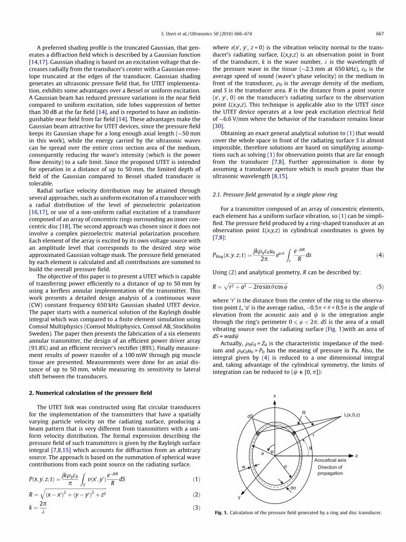
Fig. 1. Calculation of the pressure field generated by a ring and disc transducer.
S. Ozeri et al. / Ultrasonics 50 (2010) 666–674 667
A preferred shading profile is the truncated Gaussian, that gen-erates a diffraction field which is described by a Gaussian function[14,17]. Gaussian shading is based on an excitation voltage that de-creases radially from the transducer’s center with a Gaussian enve-lope truncated at the edges of the transducer. Gaussian shadinggenerates an ultrasonic pressure field that, for UTET implementa-tion, exhibits some advantages over a Bessel or uniform excitation.A Gaussian beam has reduced pressure variations in the near fieldcompared to uniform excitation, side lobes suppression of betterthan 30 dB at the far field [14], and is reported to have an indistin-guishable near field from far field [14]. These advantages make theGaussian beam attractive for UTET devices, since the pressure fieldkeeps its Gaussian shape for a long enough axial length (�50 mmin this work), while the energy carried by the ultrasonic wavescan be spread over the entire cross section area of the medium,consequently reducing the wave’s intensity (which is the powerflow density) to a safe limit. Since the proposed UTET is intendedfor operation in a distance of up to 50 mm, the limited depth offield of the Gaussian compared to Bessel shaded transducer istolerable.
Radial surface velocity distribution may be attained throughseveral approaches, such as uniform excitation of a transducer witha radial distribution of the level of piezoelectric polarization[16,17], or use of a non-uniform radial excitation of a transducercomposed of an array of concentric rings surrounding an inner con-centric disc [18]. The second approach was chosen since it does notinvolve a complex piezoelectric material polarization procedure.Each element of the array is excited by its own voltage source withan amplitude level that corresponds to the desired step wiseapproximated Gaussian voltage mask. The pressure field generatedby each element is calculated and all contributions are summed tobuild the overall pressure field.
The objective of this paper is to present a UTET which is capableof transferring power efficiently to a distance of up to 50 mm byusing a kerfless annular implementation of the transmitter. Thiswork presents a detailed design analysis of a continuous wave(CW) constant frequency 650 kHz Gaussian shaded UTET device.The paper starts with a numerical solution of the Rayleigh doubleintegral which was compared to a finite element simulation usingComsol Multiphysics (Comsol Multiphysics, Comsol AB, StockholmSweden). The paper then presents the fabrication of a six elementsannular transmitter, the design of an efficient power driver array(91.8%) and an efficient receiver’s rectifier (89%). Finally measure-ment results of power transfer of a 100 mW through pig muscletissue are presented. Measurements were done for an axial dis-tance of up to 50 mm, while measuring its sensitivity to lateralshift between the transducers.
2. Numerical calculation of the pressure field
The UTET link was constructed using flat circular transducersfor the implementation of the transmitters that have a spatiallyvarying particle velocity on the radiating surface, producing abeam pattern that is very different from transmitters with a uni-form velocity distribution. The formal expression describing thepressure field of such transmitters is given by the Rayleigh surfaceintegral [7,8,15] which accounts for diffraction from an arbitrarysource. The approach is based on the summation of spherical wavecontributions from each point source on the radiating surface.
Pðx; y; z; tÞ ¼ jkq0c0
p
ZS
vðx0; y0Þ e�jkR
RdS ð1Þ
R ¼ffiffiffiffiffiffiffiffiffiffiffiffiffiffiffiffiffiffiffiffiffiffiffiffiffiffiffiffiffiffiffiffiffiffiffiffiffiffiffiffiffiffiffiffiffiffiffiffiffiffiffiffiðx� x0Þ2 þ ðy� y0Þ2 þ z2
qð2Þ
k ¼ 2pk
ð3Þ
where v(x0, y0, z = 0) is the vibration velocity normal to the trans-ducer’s radiating surface, L(x,y,z) is an observation point in frontof the transducer, k is the wave number, k is the wavelength ofthe pressure wave in the tissue (�2.3 mm at 650 kHz), c0 is theaverage speed of sound (wave’s phase velocity) in the medium infront of the transducer, q0 is the average density of the medium,and S is the transducer area. R is the distance from a point source(x0, y0, 0) on the transducer’s radiating surface to the observationpoint L(x,y,z). This technique is applicable also to the UTET sincethe UTET device operates at a low peak excitation electrical fieldof �6.6 V/mm where the behavior of the transducer remains linear[30].
Obtaining an exact general analytical solution to (1) that wouldcover the whole space in front of the radiating surface S is almostimpossible, therefore solutions are based on simplifying assump-tions such as solving (1) for observation points that are far enoughfrom the transducer [7,8]. Further approximation is done byassuming a transducer aperture which is much greater than theultrasonic wavelength [8,15].
2.1. Pressure field generated by a single plane ring
For a transmitter composed of an array of concentric elements,each element has a uniform surface vibration, so (1) can be simpli-fied. The pressure field produced by a ring-shaped transducer at anobservation point L(x,y,z) in cylindrical coordinates is given by[7,8]:
PRingðx; y; z; tÞ ¼ jkq0c0u0
2pejxt
Zs
e�jkR
Rds ð4Þ
Using (2) and analytical geometry, R can be described by:
R ¼ffiffiffiffiffiffiffiffiffiffiffiffiffiffiffiffiffiffiffiffiffiffiffiffiffiffiffiffiffiffiffiffiffiffiffiffiffiffiffiffiffiffiffiffiffiffiffiffiffiffir2 þ a2 � 2rasinhcosw
pð5Þ
where ‘r’ is the distance from the center of the ring to the observa-tion point L, ‘a’ is the average radius, �0.5p < h < 0.5p is the angle ofelevation from the acoustic axis and w is the integration anglethrough the ring’s perimeter 0 6 w < 2p. dS is the area of a smallvibrating source over the radiating surface (Fig. 1)with an area ofdS = wadw
Actually, q0c0 = Z0 is the characteristic impedance of the med-ium and q0c0u0 = P0 has the meaning of pressure in Pa. Also, theintegral given by (4) is reduced to a one dimensional integraland, taking advantage of the cylindrical symmetry, the limits ofintegration can be reduced to (w e [0, p]):

668 S. Ozeri et al. / Ultrasonics 50 (2010) 666–674
PRing ¼2jkawP0ejxt
p
Z p
0
e�jkR
Rdw
¼ 2jkawP0ejxt
p
Z p
0
e�jkffiffiffiffiffiffiffiffiffiffiffiffiffiffiffiffiffiffiffiffiffiffiffiffiffiffiffiffiffiffir2þa2�2ra sinh coswp
ffiffiffiffiffiffiffiffiffiffiffiffiffiffiffiffiffiffiffiffiffiffiffiffiffiffiffiffiffiffiffiffiffiffiffiffiffiffiffiffiffiffiffiffiffiffiffiffiffir2 þ a2 � 2rasinhcosw
p dw ð6Þ
By defining:
A ¼ 2rasinhr2 þ a2 ð7Þ
The pressure expression becomes:
PRing ¼2jkawP0ejxt
pffiffiffiffiffiffiffiffiffiffiffiffiffiffiffir2 þ a2p
Z p
0
e�jkffiffiffiffiffiffiffiffiffir2þa2p ffiffiffiffiffiffiffiffiffiffiffiffiffiffi
1�A coswp
ffiffiffiffiffiffiffiffiffiffiffiffiffiffiffiffiffiffiffiffiffiffiffi1� Acosw
p dw ð8Þ
A similar approach gives the pressure generated by a disc shapetransducer:
PDiscðr; h; tÞ ¼jkP0
pejxt
Z p
0dwZ a
0r e�jkR
Rdr ð9Þ
A practical aperture size such as used in UTET is a = 7.5 mm andthe wave number is k � 2200 1/m. The pressure expression in (4) isvery oscillatory and therefore cannot have a closed analytical solu-tion. In addition, the technique known as stationary phase for thesolution of integrals in the form of I ¼
R p0 f ðwÞejb/ðwÞdw is applicable
only for the case of b ?1, but for the UTET b ¼ kffiffiffiffiffiffiffiffiffiffiffiffiffiffiffir2 þ a2p
¼ka
ffiffiffiffiffiffiffiffiffiffiffiffiffiffiffiffiffiffiffiffi1þ r2=a2
pwhich leads to 10 6 b 6 50. Since b is not sufficiently
large, the stationary phase technique is also not applicable. There-fore, to evaluate the pressure field without gross assumptions, anumerical solution is adopted.
2.2. Determining the pressure field due to contributions of all of thearray’s elements
Since the electrode area is partitioned into six concentric ele-ments with a narrow (�0.2 mm) clearance between adjacent ele-ments, apodization is achieved by connecting each element’selectrode to a separate excitation source. The excitation sourcesare designed to impose an excitation voltage according to a Gauss-ian mask. In practice, this is a gross stepwise approximation to theGaussian profile since the surface area of the transducer is dividedinto a small number (six in this work) of concentric elements. Alesser number of elements might lead to a ring width havingwidth–thickness ratio �1, which might cause undesired lateral
AcMaL
Thin coupling layer (Castor Oil ,
Ultrasonic Jell etc .)
P
Vg6 Vg5 Vg4 Vg3 Vg2 Vg1
5 –
UltrasonW
Annular Electrodes Pattern
15 mm diameterPZT Transducer
Skin Surface
Fig. 2. Illustration of the propo
vibrations [22]. The Gaussian excitation amplitude vðr�Þ profile cen-
tered at the center of the transducer is in the form of:
vð�rÞ ¼ e�a �rað Þ2 ð10Þ
where a is the transducer’s aperture, a is the Gaussian constant, and�r is the average concentric element’s radius.
Since the surface velocity is proportional to the excitation volt-age level, P0 is also proportional to vð�rÞ and the expression of thepressure field PL at observation point L(x,y,z) due to the contribu-tion of all rings is:
PRingðL; tÞ ¼2jkp
�XN
n¼1
anwnP0n
Z p
0
e�jkffiffiffiffiffiffiffiffiffiffiffiffiffiffiffiffiffiffiffiffiffiffiffiffiffiffiffiffiffiffiffiffir2þa2
n�2ran sin# coswp
ffiffiffiffiffiffiffiffiffiffiffiffiffiffiffiffiffiffiffiffiffiffiffiffiffiffiffiffiffiffiffiffiffiffiffiffiffiffiffiffiffiffiffiffiffiffiffiffiffiffiffir2 þ a2
n � 2ran sin#coswp dw
!ejxt
ð11Þ
This expression was solved numerically by replacing the inte-gration with a summation and its result has been added to thenumerical solution of (9) which is the expression representingthe contribution of the inner disc. N = 5 represents the number ofconcentric rings and n is the ring’s index of summation n � [1, N]
a : a1; . . . ; aN ð12Þ
fm;nðr; #;wm; anÞ ¼e�jk
ffiffiffiffiffiffiffiffiffiffiffiffiffiffiffiffiffiffiffiffiffiffiffiffiffiffiffiffiffiffiffiffiffiffir2þa2
n�2ran sin# coswm
pffiffiffiffiffiffiffiffiffiffiffiffiffiffiffiffiffiffiffiffiffiffiffiffiffiffiffiffiffiffiffiffiffiffiffiffiffiffiffiffiffiffiffiffiffiffiffiffiffiffiffiffiffiffir2 þ a2
n � 2ran sin#coswm
p ð13Þ
PLðr; #Þ ¼2jkpXN
n¼1
anwnP0n
XM
m¼1
fm;nðr; #;wm; anÞDw
!ð14Þ
Dw ¼ pM
ð15Þ
wm ¼ mDw; w : w1; . . . ;wM ð16Þh 2 ½�0:5p;0:5p� ð17Þ
3. Experimental set-up and results
The UTET link was constructed using flat circular transducersfor the implementation of the transmitter and the receiver. Theexcitation voltage was chosen to be a continuous wave with a fre-quency of 650 kHz, which is a frequency high enough to result in areceivers’ thickness of less than 5 mm (including matching layer),and low enough to have a reasonable average soft tissue attenua-
oustic tching
ayers
Rectifier89%
Efficiency
Load
Implanted Unit
15 mm diameterPZT Transducer
50mm
P
ic Traveling aves
~~
+-
sed Gaussian shaded UTET.
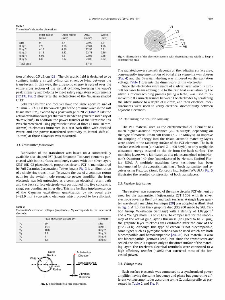
Table 1Transmitter’s electrodes dimensions.
Inner radius(mm)
Outer radius(mm)
Area(mm2)
Width(mm)
Disc 0 2.7 22.90 2.7Ring 1 2.9 3.96 22.84 1.06Ring 2 4.16 4.96 22.93 0.8Ring 3 5.16 5.82 22.78 0.66Ring 4 6.02 6.6 22.93 0.58Ring 5 6.8 7.32 23.06 0.52
Total area 137.44
V6V5
V4V3
V2V1
Fig. 4. Illustration of the electrode pattern with decreasing ring width to keep aconstant ring area.
S. Ozeri et al. / Ultrasonics 50 (2010) 666–674 669
tion of about 0.5 dB/cm [28]. The ultrasonic field is designed to beconfined inside a virtual cylindrical envelope lying between thetransducers. In this way, the ultrasonic energy is spread over theentire cross section of the virtual cylinder, lowering the wave’speak intensity and helping to meet safety regulatory requirements[12,13]. Fig. 2 illustrates the architecture of the Gaussian shadedUTET.
Both transmitter and receiver have the same aperture size of7.5 mm � 3.3k (k is the wavelength of the pressure wave in the softtissue medium), excited by a peak voltage of 20 V (Table 2 lists theactual excitation voltages that were needed to generate intensity of94 mW/cm2). In addition, the power transfer of the ultrasonic linkwas characterized using pig muscle tissue, at three (5 mm, 10 mm,40 mm) thicknesses immersed in a test bath filled with distilledwater, and the power transferred sensitivity to lateral shift (0–14 mm) at those distances was measured.
3.1. Transmitter fabrication
Fabrication of the transducer was based on a commerciallyavailable disc-shaped PZT (Lead Zirconate Titanate) elements pur-chased with both surfaces completely coated with thin silver layers(Z3T 15D-C2 piezoelectric properties close to PZT-4, manufacturedby Fuji Ceramics Corporation, Tokyo Japan). Fig. 3 is an illustrationof a single ring transmitter. To enable the use of a common returnpath for the switch-mode resonance power amplifier, the frontelectrode was left untouched as a common electrical return pathand the back surface electrode was partitioned into five concentricrings, surrounding an inner disc. This is a kerfless implementationof the Gaussian excitation’s quantization by six equal area(�22.9 mm2) concentric elements which proved to be sufficient.
Table 2Transmitter’s excitation voltages (amplitudes). V1 corresponds to the inner-mostelectrode.
Peak excitation voltage [V] Element
V1 20 DiscV2 14.4 Ring 1V3 10.8 Ring 2V4 7.2 Ring 3V5 4 Ring 4V6 1.6 Ring 5
Width
Inner Radius
OuterRadius
Polarization Direction
Acoustical Axis
Vibration Direction
Fig. 3. Illustration of a ring transmitter.
The radiated power strength depends on the radiating surface area,consequently implementation of equal area elements was chosen(Fig. 4) and the Gaussian shading was imposed on the excitationvoltage. Table 1 presents the dimensions of the electrodes.
Since the electrodes were made of a silver layer which is diffi-cult for laser beam etching due to the fast heat evacuation by thesilver, a micromachining process (using a lathe) was used to re-move thin 0.2 mm clearances between the electrodes by scratchingthe silver surface to a depth of 0.2 mm, and then electrical mea-surements were used to verify electrical discontinuity betweenadjacent electrodes.
3.2. Optimizing the acoustic coupling
The PZT material used as the electromechanical element hasmuch higher acoustic impedance (Z � 30 MRayls, depending onthe type of material) than soft tissue (Z � 1.5 MRayls). To improvethe coupling of energy into the tissue, acoustic matching layerswere added to the radiating surface of the PZT elements. The backsurface was left open (air backed, Z � 400 Rayls), so only negligibleultrasonic energy escaped to the air from the back surface. Thematching layers were fabricated as disc plates and glued using Her-non’s Quantum 149 glue (manufactured by Hernon, Sanford Flor-ida USA). A multiple matching layer technique has beenimplemented for the acoustic matching of both transmitter and re-ceiver using Piezocad (Sonic Concepts Inc., Bothell WA USA). Fig. 5illustrates the resulted construction of both transducers.
3.3. Receiver fabrication
The receiver was composed of the same circular PZT element asused for the transmitter (Fujiceramics Z3T 15D), with its silverelectrode covering the front and back surfaces. A single layer quar-ter wavelength matching technique [20] was adopted as illustratedin Fig. 5. A 1.3 mm thick graphite disc (EK2200 made by SGL Car-bon Group, Wiesbaden Germany) with a density of 1.82 g/cm3
and a Young’s modulus of 23 GPa. To compensate for the inaccu-racy of the actual glue layer’s thickness (designed to be 20 lm),the graphite layer thickness was calibrated after the cure of theglue (24 h). Although this type of carbon is not biocompatible,some types such as pyrolytic carbons can be used which are bothbiocompatible and hemocompatible [24–26]. PZT material is alsonot biocompatible (contains lead), but since the transducers aresealed, the tissue is exposed only to the outer surface of the match-ing layer. The receiver’s electrical terminals were connected to ahigh efficiency rectifier (�89%) that extracted most of the har-vested power.
3.4. Voltage mask
Each surface electrode was connected to a synchronized poweramplifier having the same frequency and phase but generating dif-ferent voltage amplitudes according to the Gaussian profile, as pre-sented in Table 2 and Fig. 6:
Cyanoacrylate20um 1st
15mm
P
1.3mm Graphite2nd layer Electrodes
PZT15m
m
P
Annular Electrodes
Medium
PZT
Transmitter Receiver
Front Surface totally
covered by electrode
Power flow
Cyanoacrylate20um 1st
1.3mm Graphite2nd layer
Fig. 5. Construction of transmitter and receiver. Actual medium used: soft tissue(pig muscle).
8
670 S. Ozeri et al. / Ultrasonics 50 (2010) 666–674
In contrast to a Bessel beam profile, all voltages share the samerelative polarity.
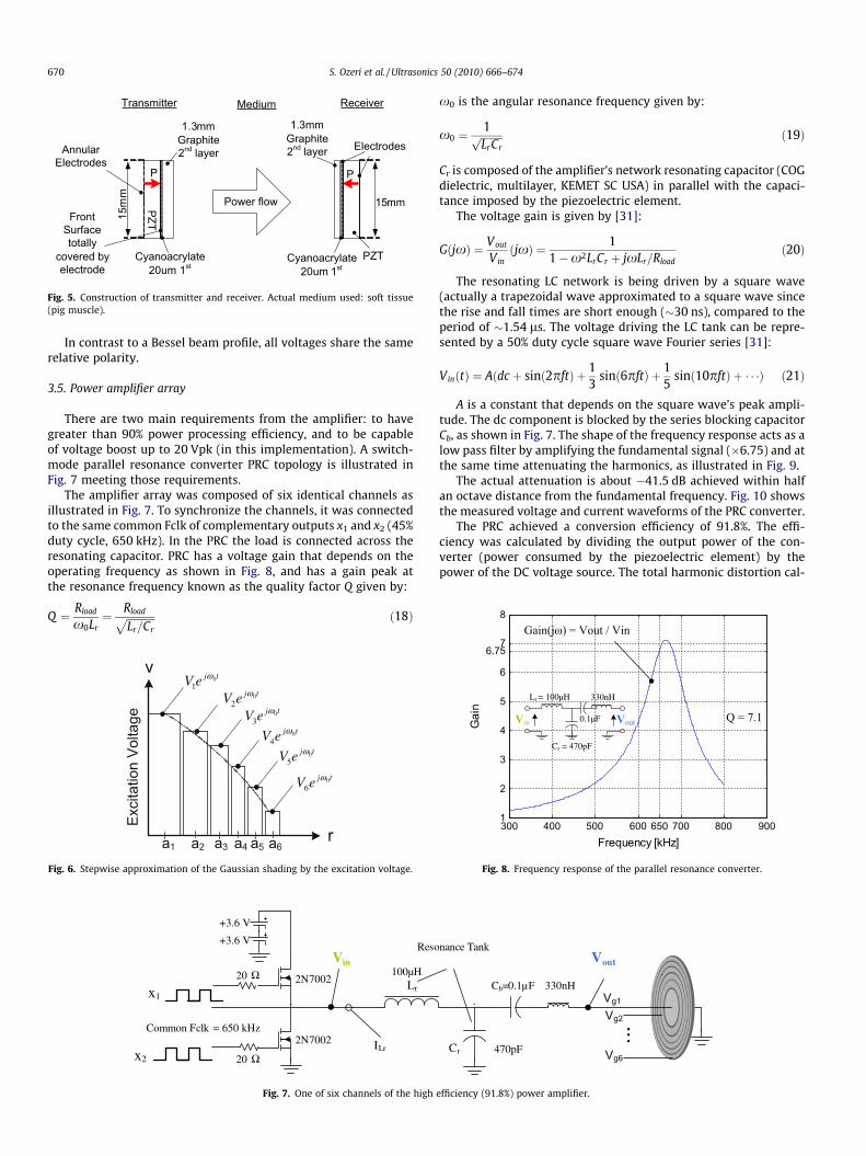
3.5. Power amplifier array
There are two main requirements from the amplifier: to havegreater than 90% power processing efficiency, and to be capableof voltage boost up to 20 Vpk (in this implementation). A switch-mode parallel resonance converter PRC topology is illustrated inFig. 7 meeting those requirements.
The amplifier array was composed of six identical channels asillustrated in Fig. 7. To synchronize the channels, it was connectedto the same common Fclk of complementary outputs x1 and x2 (45%duty cycle, 650 kHz). In the PRC the load is connected across theresonating capacitor. PRC has a voltage gain that depends on theoperating frequency as shown in Fig. 8, and has a gain peak atthe resonance frequency known as the quality factor Q given by:
Q ¼ Rload
x0Lr¼ Rloadffiffiffiffiffiffiffiffiffiffiffi
Lr=Cr
p ð18Þ
01
j tV e ω
02
j tV e ω
03
j tV e ω
04
j tV e ω
05
j tV e ω
06
j tV e ω
Fig. 6. Stepwise approximation of the Gaussian shading by the excitation voltage.
+3.6 V
Lr
ResoVin
ILr
100µH
.
Common Fclk = 650 kHz
20
2N7002
2N7002
20 x2
x1
+3.6 V
Ω
Ω
Fig. 7. One of six channels of the high
x0 is the angular resonance frequency given by:
x0 ¼1ffiffiffiffiffiffiffiffiffiLrCrp ð19Þ
Cr is composed of the amplifier’s network resonating capacitor (COGdielectric, multilayer, KEMET SC USA) in parallel with the capaci-tance imposed by the piezoelectric element.
The voltage gain is given by [31]:
GðjxÞ ¼ Vout
VinðjxÞ ¼ 1
1�x2LrCr þ jxLr=Rloadð20Þ
The resonating LC network is being driven by a square wave(actually a trapezoidal wave approximated to a square wave sincethe rise and fall times are short enough (�30 ns), compared to theperiod of �1.54 ls. The voltage driving the LC tank can be repre-sented by a 50% duty cycle square wave Fourier series [31]:
VinðtÞ ¼ Aðdc þ sinð2pftÞ þ 13
sinð6pftÞ þ 15
sinð10pftÞ þ � � �Þ ð21Þ
A is a constant that depends on the square wave’s peak ampli-tude. The dc component is blocked by the series blocking capacitorCb, as shown in Fig. 7. The shape of the frequency response acts as alow pass filter by amplifying the fundamental signal (�6.75) and atthe same time attenuating the harmonics, as illustrated in Fig. 9.
The actual attenuation is about �41.5 dB achieved within halfan octave distance from the fundamental frequency. Fig. 10 showsthe measured voltage and current waveforms of the PRC converter.
The PRC achieved a conversion efficiency of 91.8%. The effi-ciency was calculated by dividing the output power of the con-verter (power consumed by the piezoelectric element) by thepower of the DC voltage source. The total harmonic distortion cal-
Vout
Cr
Cb=0.1µF
nance Tank
.
.
330nH
470pF
...
Vg1
Vg2
Vg6
efficiency (91.8%) power amplifier.
300 400 500 600 700650 800 9001
2
3
4
5
6
6.757
Frequency [kHz]
Gai
n
Lr = 100µH
Cr = 470pF
outin
330nH
0.1µF
Fig. 8. Frequency response of the parallel resonance converter.
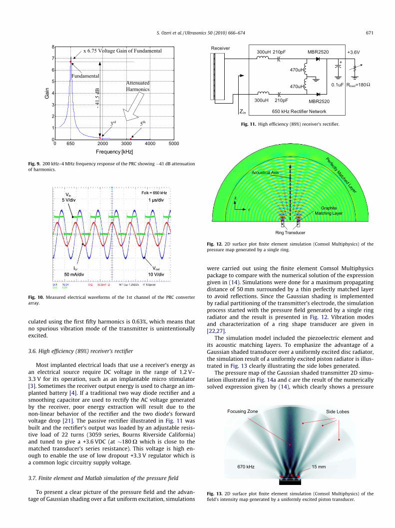
Fig. 10. Measured electrical waveforms of the 1st channel of the PRC converterarray.
+
Receiver
470uH
470uH
300uH 210pF MBR2520
MBR2520
0.1uF Rload=180
Zin 650 kHz Rectifier Network
300uH 210pF
+3.6V
Ω
Fig. 11. High efficiency (89%) receiver’s rectifier.
r
z
Acoustical Axis
Ring Transducer
Graphite Matching Layer
Perfectly Matched Layer
Fig. 12. 2D surface plot finite element simulation (Comsol Multiphysics) of thepressure map generated by a single ring.
0 650 2000 3000 4000 50000
1
2
3
4
5
6
7
8
Frequency [kHz]
Gai
n
Fig. 9. 200 kHz–4 MHz frequency response of the PRC showing �41 dB attenuationof harmonics.
Side LobesFocusing Zone
670 kHz 15 mm
Fig. 13. 2D surface plot finite element simulation (Comsol Multiphysics) of thefield’s intensity map generated by a uniformly excited piston transducer.
S. Ozeri et al. / Ultrasonics 50 (2010) 666–674 671
culated using the first fifty harmonics is 0.63%, which means thatno spurious vibration mode of the transmitter is unintentionallyexcited.
3.6. High efficiency (89%) receiver’s rectifier
Most implanted electrical loads that use a receiver’s energy asan electrical source require DC voltage in the range of 1.2 V–3.3 V for its operation, such as an implantable micro stimulator[3]. Sometimes the receiver output energy is used to charge an im-planted battery [4]. If a traditional two way diode rectifier and asmoothing capacitor are used to rectify the AC voltage generatedby the receiver, poor energy extraction will result due to thenon-linear behavior of the rectifier and the two diode’s forwardvoltage drop [21]. The passive rectifier illustrated in Fig. 11 wasbuilt and the rectifier’s output was loaded by an adjustable resis-tive load of 22 turns (3059 series, Bourns Riverside California)and tuned to give a +3.6 VDC (at �180 X which is close to thematched transducer’s series resistance). This voltage is high en-ough to enable the use of low dropout +3.3 V regulator which isa common logic circuitry supply voltage.
3.7. Finite element and Matlab simulation of the pressure field
To present a clear picture of the pressure field and the advan-tage of Gaussian shading over a flat uniform excitation, simulations
were carried out using the finite element Comsol Multiphysicspackage to compare with the numerical solution of the expressiongiven in (14). Simulations were done for a maximum propagatingdistance of 50 mm surrounded by a thin perfectly matched layerto avoid reflections. Since the Gaussian shading is implementedby radial partitioning of the transmitter’s electrode, the simulationprocess started with the pressure field generated by a single ringradiator and the result is presented in Fig. 12. Vibration modesand characterization of a ring shape transducer are given in[22,27].
The simulation model included the piezoelectric element andits acoustic matching layers. To emphasize the advantage of aGaussian shaded transducer over a uniformly excited disc radiator,the simulation result of a uniformly excited piston radiator is illus-trated in Fig. 13 clearly illustrating the side lobes generated.
The pressure map of the Gaussian shaded transmitter 2D simu-lation illustrated in Fig. 14a and c are the result of the numericallysolved expression given by (14), which clearly shows a pressure

5 10 15 20 25 30 35 40 45 500
0.2
0.4
0.6
0.8
1
1.2
Nor
miliz
ed P
ress
ure
Distance From Radiating Surface [mm]
120kPa peak
HydrophoneTransmitter
5 – 50mm
Acoustical Axis
Fig. 15. Pressure measured along the acoustic axis through water, normalized to120 kPa.
Fig. 14. (a) Matlab numerical solution, and (b) finite element simulation of the pressure field generated by the stepwise approximated Gaussian shaded transducer.
672 S. Ozeri et al. / Ultrasonics 50 (2010) 666–674
map that is similar to what is achieved by the finite element sim-ulation given in (b and d).
Power transfer efficiency depends on the field intensity shapewhich is proportional to the pressure squared, therefore intensityis more concentrated than the pressure field. Maximum sourcepower to DC load power efficiency achieved is 39.1% when thetransmitter and receiver are optimally oriented (zero lateral shiftbetween the transducers). Efficiency decreased to 17.2% at a dis-tance of 40 mm as the result of accumulated tissue absorptionand the spread of the field’s intensity with the increased distancebetween the transducers. Power transfer efficiency was calculatedby dividing the measured DC load power Pout by the transmitter’sconsumed power Pin. The transmitter’s power was measured byusing the multiplication feature of the oscilloscope to multiplythe instantaneous transmitter’s voltage and current of each con-centric element, and then averaging the result. Electrical wave-forms were recorded using a TDS5054, 500 MHz, four channeloscilloscope along with P5050 voltage probes and CT-2 currentprobes with a transducer sensitivity of 1 mV/mA (all of which aremanufactured by Tektronix, Oregon, USA). The efficiency calcula-tion included the rectifier loss that achieved a high efficiency of89%, high enough not to need synchronous rectification.
To verify the performance of the UTET link, measurements ofultrasound radiation and energy transfer were conducted withina water tank, using water at a room temperature of 25 �C. Distilledwater served as a medium for acoustic wave pressure measure-ments, since its acoustic impedance is close to that of soft biolog-ical tissue and allows the hydrophone to be easily moved in orderto map the pressure pattern. This serves as a first-order proof-of-concept. The test tank was fabricated out of 6 mm thick Perspexplates and has dimensions of 40 � 20 � 20 cm. In order to avoidreflections from the test tank walls, these were covered with a10 mm thick ultrasonic absorber sheet, Aptflex F28, attached tothe internal side walls by APTBOND B1 bond (both manufacturedby Precision Acoustics, Dorchester UK). Pressure was measuredalong the acoustic axis using a miniature hydrophone probe(TC4038, manufactured by Reson, Slangerup Denmark) which has
a sensitivity of �224.5 dB ± 2 dB at 650 kHz re 1 V/lPa (�228dB ± 2 dB at 100 kHz). Measurement results of the pressure ampli-tude recorded at intervals of 1 mm along the acoustic axis, gener-ated by the Gaussian shaded transmitter, are presented in Fig. 15.
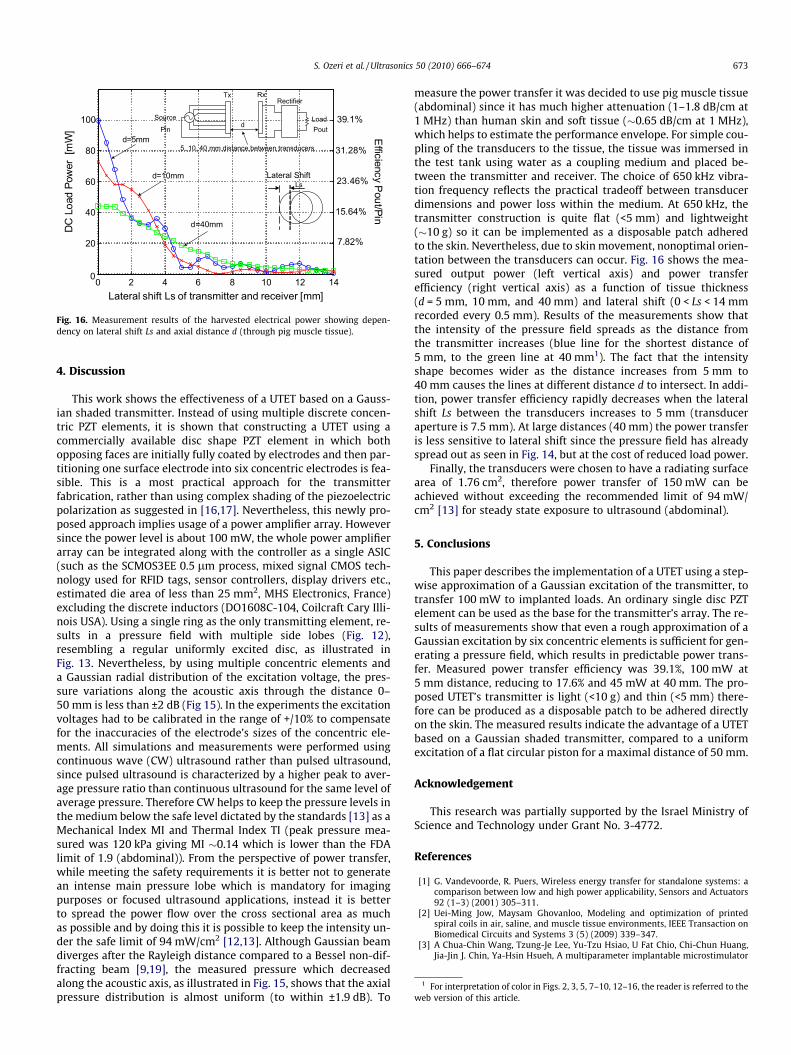
Although skin and the underlying soft tissue layer have acousticimpedances and phase velocities that are close to those of distilledwater, the attenuation of the pressure field by tissue is much largerthan water attenuation (soft tissue 0.6–1.5 dB/cm compared towater 0.002 dB/cm at 1 MHz) [28,29]. To account for the tissuelosses, power transfer measurements were conducted using bulkpig muscle tissue (abdominal) [23] that was immersed in the waterinside the test tank between the transmitter and receiver. Fig. 16shows the measured output power and calculated efficiency as afunction of the tissue (pig muscle, �1.8 dB/cm at 1 MHz) thicknessd, and lateral shift Ls. Transmitter power of Pin = 256 mW was keptconstant as a power reference during all load power measure-ments, since it yielded a load power of 100 mW at the shortest dis-tance d of 5 mm.
0 2 4 6 8 10 12 140
DC
Load
Pow
er[m
W]
Lateral shift Ls of transmitter and receiver [mm]
d=5mm
d=10mm
39.1%
31.28%
23.46%
15.64%
7.82%
Efficiency
Pout/Pin
d=40mm
100
80
60
40
20
Loadd
RectifierTx Rx
Source
Pin Pout
5, 10, 40 mm distance between transducers
LsLateral Shift
Fig. 16. Measurement results of the harvested electrical power showing depen-dency on lateral shift Ls and axial distance d (through pig muscle tissue).
1 For interpretation of color in Figs. 2, 3, 5, 7–10, 12–16, the reader is referred to theweb version of this article.
S. Ozeri et al. / Ultrasonics 50 (2010) 666–674 673
4. Discussion
This work shows the effectiveness of a UTET based on a Gauss-ian shaded transmitter. Instead of using multiple discrete concen-tric PZT elements, it is shown that constructing a UTET using acommercially available disc shape PZT element in which bothopposing faces are initially fully coated by electrodes and then par-titioning one surface electrode into six concentric electrodes is fea-sible. This is a most practical approach for the transmitterfabrication, rather than using complex shading of the piezoelectricpolarization as suggested in [16,17]. Nevertheless, this newly pro-posed approach implies usage of a power amplifier array. Howeversince the power level is about 100 mW, the whole power amplifierarray can be integrated along with the controller as a single ASIC(such as the SCMOS3EE 0.5 lm process, mixed signal CMOS tech-nology used for RFID tags, sensor controllers, display drivers etc.,estimated die area of less than 25 mm2, MHS Electronics, France)excluding the discrete inductors (DO1608C-104, Coilcraft Cary Illi-nois USA). Using a single ring as the only transmitting element, re-sults in a pressure field with multiple side lobes (Fig. 12),resembling a regular uniformly excited disc, as illustrated inFig. 13. Nevertheless, by using multiple concentric elements anda Gaussian radial distribution of the excitation voltage, the pres-sure variations along the acoustic axis through the distance 0–50 mm is less than ±2 dB (Fig 15). In the experiments the excitationvoltages had to be calibrated in the range of +/10% to compensatefor the inaccuracies of the electrode’s sizes of the concentric ele-ments. All simulations and measurements were performed usingcontinuous wave (CW) ultrasound rather than pulsed ultrasound,since pulsed ultrasound is characterized by a higher peak to aver-age pressure ratio than continuous ultrasound for the same level ofaverage pressure. Therefore CW helps to keep the pressure levels inthe medium below the safe level dictated by the standards [13] as aMechanical Index MI and Thermal Index TI (peak pressure mea-sured was 120 kPa giving MI �0.14 which is lower than the FDAlimit of 1.9 (abdominal)). From the perspective of power transfer,while meeting the safety requirements it is better not to generatean intense main pressure lobe which is mandatory for imagingpurposes or focused ultrasound applications, instead it is betterto spread the power flow over the cross sectional area as muchas possible and by doing this it is possible to keep the intensity un-der the safe limit of 94 mW/cm2 [12,13]. Although Gaussian beamdiverges after the Rayleigh distance compared to a Bessel non-dif-fracting beam [9,19], the measured pressure which decreasedalong the acoustic axis, as illustrated in Fig. 15, shows that the axialpressure distribution is almost uniform (to within ±1.9 dB). To
measure the power transfer it was decided to use pig muscle tissue(abdominal) since it has much higher attenuation (1–1.8 dB/cm at1 MHz) than human skin and soft tissue (�0.65 dB/cm at 1 MHz),which helps to estimate the performance envelope. For simple cou-pling of the transducers to the tissue, the tissue was immersed inthe test tank using water as a coupling medium and placed be-tween the transmitter and receiver. The choice of 650 kHz vibra-tion frequency reflects the practical tradeoff between transducerdimensions and power loss within the medium. At 650 kHz, thetransmitter construction is quite flat (<5 mm) and lightweight(�10 g) so it can be implemented as a disposable patch adheredto the skin. Nevertheless, due to skin movement, nonoptimal orien-tation between the transducers can occur. Fig. 16 shows the mea-sured output power (left vertical axis) and power transferefficiency (right vertical axis) as a function of tissue thickness(d = 5 mm, 10 mm, and 40 mm) and lateral shift (0 < Ls < 14 mmrecorded every 0.5 mm). Results of the measurements show thatthe intensity of the pressure field spreads as the distance fromthe transmitter increases (blue line for the shortest distance of5 mm, to the green line at 40 mm1). The fact that the intensityshape becomes wider as the distance increases from 5 mm to40 mm causes the lines at different distance d to intersect. In addi-tion, power transfer efficiency rapidly decreases when the lateralshift Ls between the transducers increases to 5 mm (transduceraperture is 7.5 mm). At large distances (40 mm) the power transferis less sensitive to lateral shift since the pressure field has alreadyspread out as seen in Fig. 14, but at the cost of reduced load power.
Finally, the transducers were chosen to have a radiating surfacearea of 1.76 cm2, therefore power transfer of 150 mW can beachieved without exceeding the recommended limit of 94 mW/cm2 [13] for steady state exposure to ultrasound (abdominal).
5. Conclusions
This paper describes the implementation of a UTET using a step-wise approximation of a Gaussian excitation of the transmitter, totransfer 100 mW to implanted loads. An ordinary single disc PZTelement can be used as the base for the transmitter’s array. The re-sults of measurements show that even a rough approximation of aGaussian excitation by six concentric elements is sufficient for gen-erating a pressure field, which results in predictable power trans-fer. Measured power transfer efficiency was 39.1%, 100 mW at5 mm distance, reducing to 17.6% and 45 mW at 40 mm. The pro-posed UTET’s transmitter is light (<10 g) and thin (<5 mm) there-fore can be produced as a disposable patch to be adhered directlyon the skin. The measured results indicate the advantage of a UTETbased on a Gaussian shaded transmitter, compared to a uniformexcitation of a flat circular piston for a maximal distance of 50 mm.
Acknowledgement
This research was partially supported by the Israel Ministry ofScience and Technology under Grant No. 3-4772.
References
[1] G. Vandevoorde, R. Puers, Wireless energy transfer for standalone systems: acomparison between low and high power applicability, Sensors and Actuators92 (1–3) (2001) 305–311.
[2] Uei-Ming Jow, Maysam Ghovanloo, Modeling and optimization of printedspiral coils in air, saline, and muscle tissue environments, IEEE Transaction onBiomedical Circuits and Systems 3 (5) (2009) 339–347.
[3] A Chua-Chin Wang, Tzung-Je Lee, Yu-Tzu Hsiao, U Fat Chio, Chi-Chun Huang,Jia-Jin J. Chin, Ya-Hsin Hsueh, A multiparameter implantable microstimulator

674 S. Ozeri et al. / Ultrasonics 50 (2010) 666–674
SOC, IEEE Transactions on Very Large Scale Integration (VLSI) Systems 13 (12)(2005) 1399–1402.
[4] Chi-Chun Huang, Shou-Fu Yen, Chua-Chin Wang, A Li-ion battery chargingdesign for biomedical implants, APCCAS IEEE Asia Pacific Conference onCircuits and Systems 30 (3) (2008) 400–403.
[5] G.V.B. Cochran, M.P. Kadaba, V.R. Palmieri, External ultrasound can generatemicroampere direct currents in vivo from implanted piezoelectric materials,Journal of Orthopaedic Research 6 (1988) 145–147.
[6] S. Ozeri, D. Shmilovitz, Ultrasonic transcutaneous energy transfer for poweringimplanted devices, Ultrasonics 50 (6) (2010) 556–566.
[7] D.T. Blackstock, Physical Acoustics, John Wiley Publications, 2000. pp. 440–457.
[8] J. Zemanek, Beam behavior within the near field of a vibrating piston, Journalof the Acoustical Society of America 49 (1971) 181–191.
[9] J.A. Campbell, S. Soloway, Generation of a nondiffracting beam with frequencyindependent beamwidth, Journal of the Acoustical Society of America 88 (5)(1990) 2467–2477.
[10] J. Durnin, Miceli Jr., Diffraction-free beams, Physical Review Letters 58 (15,13)(1987) 1499–1501.
[11] H. Masuyama, T. Yokoyama, K. Nagai, K. Mizutani, Generation of Bessel beamfrom equiamplitude-driven annular transducer array consisting of a fewelements, Japanese Journal of Applied Physics 38 (1999) 3080–3084.
[12] S. Felkel, Ultrasound safety: mechanical and thermal indices: a primer, Journalof Diagnostic Medical Sonography 15 (1999) 77–80.
[13] US Department of Health and Human Services, Food and Drug Administration,Center for Devices and Radiological Health, Information for ManufacturersSeeking Marketing Clearance of Diagnostic Ultrasound Systems andTransducers, 9 September 2008.
[14] D. Huang, M. Breazeale, An ultrasonic gaussian transducer and its diffractionfield, IEEE Transactions on Ultrasonics, Ferroelectrics and Frequency Control53 (5) (2006) 1018–1027.
[15] J.F. Kelly, R.J. McGough, An annular superposition integral for axisymmetricradiators, Journal of the Acoustical Society of America 121 (2) (2007) 759–765.
[16] H. Calas et al., Non-uniformly polarized piezoelectric modal transducer:fabrication method and experimental results, Smart Materials and Structures15 (2006) 904–908.
[17] D.K. Hsu et al., Non-uniformly poled gaussian and Bessel function transducers,Ultrasonics Symposium (1989) 789–792.
[18] K.A. Snook, C.-H. Hu, T.R. Shrout, K. Shung, High frequency ultrasound annulararray imaging. Part I: array design and fabrication, IEEE Transactions onUltrasonics, Ferroelectrics and Frequency Control 53 (2) (2006) 300–308.
[19] Jian-Yu Lu, James F. Greenleaf, Ultrasonic nondiffracting transducer formedical imaging, IEEE Transactions on Ultrasonics, Ferroelectrics andFrequency Control 37 (5) (1990) 438–447.
[20] T. Inoue, M. Ohta, S. Takahashi, Design of ultrasonic transducers with multipleacoustic matching layers for medical application, IEEE Transactions onUltrasonics, Ferroelectrics and Frequency Control UFFC-34 (1) (1987) 8–16.
[21] S. Ben-Yaakov, N. Krihely, Resonant rectifier for piezoelectric sources, IEEEApplied Power Electronics Conference, APEC (2005) 249–253.
[22] K.C. Cheng, H.L.W. Chan, Characterization of piezoelectric ring used for wirebonding transducer application, in: Electron Device Meeting, Proceedings,Hong Kong, 2001, pp. 64–67.
[23] P.A. Lewin, H. Busk, In-vivo ultrasonic measurements of tissue properties,Ultrasonics Symposium (1982) 709–712.
[24] R.A. Eno, Pyrolytic Carbon Transmyocardial Implant, United States Patent6113823, 09/05/2000.
[25] Pyrolytic carbon for biomedical applications, <http://www.azom.com/details.asp>, 2008 (accessed 6.08).
[26] J.R. Davis, Handbook of Materials for Medical Devices, ASM International (2003).[27] P.J. Kielczynski, W. Pajewski, M. Szalewski, Ring piezoelectric transducers
radiating ultrasonic energy into the air, IEEE Transactions on Ultrasonics,Ferroelectrics and Frequency Control 37 (1) (1990) 38–43.
[28] <http://www.kayelaby.npl.co.uk/general_physics/2_4/2_4_6.html>, 2009(accessed 11.09).
[29] Francis A Duck, Andrew C Baker, Hazel C Starritt, Ultrasound in Medicine,Institute of Physics Publishing, 1998, pp. 57–88.
[30] P.J. Stevenson, D.A. Hall, Characteristic P-E and S-E relationships of hard PZTceramics under high drive conditions, in: Proceedings of the Tenth IEEEInternational Symposium on Applications of Ferroelectrics. ISAF, vol. 1, August1996, pp. 313–316.
[31] R.W. Erickson, D. Maksimovic, Fundamentals of Power Electronics, second ed.,Kluwer Academic Publishing, 2001, pp. 709–721.