ultrasonic phased array tools for composite inspection ...figure 2: 0° electronic scanning...
TRANSCRIPT

17th World Conference on Nondestructive Testing, 25-28 Oct 2008, Shanghai, China
Ultrasonic Phased Array tools for composite inspection during maintenance and manufacturing
Jason HABERMEHL, Andre LAMARRE
Olympus NDT 505 Boul. Technologique, Quebec City, Quebec, Canada, G1P4S9
Tel: 1-418-872-1155, Fax: 1-418-872-5431 E-mail:[email protected] Web: www.olympusndt.com
Abstract
Aircraft manufacturers, maintenance service providers, and airline operators have recently started to use ultrasonic phased-array technology to ensure the quality of their composite parts during maintenance and manufacturing. Olympus NDT has developed various solutions with its phased-array instruments like the OmniScan™ PA, the Focus LT™ and TomoView™ to meet the most demanding requirements. Phased-array probes and holders were specifically designed for the inspection of composite flat panels and corners. These tools combined with composite specific software features provide greater productivity while maintaining a high degree of reliability. This paper summarizes the advantages and the benefits obtained by the use of this technology. Keywords: phased-array, composites, maintenance, manufacturing, corners, flat panels, probes, probe holders, scanners 1. Flat Panel Inspections
Typical Carbon Fibre Reinforced Polymer (CFRP) parts that consist of one or more relatively
large and flat sections in the aerospace industry include skins, flanges and webs of stringers and spars to name a few. Traditional inspections using conventional ultrasound have the disadvantage of being slow and tedious. UT phased arrays have the ability to inspect these large structures quickly and reliably. Many advanced inspection systems exist for in-house testing. However, the same technology is required more and more for in-service inspections where a large inspection unit is not always available, feasible or cost-effective. An advanced ultrasonic completely portable inspection unit with two-dimensional encoding capabilities is a huge asset for all types of inspection requirements. In maintenance or production settings, the Omniscan™ PA 16:128 unit fits the bill for inspection requirements.
The OmniScan™ PA uses appropriate probe holders and a linear array composed of 64 to 128 elements firing in sequence to cover a large area in a single pass. Furthermore, the unit provides multiple amplitude or time-of-flight C-scan mapping views that make data analysis an easy task. The main advantages of using the OmniScan™ PA with this technique are the increased inspection speed due to the large coverage of the phased array probe and the portability of the equipment. In terms of one-line scanning speed, a typical set-up can inspect a 60mm band at roughly 100mm per second. The 16:128 module also offers one-button swapping from phased array mode to conventional ultrasonic mode for quick verification and defect sizing useful for certain code requirement applications.

An important aspect when dealing with non-immersion inspections of large surfaces is the reliability of the coupling medium. The surface finish and geometry greatly influences the choice of probe holder that will work the best. Olympus offers multiple probe holders to meet these needs. Typically the standard rexolite probe holder and the water pocket variation to the standard probe holder are well adapted to most inspection requirements. The water pocket wedge has a 0.005" groove on the bottom of the wedge to allow for a thin film of water to maintain excellent coupling with the part. Both of these wedges offer the possibility for irrigation through channels in the wedge and are also employable by simply spraying a mix of water and soap or coupling over the part surface.
For mapping purposes, one-line scans or two-dimensional scans are easily performed with either a wheel encoder or a two-axis "Glider" scanner. The Glider is easily mounted and placed on almost any flat or relatively flat panel. Suction cups hold the scanner in place even on vertical surfaces.
Figure 1: Olympus NDT typical flat panel composite kit including the OmniScan MX PA, the Glider scanner and the near-wall phased array probe (left); the 64 element near-wall phased array probe and water pocket
rexolite wedge (right)
A zero-degree electronic scan is performed through successive firing of the elements.
Sensitivity calibration ensures the same signal amplitude from each beam of the electronic scan. Typical gate set-ups use one gate (Gate A) to measure time-of-flight and amplitude from immediately after the front wall echo until past the backwall echo. This gate allows the display of two C-scans: the amplitude in gate A (A%) and the time-of-flight (TOF) or thickness. The second gate (Gate B) can be used to monitor the backwall on constant thickness panels. This gate allows the display of the backwall amplitude C-scan (B%). The Omniscan allows the user to calibrate a time corrected gain (TCG) correction from a standard panel or to manually input the required gain as a function of depth. This is a requirement for obtaining relevant C-scans.
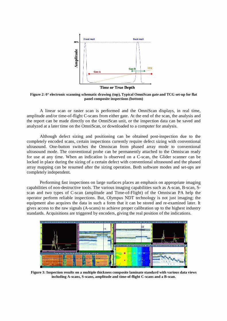
Figure 2: 0° electronic scanning schematic drawing (top), Typical OmniScan gate and TCG set-up for flat
panel composite inspections (bottom)
A linear scan or raster scan is performed and the OmniScan displays, in real time,
amplitude and/or time-of-flight C-scans from either gate. At the end of the scan, the analysis and the report can be made directly on the OmniScan unit, or the inspection data can be saved and analyzed at a later time on the OmniScan, or downloaded to a computer for analysis.
Although defect sizing and positioning can be obtained post-inspection due to the completely encoded scans, certain inspections currently require defect sizing with conventional ultrasound. One-button switches the Omniscan from phased array mode to conventional ultrasound mode. The conventional probe can be permanently attached to the Omniscan ready for use at any time. When an indication is observed on a C-scan, the Glider scanner can be locked in place during the sizing of a certain defect with conventional ultrasound and the phased array mapping can be resumed after the sizing operation. Both software modes and set-ups are completely independent.
Performing fast inspections on large surfaces places an emphasis on appropriate imaging capabilities of non-destructive tools. The various imaging capabilities such as A-scan, B-scan, S-scan and two types of C-scan (amplitude and Time-of-Flight) of the Omniscan PA help the operator perform reliable inspections. But, Olympus NDT technology is not just imaging; the equipment also acquires the data in such a form that it can be stored and re-examined later. It gives access to the raw signals (A-scans) to achieve proper calibration up to the highest industry standards. Acquisitions are triggered by encoders, giving the real position of the indications.
Figure 3: Inspection results on a multiple thickness composite laminate standard with various data views
including A-scans, S-scans, amplitude and time-of-flight C-scans and a B-scan.

2. Corner Inspections
Typical Carbon Fibre Reinforced Polymers (CFRP) parts often consist of corners that require inspection as much as the flat sections of the same part. These parts in the aerospace industry can be found on most spars, stringers and hollow hats. Typical corner inspections are performed in a manufacturing environment. Inspection of these corners is relatively new but is becoming more and more important with the increasing production of CFRP laminate aircraft structures. Traditional inspections are performed manually with a conventional ultrasonic probe. The slow and tedious nature of this inspection approach and the strong dependency on the inspector are major disadvantages.
The OmniScan™ PA uses appropriate probe holders and curved linear arrays composed of 16 to 64 elements firing in sequence to cover the entire corner in a single pass. The inspection of the entire corner becomes an encoded one-line scan. The geometry of the probe allows for all of the ultrasonic beams to coincide with the surface of the part perpendicularly in a manner homologous to flat surface inspections. Furthermore, the unit provides multiple amplitude or time-of-flight C-scan mapping views that make data analysis an easy task. In addition to the advantages previously mentioned for flat part inspections, the main advantages of using the OmniScan™ PA for this application is the possibility of covering the entire corner in one simple scan and obtaining completely encoded results for sizing. With respect to inspection speed, a typical set-up can inspect along a corner at roughly 200mm per second.
The probe and probe holder are judiciously chosen and positioned according to the corner geometry. The probe holder must be chosen so that the center of radius of the probe coincides with the center of radius of the corner. In this manner, the same probe can be used for a plurality of corner geometries by simply changing or adjusting the probe holder. Analogous approaches can be applied for inspecting from inside the corner as well as from outside the corner. Olympus NDT offers multiple probes and probe holders to meet these needs including adjustable immersion wedges that are adaptable to a range of corner radii.
Figure 4: Phased array radius probes and variable immersion wedge
A zero-degree electronic scan is performed through successive firing of the elements.
With the probe positioned correctly, the inspection becomes identical to a 0° flat inspection as each focal law intersects the surface perpendicularly. The front wall of the corner of the part is viewed as a straight horizontal interface. The gate set-ups for C-scan displays are almost identical to the flat part inspection set-up. However, the OmniScan™ PA allows A-scans to be synchronized to an interface gate (I) which allows for a certain degree of flexibility with respect

to the probe position with respect to the radius. The data gates A and B as well as the TCG correction are all synchronized to the interface gate.
Figure 5: Inspection results on a composite corner sample with various data views including A-scans, S-scans
and amplitude and time-of-flight C-scans.
The main difference between inspecting the corners in this way and inspecting a flat
panel is the correlation required for index sizing on the corners. Indication sizing in the scan direction can be directly measured from the encoded readings and the displays on the Omniscan. A geometric conversion taking into account the radius of the phased array probe (R), the radius of the corner (r), the depth of the indication (d), the thickness of the part (t) and the indication size as displayed on the Omniscan (C) is required to obtain the actual indication size (S). This conversion is also dependant on the type of inspection (ID or OD).
Figure 6: Radius index defect size correction diagrams and formula
3. Data Analysis
Olympus NDT has developed an automated defect size analysis tool for TomoView™ in collaboration with an aircraft manufacturer. The SNR (signal-to-noise ratio) utility provides a measure of the total defect area confined between user-positioned cursors by taking into account the mean background signal in a reference area near the defect in question. The signal-to-noise ratio used to define what constitutes a defect can be user defined. A histogram shows the amplitude or time-of-flight distribution of the cursor limited zone. The utility also incorporates a "binarizer" for easy defect imaging on a C-scan with a three-color palette.

Figure 7: TomoViewTM Signal-to-Noise Ratio utility control box and typical C-scan results
4. Benefits of Phased Array Ultrasound
There are a multitude of benefits associated with using phased array ultrasound for inspecting flat and corner composite parts. Notably, the enhanced data imaging reduces the human-error factor. In this sense, the use of C-scan images increases the reliability of the inspection because it guarantees full coverage of the inspected surface. Also, the large multi-element probes increase inspection speed and resolution. Combined with an appropriate scanner, large flat surfaces can be inspected quite reliably by encoding the entire inspection. The entire curved portion of various corner geometries can be inspected in one pass with linear encoding along the axial direction for defect positioning and sizing. Additionally, the storage of A-scan and C-scan data allows further analysis or periodic comparisons. Furthermore, with the OmniScan™ PA the same instrument supports phased array and conventional ultrasonic modes for quick swapping between the two techniques. 5. Conclusion
The Omniscan PA 16:128 and the Glider scanner combined with phased array or conventional probes offers a completely portable inspection solution for large area flat inspections of CFRP components. The same ultrasonic acquisition unit combined with curved phased array probes and probe holders offers a completely portable inspection solution for corner inspections of composite parts.