ultrasonic phased array testing of complex aircraft · pdf fileultrasonic phased array testing...
TRANSCRIPT
Ultrasonic Phased Array Testing of Complex Aircraft Structures
Ernst RAU, Ernst GRAUVOGL , Holger MANZKE, EADS Mil., Manching, Germany Philippe CYR, Olympus NDT, Québec, Canada
1. Introducion:
EADS Military aircraft is working on evaluation of modern ultrasonic equipment and coupling systems, for maintenance conditions and final assembly aircraft with focus on modern CFRP structures and corrosion problems on aging aircraft. To get the state of the art, a lot of approaches from conventional UT up to ultrasonic phased array have been investigated so far. The use of a high mobile phased array equipment allows a very comfortable and fast ultrasonic inspection and makes inspections of complex aircraft structures possible. With respect to the aircraft maintenance conditions, the report will describe the development of ultrasonic testing up to ultrasonic phased array testing during the so called B-Scan Project, the advantages and also the physical limits of this inspection method.
2. Principle of Pulse Echo Ultrasonic Testing by Scanning with a Longitudinal Wave:
In a single probe, an electrical pulse drives a piezo crystal. The result is a mechanical vibration and a sound beam. In air there is a sound velocity of 333 m/sec., in materials like CFRP about 3000 m/sec., in Aluminium about 6320 m/sec for example. Big changes in the sound impedance resulting in a big loss of energy in the sound beam, a disadvantage for ultrasonic testing. Due to this great changes in sound impedance, coupling is necessary to bring the sound bundle into the material, for example water with a sound velocity of 1483 m/s. When the sound beam is reaching the backwall, dependent to the change of sound velocities, a reflection of the beam will result. During the inspection we are looking for two pieces of relevant information, the running time of the beam and the reflected energy of the sound beam in one screen:
ECNDT 2006 - Tu.1.1.2
1

This is the information of one point in the inspection area called A-scan. If the probe is moving along a line, the result is a run of a lot of A-scans along 1 axis. This is a X-section of ultrasonic signals through the part called B-scan. If the probe is scanning in a 2nd axis, the result is a scan of a surface. The resultant image must be differentiated for c-scan amplitude and c-scan time of flight. Example:
Amplitude height (Power of sound beam)
Sound beam time-of-flight corresponds with thickness
B-Scan
C-Scan Amplitude (Echo C-Scan Time of flight
Fig. 1: A-Scan of a CFRP calibration
Fig. 2: Equipment under calibration procedure
Fig. 3: B-Scan Fig. 4: C-Scan Amplitude Fig. 5: B-Scan Time-of-Flight
2

A-Scan
Sectorial Scan Index axis (a Kind of B-Scan)
Sectorial-Scan Scan Axis
C-Scan Amplitude
C-Scan Time of Flight
Fig. 7: Scan of a CFRP Step wedge Specimen
Fig. 6: Sample with Impact Damage
3

The traditional way for scanning used a X/Y Scanner and a single probe scanning line by line, disadvantage, it is slow and low mobile. Advantage, very flexible coupling by a water filled slot and cheap probes.
Ultrasonic Testing with a X/Y Scanner
Fig. 8: X/Y Scanner on Flexi Track Fig. 9: Processing unit X/Y Scanner
Fig. 7: EADS CFRP Step wedge Specimen
4

3. Ultrasonic Phased Array Testing:
3.1 Principle Ultrasonic Phased Array Testing
In Ultrasonic phased array technique, an array is built as a bar with an accumulation of many small probes, in our case 128. Along this array, it is possible to produce a running sound beam along the scanning direction for the B-scan. To create a sound beam, an active group of elements is chosen, using an active group of elements step by step, the beam is running along the scanning direction. The 2 nd direction for a c-scan is recorded by an encoder.
UT Phased Array Probes
Fig. 10: Kinds of Ultrasonic Phased Array Probes
Fig. 11: Scheme of Sectorial Scanning
5

Sectorial scan of a monolithic CFRP area with Porosity
3.2 Challenge for phased Array systems: Good coupling and handling during aircraft maintenance conditions
The array built like a bar with a big flat plexi delay line does not work very well with double curved aircraft structures. There is also a risk, that painted surfaces will be damaged by scratches. For this reason, a flexible coupling system will be needed. Softwedges may the best constructions for such systems, used in service conditions.
Fig. 12: Resultant image of a Sectorial Scan
Fig. 12: 64 Element array on plexi delay line
6

3.2.1 Principle of Waterboxes:
A water delay is built up between a flexible diaphragm and an ultrasonic array. The flexible diaphragm follows the curves along the structure. Coupling on the surface is still necessary.
3.2.2 Commercial Waterbox.
Brushes
Sound beam window with diaphragm filled with water
4 small contact points on the edges
Wheel Encoder for C-scanning
Flexible Diagram Water Delayline
Ultrasonic Array Case
Fig. 13: Scheme of UT Phased Array Waterboxes
Fig. 14: Supplier Waterbox
7

The first tested water box was wobbly and unstable on curved surfaces, therefore no constant angle of incidence was given and consequently no reproduceable inspection results could be made during repeating inspections.
3.2.3 Improved Coupling Systems for Ultrasonic Phased Array In Service Inspections:
3.2.3.1 EADS Phased Array waterbox for 5 MHz, 128 Element Array:
Fig. 15: Commercial waterbox on curved CFRP structure
Fig. 16b: EADS Waterbox assembly Fig. 16a: EADS Waterbox without case
8

The EADS Waterboxes have several contact points in order to be very flexible to the inspection problem, so that a stable angle of incidence is given, disadvantage is a dead zone of minimum17 mm at the side of both waterboxes, but there is no possibility to minimizing it much more. The dead zone must be covered by an inspection with a single probe, if an edge of a part does not allow scanning to the edge. The symmetric construction and the small size are very good for handling and have a good performance on curved structures. At the resulting sectorial scan, the time delay of the curved structure is visible and is disturbing while processing with the gates. Gates are as a basic tool as a straight and does not follow the outline. A solution for this problem will be a triggering of the interface echo to the 0-position at the screen, visualized as a red bar, Fig. 19. How ever, it is necessary for the inspector to know , that there is a loss of amplitude height at the sides of the result screen, due to the tapered angle of incidence.
Fig. 17: Comparison of two Waterboxes for 5MHz Arrays
Contact points
Fig. 18: Waterbox stable via contact points on a curved aircraft structure
Dead zone about 17mm
9

3.2.3.2 Phased Array Water Box for 2.25 MHz, 128 Element Array:
The next version was a water box with a little integrated encoder in the box due to a better handling to inspectors.
Fig. 19: Water Box with Integrated small Encoder
Fig. 19: Sectorial Scan of Curved Structure
interface echo→
10
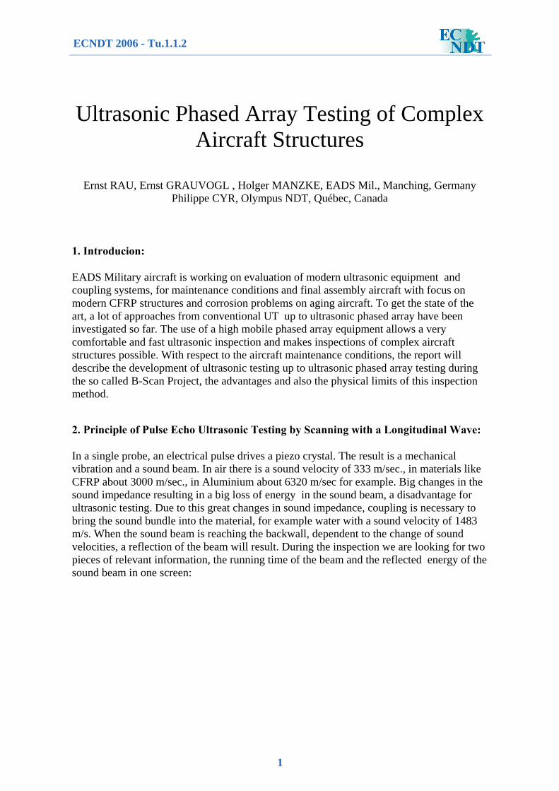
3.2.4 Wheel Probe
Fig. 20: Wheel Probe, NDT Solutions
Wheel around probe, probe inside
Encoder Wheel
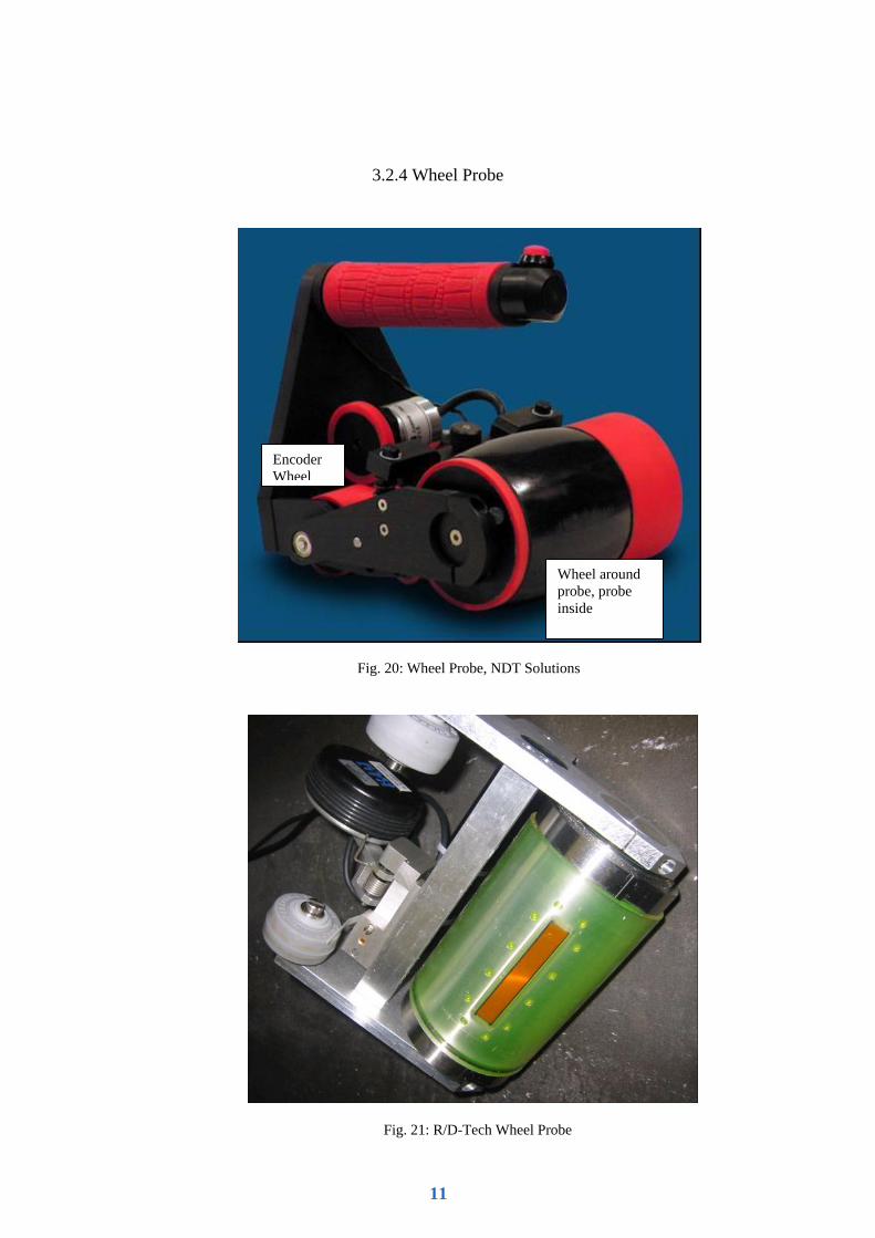
Fig. 21: R/D-Tech Wheel Probe
11

Another solution for coupling will be a wheel probe. Future experiments at EADS Mil. for this kind of coupling system will be made.
3.2.4 Polymer Softwedge for Array Systems:
Another usefull and cost effective application, if a very high flexibility of the coupling system is not needed is a softwedge. Disadvantage is, the delay line with 1050m/s sound velocity does have a higher sound attenuation as a water system, so more gain will be used
Fig. 22/23: Polymer Softwedge
12

to get a acceptable result from the backwall, resulting is a loss of the resolution at the upper layers in composite structures.
3.3 C-Scanning by a mobile Phased Array System:
The water box must be moved over the inspection area, which is covered by couplant. One axis is given by the array, the length of the scan is recorded by an encoder wheel. This kind of inspection is very quick, the system is very flexible for several kinds of inspections, the scanning process is very stable and fast and the resulting images are very good to handle while being processed by NDT personnel. The full data set can be stored on a flash card and a subsequent evaluation independent from the aircraft structure is possible by an evaluation software. Scan data can also be provided to other NDT personnel for discussion.
3.4 Possibilities and Used Cases for Beam Influence by Phased Array
Such a system is very flexible by using different time delays for the excitation pulse.
3.4.1 Beam focalisation:
In some cases, the exact depth of the defect to be found is known. For example a weld inspection. In such case, a beam focalisation is used to have the spot of the highest sound pressure and resulting a high resolution a depth. By applied time delay to several vibrator elements the focus depth can be programmed at a law file.
Fig. 24: Ultrasonic Phased Array Inspection on an EF2000 Aircraft
Processing Unit
Water Box with Encoding Wheel
13

For distance and gain calibration a special specimen is necessary, a calibration block with cross-holes is easy to build.
1 2
3
1. Electric pulse to several elements with different delays
2. Beam during focusing 3. Focused beam at the chosen depth
14

3.4.2 Steering Beam Inspection:
By Ultrasonic Phased Array is also the possibility to steer the beam around a used area under the array. By different calculated time delays of the electric excitation, the beam is steering between the calculated angles.
Fig. 25: Aluminium X-hole specimen
Fig. 26: C-Scan amplitude of Aluminium X-hole specimen
Highest resolution at the upper cross hole at 3.5mm
Loosing resolution with rising distance
15

At one used case, at a CFRP J-Spar sample, the spar was moving during the bonding process, following a constant radius is not given and the possibility for a delamination is rising. Maybe such areas must be monitored at the future. A steering beam inspection for areas with single side access is useful. On aircraft, a straight to handle the waterbox could be useful.
A steering beam of +/- 20° was used, radius refection visible on screen.
Fig. 27: Steering beam, excitated by different time delays
Fig. 28: Steering beam, excitated by different time delays
16

A defect is indicated by breaking down back wall echo and a rising defect echo.
4. Conclusions
The use of a high mobile phased array equipment allows a very comfortable and fast ultrasonic inspection under aircraft maintenance condition. The scans of the structures appear very plastic and give a good inspection tool to the inspector. Gate technique during Data evauluation is a good possibility to work out the defects from the scan by suppress the structure indications, so also not NDI people may get a feeling for a defect with less explanation. The sensors are very flexible for different inspection cases. The biggest problem is good coupling and also a constant angle of incedance, for reproduceable inspection results. EDAS is on a high level with the waterbox construction, but never the less, there are exciting problems to scan close to disturbing structures (see Fig. 17). There is still capable of improvement.
5. References
[1] Phased Array Technical Guidelines (R/D-Tech) [2] Training Paper Ultrasonic Testing Level 2 (Airbus: W.Bisle, H.-W. Conze, A. Kück, G. Wehmann)
Interface echo
Reflection of the radius
Defect indication
17