ultrasonic level sensor - ato.com
TRANSCRIPT

Level Sensor
Automation www.ato.com [email protected] Global Shipping +1 800-585-1519 (Toll-free)
Ultrasonic Level Sensor
USER MANUAL
SKU: ATO-LEVS-U6M SKU: ATO-LEVS-U60M SKU: ATO-LEVS-U40M

Level Sensor
Automation www.ato.com [email protected] Global Shipping +1 800-585-1519 (Toll-free)
Contents Operating Instructions for Simple Settings of Ultrasonic Level Sensor .......... 1
I. Product Introduction .................................................................................... 6 II. Commissioning .................................................................................................... 6III. Main Technical Indicators .......................................................................... 7 IV. Installation Guide .......................................................................................8
4.1 Installation dimension ..........................................................................8 4.2 Installation guide .............................................................................. 10
4.2.1 Understand terminology ........................................................... 10 4.2.2 Select measuring range ............................................................. 11 4.2.3 Installation of thread at the bottom ............................................ 13 4.2.4 Liquid measurement ................................................................. 15
4.2.4.1 Flat-top tank .................................................................. 15 4.2.4.2 Arch tank top ............................................................... 17 4.2.4.3 Open container .............................................................. 19 4.2.4.4 Draining well and common well .................................... 20
4.2.5 Solid measurement ................................................................... 21 4.2.5.1 Flange installation ......................................................... 21 4.2.5.2 Installation via nipple joint ........................................... 22 4.2.5.3 Doorframe installation .................................................. 23
4.3 How to use the connecting pipe for extend measurement .................. 24 4.3.1 Extended connecting pipe for liquid measurement ..................... 24 4.3.2 Extended connecting pipe for solid measurement ..................... 26
4.4 Generation of false echo shall be avoided during the installation ...... 27 4.4.1 Devices and installation in the container. .................................. 27 4.4.2 Common installation errors. ...................................................... 31
4.5 Electric wiring diagram ..................................................................... 33 V. Settings ............................................................................................................. 38 VI.Menu Interface & Operating Instructions ................................................. 39 VII.Faults and Handling ................................................................................ 50
Operating Instructions for Simple Settings of Ultrasonic Level Difference Sensor ............................................................................................ 5 1
I. Purpose .............................................................................................................. 52 II. Main Technical Parameters ...................................................................... 53 III. Electric Wiring Diagram ......................................................................... 54

Level Sensor
Automation www.ato.com [email protected] Global Shipping +1 800-585-1519 (Toll-free)
Operating Instructions for Simple Settings of Ultrasonic Level Sensor
Notes: as the product is renewed continuously, it cannot be ensured that the product manual and installation manual are in line with the latest product. The Company cannot inform every client of the change (if any) in product itself and its operation instructions. Please directly contact the corporate sales personnel for any needs. The change includes but is not limited to the following:
Product blind area, performance parameters, functions, structure, shape, color, etc.
Software functions, structure, display mode, operating habit, etc.
Any operation on the hardware must be conducted after power off. Failures, like short circuit, caused by power-on operation are beyond the range of warranty.
The uncapping operations must be conducted after power off and no liquid is allowed to enter in the meter. Any failure caused by the entering in of liquid is beyond the range of warranty.
Normally the ultrasonic level meter produced by the company shall be installed as per the installation requirements of the manual and after that, the equipment can be normally used only after the following several parameters are set.
There are three buttons on the panel, via which the meter can be adjusted. The measured values are displayed on the LCD screen after the adjustment.
Button Button ◇Enter menu item ◇Move cursor
◇Confirm menu item ◇Choose menu item
◇Confirm parameter modification ◇Modify parameter
(1)After power-on display of the meter, long press the set button (SET) for 2sto enter in the main menu.
The menu modes include expert setting mode and simply setting mode.
The menu query table of simple setting mode is as shown in the table below.
SET
1

Level Sensor
Automation www.ato.com [email protected] Global Shipping +1 800-585-1519 (Toll-free)
The menu query table of expert setting mode is shown in "VI. Menu
2

Level Sensor
Automation www.ato.com [email protected] Global Shipping +1 800-585-1519 (Toll-free)
Interface & Operating Instructions: ".
(2) Select measuring mode:
Measuring modes are divided into distance measuring mode and material level measuring mode. And the factory default is material level measurement.
(3)Input probe height value to "reference zero point" (probe height is thedistance from probe emitting surface to tank bottom or pool bottom).
① Under distance measuring mode, setting of reference zero point ismeaningless and the positions of maximum of measuring range and minimum of measuring range are as shown in Fig. 1.1.
② Under material level measuring mode, the positions of reference zeropoint, maximum of measuring range and minimum of measuring range are as shown in Fig. 1.2.
Fig. 1.1 Diagram of Distance Measurement
Fig. 1.2 Diagram of Material Measurement Level
3

Level Sensor
Automation www.ato.com [email protected] Global Shipping +1 800-585-1519 (Toll-free)
Minimum of measuring range: it is the value of distance between the reference plane to the position, which is positive when the minimum of measuring range is above the reference plane and negative when the minimum of measuring range is below the reference plane. The output current is 4mA when the liquid level is at such position.
Maximum of measuring range: it is the value of distance between the reference plane to the position, which is positive when the maximum of measuring range is above the reference plane and negative when the maximum of measuring range is below the reference plane. The output current is 20mA when the liquid level is at such position.
(4)Operating with relay: enter in the alarm settings and set three parameters:
①Alarm mode: select high level alarm, low level alarm or off.
②Alarm value: high level alarm: alarm given when the liquid level is abovethe alarm value
Low value alarm: alarm given when the liquid level is below the alarm value ③ Return difference value: it is used to prevent the repeated switching of
alarm switch near the alarm point caused by measurement error.
High level alarm state: alarm cancelled when the liquid level is less than (alarm value - return difference value)
Low level alarm state: alarm cancelled when the liquid level is greater than (alarm value + return difference value)
(5)Please set the options of probe selection, parameter correction and algorithmselection under the instruction of professional technicians.
(6)The installed equipment must be grounded truthfully and independently andshall not share the public grounding with electrical cabinet or meter box.
(7)Suggestions: when the ultrasonic level meter is connected with thefrequency converter, PLC and other equipment with interference, the powersupply part shall be added with isolation transformer, signal part shall be addedwith signal isolator and reliable grounding shall be provided.
★The signal line shall not be wired in the same trunking with the power lineand it shall be installed independently through metal tube or far away from thepower line. If the signal line is not installed through tube independently, it shallbe kept at least 1m away from the power line.
Diagram description:
4

Level Sensor
Automation www.ato.com [email protected] Global Shipping +1 800-585-1519 (Toll-free)
★This is an important prompt which shall be carefully read andstrictly followed as per the requirements.▲This is a common prompt which needs to be carefully read toavoid troubles during use.
5

Level Sensor
Automation www.ato.com [email protected] Global Shipping +1 800-585-1519 (Toll-free)
I. Product IntroductionUltrasonic level meter (for material and liquid level measurement) is a non-contact highly reliable and cost-effective material level measuringinstrument which is easily installed and maintained. It can meet most of thematerial level measurement requirements without touching the medium. It isa new generation ultrasonic level meter with fully independent propertyrights developed by the company via years of hard work.
II. CommissioningAs the meter installation site environment is different, the basic information
of measurement to be done must be learn before the operation of the ultrasonic level meter, such as the measuring range, zero point, full scale and site conditions. Therefore, the meter must be set before measurement and the specific settings are detailed in "Operating Instructions for Simple Settings of Ultrasonic Level Meter Menus" in Page 1.
Others: please do not modify probe selection, parameter correction and algorithm selection without permission.
6

Level Sensor
Automation www.ato.com [email protected] Global Shipping +1 800-585-1519 (Toll-free)
III. Main Technical Indicators
Function Integrated Type Separate Type
Measuring range 5m, 10m, 15m, 20m, 30m, 40m, 50m, 60m
5m, 10m, 15m, 20m, 30m, 40m, 50m, 60m, 70m
Measurement accuracy 0.5%-1.0% 0.5%-1.0%
Resolution ratio 3mm or 0.1% (whichever is greater) 3mm or 0.1% (whichever is greater)
Display English LCD English LCD
Analog output
4-line system, 4~20mA/ 510 Ω load 2-line system, 4~20mA/ 250Ω load
4~20mA/ 510Ω load
Relay output
2 groups (i.e. AC 250V/ 8A or DC 30V/ 5A) optional, state programmable
2 groups for single channel and 4 groups for double channels (optional) AC 250V/ 8A or DC 30V/ 5A, state programmable
Power supply
Standard configuration: 24VDC Optional: 220V AC+15% 50Hz
Standard configuration: 220V AC+15% 50Hz Optional: 24VDC 120mA Customized: 12VDC or battery powered
Ambient temperature
Display instrument: -20~+60ºC Probe: -20~+80ºC
Display instrument: -20~+60ºC Probe: -20~+80ºC
Communication
485, 232 communication (optional) (manufacturer agreement)
485, 232 communication (optional) (manufacturer agreement)
IP grade Display instrument: IP65, probe: IP68 Display instrument: IP65, probe: IP68
Probe cable None 100m available, standard configuration: 10m
Probe installation Select type based on measuring range and probe
Select type based on measuring range and probe
7

Level Sensor
Automation www.ato.com [email protected] Global Shipping +1 800-585-1519 (Toll-free)
Product power consumption
The power supply of separate type is 24V power and the electricity consumed for such type is 100mA without relay, 120mA with a replay, 145mA with 2 relays, 170mA with 3 relays and 190mA with 4 relays. Specific power consumed is shown in below: 24×100mA=2.4W for separate type without relay; 24×120mA=2.9W for separate type with a relay; 24×145mA=3.5W for separate type with 2 relays; 24×170mA=4.1W for separate type with 3 relays; 24×190mA=4.6W for separate type with 4 relays;
Product power consumption
The integrated type with four-wire system is powered by 24V power supply and its electricity consumed is 80mA without relay, 105mA with a relay and 130mA with 2 relays. Specific power consumed is shown in below: 24×80mA=1.9W for integrated type without relay; 24×105mA=2.5W for integrated type with a relay; 24×145mA=3.1W for integrated type with 2 relays;
Product power consumption
The integrated type with two-wire system is powered by 24V power supply. It cannot be equipped with relay and its electricity consumed is 30mA. Specific power consumed is shown in below: 24×30mA=0.72W for integrated type without relay;
Remarks: this series of ultrasonic probe can also be customized as per client's demand and the customized probes are probes with special specification requirements, such as resistance to high pressure, resistance to high temperature, small diameter and small blind area.
IV. Installation Guide4.1 Installation dimension of level meter ⑴ Standard separate-type ultrasonic level meter:
Object Picture Structural Drawing
(2)Enhanced integrated-type ultrasonic level meter
8

Level Sensor
Automation www.ato.com [email protected] Global Shipping +1 800-585-1519 (Toll-free)
Object Side Picture Object Front Picture
Thread M48×2 or G2 Sensor Thread M60×2 or G2 Sensor
Thread M78×2 Sensor Thread M108×2 Sensor
9

Level Sensor
Automation www.ato.com [email protected] Global Shipping +1 800-585-1519 (Toll-free)
(3)Explosion-proof integrated-type ultrasonic level meter
Object Picture Structural Drawing
4.2 Installation Guide
4.2.1 Understand terminology
① Measuring range: the meaning of measuring range is very important formeter type selection. Please refer to the diagrams below.
② Emitting angle and false echo
Ultrasonic wave beam is gathered by the probe. The emitting of impulse wave beam is like the light beam of flashlight. The further it is from the probe, the greater the diffusion area is.
Any objects within the range of emitting angle, such as pipe, support, weld joint, reinforcing rib, mixing propeller and hanging object, will lead to strong false echo, specially the objects within the range of emitting angle which are near the probe.
For example, the false echo caused by the pipe at 6m from the probe is 9 times stronger than that caused by the same pipe at 18m from the probe.
10

Level Sensor
Automation www.ato.com [email protected] Global Shipping +1 800-585-1519 (Toll-free)
★ Try every effort to make the sensor axis perpendicular to the mediumsurface and avoid any other object within the range of emitting angle, such aspipe and support.
4.2.2 Select measuring range
Measuring range is decided by the range of ultrasonic probe which is subject to the site working environment, object to be measured and temperature, etc. Decide the measuring range needed based on the table below.
Liquid Surface Attenuation Multiple
Attenuation Percentage
Magnification of Measuring Range
Stable 0dB 0% Magnification is unnecessary
Ripple 5...10dB 50~67% 1 times of the
measuring range Major fluctuation (for example, there is mixing blade)
10...20dB 90% 3 times of the measuring range
Solid Material Surface Attenuation Multiple
Attenuation Percentage
Magnification Measuring Range
of
Hard, rough (such granular rubber)
as 40dB 99% 10 times of measuring range
the
Soft (such as pulverized coal, cement and coal ash)
40...60dB 99~99.9% Use recommended
not
With
Attenuation Multiple
Attenuation Percentage
Magnification of Measuring Range
None 0dB 0% Magnification is unnecessary
Little 5dB 50% 1 times of the measuring range
Much 5...20dB 50~90% 3 times of the measuring range
With feedstock
Attenuation Multiple
Attenuation Percentage
Magnification of Measuring Range
None 0dB 0% Magnification is unnecessary
11

Level Sensor
Automation www.ato.com [email protected] Global Shipping +1 800-585-1519 (Toll-free)
Little 5...10dB 50~67% 1 times of the measuring range
Much 10...40dB 67~99% 3 times of the measuring range
With
Attenuation Multiple
Attenuation Percentage
Magnification of Measuring Range
None 0dB 0% Magnification is unnecessary Little 5...10dB 50~67% 1 times of the measuring
range Much 10...20dB 67~90% 3 times of the measuring
range
With Steam
Attenuation Multiple
Attenuation Percentage
Magnification of Measuring Range
None 0dB 0% Magnification is unnecessary
Little 5...10dB 50~67% 1 times of the measuring range
Much 10...20dB 67~90% 3 times of the measuring range
Temperature Difference between Probe and Medium Surface
Attenuation Multiple
Attenuation Percentage
Magnification of Measuring Range
≤20℃ 0dB 0% Magnification is unnecessary
≤40℃ 5...10dB 50~67% 1 times of the measuring range
≤80℃ 10...20dB 67~90% 3 times of the measuring range
The calculation method of signal attenuation is to add all signal attenuation amounts if there are several conditions on site.
·With little feedstock 5...10dB
·With little steam 5...20dB
·Temperature difference between probe and medium surface ≤40ºC5...10dB
12

Level Sensor
Automation www.ato.com [email protected] Global Shipping +1 800-585-1519 (Toll-free)
Total minimum: 15dB, maximum: 40dB
Under such circumstances, if the actual maximum measuring range is 5m, ultrasonic level meter with measuring range of 50m shall be selected for the measurement.
4.2.3 Installation of thread at the bottom
▲It is recommended to use plastic flange to connect with the sensor during the installation. ◆ Installation of thread at the bottom
1.Install a flange on the object to be measured
2.Place a spacer of the same inner diameter on the flange
3.Align the transducer with flange hole
4.Place the transducer in flange hole
13

Level Sensor
Automation www.ato.com [email protected] Global Shipping +1 800-585-1519 (Toll-free)
5.See from the flange bottom
6.Place a spacer of the same inner diameter under the flange
7.Tighten nuts to fix the transducer
8.Transducer installed
14

Level Sensor
Automation www.ato.com [email protected] Global Shipping +1 800-585-1519 (Toll-free)
▲Installation on the tank, pool, cover plate and support is basically the same as above. ★After probe installation, the probe emission surface must be exposed from the cover plate or waveguide and it shall not be in the cover plate or waveguide.
4.2.4 Liquid measurement
4.2.4.1 Flat-top tank
Normally, the flat-top tank has a short connecting pipe whose datum plane is the undersurface of flange. Under the premise that the connecting pipe length is ≤60mm, inner diameter is ≥100mm and inner wall is smooth and free of burr and bulges, the measurement can be carried out if the emitting surface of installed probe is 3cm below the flange undersurface.
Flange installation in a short connecting pipe
15

Level Sensor
Automation www.ato.com [email protected] Global Shipping +1 800-585-1519 (Toll-free)
The most ideal installation is to directly install the meter on the flat-top container without using the connecting pipe and the round opening on the container is good enough for the fixing of mounting flange or cardan joint. The probe emitting surface is below the datum plane.
Flange-type (locking flange) installation on the flat-top tank
Flange-type installation on the flat-top tank without connecting pipe
In case of installation on nipple joint similar to a probe, the inner diameter of connecting pipe shall be identical to the external thread and the probe emitting surface must be exposed for at least 1cm from the connecting pipe and it shall not be inside the connecting pipe.
16

Level Sensor
Automation www.ato.com [email protected] Global Shipping +1 800-585-1519 (Toll-free)
Probe installation on nipple joint
Similarly, the separate type sensor can be installed via top hoisting thread and the dimensions of hoisting thread include M30×1.5, M32×1.5 and M38 ×1.5.
Hoisting thread connection at the separate type probe top
4.2.4.2 Arch tank top
For arch tank, it’s better not to install the meter in the middle of the tank top. Instead, the meter shall be installed at 1/2 or 2/3 of the tank top radius (under the premise that certain distance from the tank wall is met). The arch tank top is like convex lens to the ultrasonic pulse. If the probe is installed at
17

Level Sensor
Automation www.ato.com [email protected] Global Shipping +1 800-585-1519 (Toll-free)
the focus of convex lens, it will receive all the false echoes. Therefore, the sensor shall not be installed in the middle of the arch tank top.
Installation on nipple joint – arch tank top
Installation on flange – arch tank top
For most arch tanks, the length of connecting pipe plus flange on the top is 150-180mm. But the part below the probe thread of ultrasonic level meter is not so long (elongated probe is available for customization to make sure the probe emitting surface is below the connecting pipe bottom). In this case, the proportional relation between the diameter and length of connecting pipe shall be noted.
18

Level Sensor
Automation www.ato.com [email protected] Global Shipping +1 800-585-1519 (Toll-free)
S/N Length of Connecting Pipe
Minimum Inner Diameter of Connecting Pipe
Remarks
1 150mm 100mm The inner wall of connecting pipe is free of burr and bulges and vertical and the weld joint shall be polished. The connection of connecting pipe and tank top shall be outwards polished at an oblique angle of 45º.
2 200mm 150mm 3 250mm 180mm 4 300mm 220mm 5 400mm 280mm
4.2.4.3 Open container
For open container, the support shall be used for installation. The bearing capacity of support shall be noted and certain distance shall be kept between the sensor and container wall. If the upper part and lower part of the open container or stock bin inner wall are flat and free of hanging objects and any other objects, the distance between the sensor and container wall is detailed as follows:
Maximum Measuring Range
Minimum Distance to Wall
Maximum Measuring Range
Minimum Distance to Wall
Maximum Measuring Range
Minimum Distance
5m 0.5m 10m 1.0m 15m 1.5m 20m 2.5m 30m 3.5m 40m 5m 50m 6m 60m 7m 70m 8m
Installation on open container – with top against the support at one side
As the open container has no focusing effect, the sensor can be installed in
19

Level Sensor
Automation www.ato.com [email protected] Global Shipping +1 800-585-1519 (Toll-free)
the middle of the container.
Installation on open container – with support at the top middle part
4.2.4.4 Draining well and common well
Normally, the wellhole and wellhead of drainage well are narrow and the well wall is uneven, which makes it difficult to conduct ultrasonic measurement. This can be solved by installing a section of connecting pipe or a whole measuring casing. Attention shall be paid to the fact that the blind area will be enlarged for about 50~100% after the sensor is put into the connecting pipe. So the factors for blind area expansion shall be considered.
Thus, when the connecting pipe is used, if the original probe blind area is 0.50m, it will be enlarged to 1.00m after the probe is put into the connecting pipe.
20

Level Sensor
Automation www.ato.com [email protected] Global Shipping +1 800-585-1519 (Toll-free)
Connecting pipe and measuring casing used for drainage well measurement
For common well (including water source well and deep well), normally the diameter is small and the best measuring effect can be reached by installing measuring casing. The inner wall of measuring casing must be smooth (PVC and PE pipe can be used) and the inside diameter shall be ≥150mm (measuring range within 4m). The manufacturer shall be contacted for connecting pipe longer than 4m. The measurement can be carried out as long as the measuring casing is clean and free of attached medium and internal joint.
The measuring casing shall be soaked in the medium all the time, which can ensure the accurate measurement within the measuring casing.
4.2.5 Solid measurement
4.2.5.1 Flange installation
Similar to liquid medium measurement, the meter can be installed on the counter flange of container connecting pipe. The solid reflecting surface is different from that of the liquid and it is not a plane, which shall be considered during installation. The probe emitting surface shall be perpendicular to the surface of solid to be measured and the probe shall be exposed from the connecting pipe.
At the solid measurement site, in most cases, probe inside the connecting pipe will lead to pulsating of measured data or "wave loss".
To solve the problem, the universal flange can be used. In this case, the probe emitting surface can easily be aligned to the reflecting surface of the solid to be measured merely by rotating the flange.
21

Level Sensor
Automation www.ato.com [email protected] Global Shipping +1 800-585-1519 (Toll-free)
Integrated-type sensor installed on container flange
Separate-type sensor installed on container flange
4.2.5.2 Installation via nipple joint
During installation via nipple joint, the probe must be exposed for at least 2cm above the connecting pipe bottom.
22

Level Sensor
Automation www.ato.com [email protected] Global Shipping +1 800-585-1519 (Toll-free)
Integrated-type sensor – installation via nipple joint
4.2.5.3 Doorframe installation
Doorframe installation can be applied for the open container and the axis of connecting pipe must be aligned to the container opening or perpendicular to the medium surface.
Integrated-type sensor – doorframe installation
During installation for material piles in the open air, several meters are required for the measurement of large material pile in the open air. The meters can be fixed on the hoist frame and sensor probe shall be aligned to the
23

Level Sensor
Automation www.ato.com [email protected] Global Shipping +1 800-585-1519 (Toll-free)
medium surface.
Measurement of material pile in the open air – installation on hoist frame
4.3 How to use the connecting pipe for extend measurement
A minimum distance shall be kept between the probe of ultrasonic level meter and surface of measured medium, which is normally called the blind area. However, if the minimum distance cannot be ensured on site in some cases, an extended connecting pipe shall be installed on the container.
4.3.1 How to use the extended connecting pipe for liquid measurement
The inner wall of the connecting pipe shall be kept smooth if possible. The connecting pipe cannot be soaked in the medium to prevent medium from polluting the connecting pipe or attaching to the inner wall of the pipe.
24

Level Sensor
Automation www.ato.com [email protected] Global Shipping +1 800-585-1519 (Toll-free)
Connecting pipe cannot be soaked in the viscous medium
If it is non-adhesive medium, the extended connecting pipe can be soaked in the medium for a long time (as long as the pipe is not corroded by the liquid and no impurities are attached to the inner wall of the pipe). In this way, the measurement can be more accurate as it is not affected by other devices in the container.
The inner diameter of connecting pipe shall be as great as possible and the inclined cut shall be smooth. The relationship between the height L and inner diameter φ of connecting pipe is as shown below.
S/N Length (L) of Connecting Pipe
Minimum Inner Diameter ( φ ) of Connecting Pipe
Remarks
1 150mm 100mm The inner wall of connecting pipe is free of burr and bulges and vertical and the weld joint shall be polished. The connection of connecting pipe and tank top shall be outwards polished at an oblique angle of 45º.
2 200mm 120mm 3 250mm 150mm 4 300mm 180mm 5 400mm 240mm
25

Level Sensor
Automation www.ato.com [email protected] Global Shipping +1 800-585-1519 (Toll-free)
Extended connecting pipe not soaked in the medium
If the extended connecting pipe is installed all the way through the tank from top to the bottom, the relationship between the inner diameter of connecting pipe and sensor measurement distance is shown as follows.
Maximum Measuring Range
Minimum Inner Diameter of Connecting Pipe
Maximum Measuring Range
Minimum Inner Diameter of Connecting Pipe
5m 150mm 10m 200mm 15m 250mm 20m 300mm
4.3.2 How to extend the extended connecting pipe for solid measurement
Measurement of solid medium is different from that of liquid. The conical extended connecting pipe with an angle of 25°~30° shall be used.
26

Level Sensor
Automation www.ato.com [email protected] Global Shipping +1 800-585-1519 (Toll-free)
Extended connecting pipe for solid medium measurement
4.4 Generation of false echo shall be avoided during the installation.
4.4.1 Devices and installation in the container
During sensor installation, it shall be ensured that the ultrasonic wave beam is not blocked by other devices or feedstock. The bulges on the plane or stair-like barriers in the container will have a great impact on the measurement and a deflector can be provided on the embossment to reflect the false echo so as to ensure accurate measurement.
Stair-like barriers in the container – inclined deflector needed to reflect the false echo
27

Level Sensor
Automation www.ato.com [email protected] Global Shipping +1 800-585-1519 (Toll-free)
If the upper surface of object at the lower part of the container is a plane, the inlet for various media must be covered with a deflector set at certain angle.
Flat-top bulge at the bottom of the container – deflector required
The devices in the container such as pipe and support will affect the measurement. For the design of measuring points, it must be ensured that no other devices are within the diffusion range of ultrasonic wave signal.
Barrier in the container - pipe
The sensor shall not be installed in or above the charging feedstock flow and it shall be kept from the feed inlet for certain distance.
28

Level Sensor
Automation www.ato.com [email protected] Global Shipping +1 800-585-1519 (Toll-free)
Sensor shall not be installed in or above the charging feedstock flow
Where there is viscous medium in the container, such as crude oil storage tank, mud tank, asphalt tank and cement mixing tank, if the sensor is installed close to the container wall, the medium attached to the container wall will lead to strong false echo. Therefore, certain distance must be kept between the sensor and the container wall.
Attachment on container wall – certain distance must be kept from the attachment
29

Level Sensor
Automation www.ato.com [email protected] Global Shipping +1 800-585-1519 (Toll-free)
In the water storage pool, the installation height is generally decided based on the maximum water level. The distance between maximum water level and probe must be noted. If the objects with elevation difference at the pool bottom are exposed in case of low water level, the edge shall be covered with a deflector.
Barriers at the pool bottom – reflect with a deflector
If there is strong eddy or vortex in the container, such as eddy caused by the stirrer or strong chemical reactions, the measurement can be difficult. The ideal method is to install the sensor probe in the waveguide or by-pass pipe for measurement.
30
Level Sensor
Automation www.ato.com [email protected] Global Shipping +1 800-585-1519 (Toll-free)
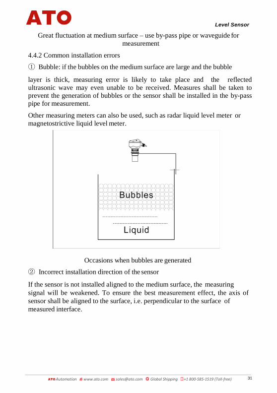
Great fluctuation at medium surface – use by-pass pipe or waveguide for measurement
4.4.2 Common installation errors
① Bubble: if the bubbles on the medium surface are large and the bubble
layer is thick, measuring error is likely to take place and the reflected ultrasonic wave may even unable to be received. Measures shall be taken to prevent the generation of bubbles or the sensor shall be installed in the by-pass pipe for measurement.
Other measuring meters can also be used, such as radar liquid level meter or magnetostrictive liquid level meter.
Occasions when bubbles are generated
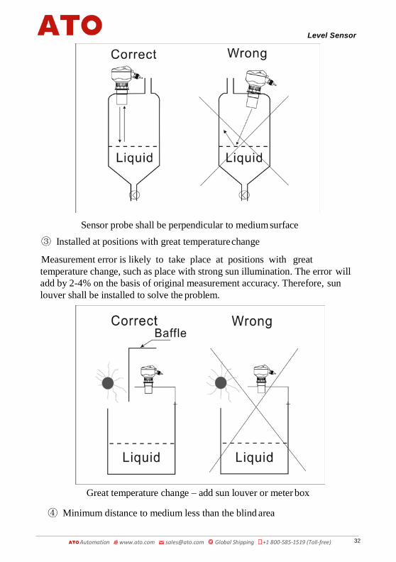
② Incorrect installation direction of the sensor
If the sensor is not installed aligned to the medium surface, the measuring signal will be weakened. To ensure the best measurement effect, the axis of sensor shall be aligned to the surface, i.e. perpendicular to the surface of measured interface.
31
Level Sensor
Automation www.ato.com [email protected] Global Shipping +1 800-585-1519 (Toll-free)
Sensor probe shall be perpendicular to medium surface
③ Installed at positions with great temperature change
Measurement error is likely to take place at positions with great temperature change, such as place with strong sun illumination. The error will add by 2-4% on the basis of original measurement accuracy. Therefore, sun louver shall be installed to solve the problem.
Great temperature change – add sun louver or meter box
④ Minimum distance to medium less than the blind area
32

Level Sensor
Automation www.ato.com [email protected] Global Shipping +1 800-585-1519 (Toll-free)
If the distance form probe to maximum level of the medium is less than the blind area of the meter, the measured values are wrong. ⑤ Sensor is too close to the container wall
If the sensor is installed too close to the container wall, strong false echo will be generated. The uneven inner surface of the container wall, attached medium, rivet, screw, reinforcing rib and joint weld on the container inner wall will lead to strong false echo which will be loaded on the effective echo signals. Therefore, the maximum distance shall be measured based on the requirements to keep the distance between the sensor and container wall, which is detailed as follows:
Maximum Measuring Range
Distance to Wall
Maximum Measuring Range
Distance to Wall
Maximum Measuring Range
Distance to Wall
5m 0.5m 10m 1.0m 15m 1.5m 20m 2.5m 30m 4m 40m 5m 50m 6m 60m 7.2m 70m 8.5m
Under worse measuring conditions, the distance between the sensor and the container wall shall be enlarged until no false echo occurs.
4.5 Electric wiring diagram
★ Prompt: make sure the connecting cable between the probe and meter body of separate-type ultrasonic level meter is long enough in advance. Connection with other cable for extension on site is not allowed as it will affect the signal transmission quality and strength. ★ During power line connection, AC power line shall not be connected to any other terminals except AC terminals. Otherwise, the meter circuit or components and parts will be burnt. ★ 485, 232 and 4-20ma output terminals shall not be short-circuited as short circuit will lead to burning of internal circuits.
The cables connecting the sensor and main equipment shall not be put in a trun king with any alternating current. If it can not be prevented, the cables of senso r shall be protected by a cable conduit to completely shield the electromagnetic interference caused by alternating current.
(1) Electric wiring diagram of standard single-probe separate-type ultrasonic level meter:
33

Level Sensor
Automation www.ato.com [email protected] Global Shipping +1 800-585-1519 (Toll-free)
◆ Diagram of standard single-channel separate-type wiring terminals
Wiring method:
Grounding: first make sure the grounding terminal of the meter is actually grounded and the meter does not share ground terminal with other equipment and then connect terminal 4.
Transducer: red wire: connected to Trans1 (transducer);
blue wire: Temp 1 + temperature sensor +
Black wire: GND (ground wire)
Current output: "current +" connected to mA1 +; "current -" connected to mA- /GND
Relay: RLlnA and RLnB are normally open;
To ensure the default state of relay is "normally open", RLlnA and RLnB shall be connected.
RlnA and RLnC are normal closed.
To ensure the default state of relay is "normally closed", RLlnA and RLnC shall be connected.
Power line: AC: connected to L and N
34
Level Sensor
Automation www.ato.com [email protected] Global Shipping +1 800-585-1519 (Toll-free)
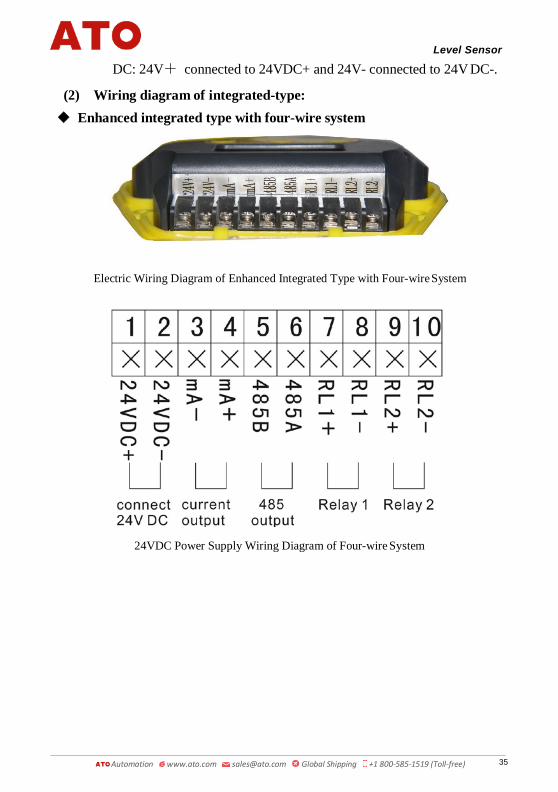
DC: 24V+ connected to 24VDC+ and 24V- connected to 24V DC-.
(2) Wiring diagram of integrated-type: ◆ Enhanced integrated type with four-wire system
Electric Wiring Diagram of Enhanced Integrated Type with Four-wire System
24VDC Power Supply Wiring Diagram of Four-wire System
35

Level Sensor
Automation www.ato.com [email protected] Global Shipping +1 800-585-1519 (Toll-free)
220VAC Power Supply Wiring Diagram of Four-wire System
◆ Enhanced integrated type with two-wire system
Electric Wiring Diagram of Two-wire System
Wiring Diagram of Two-wire System Ampere Meter Diagram of Two-wire System
36

Level Sensor
Automation www.ato.com [email protected] Global Shipping +1 800-585-1519 (Toll-free)
◆ Explosion-proof integrated type with four-wire system
Electric Wiring Diagram of Explosion-proof Integrated Type with Four-wire System
24VDC Power Supply Wiring Diagram of Four-wire System
220VAC Power Supply Wiring Diagram of Four-Wire System
37

Level Sensor
Automation www.ato.com [email protected] Global Shipping +1 800-585-1519 (Toll-free)
◆ Explosion-proof integrated type with two-wire system
24VDC Electric Wiring Diagram of Explosion-proof Integrated Type with Two-wire System
Wiring Diagram of Explosion-proof Connection of Explosion-proof
Integrated Type with Two-wire System Integrated Type with Two-wire System and Ampere Meter
V. Settings 5.1 Introduction of Interface of Operation Mode
Two working modes, operating and setting modes are provided for this series of ultrasonic level meter. After being powered on and initialized, the level meter will enter in the operating mode automatically, and start to measure data. Measurement at the time is under material level measurement mode and the relative output is 4~20mA. Output current is in direct proportion to the
38

Level Sensor
Automation www.ato.com [email protected] Global Shipping +1 800-585-1519 (Toll-free)
material level.
The interface of ultrasonic level meter under operating mode is as follows:
English Display Interface
VI. Menu Interface & Operating Instructions:The menu modes include expert setting mode and simply setting mode.
See the homepage for menu query table of simply setting mode.
See the appendix for menu query table of expert setting mode.
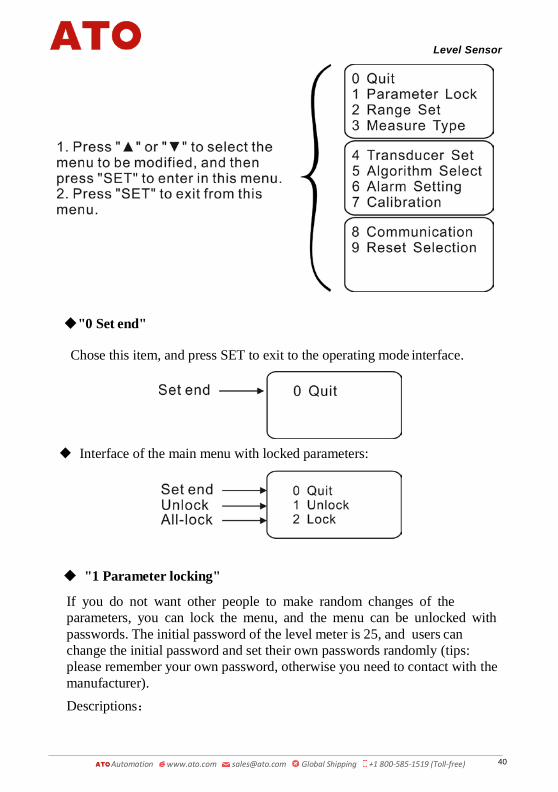
Menu interface of expert setting mode and operating instructions are shown below: ① Press SET in operating mode interface to enter in the "Mode selection
"main menu:
② Descriptions of the main menu items:
◆ Interface of the main menu with unlocked parameters:
39
Level Sensor
Automation www.ato.com [email protected] Global Shipping +1 800-585-1519 (Toll-free)
◆"0 Set end"
Chose this item, and press SET to exit to the operating mode interface.
◆ Interface of the main menu with locked parameters:
◆ "1 Parameter locking"
If you do not want other people to make random changes of the parameters, you can lock the menu, and the menu can be unlocked with passwords. The initial password of the level meter is 25, and users can change the initial password and set their own passwords randomly (tips: please remember your own password, otherwise you need to contact with the manufacturer). Descriptions:
40

Level Sensor
Automation www.ato.com [email protected] Global Shipping +1 800-585-1519 (Toll-free)
Unlock: unlock, and all parameters of the menu can be changed randomly.
All-lock: for the conditions, the changes can be made only after entering password.
★ If the parameters are locked, press SET and enter in the unlocking interface for parameter locking:
◆ "2 Range Set"
Set reference zero point, low range point, high range point and display unit.
1. Bottom Distance (Reference zero point): set the reference zero point of the level meter, and this value is only useful for material level measurement; the factory default is the maximum range.
2. Range-L (Low range point): set the output measurement value relative to 4mA of the level meter, and the factory default is 0.
3. Range-L (High range point): set the output measurement value relative to 20mA of the level meter, and the factory default is the maximum range.
4. Unit Selection (Display unit): there are three optional units, including m, cm and mm, wherein m stands for meter, cm for centimeter and mm for millimeter. The factory default is m.
41

Level Sensor
Automation www.ato.com [email protected] Global Shipping +1 800-585-1519 (Toll-free)
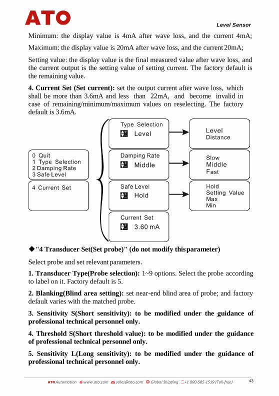
◆ "3 Measuring mode"
1. Type Selection (Select mode): there are two optional items, i.e. distance measurement and material level measurement.
Distance measurement: the display value is the distance from the probe to the surface measured;
Material level measurement: the display value is the distance from the bottom to liquid surface, i.e. liquid level height.
The factory default is material level measurement.
2. Damping Rate (Response rate): there are three optional items, i.e. slow speed, medium speed and fast speed.
Slow speed: the response rate is slow and measuring accuracy is high, not easy to be disturbed;
Medium speed: the parameters are between those for slow speed and fast speed;
Fast speed: the response rate is fast and measuring accuracy is low, very easy to be disturbed. The factory default is medium speed.
3.Safe Level (Safe material level): there are four optional items, i.e. remaining, minimum value, maximum value and setting value.
Remaining: the display value is the final measured value before wave loss, and the current is the corresponding value;
42
Level Sensor
Automation www.ato.com [email protected] Global Shipping +1 800-585-1519 (Toll-free)
Minimum: the display value is 4mA after wave loss, and the current 4mA;
Maximum: the display value is 20mA after wave loss, and the current 20mA;
Setting value: the display value is the final measured value after wave loss, and the current output is the setting value of setting current. The factory default is the remaining value.
4. Current Set (Set current): set the output current after wave loss, whichshall be more than 3.6mA and less than 22mA, and become invalid incase of remaining/minimum/maximum values on reselecting. The factorydefault is 3.6mA.
◆"4 Transducer Set(Set probe)" (do not modify this parameter)
Select probe and set relevant parameters.1. Transducer Type(Probe selection): 1~9 options. Select the probe accordingto label on it. Factory default is 5.
2. Blanking(Blind area setting): set near-end blind area of probe; and factorydefault varies with the matched probe.
3. Sensitivity S(Short sensitivity): to be modified under the guidance ofprofessional technical personnel only.
4. Threshold S(Short threshold value): to be modified under the guidanceof professional technical personnel only.
5. Sensitivity L(Long sensitivity): to be modified under the guidance ofprofessional technical personnel only.
43
Level Sensor
Automation www.ato.com [email protected] Global Shipping +1 800-585-1519 (Toll-free)
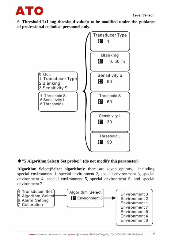
6. Threshold L(Long threshold value): to be modified under the guidanceof professional technical personnel only.
◆"5 Algorithm Select( Set probe)" (do not modify this parameter)
Algorithm Select(Select algorithm): there are seven options, including special environment 1, special environment 2, special environment 3, special environment 4, special environment 5, special environment 6, and special environment 7.
44

Level Sensor
Automation www.ato.com [email protected] Global Shipping +1 800-585-1519 (Toll-free)
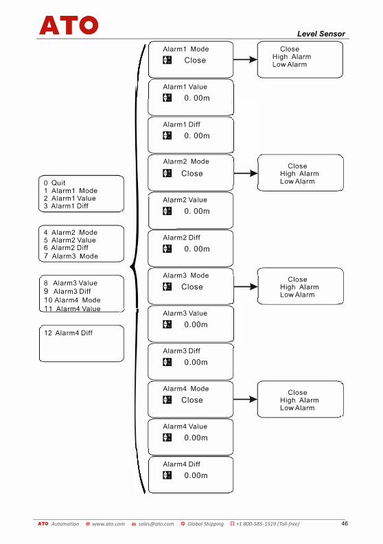
◆"6 Alarm setting" Set alarm relay.
Alarm 1 mode: closed mode, low-level alarm and high-level alarm are optional. Closed: relay 1 is out of service; low-level alarm: relay 1 sends low-level alarm signal; and high-level alarm: relay 1 sends high-level alarm signal. Factory default is closed mode.
Alarm 1 value: the unit is m and factory default is 0.
Alarm 1 Diff(Alarm 1 return difference): the unit is m, and after being triggered, the alarm can be canceled only after the measured value reaches the alarm value +/- alarm return difference. Factory default is 0.
Setting method of alarm 2/3/4 mode is the same as above.
Example: (how to use a relay to control startup/shutdown of water pump)
Through alarm return difference, one relay can control the whole working process of water pump from low level to high level.
For water drainage: when water level is below 1m, water pump stop draining; when water level rises to 5m, water pump start to drain water. Detailed settings are shown below:
Alarm 1 mode: high-level alarm. Alarm 1 value: 5.00m; alarm 1 return difference: 4.00m.
For water supply: when water level is below 1m, water pump start to feed water; when water level rises to 5m, water pump stop feeding water. Detailed settings are shown below:
Alarm 1 mode: low-level alarm. Alarm 1 value: 1.00m; alarm 1 return difference: 4.00m.
45
Alarm1 Mode Close
圈 Close High Alarm Low Alarm
Alarm1 Value
圈 0. OOm
Ala「m1 Diff
圈 0. OOm
Ala「m2 Mode
忏|Close
囤 Close High Alarm Low Ala「mO Quit
1 Alarm1 Mode 2 Alarm1 Value m2Val"' 3 Alarm1 Diff
L£' 0. OOm
4 Alarm2 Mode Alarm2 Diff 5 Alarm2 Value
6 Alarm2 Diff 圈 0. OOm7 Ala「『n3 Mode
Alarm3 Mode
忏|Close
围 Close High Alarm Low Alarm
8 Alarm3 Value 9 Alarm3 Diff 1 O Alarm4 Mode 11 Alarm4 Value / . Alarm3 Value
圈 O.OOm 12 Ala「m4 Diff
Alarm3 Diff
囤 O.OOm
Alarm4 Mode Close 囤 Close High Alarm
Low Alarm
Alarm4 Value
圈 。.OOm
Alarm4 Diff
围 O.OOm
Automation www.ato.com [email protected] Global Shipping +1 800-585-1519 (Toll-free)
Level Sensor
46

Level Sensor
Automation www.ato.com [email protected] Global Shipping +1 800-585-1519 (Toll-free)
◆"7 Calibration (Parameter correction)" (do not modify this parameter)
Carry out correction of range, sound velocity, current output and reference level.
1. Range Adjust (Range correction): after input of the actual value,the system will correct the range automatically. Factory default is themeasured value.
2. Sound Adjust (Sound velocity correction): after input of the actualvalue, the system will correct the sound velocity automatically, appliedwhen gas composition is not air. For example, propagation velocity of soundis different in places with gasoline, acetone, ethyl alcohol and othervolatile gas, so correction is necessary.
3. 4mA Adjust (4mA correction): keep modifying the value until theactual output current reaches 4mA. Factory default is 3100.
When multimeter is connected to 4-20ma positive pole in series, this number shall be increased or decreased by 1 so that 4mA correction can be realized.
4. 20mA Adjust (20mA correction): keep modifying the value until the actualoutput current reaches 20mA. Factory default is 7200.
5. Voltage (Reference level): input the measured voltage at relevant testpoint.Factory default is 5.00.
47

Level Sensor
Automation www.ato.com [email protected] Global Shipping +1 800-585-1519 (Toll-free)
◆ "8 Communication setting"
1. Address (Communication address): select communication address; and thedefault is 1.
2. Baud rate: select communication frequency among 2400, 4800, 9600 and19200; and the default is 9600.
3. Working Mode (Operating mode): select communication operating modebetween "Automatic report mode" and "Inquiry mode"; and the default is"Automatic report mode".
48

Level Sensor
Automation www.ato.com [email protected] Global Shipping +1 800-585-1519 (Toll-free)
◆ "9 Reset options"
1.Factory reset: Yes: restore factory settings so that setting error can be resolved.
No: exit. Factory default is No.
2.System reset: Yes: restore system settings. No: exit. Factory default is No. (Do not modify this item.)
49

Level Sensor
Automation www.ato.com [email protected] Global Shipping +1 800-585-1519 (Toll-free)
VII. Faults and HandlingIf all wirings are normal through inspection in case of a fault, after ultrasonic level meter is grounded, you can keep pressing "▲", then press "SET" to show echo menu, take a photo of the echo menu and send it to us via MMS or picture. By this way, we can determine the possible electromagnetic interference, false echo, situation of entering a blind area, no echo signal received and other faults.
Faults Causes Handling
Level meter does not work.
Power supply is not well connected.
Inspect power line.
Level meter does not 1.Power supply is not 1.Inspect power line.display data. well connected.
2.Wiring between LCD 2.Inspect the wiring and connect itand mainboard falls off again.or comes loose.3.The LCD is damaged. 3.Maintain it in the factory.
Level meter works but 1.The measured area is 1.Replace the level meter with a levelthere is no change of beyond the measuring meter with greater measuring range.
trumpet icon ( ) range of level meter.
on the LCD, which means that the system is in wave loss state.
2.The measured mediumhas strong disturbance,vibration or heavy dust.
2.The meter will restore the normalmeasurement automatically after themeasured medium gets back to calm.
3.There are strong 3.Check surrounding environment andinterference sources realize good electromagneticaround such as shielding. Do not share one powerfrequency converter and supply with frequency converter andmotor. motor, and make it grounded reliably.
4.The probe is not 4.Reinstall probe and make italigned to the measured perpendicular to liquid surface.surface.
5.There are redundant 5.Select an appropriate position forobjects in the measured installation and prevent an interferingspace, such as support object.rod and feed opening.
6.The liquid level is in a 6.Raise the installation position ofblind area. probe.
7.The measured medium 7.Check whether the medium isis soft powder or there is powder. If so, consult thefoam on liquid surface. manufacturer.
50

Level Sensor
Automation www.ato.com [email protected] Global Shipping +1 800-585-1519 (Toll-free)
Operating Instructions for Simple Settings of Ultrasonic Level Difference Sensor
The ultrasonic level difference meter produced by our company applies all Chinese menus for simple setting. It can meet different requirements of customers. Normally, after the ultrasonic level difference meter is installed as per the installation requirements of the instructions, it can be used after the following several parameters are set.
Simple operating instructions: 1. Button functionsThere are three buttons on the panel, via which themeter can be adjusted. The measured values are displayedon the LCD screen after the adjustment.
KEY KEY
Enter menu item Move cursor
Confirm menu item Choose menu item
Confirm parameter modification Modify parameter
2. After power-on display of the meter, long press the set button (SET) for2s to enter in the main menu.3 . Input #1 probe height value to "reference zero point 1" which is arranged in the structural chart of the menu as shown in attached table (probe height is the distance from probe emitting surface to tank bottom or pool bottom). 4 . Input #2 probe height value to "reference zero point 2" which is arranged in the structural chart of the menu as shown in attached table 1. 5. Set "4mA corresponding difference value" and "20mA correspondingdifference value"
4mA corresponding difference value: output 4mA when the difference value is equal to the set value.
20mA corresponding difference value: output 20mA when the difference value is equal to the set value.
SET
51

Level Sensor
Automation www.ato.com [email protected] Global Shipping +1 800-585-1519 (Toll-free)
The "4mA corresponding difference value" and "20mA corresponding difference value" are situated in the structural chart of the menu as shown in attached table.
I. Purpose Ultrasonic level difference meter (material level, liquid level) is used to measure the liquid level or material level difference between two containers.
It is most commonly used to measure the water level difference in front and rear of coarse and fine racks at the water inlet of sewage treatment plant, calculate the water level difference and start up the back dragging cleaner to take out rubbish.
52

Level Sensor
Automation www.ato.com [email protected] Global Shipping +1 800-585-1519 (Toll-free)
II. Main Technical Parameters
Function Split type
Normal measuring range
5m, 10m, 15m, 20m
Special measuring range
30m, 40m, 50m, 60m
Measuring accuracy 0.5%-1.0%
Resolution ratio 3mm or 0.1% (whichever is greater)
Display 12864 dot-matrix Chinese font LCD
Analog output 2nd-circuit 4~20mA/ 510Ω load
Relay output 4th-circuit AC 250V/ 8A or DC 30V/ 5A state programmable (optional)
Power supply 220V AC+15% 50Hz or 24VDC 120m Optional
Ambient temperature
Display instrument (transmitter): -20~+60ºC Probe (sensor): -20~+80℃
Communication 485 communication (optional)
IP grade Display instrument: IP65, probe: IP68
Probe cable Standard 10m, it can reach 200 maximum (it is required to shield all electromagnetic interference)
Probe installation Subject to the measuring range and type of probe
53

Level Sensor
Automation www.ato.com [email protected] Global Shipping +1 800-585-1519 (Toll-free)
III. Electric Wiring Diagram ◆ Electric wiring diagram of ultrasonic level difference meter and wiring terminal diagram:
Wiring method:
Grounding: first make sure the grounding terminal of the meter is actually grounded and the meter does not share ground terminal with other equipment and then connect terminal 4.
Transducer: red line: connected to Trans_n transducer n; blue line: Temp n + temperature sensor +
Black wire: GND (ground wire)
For single probe, n =1; for double probes, n = 1,2
Current: current + connected to mA n+; current - connected to mA n- /GND
For single probe, n =1; for double probes, n = 1,2
Relay: RLlnA and RLnB are normally open; RLnA and RLnC are normally closed
For single probe, n =1.2; for double probes, n= 1,2,3,4
Power line: AC: connected to L and N
54

Level Sensor
Automation www.ato.com [email protected] Global Shipping +1 800-585-1519 (Toll-free)
Remarks:
DC: 24V+ connected to 24VDC+; GND connected to 24V DC-
① Relay 1 is used for probe 1 alarm, relay 2 is used for probe 2 alarm, relay 3 and relay 4 are used for difference value alarm.
② ★ mA1+ and mA- output current difference value. By default, mA2+ and mA- output probe 2 current and they can also output probe 1 current (select in "9 work mode" – "2 mAOut 2 output"). ★ Under the work mode of two levels, mA 1+ and mA- output probe 1
current, mA2+ and mA- output probe 2 current.
55

Level Sensor
Automation www.ato.com [email protected] Global Shipping +1 800-585-1519 (Toll-free)
Warranty Card Receipt of Ultrasonic Level Gauge and Ultrasonic Level Difference Meter
User name Contact address Contact person Tel. Product model Product No. Date of acceptance Installer
Explanation for Warranty Card of Ultrasonic Level Gauge
Product model Product No. Date of acceptance Installer
Warranty Policy:
1. Please show the warranty card for maintenance. You will enjoy the promised free warranty service for any faults occurring during normal operation in the warranty period. 2. Warranty period: 12 months from date of acceptance.
The following situations are beyond warranty coverage: 1. The whole or parts of the product are out of the free warranty period. 2. Hardware failures are caused because the use environment is not complied with the product use requirements. 3. Faults or damages are found because unfavorable power supply or foreign matters enter into the device. 4. Failures occur due to offending the use method and precaution specified in the operation manual. 5. Failures are caused because of force majeure like lightning, and water and fire disasters. 6. Failures or damages are fund due to teardown repair without permission, refit in excess of authority or misuses.
56

Level Sensor
Automation www.ato.com [email protected] Global Shipping +1 800-585-1519 (Toll-free)
Limitations: 1. Please keep the warranty card in a safe place and use it as your only warrantyvoucher. It will not be replaced if lost.
The company reserves the rights to the explanation of the warranty card, and the company also reserves the right to make changes to the warranty card contents without further notice.
57
Level Sensor
Automation www.ato.com [email protected] Global Shipping +1 800-585-1519 (Toll-free)
How to judge the fault causes at site according to echo pattern
The ultrasonic level gauge has a function that it can show the ultrasonic wave form reflected from the site, so that the fault causes at site can be roughly judged according to the shape of echo. Now, please allow me to explain it in details. Enter echo pattern: press the ↑ button and hold on, and then press the Set button and hold on for 3s, an echo pattern will appear.
Exit echo pattern: press the ↓ button and hold on, and then press the Set button and hold on for 3s, the echo pattern will disappear.
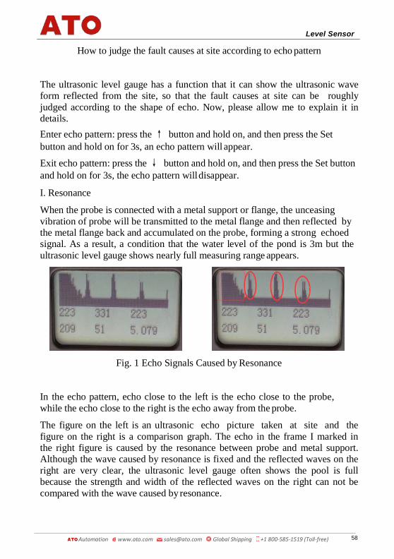
I. Resonance
When the probe is connected with a metal support or flange, the unceasing vibration of probe will be transmitted to the metal flange and then reflected by the metal flange back and accumulated on the probe, forming a strong echoed signal. As a result, a condition that the water level of the pond is 3m but the ultrasonic level gauge shows nearly full measuring range appears.
Fig. 1 Echo Signals Caused by Resonance
In the echo pattern, echo close to the left is the echo close to the probe, while the echo close to the right is the echo away from the probe.
The figure on the left is an ultrasonic echo picture taken at site and the figure on the right is a comparison graph. The echo in the frame I marked in the right figure is caused by the resonance between probe and metal support. Although the wave caused by resonance is fixed and the reflected waves on the right are very clear, the ultrasonic level gauge often shows the pool is full because the strength and width of the reflected waves on the right can not be compared with the wave caused by resonance.
58

Level Sensor
Automation www.ato.com [email protected] Global Shipping +1 800-585-1519 (Toll-free)
Fig. 2 Echo Signals after Resonance Problem Solved
After the resonance problem is solved, the echo close to the left is obviously narrower than that shown in Fig. 1 and the real echo can be recognized by the ultrasonic level gauge then.
II. Liquid enters the blind area of ultrasonic level gauge
Fig. 3 Echo Pattern after Liquid Enters Blind Area
The ultrasonic level gauge has a blind area at the position near the emitting surface of probe. The blind area will increase with the increase of effective measuring distance. For example, the ultrasonic level gauge with a measuring range of 5m has a 0.50m blind area at 20℃.
The echo enclosed by the red frame in figure above is the high-intensity echo caused by blind area and the echo enclosed by red circle is normal echo signal. Due to strong echo caused by blind area, the real echo signals on the right are covered and the measured water level data may be any values. Seeing carefully, you may find that the echo in blind area is similar to the echo caused by resonance in Fig. 1.
After we raise the installation position of probe to make the distance from the highest water level to the emitting surface of probe be greater than 0.50 (blind area), we find that the echo close to probe on the left changes.
59

Level Sensor
Automation www.ato.com [email protected] Global Shipping +1 800-585-1519 (Toll-free)
Fig. 4 Echo Pattern after Probe Lifting
III. Electromagnetic interference
Electromagnetic interference at site mainly comes from frequency converter, motor and centrifuge. These interferences are mostly transmitted through power grid. If the power supply system of a plant has one frequency converter, the entire power grid will be polluted. Let’s use see the normal echo pattern:
Fig. 5 Normal Echoed Signals
The two figures above are normal echo patterns. The downmost base line (the cross bar from the left to right) is about 4mm high. It is clear and same high from the left to right, without burrs. Signals in the red circle are ultrasonic echoed signals and they are very obvious.
Fig. 6 Echo Pattern under Electromagnetic Interference
The left figure above is the original figure. On the right figure, I enclosed
60

Level Sensor
Automation www.ato.com [email protected] Global Shipping +1 800-585-1519 (Toll-free)
the burrs with a red circle and they are caused by electromagnetic interference. In the echo pattern, there is no obvious echo and the burrs above the base line just show electromagnetic interference. The three figures in the first row and the first two figures in the second row below the base line are all 0, meaning that the echo is covered by the wave from probe.
Fig. 7 Echo Pattern under Interference of Frequency Converter
The left figure above is the original figure. On the right figure, I enclosed the wave crests with red circles. The wave crests enclosed by the red circles are uniformly spaced based on certain laws and they are electromagnetic interferences caused by typical frequency converter. The figures in the two rows below the base line are not 0 but they don't make sense as they are caused by electromagnetic interference.
Fig. 8 Echo Pattern under Interference of Frequency Converter
The left figure above is the original figure. On the right figure, I enclosed the real echo with red circles and enclosed the interference waveform with red frame. The interference waveform is quite higher than the real echo and it can not recognized by the ultrasonic wave.
61

Level Sensor
Automation www.ato.com [email protected] Global Shipping +1 800-585-1519 (Toll-free)
Fig. 9 Echo Pattern under Interference of Frequency Converter
Fig. 6 is interesting. The echo enclosed by circle is real echo and the echo enclosed by frame is the interference wave of frequency converter. Although there is interference of frequency converter, the data measured at site is correct as the echoed signal intensity on water surface is obviously stronger than the interference signal of frequency converter.
Fig. 10 Echo Pattern under Strong Interference
The left figure above is the echo pattern under strong interference and the figure shows high interference waves from left to right. Under the condition, ground connection can not solve all problems. At this time, we should judge the interference is from the power supply or the air.
If the electromagnetic interference is from air, a metal instrument box should be made for the instrument and the instrument box should be grounded.
Therefore, if the electromagnetic interference is from cable, especially for the ultrasonic level gauge applying two-wire system frequency used, a passive signal isolator should be used to solve the interference problem.
For meter applying four-wire system, isolated power supply should be applied and signal isolator should be applied at 4-20ma output part.
IV. Effects of connecting pipe to measurement
62

Level Sensor
Automation www.ato.com [email protected] Global Shipping +1 800-585-1519 (Toll-free)
If the probe of ultrasonic level gauge is in a connecting pipe, some problems may be caused as the connecting pipe may amplify the signals. Generally, the height and diameter of the connecting pipe are in proportion, i.e. 5:3. If the height is 200mm, the inner diameter of connecting pipe will be above 120mm.
Fig. 11 Echo when Probe is in Connecting Pipe
In the figure above, the base line of echo pattern is very wide, which is caused by signal amplification by connecting pipe. The echo enclosed by circle is real echo while the part enclosed by frame is wide base line.
Fig. 12 Echo when Probe is Out of Connecting Pipe
After the ultrasonic level gauge is taken out of the connecting pipe, the base line narrows obviously and becomes normal. The echo in circle will be much higher than the base line.
63