ultrasonic flow transmitter, 1 fundamentals of the ... · ultrasonic flow transmitter of the...
TRANSCRIPT

© Festo Didactic 85997-00 1
Learn the working principle of ultrasonic flowmeters, familiarize yourself with the ultrasonic flow transmitter of the Instrumentation and Process Control Training System, and learn how to commission it.
The Discussion of this exercise covers the following points:
Introduction
How an ultrasonic flowmeter worksTransit-time flowmeters. Frequency-difference measurement. Reynolds-number correction. Construction and installation. One, two, and four traverses.
Characteristics of ultrasonic flowmetersAdvantages and limitations. Industrial applications.
Description of the supplied ultrasonic flowmeterSummary of technical specifications.
Installing the ultrasonic flowmeterInstallation procedure.
Calibration
Introduction
The invention of the ultrasonic flowmeter can be traced back to 1963 when Tokyo Keiki, a Japanese company, first commercialized this type of flowmeter. Almost a decade later, Controlotron (now part of Siemens) was the first American company to manufacture ultrasonic flowmeters. It was not until recently that manufacturers were able to overcome the main challenges of ultrasonic flow measurement and make affordable and reliable ultrasonic flowmeters.
Ultrasonic flowmeters are available in two types: transit-time measurement and Doppler effect. Transit-time flowmeters measure the fluid velocity by comparing the downstream and upstream traveling times; the time difference between the two is proportional to the average fluid velocity. Doppler effect flowmeters measure the fluid velocity from the ultrasonic waves reflected back from bubbles or particles in suspension in the liquid. The disadvantage of this method is that the ultrasonic waves need something to reflect upon; hence, this flow measurement method is not suitable for clean water. In the following section, we will concentrate on the transit-time flow measurement method, which is ideal for acoustically transparent liquids.
How an ultrasonic flowmeter works
Below is a description of the time-transit method, which is one of the two measurement methods behind ultrasonic flowmeters. The different setups for the
Fundamentals of the Ultrasonic Flowmeter
Exercise 1
EXERCISE OBJECTIVE
DISCUSSION OUTLINE
DISCUSSION

Exercise 1 – Fundamentals of the Ultrasonic Flowmeter Discussion
2 © Festo Didactic 85997-00
sensors and the electronic corrections available for most ultrasonic flow transmitters are also discussed.
Transit-time flowmeters
The basic principle behind transit-time flowmeters is simple: two ultrasonic energy pulses traverse diagonally through a pipe in opposite directions, with one pulse transmitted downstream (with the flow) and one pulse transmitted upstream (against the flow), as shown in Figure 1. The flowmeter measures the transit-time for both pulses, that is, the time it takes for the pulses to get from one sensor to the other. The flowmeter then computes the average velocity of the fluid from the difference between the two transit-times.
Figure 1. Transit-time flowmeter principle.
To operate correctly, transit-time ultrasonic flowmeters require that the process fluid is transparent to ultrasonic waves and devoid of air bubbles or particles that can reflect or attenuate ultrasonic waves.
A sound wave traveling in a moving fluid tends to be carried along with the flow. Therefore, an ultrasonic pulse traveling downstream travels faster than a pulse traveling upstream. Figure 2 shows that the flow direction of the fluid (moving at an average velocity ) is at an angle with the ultrasonic signal path. Depending on whether the ultrasonic signal is travelling upstream (Figure 2a) or downstream (Figure 2b), the portion of the fluid velocity parallel to the ultrasonic signal path is added or subtracted from the sound velocity.
Figure 2. Transit time for the a) upstream signal and b) downstream signal.
Flow
Upstream signal
(a) (b)
Transducer B
Transducer A Downstream signal

Exercise 1 – Fundamentals of the Ultrasonic Flowmeter Discussion
© Festo Didactic 85997-00 3
Figure 3 shows how the velocity of the fluid influences the velocity of the ultrasonic pulse. For the ultrasonic pulse traveling downstream (Figure 3a), the velocity of the fluid contributes positively to the overall speed of the pulse. Since the two
transducers are at an angle , the contribution of fluid velocity to the ultrasonic pulse velocity is . For the ultrasonic pulse travelling upstream (Figure 3b), the
velocity of the fluid reduces the overall speed of the pulse by .
Note that the vectors are not to scale. The length of is greatly exaggerated so
that the principle can be illustrated clearly. In general, the fluid velocity is much smaller than the speed of sound .
Figure 3. Contribution of fluid velocity to the speed of ultrasound pulse.
Knowing this, it is easy to calculate the time it takes for an ultrasonic pulse to travel downstream for the distance between transducer A and transducer B. The pulse
transit-time from A to B is simply the distance divided by the pulse velocity. It is expressed as follows:
(1)
where is the transit time for the ultrasonic pulse to travel the distance is the distance between the two transducers is the speed of sound is the average fluid velocity
is the angle between the ultrasonic pulse path and the pipe axis
An ultrasonic pulse travelling upstream is slowed by the fluid flow. The transit time from transducer B to transducer A can be calculated using an equation similar to the one used for a downstream pulse, except that the contribution of the fluid flow must be subtracted from the sound velocity instead of added. Equation (2) gives the transit time for an ultrasonic pulse traveling upstream.
(2)
(a) (b)

Exercise 1 – Fundamentals of the Ultrasonic Flowmeter Discussion
4 © Festo Didactic 85997-00
Combining Equation (1) and Equation (2) allows the time difference between the two transit times to be expressed as follows:
(3)
This relation can be simplified further as detailed below:
Since , we have ; therefore can be neglected
compared to and the time difference can be approximated as:
(4)
Using Equation (4) we find that the average velocity of the fluid is:
(5)
Following steps similar to those presented above, it can be shown that the average transit-time is:
(6)
Thus, Equation (5) can be simplified as:
(7)
An important corollary of Equation (7) is that the measure of the fluid velocity using an ultrasonic flowmeter is independent of the speed of sound. This means that measurements made with an ultrasonic flowmeter are independent of the fluid temperature and pressure, which is an important advantage for several applications.
Frequency-difference measurement
Another way to analyze what is going on in an ultrasonic flowmeter is to look at the frequency difference between the upstream and downstream pulses. The

Exercise 1 – Fundamentals of the Ultrasonic Flowmeter Discussion
© Festo Didactic 85997-00 5
frequency for each of the two pulses is the reciprocal of their respective transit time. That is:
and (8)
The frequency difference is expressed in Equation (9).
(9)
Thus, the average velocity of the process fluid is:
(10)
Both Equation (7) and Equation (10) are independent of temperature, pressure, density, and viscosity. Once the average velocity of the process fluid is known, the flow rate can be easily calculated using the cross-sectional area of the pipe:
(11)
where is the flow rate
is the average fluid velocity is the cross-sectional area of the pipe
Reynolds-number correction
The distribution of the local velocities varies according to the average velocity of the fluid in a pipe. The form that the distribution of the velocities takes is called the flow profile. Figure 4 shows a laminar profile and a turbulent flow profile, which are the two main types of flow profiles for a fluid in a pipe. A turbulent flow (Figure 4a) has an almost flat velocity profile while a laminar flow (Figure 4b) has a velocity profile with a “bump” since the distribution of the velocities is not uniform. Therefore, with a laminar profile, the ultrasonic pulse velocity varies along its path between the two transducers, depending on the local fluid velocity.
Laminar flow occurs at a low flow rate. To determine if a flow is turbulent or laminar, the Reynolds number must be calculated. If the Reynolds number is greater than 4000, the flow is turbulent. A Reynolds number below 4000 means the flow is either transitional (a mix between laminar and turbulent) or laminar (below 2000).

Exercise 1 – Fundamentals of the Ultrasonic Flowmeter Discussion
6 © Festo Didactic 85997-00
Figure 4. Shape of the different velocity profiles.
To tackle the problem caused by the variation of the flow profile, many ultrasonic flowmeters include a Reynolds-number correction mechanism. This usually involves multiple ultrasonic measurement beams coupled with an algorithm that matches the measurements with a flow profile to make the required corrections for determining the average flow rate of the fluid.
c For details on the calculation of the Reynolds number or on the different types of flows, refer to the Measurement manual.
Construction and installation
The transducers of an ultrasonic flowmeter are either housed in a pipe section with flanged ends or installed on a clamp-on system, allowing them to fit on a wide range of pipe diameters.
The ultrasonic pulses are generated and detected by the transducers using piezoelectric crystals. Piezoelectric material, mainly crystals and some ceramics, has the peculiar ability to generate an electric signal when subjected to a mechanical stress such as vibration. The beauty of piezoelectricity is that it also works the other way around! That is, if an electric signal is applied to a piezoelectric material, it responds by vibrating at its resonant frequency.
For small pipe diameters, the transit time is short since the traveled distance between the two transducers is small. Too small a travel distance produces inaccurate and sometimes unusable signals. Using one of the multiple traverses installations described below can correct this problem.
One, two, and four traverses
For small pipelines, it is possible to amplify the time difference between the two transit times by increasing the distance the ultrasonic pulse has to cross. This is done by making the pulse bounce one or more times on the pipe walls. Figure 5a shows a one traverse installation where the signal goes directly from one transducer to the other, Figure 5b shows a two traverses installation where the signal bounces once on the pipe walls before being detected, and finally, Figure 5c shows a four traverses installation where the signal bounce three times and the crossed distance is multiplied by four compared to a one traverse installation.
(b)
(a)

Exercise 1 – Fundamentals of the Ultrasonic Flowmeter Discussion
© Festo Didactic 85997-00 7
Figure 5. One, two, and four traverses.
Characteristics of ultrasonic flowmeters
Ultrasonic flowmeters are useful for clean water applications. They are particularly useful for applications where the flowmeter cannot come into contact with the process fluid, either because it is installed on an existing installation or because it can contaminate or disturb the process fluid.
Advantages and limitations
Below is a list of some of the advantages and limitations of time-transit flowmeters. Some of these advantages and limitations, but not all, also apply to Doppler flowmeters which also use ultrasound to measure flow rate.
Can be used on large diameter pipes
Cause no obstruction or pressure drop
Not affected by changes in the liquid temperature, viscosity, density, or
pressure
Easy to install using clamp-on sensors
Can be installed on an existing installation
Can measure null, laminar, transitional, and turbulent flows
45°
(a)
(b)
(c)

Exercise 1 – Fundamentals of the Ultrasonic Flowmeter Discussion
8 © Festo Didactic 85997-00
Can measure nonconductive fluids
No moving parts
Long operating life
No risk of process contamination
Work well for nonconductive fluids or ultra-pure water
Notwithstanding these numerous advantages, ultrasonic flowmeters using the time-transit method have the following limitations and disadvantages:
Subject to interference from the pipe wall
Cannot be used for dirty or particulate-laden fluids
Bubbles in the fluid or air between the fluid and the pipe wall affect
accuracy and repeatability
The fluid must be acoustically transparent
The signal can be attenuated by concrete, fiberglass, or plastic-lined pipes
Accuracy depends on the flow profile
Expensive
Can be used only in limited applications
Build-up in pipes can cause reading errors
Industrial applications
The limitations of ultrasonic flowmeters restrict their use to a small range of applications. Nonetheless, they are extremely useful in this well-defined niche. Some of the applications where ultrasonic flowmeters are likely to be used are listed below:
Clean fluid measurement (water, natural gas, liquefied gases)
Clean water in water treatment plants
Hot and cold water supply in commercial or public buildings
Pure and ultra-pure water in semiconductor, pharmaceutical, and food
industries
Acid flow measurement in the chemical industry
Acoustically transparent crude oil
Cryogenic liquids
Description of the supplied ultrasonic flowmeter
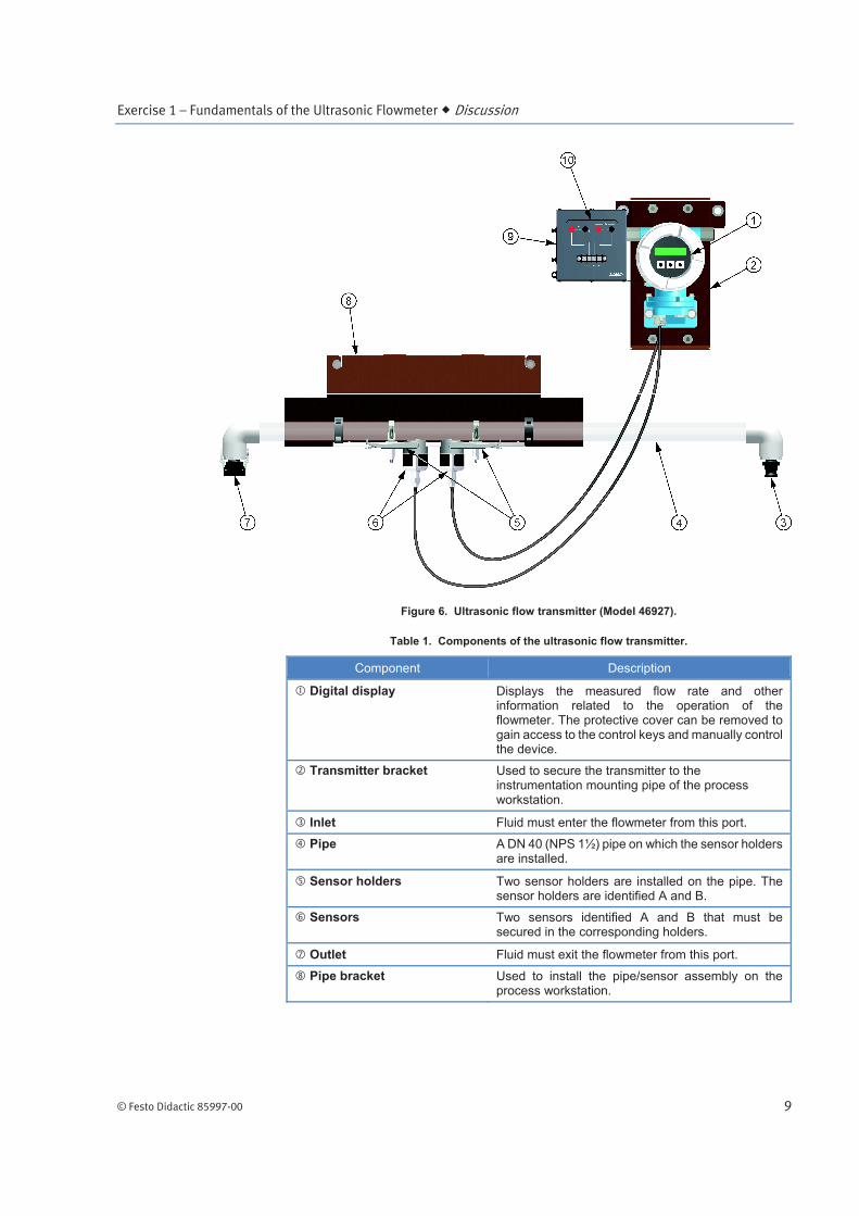
The ultrasonic flow transmitter (Model 46927) is shown in Figure 6. It consists of a transmitter with two sensors that can be mounted on a transparent pipe using the preinstalled sensor holders affixed with tensioning bands. The transparent pipe is installed on a bracket for mounting on the process workstation, while the bracket of the transmitter allows it to be secured on the instrumentation mounting pipe. Table 1 describes the main components of the ultrasonic flow transmitter.
Exercise 1 – Fundamentals of the Ultrasonic Flowmeter Discussion
© Festo Didactic 85997-00 9
Figure 6. Ultrasonic flow transmitter (Model 46927).
Table 1. Components of the ultrasonic flow transmitter.
Component Description
Digital display Displays the measured flow rate and other information related to the operation of the flowmeter. The protective cover can be removed to gain access to the control keys and manually control the device.
Transmitter bracket Used to secure the transmitter to the instrumentation mounting pipe of the process workstation.
Inlet Fluid must enter the flowmeter from this port.
Pipe A DN 40 (NPS 1½) pipe on which the sensor holders are installed.
Sensor holders Two sensor holders are installed on the pipe. The sensor holders are identified A and B.
Sensors Two sensors identified A and B that must be secured in the corresponding holders.
Outlet Fluid must exit the flowmeter from this port.
Pipe bracket Used to install the pipe/sensor assembly on the process workstation.

Exercise 1 – Fundamentals of the Ultrasonic Flowmeter Discussion
10 © Festo Didactic 85997-00
Component Description
Fault panel Contains one switch used to simulate a fault with the apparatus.
24 V dc input / Analog output
Power input for the flowmeter. Used to energize the ultrasonic flowmeter with a 24 V dc signal. The analog output provides a 4-20 mA signal proportional to the measured flow rate. A HART communication signal can be sent from the output.
The display can be used to configure several parameters and to read the flow rate directly. The function of each button is described below:
go backward in a menu or modify a value
go forward in a menu or modify a value
select an item from a menu or store an entry
ESC press the + and – buttons simultaneously to return to the previous menu or display
Summary of technical specifications
Some technical specifications are summarized in this section. For further details, please refer to the documentation provided with the system.
Device name Prosonic 91
Measured variables Flow velocity
Power supply 24 V dc
Communication protocols HART
Pipe diameter 3.8 cm (1.5 in)
Measuring range 0 m/s to 15 m/s (0 ft/s to 50 ft/s)
Flow accuracy ±2% of reading or ±7.5 mm/s (0.3 in/s) of maximum full scale value
Temperature of the process -20°C to 80°C (-4°F to 176°F)
Installing the ultrasonic flowmeter
The ultrasonic flowmeter is heavy and bulky. Use proper techniques to lift it and request
help whenever necessary. Always wear safety shoes when working with this equipment and
make sure it is properly secured to the workstation.

Exercise 1 – Fundamentals of the Ultrasonic Flowmeter Discussion
© Festo Didactic 85997-00 11
The following equipment and tools are required to install the ultrasonic flowmeter on the instrumentation workstation:
Ultrasonic flowmeter
Spring nuts and bolts for fixation to the support strut
Ratchet with a ½ in. socket or an equivalent wrench
Mounting rail
Adjustable wrench
Screw driver
Coupling fluid
Installation procedure
The ultrasonic flowmeter has two main components, the transmitter and the pipe/sensors assembly. The transmitter is designed to be installed on the instrumentation mounting pipe of the process workstation, while the pipe with the sensors must be installed horizontally on one of the struts of the process workstation.
The ultrasonic flowmeter is a delicate instrument and it must be carefully installed as described in the procedure below. Even if the sensor holders are preinstalled, you may have to remove them for maintenance or pedagogical reasons. This procedure describes how to install the ultrasonic transmitter, including how to correctly install the sensor holders.
1. Secure the pipe bracket on the process workstation and the transmitter bracket on the instrumentation mounting pipe.
2. If the tensioning bands are not installed on the pipe, install them as shown in Figure 7 without tightening them.
Figure 7. Install the tensioning bands.
3. Using a screw driver, tighten the tensioning band A, which is the closest to the inlet (Figure 8).

Exercise 1 – Fundamentals of the Ultrasonic Flowmeter Discussion
12 © Festo Didactic 85997-00
Figure 8. Tighten the tensioning band A.
4. Using the mounting rail, adjust the distance between the two tensioning bands so that one of the threaded studs is at position I and the other at position 27, as shown in Figure 9.
Figure 9. Use position I27 on the mounting rail to adjust the distance.
5. Once the studs are correctly spaced, use a screw driver to tighten the second tensioning band. To ensure both studs are correctly spaced, do not remove the mounting rail before both tensioning bands are tightened.
6. Install the sensor holders on the pipe using the threaded studs. Tighten the nuts using an adjustable wrench as shown in Figure 10.
Figure 10. Tighten the nuts.

Exercise 1 – Fundamentals of the Ultrasonic Flowmeter Discussion
© Festo Didactic 85997-00 13
7. Once both sensor holders are installed, your setup should look as shown in Figure 11.
Figure 11. Both sensor holders correctly installed.
8. Coat the surface of each of the sensor housings with approximately 0.5 mm (0.02 in) of coupling fluid as shown in Figure 12.
Figure 12. Coat the surface of the sensor housings with coupling fluid.
9. Press each of the sensor housings into position until they are locked in their respective holders. You will hear a click (Figure 13).
Figure 13. Press the sensor housings into position.
10. Once both sensor housings are installed, your setup should look as shown in Figure 14.
Coat with coupling fluid

Exercise 1 – Fundamentals of the Ultrasonic Flowmeter Discussion
14 © Festo Didactic 85997-00
Figure 14. Installed sensor housings.
11. Insert each sensor cable into its housing. Make sure to insert the A cable into the housing installed on the holder labeled A on the pipe (Figure 15) and the B cable into the housing on the holder labeled B (Figure 16).
Figure 15. Insert sensor cables.
Figure 16. Insert the cables in the housings.
12. Once the sensor holders, the sensor housings, and the sensor cables are properly installed, the pipe with the installed components should look as shown in Figure 17.

Exercise 1 – Fundamentals of the Ultrasonic Flowmeter Procedure Outline
© Festo Didactic 85997-00 15
Figure 17. Sensors installed on the pipe.
13. The ultrasonic flow transmitter is now ready to be configured as described in the Procedure section below.
Calibration
The ultrasonic flowmeter is calibrated by the manufacturer at the factory and should not require further calibration. Nevertheless, some calibration parameters are available, but it is not recommended to modify any of them. Please refer to the manufacturer documentation for details.
The Procedure is divided into the following sections:
Set up and connections
Commissioning the ultrasonic flow transmitterEnabling programming mode (access code). Changing the transmitter units. Commissioning.
Using the ultrasonic flow transmitter
Set up and connections
1. Connect the equipment according to the piping and instrumentation diagram (P&ID) shown in Figure 18 and use Figure 19 to position the equipment correctly on the frame of the training system. To set up your system for this exercise, start with the basic setup presented in the Familiarization with the Instrumentation and Process Control Training System manual and add the equipment listed in Table 2. Be sure to move the control valve to the left, just above the rotameter, to make space for the ultrasonic flow transmitter tube.
Table 2. Material to add to the basic setup for this exercise.
Name Model Identification
Ultrasonic flow transmitter 46927 FIT 1
Accessories 46993
PROCEDURE OUTLINE
PROCEDURE

Exercise 1 – Fundamentals of the Ultrasonic Flowmeter Procedure
16 © Festo Didactic 85997-00
Figure 18. P&ID.
Figure 19. Setup.
Calibrator
(4-20 mA)

Exercise 1 – Fundamentals of the Ultrasonic Flowmeter Procedure
© Festo Didactic 85997-00 17
2. Connect the control valve to the pneumatic unit. Details about the installation and operation of the control valve are available in the Familiarization with the Instrumentation and Process Control Training System manual.
3. Connect the pneumatic unit to a dry-air source with an output pressure of at least 700 kPa (100 psi).
4. Wire the emergency push-button so that you can cut power in case of emergency. The Familiarization with the Instrumentation and Process Control Training System manual covers the security issues related to the use of electricity with the system as well as the wiring of the emergency push-button.
5. Do not power up the instrumentation workstation yet. You should not turn the electrical panel on before your instructor has validated your setup—that is not before step 9.
6. Be sure to install the transmitter as shown in Figure 19 and connect it to a 24 V dc power outlet on the electrical unit. Use one of the direct outputs to keep the transmitter from shutting off in case the emergency push-button or the OFF button (S2) is used.
7. Before proceeding further, complete the following checklist to make sure you have set up the system properly. The points on this checklist are crucial elements for the proper completion of this exercise. This checklist is not exhaustive, so be sure to follow the instructions in the Familiarization with the Instrumentation and Process Control Training System manual as well.
f
The hand valves are in the positions shown in the P&ID.
The valve at the suction of the pump (HV1) is set so that the flow is
directed toward the pump inlet.
The control valve is fully open.
The pneumatic connections are correct.
8. Ask your instructor to check and approve your setup.
9. Make sure it is safe to energize the system for you and for the team working on the other side of the system, if any. When ready, turn on the main power by placing the safety switch in the ON position. Do not press the S1 button yet.
The transmitter initializes and the remote display turns on after a few seconds.

Exercise 1 – Fundamentals of the Ultrasonic Flowmeter Procedure
18 © Festo Didactic 85997-00
Commissioning the ultrasonic flow transmitter
a Note: The following procedure assumes you are using the display to program the transmitter. If you want to configure your transmitter from a computer, you can do so by accessing the same menus and inputting the same values in the appropriate fields of the FieldCare software. Please refer to either the HART Device Configuration manual (P/N 86050) or the Foundation Fieldbus Device Configuration manual (P/N 86002) for more information on how to connect your transmitter to a computer.
Enabling programming mode (access code)
In many plant applications, it is crucial to the process that the settings of transmitters remain unchanged unless authorized. To avoid inadvertent changes to their settings, most devices provide the option of protecting their settings using a numerical code. The ultrasonic flow transmitter has such a protection system and requires that the user enter a numerical code to enable the programming mode.
The programming mode is disabled automatically at boot or if no key has been pressed within 60 seconds. If the programming mode is disabled and you try to change a protected setting, the transmitter prompts you to enter the ACCESS CODE.
ACCESS CODE***
10. The default access code is 91. Use the + and – buttons to select the digits, and the E button to confirm. This allows you to enter the code to enable the programming mode. You must input the symbol to conclude this step.
ACCESS CODE91 *
11. Once the correct access code is entered, the transmitter displays a message that indicates that the programming mode is enabled.
PROGRAMMINGENABLED
Changing the transmitter units
12. You may wish to change the default units used by the transmitter. To do so, press the E button to access the GROUP SELECT menu and use the + and – buttons to select the SYSTEM UNITS function group. Press the E button once to access the group.
13. From the SYSTEM UNITS group, use the + and – buttons to navigate through the available settings of each parameter. Press the E button to confirm each selection and go to the next parameter. Each time a parameter is set, the transmitter confirms the modification by displaying: “ENTRY STORED”.

Exercise 1 – Fundamentals of the Ultrasonic Flowmeter Procedure
© Festo Didactic 85997-00 19
14. Once the units are configured, the transmitter displays SETUP COMPLETE. Press ESC to return to the main display.
Commissioning
15. Before you can use the ultrasonic flow transmitter, several parameters must be configured correctly. The easiest way to configure the transmitter is via the SETUP function, which allows configuring most of the parameters that are mandatory for a successful setup. Press the E button to access the GROUP SELECT menu and use the + and – buttons to select the SENSOR SETUP function group. Press the E button once to access the group.
16. From the SENSOR SETUP group, use the + and – buttons to select the SETUP function. Press the E button once to access the function parameters.
17. The SETUP function consists of a series of parameters which must be set for the transmitter to work correctly. Use the + and – buttons to navigate through the available settings of each parameter and set the parameter values as indicated in Table 3. Press the E button to confirm each selection and go to the next parameter. Each time a parameter is set, the transmitter confirms this by displaying: “ENTRY STORED”.
Table 3. etup commissioning.
Function Parameter value Description
LIQUID WATER Sets the type of liquid in the pipe.
TEMPERATURE 20.00°C Sets the process temperature of the liquid at normal operating conditions.
SOUND VEL. LIQ. 1487.4 m/s
Displays the speed of sound in the process liquid. The value of this parameter depends on the LIQUID and TEMPERATURE parameters.
PIPE MATERIAL PVC Sets the pipe material. The pipe provided with the ultrasonic flow transmitter, Model 46927, is made of PVC.
SOUND VELOCITY 2400.0 m/s Displays the speed of sound in the pipe wall. The value of this parameter depends on the PIPE MATERIAL parameter.
CIRCUMFERENCE 151.61 mm
Sets the pipe outer circumference. Either the pipe circumference or the pipe diameter must be specified. Changing the CIRCUMFERENCE parameter automatically modifies the PIPE DIAMETER parameter.
PIPE DIAMETER 48.26 mm
Sets the pipe outer diameter. Either the pipe circumference or the pipe diameter must be specified. Changing the PIPE DIAMETER parameter automatically modifies the CIRCUMFERENCE parameter.
WALL THICKNESS 4.100 mm Sets the wall thickness of the pipe.

Exercise 1 – Fundamentals of the Ultrasonic Flowmeter Procedure
20 © Festo Didactic 85997-00
Function Parameter value Description
LINER MATERIAL LINER NONE Sets the liner material of the pipe. The pipe provided with the ultrasonic flow transmitter, Model 46927, has no liner.
SENSOR TYPE W-CL-2F-L-B Sets the sensor type. The sensors of the ultrasonic flow transmitter, Model 46927, are W-CL-2F-L-B sensors.
SENSOR CONFIG. 4 TRAVERSES
Sets the configuration of the sensors (i.e., the number of traverses). For small pipe diameters, such as the pipe provided with the ultrasonic flow transmitter, this parameter must be set to 4 traverses.
CABLE LENGTH LEN. 5m/15 feet Sets the length of the sensor cables. The sensor cables of the ultrasonic flow transmitter, Model 46927, are 5 m long (15 ft).
POS. SENSOR I 27 Displays the position on the mounting rail that must be used to install the sensor on the pipe.
SENSOR DISTANCE
198.04 mm Displays the distance between the two sensors.
18. Once the setup commissioning is completed, the transmitter displays SETUP COMPLETE. Press ESC to return to the main display.
19. There is one last parameter that must be configured to make the transmitter operational, it is the FLOW DAMPING parameter. This parameter filters the noise in the process variable and prevents the transmitter output from varying erratically due to local perturbations in the flow rate. Essentially, the transmitter damping function acts as a low-pass filter allowing only the relevant information to go through while discarding noise. To access the FLOW DAMPING parameter, press the E button to access the GROUP SELECT menu and use the + and – buttons to select the SYSTEM PARAMETER function group. Press the E button once to access the group.
20. Set the parameters of the SYSTEM PARAMETER group to the value given in Table 4.
Table 4. System parameters.
Function Parameter value Description
INSTL. DIR. SENSOR
FORWARD
Sets the positive flow direction. FORWARD is when the fluid flows from transducer A to transducer B and REVERSE is when the fluid flows from transducer B to transducer A.
MEASURING MODE
STANDARD Sets the measuring mode for all outputs of the transmitter.
POS. ZERO RETURN
OFF When ON, this function set all functions and outputs to zero.

Exercise 1 – Fundamentals of the Ultrasonic Flowmeter Procedure
© Festo Didactic 85997-00 21
Function Parameter value Description
FLOW DAMPING 2.00 s Sets the damping value of the digital filter.
21. Once the parameters are set, the transmitter displays SETUP COMPLETE. Press ESC to return to the main display.
Using the ultrasonic flow transmitter
22. Close HV2.
23. Press the S2 button to power up the drive. Set the drive to 60 Hz.
24. Open HV2 and make sure the pipe of the ultrasonic flow transmitter is completely filled with water.
25. Using HV2, reduce the flow rate until the reading is 4 L/min (1 gal/min) on the rotameter. Wait until the transmitter displays the flow rate. If the transmitter displays an error code, refer to Appendix B to troubleshoot your transmitter.
26. Record in Table 5 the measurements of the ultrasonic flow transmitter.
Table 5. Ultrasonic flowmeter and rotameter flow rate readings.
Flow rate (Rotameter)
L/min (gal/min)
Flow rate (Ultrasonic TX) L/min (gal/min)
4 (1)
8 (2)
12 (3)
16 (4)
20 (5)
24 (6)
28 (7)
32 (8)
36 (9)
40 (10)
27. Use the ball valve HV2 to increase the flow rate (as read on the rotameter) in steps of 4 L/min (or 1 gal/min) until you reach 30 L/min (8 gal/min). For each flow rate, record in Table 5 the flow rate measured by the ultrasonic flow transmitter. Stop the drive once the table is filled.

Exercise 1 – Fundamentals of the Ultrasonic Flowmeter Conclusion
22 © Festo Didactic 85997-00
28. Compare the flow rate values obtained with the ultrasonic flow transmitter to the flow rate readings on the rotameter. How good is the agreement between the two? Which one would you say is the most precise?
29. Turn off the electrical unit on the instrumentation station and store the equipment appropriately. Make sure the station is clean and in a proper state for its next use.
In this exercise, you have learned how to commission an ultrasonic flow transmitter for use on the Instrumentation and Process Control system. You learned the basic principles of ultrasonic flow measurement and how they are used to infer the flow rate.
1. Name the two measurement methods commonly used to measure flow rate using ultrasound.
2. For an ultrasonic flow transmitter, why are the upstream and downstream traveling times of the ultrasonic pulse not the same?
3. What is a Reynolds-number correction mechanism used for in an ultrasonic flow transmitter?
4. Why is increasing the number of traverses useful in some circumstances?
CONCLUSION
REVIEW QUESTIONS

Exercise 1 – Fundamentals of the Ultrasonic Flowmeter Review Questions
© Festo Didactic 85997-00 23
5. Name three advantages and three limitations of ultrasonic flow transmitters.