ultraseal - installation instructions · the apc layer integrally bonded to a high ... wide...
TRANSCRIPT
ULTRASEALADVANCED APC WATERPROOFING SYSTEM
PRODUCT MANUAL
www.cetco.com

PRODUCT MANUAL
- 2 -North America: +1 847.851.1800 | +1 800.527.9948 | www.cetco.com
ULTRASEAL®
ADVANCED APC WATERPROOFING SYSTEM
CONTENTS
WHAT IS ULTRASEAL?PRODUCT DESCRIPTIONASSOCIATED SYSTEM PRODUCTSACCESSORIESLIMITATIONS
INSTALLATION GUIDELINESSECTION 1: UNDERSLAB INSTALLATION 1.1 Substrate Preparation
1.2 Installation
1.3 Pile Caps & Grade Beams
1.4 Slab Penetrations
1.5 Elevator Pits
1.6EdgeofSlab,BackilledWalls 1.7EdgeofSlab,PropertyLineWalls SECTION 2: PROPERTY LINE CONSTRUCTION 2.1 Property Line Installation Guidelines
2.2 Soldier Pile & Lagging
2.3MetalSheetPilingRetainingWall 2.4 Earth Formed Shotcrete Retention
2.5AugerCastCaissonRetentionWall SECTION 3: BACKFILLED WALLS 3.1 Surface Preparation
3.2 Installation
3.3BackilledWallPenetrations 3.4 Terminations
3.5MasonryBlockWalls SECTION 4: SPECIAL CONDITIONS 4.1 Precast Concrete Construction
4.2 Contaminated Conditions
THIS MANUAL CONTAINS THE INSTALLATION GUIDE-
LINES FOR THE ULTRASEAL SP AND ULTRASEAL BT
WATERPROOFING SYSTEM FOR CAST-IN-PLACE CON-
CRETE APPLICATIONS, INCLUDING UNDERSLAB,
PROPERTY LINE WALLS, AND BACKFILLED WALLS.
THIS MANUAL DOES NOT COVER SHOTCRETE, MASON-
RY BLOCK, OR PRECAST CONCRETE APPLICATIONS.
FOR APPLICATIONS NOT COVERED IN THIS MANUAL,
CONTACT CETCO FOR SPECIFIC INSTALLATION GUIDE-
LINES. BEFORE INSTALLATION, READ THIS MANUAL
TO GAIN FAMILIARITY WITH SPECIFIC PROCEDURES
AND APPLICATIONS. IN THIS MANUAL ILLUSTRATIONS
ARE NOT SHOWN TO SCALE.
WHAT IS ULTRASEAL?
ULTRASEALisauniquewaterprooingsystemthatutilizesanadvancedActive Polymer Core (APC) technology that is ten times less perme-
able and more chemically resistant than traditional hydrophilic mem-
branes. Two ULTRASEAL membrane composites – BT and SP – each
with speciic product performance features, provide the best water-prooing properties for under slabs, backilled foundationwalls, andpositive pressure blind-side walls, such as soldier pile and lagging re-
taining walls.
PRODUCT DESCRIPTION
ULTRASEAL SP is a three component composite membrane consisting
of the APC layer between a geotextile and a geomembrane. ULTRA-
SEAL SP is primarily for under slab applications.
ULTRASEAL BT is a two component composite membrane consisting of
the APC layer integrally bonded to a high-strength geomembrane. UL-
TRASEALBTisdesignedforbackilledfoundationwalls,earth-coveredstructures, and property line construction. Property line construction
applications include soldier pile and lagging, metal sheet piling, auger
castcaisson,shotcrete,andstabilizedearthretentionwalls.
ULTRASEAL SP ULTRASEAL BT
Geomembrane
Active Polymer Core (APC) layer
Geotextile
Geomembrane
Active Polymer Core (APC) layer
Figure 1 – ULTRASEAL SP and ULTRASEAL BT membrane composites. Both are supplied in 1.2 m x 7.6 m rolls (4-ft x 25-ft)

www.cetco.com
Installation of ULTRASEAL is fast and easy. Simply position the product
into place and fasten. ULTRASEAL can be installed on green concrete,
in virtually any weather, without the need for primers or adhesives. It
can be easily cut on site to form around corners and penetrations. The
result is always a consistent self-sealing membrane.
ADVANTAGES
Comparedtotraditionalactivewaterprooingproducts,ULTRASEALislighter, more impervious, and more resistant to contaminated water
conditions. ULTRASEAL rolls are lightweight and easy to handle. De-
spite the lighter weight, the APC is one order of magnitude less perme-
able than bentonite, meaning that it will deliver tenfold performance
increase under most conditions. Finally, ULTRASEAL has improved per-
formanceinsaltwaterconditionsoverbentonitewaterprooingmem-
branes.
SUPERIOR ADHESION
WhenconcreteispouredagainstULTRASEAL,atenaciousmechanicalbond is created with the membrane composite. The mechanical bond
will hold ULTRASEAL in intimate contact with the concrete should any
ground settlement occur, thereby preventing water migration between
thewaterprooingandtheconcrete.
COST EFFECTIVE AND TIME EFFICIENT
ULTRASEAL SP is designed to be installed on a properly prepared sub-
grade, without the need to pour a working slab. The product’s inherent
lexibilityallowsforeasyinstallation.ULTRASEAL BT can be installed as
soon as the forms are removed; there is no waiting for the concrete to
curebeforeinstallingthewaterprooing.
ASSOCIATED SYSTEM PRODUCTS
WATERSTOP-RX®–expandingconcretejointWaterstopusedaroundpenetrations and applicable concrete joints. Swells upon hydration.
AQUADRAIN® – foundation drainage composite consisting of a mold-
edproilecoreandailter fabric. Includessheetdrainageandbasedrain collection.
CEMENTITIOUS BOARD – 12 mm (1/2”) thick cementitious wall
boardforprotectionofwaterprooingduringtheremovalofsteelsol-dier pile cap and top lagging boards.
ACCESSORIES
BENTOSEAL® – trowel grade mastic used to detail around penetra-
tions, corner transitions and terminations.
CETSEAL – single-component polyether general sealant and adhe-
sive.
SEAMTAPE® – premium tape used to seal overlapped membrane
edges of ULTRASEAL BT.
AKWASWELL®–caulkgradehydrophilicWaterstop.TERMINATION BAR – Min. 25 mm (1”) wide aluminum or stainless
steel bar with pre-punched holes on 300 mm (12”) centering for fas-
tening.
ENVIROSHEET – self-adhering lashing membrane used for gradeandthru-walllashing.TB-BOOT – pre-formed, single piece cover for tie-back heads and soil
nails.Threesizesavailable:TB-6SN,TB-8&TB-10.
LIMITATIONS
ULTRASEAL should only be installed after proper substrate prepa-
ration has been properly completed and is suitable to receive the
waterprooingsystem.Concreteworkshoulduseconventionalcast-in-place forms that produce a smooth surface. Do not use stay-in-
place concrete forming; use removable forming products only.
ULTRASEALisdesignedforbelow-gradewaterprooingapplicationswheretheproductisproperlyconined.ULTRASEALshouldnotbeinstalled in standing water or over ice. If ground water contains
strong acids, alkalies, or is of a conductivity of 2,500 µmhos/cm
or greater, water samples should be submitted to the manufacturer
for compatibility testing.
ULTRASEAL SP is designed for use under reinforced concrete slabs
100 mm (4”) thick or greater on a compacted earth/gravel sub-
strate. ULTRASEAL SP requires a minimum 150 mm (6”) thick rein-
forced concrete slab if installed over a mud slab. ULTRASEAL is not
designedforsplit-slabplazadeckconstruction.ULTRASEAL is capable of bridging typical shrinkage cracks in con-
crete up to 1.5 mm (1/16”).
ULTRASEAL is not designed to waterproof expansion joints. Consult CETCO for special installation guidelines that apply to shotcrete and precast concrete construction.
PRODUCT MANUAL
- 4 -North America: +1 847.851.1800 | +1 800.527.9948 | www.cetco.com
ULTRASEAL®
ADVANCED APC WATERPROOFING SYSTEM
INSTALLATION GUIDELINES
Before installing ULTRASEAL read this installation manual to gain fa-
miliaritywithspeciicproceduresandapplications.Forapplicationsnotcoveredinthismanual,contactCETCOforspeciicinstallationguide-
lines.
SECTION 1
UNDERSLAB INSTALLATION
ULTRASEAL SP is engineered for use under reinforced concrete slabs
100 mm (4”) thick or greater on a compacted earth/gravel substrate.
ULTRASEAL SP requires a minimum 150 mm (6”) thick reinforced con-
crete slab if installed over a mud slab.
For hydrostatic conditions, ULTRASEAL SP should be installed under
footingsandgradebeamsasshowninFigures1.6,1.7and1.8.Fornon-hydrostatic conditions, ULTRASEAL SP should be installed around
footings and grade beams as shown in Figures 1.9, 1.10 and 1.11.
Prior to installing ULTRASEAL SP the substrate must be properly pre-
pared. Complete all required elevator pit, sump pit, grade beam and
piling work prior to installing ULTRASEAL SP under main slab area.
Theseareasmustbecorrectlytiedintotheunderslabwaterprooingtoform a monolithic seal.
1.1 SUBSTRATE PREPARATION
Substrate may be concrete, earth, sand, or crushed stone. Earth and
sand substrates should be compacted to a minimum 85% ModiiedProctor density. Crushed stone should be no larger than 19 mm (3/4”)
insize.Substrateshouldbesmoothandwithoutsharpdelectionsorpockets.
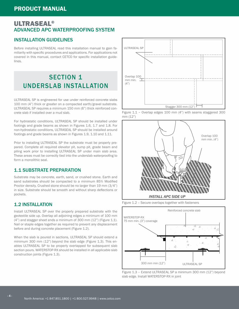
1.2 INSTALLATION
Install ULTRASEAL SP over the properly prepared substrate with the
geotextile side up. Overlap all adjoining edges a minimum of 100 mm
(4”) and stagger sheet ends a minimum of 300 mm (12”) (Figure 1.1).
Nailorstapleedgestogetherasrequiredtopreventanydisplacementbefore and during concrete placement (Figure 1.2).
Whentheslabispouredinsections,ULTRASEALSPshouldextendaminimum 300 mm (12”) beyond the slab edge (Figure 1.3). This en-
ables ULTRASEAL SP to be properly overlapped for subsequent slab
sectionpours.WATERSTOP-RXshouldbeinstalledinallapplicableslabconstruction joints (Figure 1.3).
Figure 1.1 – Overlap edges 100 mm (4”) with seams staggered 300
mm (12”)
ULTRASEAL SP
Overlap 100 mm min. (4”)
Stagger 300 mm (12”)
INSTALL APC SIDE UP
Overlap 100 mm min. (4”)
Figure 1.2 – Secure overlaps together with fasteners
Figure 1.3 – Extend ULTRASEAL SP a minimum 300 mm (12”) beyond
slabedge.InstallWATERSTOP-RXinjoint
Reinforced concrete slab
300 mm min (12”) ULTRASEAL SP
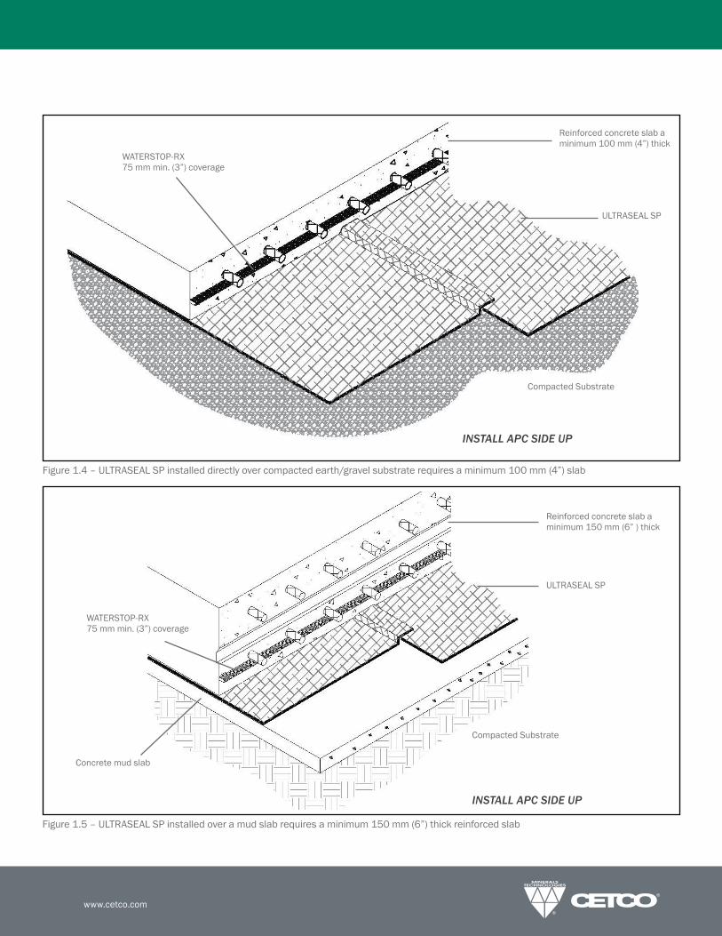
WATERSTOP-RX 75 mm min. (3”) coverage
www.cetco.com
WATERSTOP-RX 75 mm min. (3”) coverage
Reinforced concrete slab a minimum 100 mm (4”) thick
ULTRASEAL SP
Compacted Substrate
INSTALL APC SIDE UP
Figure 1.4 – ULTRASEAL SP installed directly over compacted earth/gravel substrate requires a minimum 100 mm (4”) slab
Figure 1.5 – ULTRASEAL SP installed over a mud slab requires a minimum 150 mm (6”) thick reinforced slab
Reinforced concrete slab a minimum 150 mm (6” ) thick
ULTRASEAL SP
Compacted Substrate
Concrete mud slab
INSTALL APC SIDE UP
WATERSTOP-RX 75 mm min. (3”) coverage

PRODUCT MANUAL
- 6 -North America: +1 847.851.1800 | +1 800.527.9948 | www.cetco.com
ULTRASEAL®
ADVANCED APC WATERPROOFING SYSTEM
HYDROSTATIC CONDITIONS NON-HYDROSTATIC CONDITIONS
Figure 1.6 – Slab on footing detail (hydrostatic)
ULTRASEAL BT
ULTRASEAL SP
Hydrobar Tube
WATERSTOP-RX 75 mm min. (3”) coverage
Figure 1.7 – Raised slab detail with mud slab (hydrostatic)
ULTRASEAL BT
BENTOSEAL
Hydrobar Tube
ULTRASEAL SP
Mud slab
WATERSTOP-RX 75 mm min. (3”) coverage
Figure1.8–Flushslabdetailpropertylinewall(hydrostatic)
ULTRASEAL SP
ULTRASEAL BT
WATERSTOP-RX 75 mm min. (3”) coverage
Figure1.11–Flushslabdetailbackilledwall(non-hydrostatic)
ULTRASEAL BT
Term Bar & BENTOSEAL
300 mm (12”)
WATERSTOP-RX 75 mm min. (3”) coverage
Figure 1.10 – Raised slab detail with mud slab (non-hydrostatic)
ULTRASEAL BT
BENTOSEAL
ULTRASEAL SP
Mud slab
WATERSTOP-RX 75 mm min. (3”) coverage
Figure 1.9 – Slab on footing detail (non-hydrostatic)
ULTRASEAL BT
Hydrobar Tube
WATERSTOP-RX 75 mm min. (3”) coverage
Term bar and BENTOSEAL

www.cetco.com
1.3 PILE CAPS AND GRADE BEAMS
ULTRASEAL SP is typically not installed over pile caps but cut to ittightly around pile caps. Then apply a minimum 19 mm (3/4”) thick
illetofBENTOSEALat intersectionofmembraneandthepiling (Fig-
ure1.12)withWaterstoppageunderthemembraneatthepilingedge.BENTOSEALshouldextendontothemembraneandpilingaminimumof50mm(2”)at19mm(3/4”)thickness.WATERSTOP-RXshouldbe
installed on top surface of pile cap around reinforcing steel (Figure
1.12).
Detail grade beams the same as pile caps (Figure 1.14) with a non-hy-
drostatic condition. For hydrostatic conditions, ULTRASEAL SP should
be installed under the entire grade beam (Figure 1.15). Line the grade
beam formwork with ULTRASEAL SP prior to placement of reinforcing
steel. Leave a minimum 300 mm (12”) of ULTRASEAL SP at the top of
theformtotieintobelowslabwaterprooing.
Figure1.13–PileCapDetail(Non-hydrostaticcondition)
WATERSTOP-RXWaterstoppage
ULTRASEAL SP
BENTOSEAL
Pile cap
BENTOSEAL
Pile
Figure1.14–GradeBeam(Non-hydrostaticcondition)
WATERSTOP-RX Reinforcing steal BENTOSEAL
ULTRASEAL SP
Grade beam
50 mm (2”) thick illetof Waterstoppage
Figure 1.12 – Pile Cap Detail (Hydrostatic condition)
WATERSTOP-RX
Concrete pile
BENTOSEAL
ULTRASEAL SP
Waterstoppage
WATERSTOP-RX
Metal I-beam
ULTRASEAL SP
WATERSTOP-RX
50mm(2”)thickilletofBENTOSEAL
Figure 1.15 – Grade Beam (Hydrostatic condition)
Grade beam
Reinforcing stealWATERSTOP-RX
ULTRASEAL SP

PRODUCT MANUAL
- 8 -North America: +1 847.851.1800 | +1 800.527.9948 | www.cetco.com
ULTRASEAL®
ADVANCED APC WATERPROOFING SYSTEM
1.4 SLAB PENETRATIONS
Cut ULTRASEAL SP to closely it around penetrations (Figure 1.16).Trowelaminimum19mm(3/4”)thickilletofBENTOSEALaroundthepenetrationtocompletelyillanyvoidareabetweenULTRASEALSPandthepenetration(Figure1.17).TheBENTOSEALshouldextendupthepenetrationabout38mm(1–1/2”)andextendontothemembrane.In areas where multiple penetrations are close together, it may be im-
practical to cut ULTRASEAL SP to it around each penetration. PourWaterstoppageaminimum6mm(1/4”)thickaroundthepenetrationscoveringtheentiresubstratearea.Withgravelsubstrate,installmini-mum8"(200mm)collarofULTRASEALSParoundpenetrationpriortoplacingWaterstoppage.ThenapplyathicklayerofBENTOSEALaroundeach penetration as detailed (Figure 1.19).
Figure1.17–BENTOSEALtroweledaroundpenetrations
ULTRASEAL SP
Pipe
BENTOSEAL
INSTALL APC SIDE UP
Figure1.18–Slabpenetrationcrosssectiondetail
ULTRASEAL SP
Waterstoppage
BENTOSEAL
WATERSTOP-RX 75 mm min. (3”) coverage
Pipe
Mud slab
Figure1.19–Multiplepipepenetrations.TrowelBENTOSEALaroundpipesandcoveringareabetweenthepipes
Mud Slab Substrate Compacted Earth or Gravel Substrate
WATERSTOP-RX
BENTOSEAL
Continue ULTRASEAL SP between pipes
ULTRASEAL SP
WaterstoppageMud slab substrate
Continue ULTRASEAL SP between pipes
WATERSTOP-RX
BENTOSEAL
Gravel substrate
ULTRASEAL SP collar Waterstoppage
www.cetco.com
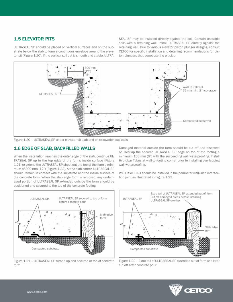
1.5 ELEVATOR PITS
ULTRASEAL SP should be placed on vertical surfaces and on the sub-
strate below the slab to form a continuous envelope around the eleva-
tor pit (Figure 1.20). If the vertical soil cut is smooth and stable, ULTRA-
SEAL SP may be installed directly against the soil. Contain unstable
soils with a retaining wall. Install ULTRASEAL SP directly against the
retaining wall. Due to various elevator piston plunger designs, consult
CETCOforspeciicinstallationanddetailingrecommendationsforpis-
ton plungers that penetrate the pit slab.
1.6 EDGE OF SLAB, BACKFILLED WALLS
Whentheinstallationreachestheouteredgeoftheslab,continueUL-
TRASEAL SP up to the top edge of the forms inside surface (Figure
1.21) or extend the ULTRASEAL SP sheet out the top of the form a mini-
mum of 300 mm (12”) (Figure 1.22). At the slab corner, ULTRASEAL SP
should remain in contact with the substrate and the inside surface of
theconcreteform.Whentheslabedgeformisremoved,anyundam-
aged portion of ULTRASEAL SP extended outside the form should be
positioned and secured to the top of the concrete footing.
Damaged material outside the form should be cut off and disposed
of. Overlap the secured ULTRASEAL SP edge on top of the footing a
minimum150mm(6”)withthesucceedingwallwaterprooing.InstallHydrobar Tubes at wall-to-footing corner prior to installing overlapping
wallwaterprooing.
WATERSTOP-RXshouldbeinstalledintheperimeterwall/slabintersec-
tion joint as illustrated in Figure 1.23.
Figure 1.21 – ULTRASEAL SP turned up and secured at top of concrete
form
Figure 1.22 – Extra tail of ULTRASEAL SP extended out of form and later
cut off after concrete pour
ULTRASEAL SP ULTRASEAL SP secured to top of form before concrete pour
Slab edge form
Compacted substrate
ULTRASEAL SP
Extra tail of ULTRASEAL SP extended out of form. Cut off damaged areas before installing ULTRASEAL SP overlap
Slab edge form
Compacted substrate
Figure 1.20 – ULTRASEAL SP under elevator pit slab and on excavation cut walls
ULTRASEAL SP
Compacted substrate
WATERSTOP-RX 75 mm min. (3”) coverage
300 mm (12”) min

PRODUCT MANUAL
- 10 -North America: +1 847.851.1800 | +1 800.527.9948 | www.cetco.com
ULTRASEAL®
ADVANCED APC WATERPROOFING SYSTEM
1.7 EDGE OF SLAB, PROPERTY LINE
CONSTRUCTIONWhereproperty lineretainingwalls,suchassoldierpileandlagging,are used as the outside form, it is very important to extend the wa-
terprooingaminimum300mm(12”)abovethetopoftheslabsincethere is no access to the outer edge of the slab after it is poured.
Slab to Wall Corner Transition:InstallULTRASEALBTsheethorizon-
tally oriented (APC side facing installer) with a minimum 300 mm (12”)
ofthesheetextendingoutontothehorizontalsubstrate.Thetopedgeofthesheetmustextendaminimum300mm(12”)abovetheinishedslab surface. Secure ULTRASEAL BT sheet to lagging wall with washer-
head fastener maximum 600 mm (24”) on center. Overlap edges of
adjacent ULTRASEAL BT sheets a minimum 100 mm (4”).
If the slab thickness is greater than 600 mm (24”), install a second
fullsheetorcutstripofULTRASEALBT,horizontallyoriented,tomeetthe 300 mm (12”) requirement above the slab. Overlap top edge of
previous sheet and edges of adjacent sheets a minimum 100 mm (4”).
Base Wall Course: InstallirstULTRASEALBTsheetcourseon theshoringwallhorizontallyoriented (APCside facing installer)over the
corner transition sheet, with the bottom edge extending down to the
wall/slab transition corner as shown in Figure 1.23. Secure ULTRASE-
AL BT sheet to lagging wall with washer-head fasteners maximum 600
mm (24”) on center. Overlap edges of adjacent ULTRASEAL BT sheets
a minimum 100 mm (4”).
Install underslab ULTRASEAL SP membrane extending to corner transi-
tion, overlapping the 300 mm (12”) sheet tail of the corner transition
sheet installed at the wall base. Secure corner edge with fasteners
300 mm (12”) on center.
Formetalsheetpilingshoringwalls,irstinstalltheULTRASEALBTcor-nertransitionsheethorizontallyorientedwiththebottomedgeextend-
ing minimum 300 mm (12”) out onto the substrate. Cut the bottom
edge of the corner transition sheet at piling transition angles to allow
thebottomedgetolaylatontothesubstrate.Pour38mm(11/2”)continuouscantofWaterstoppagealongbaseofshoringwall.Thenin-
stallunderslabULTRASEALSPsheetcuttoitcontoursofmetalsheetpiling. Finally, install the base shoring wall ULTRASEAL BT sheet (hori-
zontallyoriented)overlappingthecornertransitionsheet.
Figure1.23–SLAB-TO-WALLTRANSITION–ULTRASEALBTcornertran-
sitionsheetshouldextendpast theheightof the topof theinishedslab level a minimum 300 mm (12”) and extend under the slab 300
mm (12”)
Figure1.24–AQUADRAIN100BDDISCHARGEPIPE–ConnectAQUAD-
RAIN100BDtowaterdischargepipesusing100BDaccessorycon-
nections
ULTRASEAL SP under slab
ULTRASEAL BT transition sheet at corner installedhorizontallyoriented
Cast-in-place concrete wall
ULTRASEAL BT base course installedhorizontallyoriented
Woodlagging
300 mm (12”) min
ULTRASEAL BT base course installed horizontallyoriented
AQUADRAIN Sheet Drain
Woodlagging
12"(300 mm) min
AQUADRAIN100BDbasedrainconnected to discharge pipes
ULTRASEAL BT transition sheet at cornerinstalledhorizontallyoriented
ULTRASEAL SP
Discharge Pipe
WATERSTOP-RX 75 mm min. (3”) coverage
WATERSTOP-RX 75 mm min. (3”) coverage
300 mm (12”)
BENTOSEAL
www.cetco.com
SECTION 2
PROPERTY LINE CONSTRUCTION
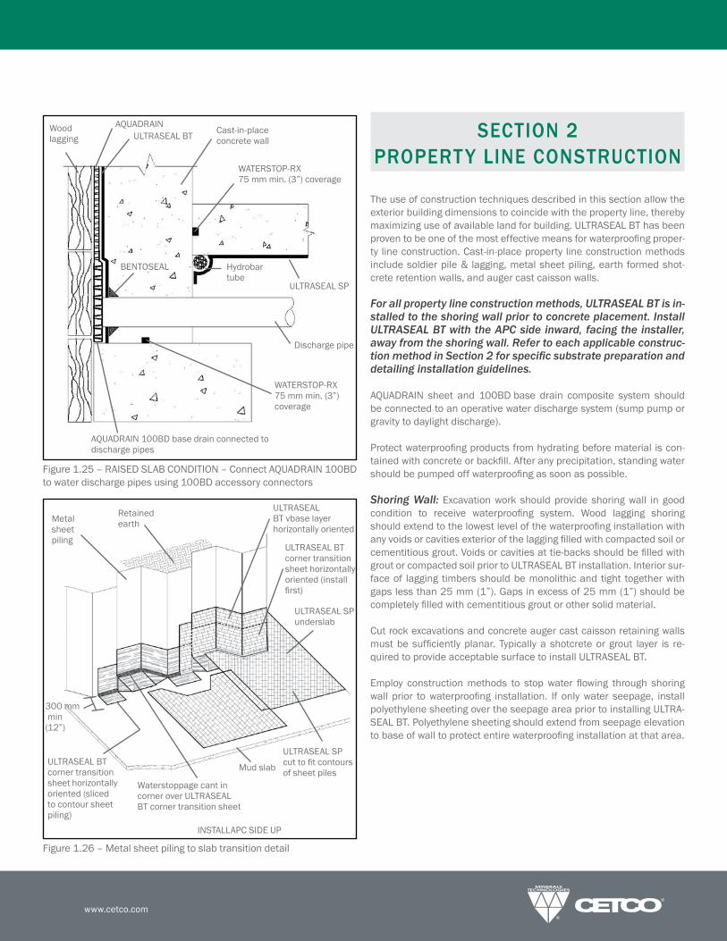
The use of construction techniques described in this section allow the
exterior building dimensions to coincide with the property line, thereby
maximizinguseofavailablelandforbuilding.ULTRASEALBThasbeenproventobeoneofthemosteffectivemeansforwaterprooingproper-ty line construction. Cast-in-place property line construction methods
include soldier pile & lagging, metal sheet piling, earth formed shot-
crete retention walls, and auger cast caisson walls.
For all property line construction methods, ULTRASEAL BT is in-stalled to the shoring wall prior to concrete placement. Install ULTRASEAL BT with the APC side inward, facing the installer, away from the shoring wall. Refer to each applicable construc-tion method in Section 2 for speciic substrate preparation and detailing installation guidelines.
AQUADRAIN sheet and 100BDbase drain composite system shouldbe connected to an operative water discharge system (sump pump or
gravity to daylight discharge).
Protectwaterprooingproductsfromhydratingbeforematerialiscon-
tainedwithconcreteorbackill.Afteranyprecipitation,standingwatershouldbepumpedoffwaterprooingassoonaspossible.
Shoring Wall: Excavation work should provide shoring wall in good
condition to receive waterprooing system. Wood lagging shoringshouldextendtothelowestlevelofthewaterprooinginstallationwithanyvoidsorcavitiesexteriorofthelaggingilledwithcompactedsoilorcementitiousgrout.Voidsorcavitiesattie-backsshouldbeilledwithgrout or compacted soil prior to ULTRASEAL BT installation. Interior sur-
face of lagging timbers should be monolithic and tight together with
gaps less than 25 mm (1”). Gaps in excess of 25 mm (1”) should be
completelyilledwithcementitiousgroutorothersolidmaterial.
Cut rock excavations and concrete auger cast caisson retaining walls
mustbesuficientlyplanar. Typicallyashotcreteorgrout layer is re-
quired to provide acceptable surface to install ULTRASEAL BT.
Employ construction methods to stop water lowing through shoringwall prior to waterprooing installation. If only water seepage, installpolyethylene sheeting over the seepage area prior to installing ULTRA-
SEAL BT. Polyethylene sheeting should extend from seepage elevation
tobaseofwalltoprotectentirewaterprooinginstallationatthatarea.
Figure1.25–RAISEDSLABCONDITION–ConnectAQUADRAIN100BDto water discharge pipes using 100BD accessory connectors
Figure 1.26 – Metal sheet piling to slab transition detail
Cast-in-place concrete wall
AQUADRAINULTRASEAL BT
Wood lagging
Hydrobar tube
ULTRASEAL SP
Discharge pipe
AQUADRAIN100BDbasedrainconnectedtodischarge pipes
WATERSTOP-RX 75 mm min. (3”) coverage
WATERSTOP-RX 75 mm min. (3”) coverage
BENTOSEAL
ULTRASEAL SP underslab
300 mm min (12”)
Waterstoppagecantincorner over ULTRASEAL BT corner transition sheet
Metal sheetpiling
ULTRASEAL BT vbase layer horizontallyoriented
Retained earth
ULTRASEAL BT corner transition sheethorizontallyoriented (install irst)
ULTRASEAL BT corner transition sheethorizontallyoriented (sliced to contour sheet piling)
ULTRASEAL SP cuttoitcontoursof sheet piles
Mud slab
INSTALLAPCSIDEUP

PRODUCT MANUAL
- 12 -North America: +1 847.851.1800 | +1 800.527.9948 | www.cetco.com
ULTRASEAL®
ADVANCED APC WATERPROOFING SYSTEM
2.1 PROPERTY LINE WALL INSTALLATION
GUIDELINES
After the slab-to-wall corner transition sheet and bottom wall sheet
course have been installed per Section 1.7 Page 10, ULTRASEAL BT
sheetscanbeinstalledeitherverticallyorhorizontallyoriented.Fastenthe ULTRASEAL BT into position with washer-head fasteners maximum
600 mm (24”) on center around the sheet edge. Install succeeding
sheetoverlappingtheprevioussheetedge100mm(4”).(Note:Shin-
gle lap seams so that the bottom edge of the upper sheet is over the
lower sheets top edge).
Continue installation up wall until grade elevation detail, or as speci-
ied,staggeringallsheetendsofadjacentrollsaminimum300mm(12”). Do not allow sheet overlap joints to occur at same elevation as
concrete cold joints. Plan by chalk lining the location of construction
joints.
Penetrations: Install a cut collar of ULTRASEAL BT tightly around the
penetration;extendingaminimum300mm(12”)radius.ApplyBEN-
TOSEALoverULTRASEALBTcollararoundpenetration;extendingBEN-
TOSEAL a minimum 75 mm (3”) radius at 6 mm (1/4”) thickness. Then
install main course of ULTRASEAL BT membrane tightly around the
penetration. Finally, detail around penetration with 19 mm (3/4”) thick
cantofBENTOSEAL.Withsleevedpipes,Theconcreteworkshouldin-
cludeillingthegapbetweenthepipeandthesleevewithnon-shrinkcementitiousgrout,mechanicalsealbyothersandinstallWATERSTOP-RXtooutsideofsleeve.
Tie-Back Covers:SelectappropriatesizeTB-Boottoitovertie-backplate and allow proper cast-in-place concrete coverage per project re-
quirements.TB-Bootshoulditoverentire tie-backheadwithout thetie-back plate or cables in direct contact with the TB-Boot. Prior to
TB-Bootinstallation,illvoidsinretentionwallsubstrateandtie-backhead assembly with spray foam (min 20 psi) or non-shrink grout. For
non-hydrostatic conditions, install and secure AQUADRAIN drainagecomposite course per manufacturer’s guidelines to soil retention wall
prior to installing TB-Boot. For hydrostatic conditions, install TB-Boot
priortoULTRASEALBTmembrane.Withsoldierpiles,strippileswithwaterprooingmembranepriortoTB-Bootplacement.
Fill pre-formed shape of TB-Boot with 2-part urethane spray foam (min
20 PSI) and place over tie-back head before foam sets up. Secure TB-
Boot to soil retention system using washer head fasteners along the
outsideedgeofthelatbase.Apply6mm(1/4”)thickbyminimum3”(75mm)widecontinuousringofBENTOSEALontothelatbase justoutside of the 12 mm (1/2”) raised collar. Install 4-ft by 4-ft piece of
ULTRASEAL BT (with precuthole in center to it tight around the 12mm (1/2”) raised collar) over the entire lat base with outside edg-
es fastened to the retaining wall. Secure inside ULTRASEAL BT edge
around raised collar with washer-head fasteners that pass through the
BENTOSEALring;typicalfastenerspacing150mm(6”).Donotinstallfasteners or puncture TB-Boot inside of the 12 mm (1/2”) raised collar.
ApplycounterlashingofBENTOSEALalongULTRASEALBTsheetedgearound raisedcollar. Then installULTRASEALBTieldsheetoverlap-
ping outer membrane edge minimum 100 mm (4”).
Figure2.1–WALLPENETRATION–CutandsecureULTRASEALBTtight-lyaroundpenetrationsandthenapplyBENTOSEAL19mm(3/4”)ringaround penetration and extend over membrane a minimum 75 mm (3”)
radius at minimum 6 mm (1/4”) thickness
Figure2.2–SLEEVEDWALLPENETRATION–CutandsecureULTRA-
SEALBTtightlyaroundpenetrationsandthenapplyBENTOSEAL19mm(3/4”) ring around penetration and extend over membrane a min. 75
mm (3”)
300 mm (12”) min
Woodlagging
300mm(12")ULTRASEALBT collar around pipe penetration
19mm(3/4") BENTOSEALcant
WATERSTOP-RX
Pipe
Cast-in-place concrete wall
ULTRASEAL BT
AQUADRAINSheetDrain
BENTOSEALring 6 mm x 75 mm (1/4” x 3”) min
300 mm (12”) min
Woodlagging
300mm(12")ULTRASEALBT collar around pipe penetration
19mm(3/4")BENTOSEALcant
WATERSTOP-RX
Pipe
ULTRASEAL BT
AQUADRAINSheetDrain
Pipesleeve,illedwith non-shrink grout
Cast-in-place concrete wall
BENTOSEALring 6 mm x 75 mm (1/4” x 3”)
Mechanical seal by others

www.cetco.com
Soldier Pile Stripping: Install a strip of ULTRASEAL BT over all soldier
piles with raised lagging hanger bolts, form tie rods, or other irregular
surface. ULTRASEAL BT strip should extend a minimum 150 mm (6”)
tobothsidesofthepiling.ApplyBENTOSEAL6mmx50mm(1/4”x2”) to ULTRASEAL BT strip surface along both edges of each soldier
pile (Figure 2.9).
Cementitious Board: Prior to installing ULTRASEAL BT to inishedgrade, install 12 mm (1/2”) thick cementitious wall board centered
oversteelsoldierpilefrominishedgradeelevationtospeciieddepththat the top of steel soldier pile and wood lagging will be removed (Fig-
ure 2.13).
Grade Termination: Terminate ULTRASEAL BT membrane 300 mm
(12”)belowinishedgradeelevationwithwasher-headfastenersmaxi-mum300mm(12”)oncenter.InstallENVIROSHEETlashingtoprimedconcrete substrate with bottom edge overlapping top edge of ULTRA-
SEAL BT membrane minimum 100 mm (4”). Overlap all roll ends a min-
imum100mm(4”)toformacontinuouslashing.Heightoflashingshallbeperprojectdetailsandspeciications.Installarigidtermina-
tionbaralongtopedgeofENVIROSHEET;fastenedmaximum300mm(12”) on center. Complete grade termination detail with tooled bead of
CETSEALalongthetopedge,atallpenetrationsthroughthelashing,and all exposed overlap seams.
Where lagging timbersand the topendofsteelsoldierpilesare re-
moved, repairanywaterprooingdamagedby theexcavationandre-
moval of the retention wall system. Secure all excavated ULTRASEAL
BT overlap seams with washer-head fasteners maximum 600 mm
(24”) on center and then apply Seamtape centered along overlap
seams.Backillshallbeplacedandcompactedtominimum85%Mod-
iied Proctor density promptly after waterprooing installation. Back-
illshouldconsistofcompactablesoilorangularaggregate (19mm(3/4”) or less) free of debris, sharp objects, and stones larger than 19
mm (3/4”). See termination details, Figure 3.11 and 3.12, page 22.
Figure2.3:TIE-BACKDETAIL–InstallTB–Bootcenteredovertie-backtheninstallmaincourseofULTRASEALBTwithBENTOSEALdetailing.Do not fasten boot inside of raised collar around center formed area
Shoring wall
ULTRASEAL BT
AQUADRAINsheetdrain
2-part urethane expanding spray foam (min. 20 PSI)
Soldier pile
Fastener
Use spray foamtoillall voids behind tie-back
Do not fasten boot inside of raised collar
Tie-back head with cables
CETCO pre-formed TB-Boot
BENTOSEAL6mmx75mm(1/4” x 3”) min ULTRASEAL BT
Field Sheet
Concrete wall
Fastener
Raised collar
Figure2.3a:TIE-BACKDETAIL–InstallTB-Bootcenteredovertie-backthen installULTRASEALBTwithBENTOSEALdetailing.Donot fastenboot inside of raised collar around center formed area
Shoring wall
Soldier pile
Fastener
ULTRASEAL BT pile strip
ULTRASEAL BT
Raised collar
TB-Boot
Fastener
Soldier pile
ULTRASEAL BT ieldsheet
Use spray foamtoillall voids behind tie-back
Do not fasten boot inside of raised collar
ULTRASEAL BT pile strip
ULTRASEAL BT pile strip
Tie-back head with cables
CETCO pre-formed TB-Boot
2-part urethane expanding spray foam (min. 20 PSI)
ULTRASEAL BT ieldsheet
BENTOSEAL 6 mm x 75 mm (1/4” x 3”) min
NON-HYDROSTATIC CONDITIONS HYDROSTATIC CONDITIONS
BENTOSEAL
Soldier pile
AQUADRAIN
BENTOSEAL
BENTOSEAL
BENTOSEAL
PRODUCT MANUAL
- 14 -North America: +1 847.851.1800 | +1 800.527.9948 | www.cetco.com
ULTRASEAL®
ADVANCED APC WATERPROOFING SYSTEM
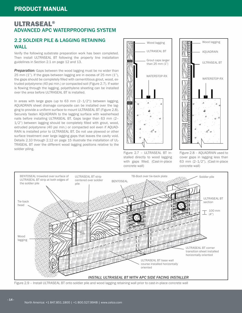
2.2 SOLDIER PILE & LAGGING RETAINING
WALL
Verify the following substrate preparation work has been completed.
Then install ULTRASEAL BT following the property line installation
guidelines in Section 2.1 on page 12 and 13.
Preparation: Gaps between the wood lagging must be no wider than
25 mm (1”). If the gaps between lagging are in excess of 25 mm (1”),
thegapsshouldbecompletelyilledwithcementitiousgrout,wood,ex-
truded polystyrene (40 psi min.) or compacted soil (Figure 2.7). If water
islowingthroughthelagging,polyethylenesheetingcanbeinstalledover the area before ULTRASEAL BT is installed.
In areas with large gaps (up to 63 mm (2–1/2")) between lagging,AQUADRAINsheetdrainagecompositecanbe installedover the lag-
gingtoprovideauniformsurfacetomountULTRASEALBT(Figure2.8).Securely fastenAQUADRAIN to the laggingsurfacewithwasherheadnails before installing ULTRASEAL BT. Gaps larger than 63 mm (2–
1/2”)between laggingshouldbecompletely illedwithgrout,wood,extruded polystyrene (40 psi min.) or compacted soil even if AQUAD-
RAINisinstalledpriortoULTRASEALBT.Donotuseplywoodorothersurface treatment over large lagging gaps that leaves the cavity void.
Details 2.10 through 2.12 on page 15 illustrate the installation of UL-
TRASEAL BT over the different wood lagging positions relative to the
soldier piling.Figure 2.7 – ULTRASEAL BT in-
stalled directly to wood lagging
with gaps illed. (Cast-in-placeconcrete wall)
Figure2.8–AQUADRAINusedtocover gaps in lagging less than
63 mm (2–1/2”). (Cast-in-place
concrete wall)
Woodlagging
ULTRASEAL BT
Grout caps larger than 25 mm (1”)
WATERSTOP-RX
Woodlagging
ULTRASEAL BT
AQUADRAIN
WATERSTOP-RX
Figure 2.9 – Install ULTRASEAL BT onto soldier pile and wood lagging retaining wall prior to cast-in-place concrete wall
BENTOSEALtroweledoversurfaceofULTRASEAL BT strip at both edges of the soldier pile
ULTRASEAL BT strip centered over soldier pile
BENTOSEALTB-Boot over tie-back plate
ULTRASEAL BT corner transition sheet installed horizontallyoriented
ULTRASEAL BT base wall courseinstalledhorizontallyoriented
INSTALL ULTRASEAL BT WITH APC SIDE FACING INSTALLER
Wood lagging
Tie-back head
Soldier pile
ULTRASEAL BT section
100 mm (4”)
www.cetco.com
Wood lagging
Steel piling
ULTRASEAL BT main course
ULTRASEAL BT strip over pile prior to main course
WATERSTOP-RX (75 mm min (3”) coverage)
BENTOSEAL
Cast-in-place concrete wall
Woodlagging
Steel piling
Retained earth
ULTRASEAL BT main course
BENTOSEAL between sheets of ULTRASEAL
ULTRASEAL BT strip over pile prior to main course
Fill gap with solid material
Cast-in-place concrete wall
Plate & bolts secure lagging
WATERSTOP-RX (75 mm min (3”) coverage)
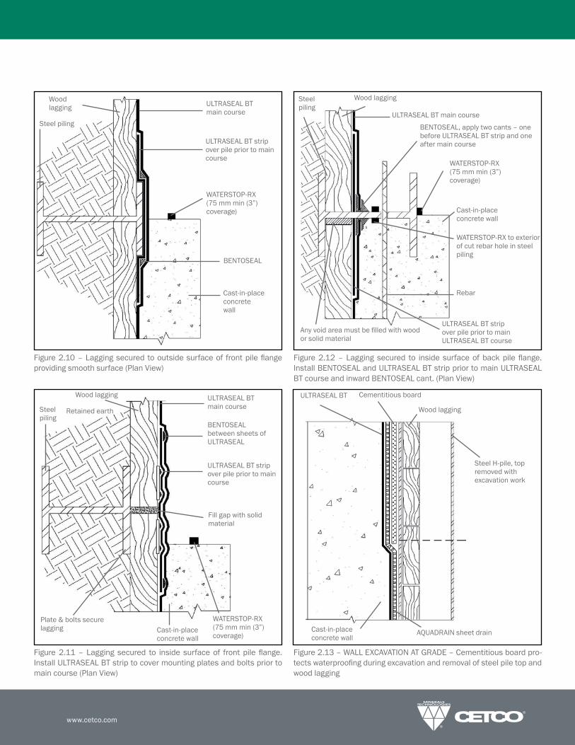
Figure 2.11 – Lagging secured to inside surface of front pile lange.Install ULTRASEAL BT strip to cover mounting plates and bolts prior to
main course (Plan View)
Figure2.10–Laggingsecuredtooutsidesurfaceof frontpilelangeproviding smooth surface (Plan View)
Figure2.12–Laggingsecured to insidesurfaceofbackpile lange.InstallBENTOSEALandULTRASEALBTstrippriortomainULTRASEALBTcourseandinwardBENTOSEALcant.(PlanView)
Steel piling
Woodlagging
ULTRASEAL BT main course
BENTOSEAL,applytwocants–onebefore ULTRASEAL BT strip and one after main course
Cast-in-place concrete wall
WATERSTOP-RXtoexteriorof cut rebar hole in steel piling
Rebar
ULTRASEAL BT strip over pile prior to main ULTRASEAL BT course
Anyvoidareamustbeilledwithwoodor solid material
WATERSTOP-RX (75 mm min (3”) coverage)
Figure2.13–WALLEXCAVATIONATGRADE–Cementitiousboardpro-
tectswaterprooingduringexcavationandremovalofsteelpiletopandwood lagging
ULTRASEAL BT Cementitious board
Woodlagging
Steel H-pile, top removed with excavation work
AQUADRAINsheetdrainCast-in-place concrete wall

PRODUCT MANUAL
- 16 -North America: +1 847.851.1800 | +1 800.527.9948 | www.cetco.com
ULTRASEAL®
ADVANCED APC WATERPROOFING SYSTEM
Figure 2.14 – Sheet pile interlock detail
Figure 2.15 – Install ULTRASEAL BT onto metal sheet piling retaining wall with powder-actuated fasteners
2.3 METAL SHEET PILING RETAINING WALL
Verify the following substrate preparation work has been completed.
Then install ULTRASEAL BT following the property line installation
guidelines in Section 2.1 on page 12 and 13. Special knurled powder-
actuated fasteners are recommended to secure ULTRASEAL to the
metal sheet piling.
Preparation:Trowela12mm(1/2”)thicklayerofBENTOSEALalongall sheet piling knuckles. Fill voids or cavities at tie-back plates with ce-
mentitious grout or compacted soils. If excessive water is penetrating
the sheet piling knuckles, Bentogrout can be injected to the outside of
theknuckletostopwaterlow(Figure2.14).ConsultCETCOforBento-
grout applications and installation guidelines.
Alternate Plywood MethodAlternatively, 12 mm (1/2”) plywood may be fastened to the sheet pil-
ingtocreatealatsurfaceuponwhichULTRASEALBTisfastened.Allvoidspacesbetweentheplywoodandsheetpilingmustbeilledwithcompacted earth or concrete. Apply ULTRASEAL BT to plywood follow-
ing “Property Line Construction” Guidelines in Section 2, Page 11.
Bentogrout injected to exterior side of sheet pile interlock (per project requirements)
Retained earth
Sheet piling
ULTRASEAL BTBENTOSEALSheet pile interlock
Cast-in-place concrete wall
ULTRASEAL BT vertical seams should not occur at interlocking of sheet piling
ULTRASEAL BT
WATERSTOP-RX (75 mm min (3”) coverage)
Retained earth
Metal sheet piling
Completelyillareabehind plywood with compacted soil or concrete
Optionaltechnique:plywood fastened to sheet piling to form latsurfacetomountULTRASEAL BT
Install APC side facing installer
www.cetco.com
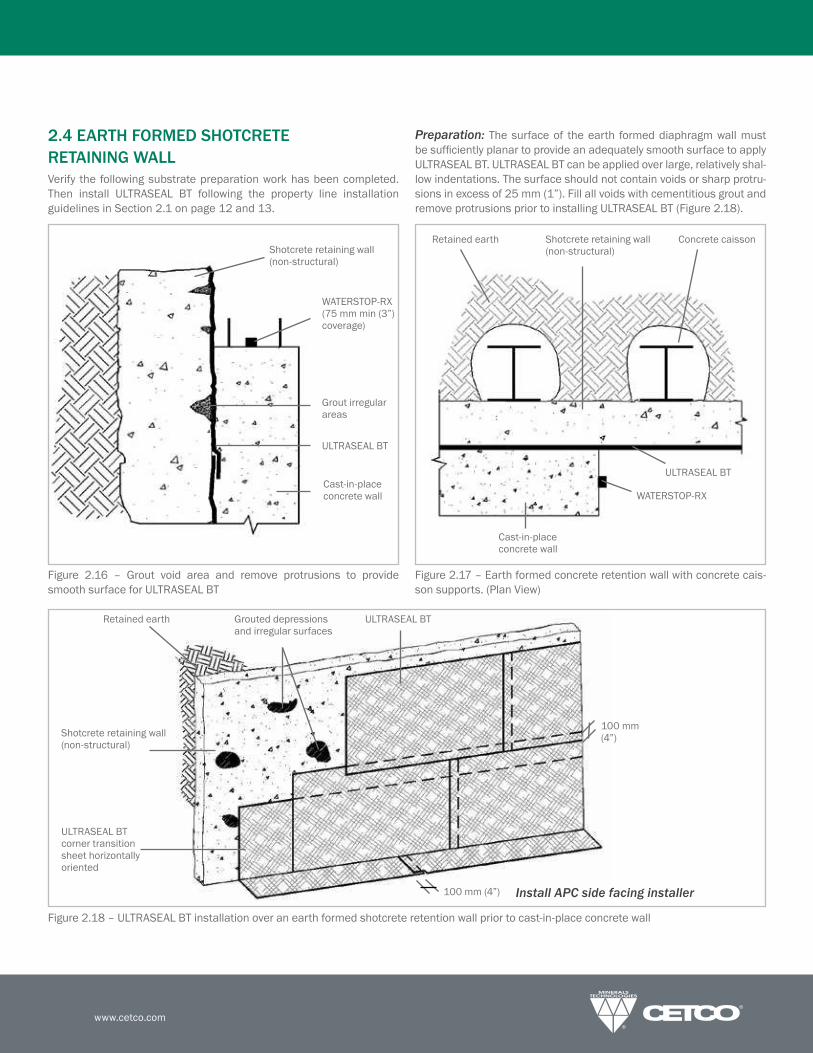
2.4 EARTH FORMED SHOTCRETE
RETAINING WALL
Verify the following substrate preparation work has been completed.
Then install ULTRASEAL BT following the property line installation
guidelines in Section 2.1 on page 12 and 13.
Preparation: The surface of the earth formed diaphragm wall must
besuficientlyplanartoprovideanadequatelysmoothsurfacetoapplyULTRASEAL BT. ULTRASEAL BT can be applied over large, relatively shal-
low indentations. The surface should not contain voids or sharp protru-
sions in excess of 25 mm (1”). Fill all voids with cementitious grout and
removeprotrusionspriortoinstallingULTRASEALBT(Figure2.18).
Figure 2.17 – Earth formed concrete retention wall with concrete cais-
son supports. (Plan View)
Figure2.18–ULTRASEALBTinstallationoveranearthformedshotcreteretentionwallpriortocast-in-placeconcretewall
Figure 2.16 – Grout void area and remove protrusions to provide
smooth surface for ULTRASEAL BT
WATERSTOP-RX (75 mm min (3”) coverage)
Grout irregular areas
ULTRASEAL BT
Cast-in-place concrete wall
Shotcrete retaining wall (non-structural)
Shotcrete retaining wall (non-structural)
ULTRASEAL BT
WATERSTOP-RX
Cast-in-place concrete wall
Retained earth Concrete caisson
Retained earth
Shotcrete retaining wall (non-structural)
ULTRASEAL BT
ULTRASEAL BT corner transition sheethorizontallyoriented
Grouted depressions and irregular surfaces
100 mm (4”)
100 mm (4”) Install APC side facing installer

PRODUCT MANUAL
- 18 -North America: +1 847.851.1800 | +1 800.527.9948 | www.cetco.com
ULTRASEAL®
ADVANCED APC WATERPROOFING SYSTEM
Figure2.19–CutRockexcavationwithshotcreteappliedtoprovideasmoothsurfaceforwaterprooinginstallation
Figure 2.20 – Fill in recesses between cast caissons with grout to pro-
vide smooth surface (Plan View)
2.5 AUGER CAST CAISSON WALLS
Verify the following substrate preparation work has been completed.
Then install ULTRASEAL BT following the property line installation
guidelines in Section 2.1 on page 12 and 13.
Preparation:Thesurfaceofaugercastcaissonandcutrockexcavationwallsmustbesuficientlyplanartoprovideanadequatelysmoothsur-face to apply ULTRASEAL BT. ULTRASEAL BT can be applied over large,
relatively shallow indentations where it can conform tight against the
surface. The surface should not contain voids or sharp protrusions in
excess of 25 mm (1”). Fill all large recesses between caissons with
cementitious grout prior to installing ULTRASEAL BT (Figure 2.20). Cut
rock excavations typically require shotcrete or grout work to provide ac-
ceptable surface to install ULTRASEAL BT (Figure 2.19).
Figure 2.21 – ULTRASEAL BT installation over an auger cast concrete retention wall prior to cast-in-place concrete wall
Retained earth side Concrete caisson
ULTRASEAL BT Grout recesses
Retained earth
ULTRASEAL BT
100 mm (4”)
ULTRASEAL BT corner transition sheet horizontallyoriented
Shotcrete retaining wall (non-structural)
Grouted depressions and irregular surfaces
Cut rock formation from excavation
Shotcrete applied to cut rock surface (non-structural)
ULTRASEAL BT TB-6SNULTRASEAL BT
WATERSTOP-RX
BENTOSEAL detailing
Install APC side facing installer
www.cetco.com
SECTION 3
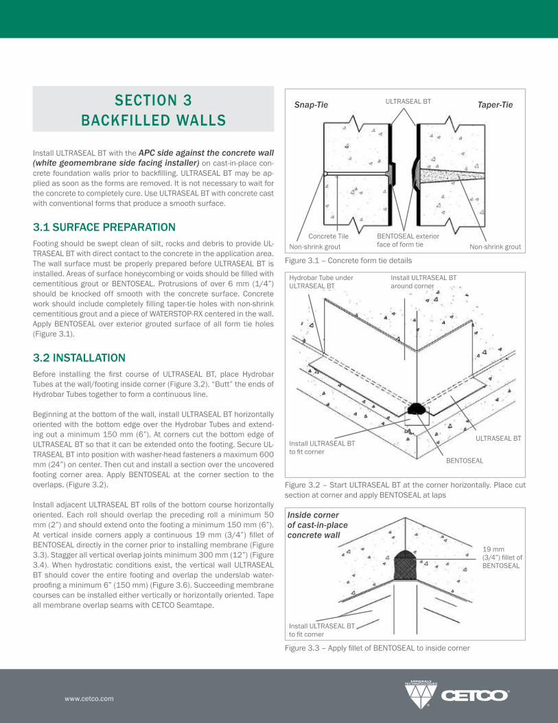
BACKFILLED WALLS
Install ULTRASEAL BT with the APC side against the concrete wall (white geomembrane side facing installer) on cast-in-place con-
cretefoundationwallspriortobackilling.ULTRASEALBTmaybeap-
plied as soon as the forms are removed. It is not necessary to wait for
the concrete to completely cure. Use ULTRASEAL BT with concrete cast
with conventional forms that produce a smooth surface.
3.1 SURFACE PREPARATION
Footing should be swept clean of silt, rocks and debris to provide UL-
TRASEAL BT with direct contact to the concrete in the application area.
The wall surface must be properly prepared before ULTRASEAL BT is
installed.AreasofsurfacehoneycombingorvoidsshouldbeilledwithcementitiousgroutorBENTOSEAL.Protrusionsofover6mm (1/4”)should be knocked off smooth with the concrete surface. Concrete
workshould includecompletelyillingtaper-tieholeswithnon-shrinkcementitiousgroutandapieceofWATERSTOP-RXcenteredinthewall.ApplyBENTOSEALoverexteriorgroutedsurfaceofall form tieholes(Figure 3.1).
3.2 INSTALLATION
Before installing the irst course of ULTRASEAL BT, place HydrobarTubes at the wall/footing inside corner (Figure 3.2). “Butt” the ends of
Hydrobar Tubes together to form a continuous line.
Beginningatthebottomofthewall,installULTRASEALBThorizontallyoriented with the bottom edge over the Hydrobar Tubes and extend-
ing out a minimum 150 mm (6”). At corners cut the bottom edge of
ULTRASEAL BT so that it can be extended onto the footing. Secure UL-
TRASEAL BT into position with washer-head fasteners a maximum 600
mm (24”) on center. Then cut and install a section over the uncovered
footing corner area. Apply BENTOSEAL at the corner section to theoverlaps. (Figure 3.2).
InstalladjacentULTRASEALBTrollsofthebottomcoursehorizontallyoriented. Each roll should overlap the preceding roll a minimum 50
mm (2”) and should extend onto the footing a minimum 150 mm (6”).
At vertical inside corners apply a continuous 19 mm (3/4”) illet ofBENTOSEALdirectlyinthecornerpriortoinstallingmembrane(Figure3.3). Stagger all vertical overlap joints minimum 300 mm (12”) (Figure
3.4).Whenhydrostaticconditionsexist, theverticalwallULTRASEALBT should cover the entire footing and overlap the underslab water-
prooingaminimum6”(150mm)(Figure3.6).Succeedingmembranecoursescanbeinstalledeitherverticallyorhorizontallyoriented.Tapeall membrane overlap seams with CETCO Seamtape.
Figure3.2–StartULTRASEALBTatthecornerhorizontally.PlacecutsectionatcornerandapplyBENTOSEALatlaps
Figure 3.1 – Concrete form tie details
Figure3.3–ApplyilletofBENTOSEALtoinsidecorner
Snap-Tie Taper-Tie
Non-shrinkgroutConcrete Tile BENTOSEALexterior
face of form tie Non-shrinkgrout
ULTRASEAL BT
Install ULTRASEAL BT around corner
Hydrobar Tube under ULTRASEAL BT
ULTRASEAL BT
BENTOSEAL
Install ULTRASEAL BT toitcorner
Install ULTRASEAL BT toitcorner
19 mm (3/4”)illetofBENTOSEAL
Inside corner of cast-in-place concrete wall

PRODUCT MANUAL
- 20 -North America: +1 847.851.1800 | +1 800.527.9948 | www.cetco.com
ULTRASEAL®
ADVANCED APC WATERPROOFING SYSTEM
Figure3.4–ULTRASEALBTinstalledoncast-in-placebackilledwall,overlapedges50mm(2”)andinstallSeamtape
Backill: The excavated area should be backilled and compactedpromptly after ULTRASEAL BT is installed. Use placed backill as aplatforminapplyingsucceedingULTRASEALBTcourses.Thebackillmustbecompacted toaminimumof85%ModiiedProctordensity.Backillshouldconsistofcompactiblesoilsorangularaggregate(19mm(3/4")orless)freeofdebris,sharpobjectsandstonelargerthan19mm (3/4”). When backill cannot be placed immediately, protectmembrane from precipitation and debris by sealing edges to concrete
substrate with CETCO Seamtape or tooled bead of CETSEAL. This tem-
porary termination can be left in place covered by subsequent mem-
brane overlap. Figure 3.5 – Minimum ULTRASEAL BT overlap detail
Figure 3.6 – Step by step detail of outside wall base corner installation (hydrostatic condition)
TrowelBENTOSEALovergrouted form-tie holes
ULTRASEAL BT
Hydrobar Tubes placed under ULTRASEAL BT at transition at footing
Install ULTRASEAL BT with APC side against the concrete (white geomembrane side facing installer
Stagger end seams a minimum 300 mm (12”)
Mechanically fasten ULTRASEAL BT maximum 600 mm (24”) on center
Install CETCO Seamtape at membrane overlaps
50 mm (2”) overlap
WATERSTOP-RX(min 75 mm (3”) coverage)
150 mm (6”)
Min. 50 mm (2”)
Cast-in-place concrete wall
Washer-headmechanicalfastener
ULTRASEAL BT
CETCO Seamtape
Step 1. Step 2.
Step 3. Step 4.
ULTRASEAL BT turned up from underslab
Trowel BENTOSEALatcorner
CutandfoldirstULTRASEAL BT section
Cut and fold second ULTRASEAL BT section
Place third ULTRASEAL BT piece over the previous two sections
TermbarandBENTOSEAL

www.cetco.com
3.3 BACKFILLED WALL PENETRATIONS
CutULTRASEALBT tocloselyitaroundpenetrations.After installingmembrane,trowelaminimum19mm(3/4”)thickilletofBENTOSEALaroundthepenetrationandthemembrane.ExtendBENTOSEALontothepenetration38mm(1–1/2”)andcovermembraneedge(Figure3.7). In areas where multiple penetrations are close together, it may
be impractical tocutULTRASEALBT toitaroundbaseofeachpen-
etration.Therefore,applya19mm (3/4”) thickilletofBENTOSEALaround each penetration and cover the entire surface between the
penetrations(Figure3.8).ExtendBENTOSEAL38mm(1–1/2”)ontothe penetrations.
Figure 3.7 – Single penetration cast-in-place wall detail
Figure 3.10 – Install ULTRASEAL BT between penetrations with acces-
sibility.TrowelBENTOSEALaroundpenetrationsFigure3.8–CutULTRASEALBTtoitaroundpenetrations
Figure3.9–Closemultiplepenetrations.TrowelBENTOSEALaroundand between penetrations
ULTRASEAL BT
Cast-in-place concrete wall
BENTOSEALtroweled around penetration
Pipe
WATERSTOP-RX(min. 75 mm (3”) coverage)
ULTRASEAL BT ApplyBENTOSEALtocutoutarea
ULTRASEAL BT cut out around multiple penetrations
WATERSTOP-RX
ULTRASEAL BT
BENTOSEAL
Pipe
BENTOSEAL
Pipe
ULTRASEAL BT
WATERSTOP-RX
WATERSTOP-RX
ULTRASEAL BT
BENTOSEAL
Pipe
BENTOSEAL
ULTRASEAL BT
BENTOSEAL
Pipe
ULTRASEAL BT
WATERSTOP-RX
PRODUCT MANUAL
- 22 -North America: +1 847.851.1800 | +1 800.527.9948 | www.cetco.com
ULTRASEAL®
ADVANCED APC WATERPROOFING SYSTEM
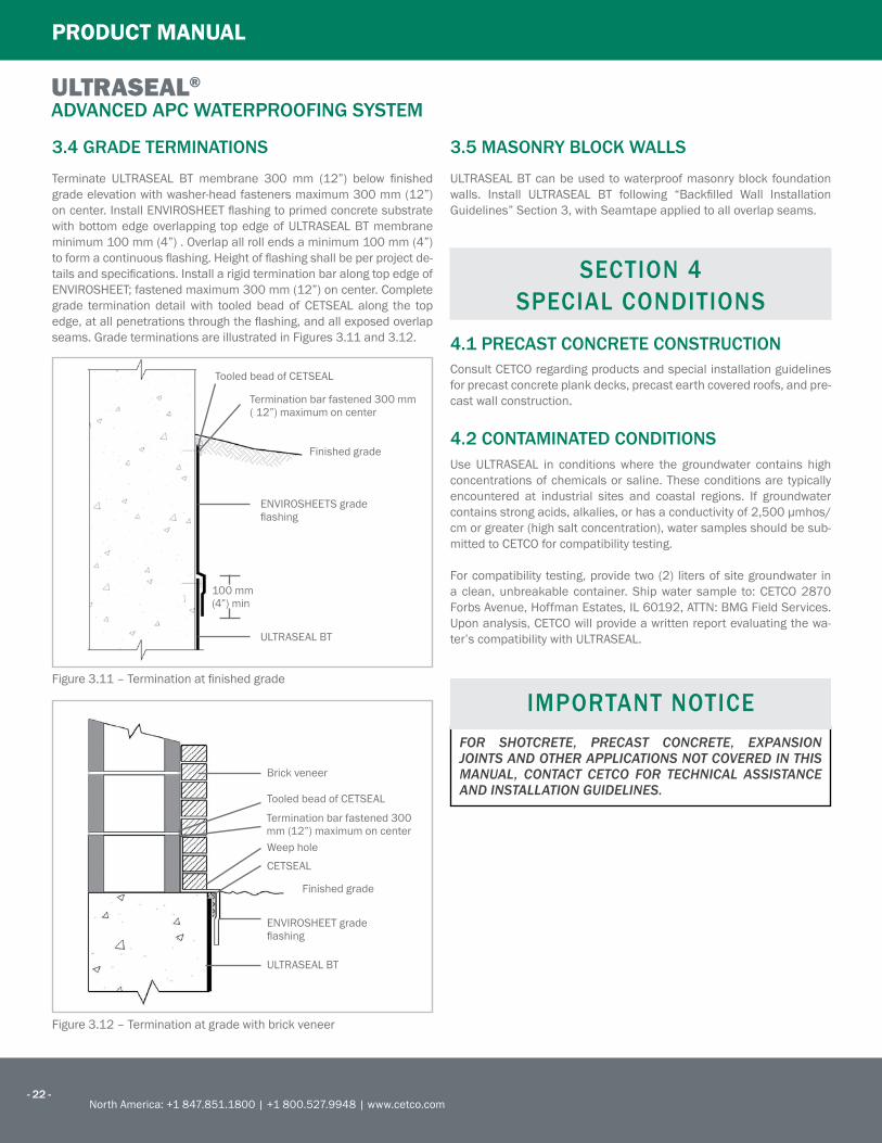
3.4 GRADE TERMINATIONS
Terminate ULTRASEAL BT membrane 300 mm (12”) below inishedgrade elevation with washer-head fasteners maximum 300 mm (12”)
oncenter.InstallENVIROSHEETlashingtoprimedconcretesubstratewith bottom edge overlapping top edge of ULTRASEAL BT membrane
minimum 100 mm (4”) . Overlap all roll ends a minimum 100 mm (4”)
toformacontinuouslashing.Heightoflashingshallbeperprojectde-
tailsandspeciications.InstallarigidterminationbaralongtopedgeofENVIROSHEET;fastenedmaximum300mm(12”)oncenter.Completegrade termination detail with tooled bead of CETSEAL along the top
edge,atallpenetrationsthroughthelashing,andallexposedoverlapseams. Grade terminations are illustrated in Figures 3.11 and 3.12.
3.5 MASONRY BLOCK WALLS
ULTRASEAL BT can be used to waterproof masonry block foundation
walls. Install ULTRASEAL BT following “Backilled Wall InstallationGuidelines” Section 3, with Seamtape applied to all overlap seams.
SECTION 4
SPECIAL CONDITIONS
4.1 PRECAST CONCRETE CONSTRUCTION
Consult CETCO regarding products and special installation guidelines
for precast concrete plank decks, precast earth covered roofs, and pre-
cast wall construction.
4.2 CONTAMINATED CONDITIONS
Use ULTRASEAL in conditions where the groundwater contains high
concentrations of chemicals or saline. These conditions are typically
encountered at industrial sites and coastal regions. If groundwater
containsstrongacids,alkalies,orhasaconductivityof2,500μmhos/cm or greater (high salt concentration), water samples should be sub-
mitted to CETCO for compatibility testing.
For compatibility testing, provide two (2) liters of site groundwater in
aclean,unbreakablecontainer.Shipwater sample to:CETCO2870ForbsAvenue,HoffmanEstates,IL60192,ATTN:BMGFieldServices.Upon analysis, CETCO will provide a written report evaluating the wa-
ter’s compatibility with ULTRASEAL.
Figure3.11–Terminationatinishedgrade
Figure 3.12 – Termination at grade with brick veneer
IMPORTANT NOTICE
FOR SHOTCRETE, PRECAST CONCRETE, EXPANSION JOINTS AND OTHER APPLICATIONS NOT COVERED IN THIS MANUAL, CONTACT CETCO FOR TECHNICAL ASSISTANCE AND INSTALLATION GUIDELINES.
Brick veneer
Weephole
CETSEAL
Finished grade
ENVIROSHEETgradelashing
ULTRASEAL BT
ENVIROSHEETSgradelashing
ULTRASEAL BT
100 mm (4”) min
Finished grade
Tooled bead of CETSEAL
Termination bar fastened 300 mm ( 12”) maximum on center
Tooled bead of CETSEAL
Termination bar fastened 300 mm (12”) maximum on center
www.cetco.com
The information and data contained herein is believed to be accurate and
reliable.Speciicationsandotherinformationcontainedhereinsupersedeallpreviously printed material and are subject to change without notice.
Manufacturer’s warranty of installed system is available. Contact seller for
terms and sample documents including all limitations.
All goods sold by seller are warranted to be free from defects in material and
workmanship.
The foregoing warranty is in lieu of and excludes all other warranties not ex-
pressly set forth herein, whether expressed or implied by operation of law or
otherwise including but not limited to any implied warranties of merchant-
abilityoritness.Seller shall not be liable for incidental or consequential losses, damages or
expenses, directly or indirectly arising from the sale, handling or use of the
goods, or from any other cause relating thereto, and seller’s liability hereun-
der in any case is expressly limited to the replacement (in the form originally
shipped) of goods not complying with this agreement or at seller’s election, to
the repayment of, or crediting buyer with, an amount equal to the purchase
price of such goods, whether such claims are for breach of warranty or neg-
ligence.
Any claim by buyer with reference to the goods sold hereunder for any cause
shall be deemed waived by buyer unless submitted to seller in writing within
thirty (30) days from the date buyer discovered or should of discovered, any
claimed breach.
Materials should be inspected and tested by purchaser prior to their use if
productqualityissubjecttoveriicationaftershipment.Performanceguaran-
tees are normally supplied by the applicator.
Note:ULTRASEALwaterprooingsystemisnotanexpansionjointmaterial.
LIMITED WARRANTY
IMPORTANT NOTICE
Contact CETCO for veriication of speciication and instal-lation requirements to comply for eligibility of HydroShield Warranty.

www.cetco.com
FORM:PM_ULTRASEAL_AM_EN_201509_V3
www.cetco.com | [email protected]
UPDATED:SEPTEMBER2015©2015CETCO.IMPORTANT:Theinformationcontainedhereinsupersedesallpreviousprintedversions,andisbelieved to be accurate and reliable. For the most up-to-date information, please visit www.CETCO.com. CETCO accepts no responsibility for the results obtained through application of this product. CETCO reserves the right to update information without notice.